
PSW503ST - PA speaker Pyle - Free user manual and instructions
Find the device manual for free PSW503ST Pyle in PDF.

| Product Type | TV Wall Mount Bracket |
| Brand | Pyle |
| Model | PSW503ST |
| Weight Capacity | 10 kg - 50 kg (22 lbs - 110 lbs) |
| TV Size Compatibility | 26" - 42" |
| Adjustable Tilt Angle | 5° to 15° |
| Mount Type | Wall mount, double deck |
| Safety Feature | Locking bolt at bottom |
| Leveling System | Built-in bubble level |
| Cable Management | Cable cover included |
| Included Hardware | Wall mount, left/right brackets, cable cover, safe bolts, box wrench, various screws, spacers, washers, wall anchors |
| Compatible Wall Types | Wooden, brick, concrete, stone (not steel stud or cinder block) |
| Material | Steel |
| Color | Black |
| Installation | DIY, easy hang-up design |
| Weight | Approx. 3 kg |
| VESA Compatibility | Up to 200x200 mm |
| Country of Origin | China |
Frequently Asked Questions - PSW503ST Pyle
User questions about PSW503ST Pyle
0 question about this device. Answer the ones you know or ask your own.
Ask a new question about this device
Download the instructions for your PA speaker in PDF format for free! Find your manual PSW503ST - Pyle and take your electronic device back in hand. On this page are published all the documents necessary for the use of your device. PSW503ST by Pyle.
USER MANUAL PSW503ST Pyle
Step 4: Hanging display
Firstly lift the bracket mounted display over the wall mount. And then hook the brackets over the top of the wall mount. Rotate the display let the bottom of the brackets hook over the bottom of wall mount, as shown in Fig.4a. Then put safe bolts into the bottom of the brackets and lock it, as shown in Fig.4b.
Warning: Some TV require two people to lift, as we are not responsible for any personal injury or product damage due to mishandling.
natural_image
Technical line drawing of a mechanical assembly with labeled parts (no text or symbols)Fig 4a
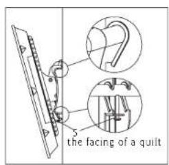
Fig 4b
Thank you for choosing our products
Pyle Audio
1600 63rd st, Brooklyn, NY, 11204
(718)236-8000

Tilt Flat Panel TV Bracket
Multifunctional double deck wall mount
INSTALLATION GUIDE
Item No.:PSW503STItem No.:PSWS
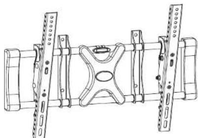
natural_image
Technical line drawing of a mechanical assembly with mounting brackets and structural supports (no text or symbols)- Easy installing: Just hang up the display
• Safety: locking by spinning bolt on the bottom
• Weight Capacity: 10kg/22lbs--50kg/110lbs
• TV size range: 26"\~42" - Adjustable angle: 515\~
- Inside has balance adjust system www.pyleaudio.com.
- Bulit in leveler system MADE IN CHINA
IMPORTANT: If don't understand about right install ways, please consult to normal installing specialist.
Hardware List: Actual parts appearance and the quantity may different with illustrated.

| ID | Description | |
| 1 | 1 | Wall mount |
| 2 | 1 | Left bracket |
| 3 | 1 | Right bracket |
| 4 | 1 | Cable Cover |
| 5 | 2 | Safe bolt |
| 6 | 1 | Box wrench |
| A | 4 | M4 mm×12 bolt |
| B | 4 | M4 mm×16 bolt |
| C | 4 | MS×mm16 bolt |
| ID | Qty | Description |
| D | 4 | M6×16mm bolt |
| E | 4 | M5×36mm bolt |
| F | 4 | M6×36mm bolt |
| G | 4 | Square washer |
| H | 4 | Long bolt |
| I | 4 | Wall anchor |
| J | 4 | Long bolt washer |
| K | 4 | Spacer |
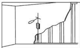
After determining the height of stand, follow the installation instructions in below to install wall mount to different kinds of wallwooden, brick, concrete and stone.
Wooden wall:
Using a awl or nail to make where the nails are located, as shown as Fig.3b. Distance between two nails for fixing wall mount must not less than 16. Slide the plate into position as required.(Fig.3c) Pre-drill these holes with a 5mm drill bit to at least 40mm in deep hole. Use wall mount as a template to mark the location of other three holes and drill the same holes please make sure these holes are level and eudipleural. Fixthewallmounttothewallwith4longbolts(H)andbyboxhwaren(J)(6).
Brick, Concrete and Stone wall:
Using a awl or nail to make where the nails are located. Distance between two nails for fixing wall mount must not less than 16. Slide the plate into position as required. (Fig.3c) Pre-drill these holes with a 10mm drill bit to at least 50mm in deep hole. Use wall mount as a template to mark the location of other three holes and drill the same holes. Please make sure these holes are level and eudipleural. Insert wall anchors(I) into each of these holes. Attach the wall mount to the wall using 4 long bolts(H) and washers(J) by box wrench(6).
natural_image
Simple line drawing of a room with vertical bars and a central object (no text or symbols)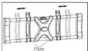
Fig 3b Fig 3c

Using balance-adjusting system on the plate, make sure whether wall plate is installed balance. If not, then slide the wall plate let pointer level in the center position.
Fig 3d
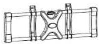
Step 2: Install the Cable Cover
Route the cables as required. Snap the cable cover into place onto the rods (Fig. 2a), and then slide the cover into position as required. (Fig. 2b)
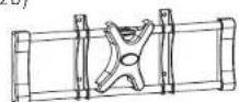
Fig 2a Fig 2a
Step 3: Attach to wall to wall
First, determine the height of stand
The best height of stand is parallel to eyelevel of a person who sitting on a couch. Normally, the horizontal distance of eyelevel is about 4' from ground level.
The following two conditions are for determining the perfect height of stand:
1) the distance between wall and couch(Fig 3a).
2) the distance of eyelevel from ground level plus the distance measured from eyelevel of a person sitting on couch with viewing angle of 15 (Fig 3a)
For example:
1) the distance of 'a' is 5'-7', the distance of 'b' is about 1'
2) the distance of 'a' is 8'-13', the distance of 'b' is about 3'
3) the distance of 'a' is 14'-17', the distance of 'b' is about 4'
The perfect height of stand centre will be anywhere within b, where you feel comfortable for viewing.

Fig 3a

We are not responsible for any personal injury or product damage due to mishandling, incorrect mounting, incorrect assembly or incorrect use of this product.
Note: The supplied wall mounting hardware is not for use on steel stud walls or cold cinder block walls. If you are uncertain about the nature of your wall, please consult a qualified contractor. If the hardware you required is not included please contact your local hardware store.
Caution: This Product LCD /Plasma Wall Mount Bracket is intended for use only with the maximum weights indicated. See apparatus instructions. Use with products heavier than the maximum weights indicated may result in instability causing possible injury.
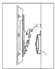
Step 1: Attach bracket to TV
Check your TV manual to confirm the diameter of bolt to be used or choose an appropriate bolt according to size, height and position of the holes on your TV. See pages 4-5 of these instructions for examples.
For correct installing, make sure that hook of every bracket must facing down. Use selected bolts, spacers and washers for installing bracket at the back of display. Adjust two brackets to equal heights and level. Once aligned, tightly secure the bolts.
IMPORTANT: Don't force the bolt into the hole, which will cause a damage of equipments and injure of person. Don't use electric drill to fasten any bolts.
Following examples shows how to use bolts, spacers and square washers.
- Some displays have vertical backs. No spacer is required. Install the bracket directly to the back of display by using bolts and square washers provided. As shown in Fig.1a.

Fig 1a
- Some displays have curved backs with recessed mounting lands(Fig.a). It will require the use of spacer. For this display, install a spacer(K) between display and the bracket. AsshowninFig1b.
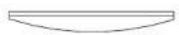
Fig a

Fig 1b
Brand : Pyle
Model : PSW503ST
Category : PA speaker