USER MANUAL Unidoor-X E3261434L-04 DreamLine
DreamLine® reserves the right to alter, modify or redesign products at any time without prior notice. For the latest up-to-date technical drawings, manuals, warranty information or additional details please refer to your model's web page on DreamLine.com
natural_image
Isometric line drawing of a two-door industrial enclosure or cabinet (no text or symbols)
natural_image
Isometric line drawing of a two-door industrial cabinet or enclosure with doors and windows (no text or symbols)
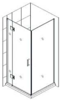
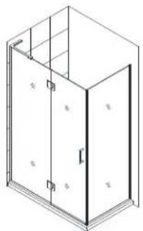
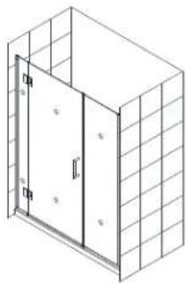
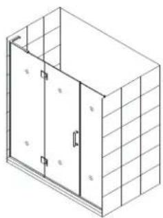
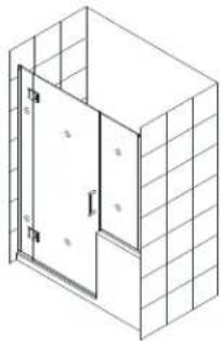
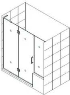
STYLE M3
natural_image
Isometric line drawing of a door frame with no text or symbols
natural_image
Isometric line drawing of a two-story building facade with windows and doorways (no text or symbols)
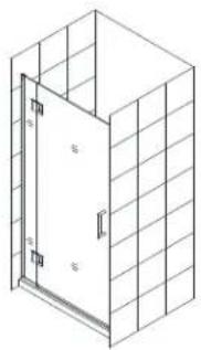
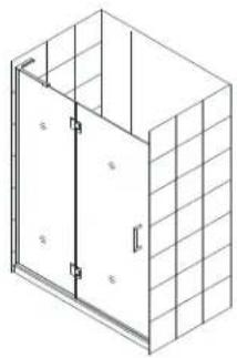
STEP 1: Install Shower Door
natural_image
Isometric line drawing of a 3D room corner with a vertical panel and grid walls (no text or symbols)
STEP 2: Install Panels

Questions?
Please Call DreamLine Customer Support: 1-855-831-2126
Hours of Operation M-F 8AM - 7PM EST and Saturday 9AM - 5PM EST
Support@DreamLine.com

For more information about DreamLine Shower Doors, Tub Doors and Enclosures, please visit DreamLine.com
UNIDOOR-X Style M
DreamLine® reserves the right to alter, modify or redesign products at any time without prior notice. For the latest up-to-date technical drawings, manuals, warranty information or additional details please refer to your model's web page on DreamLine.com
natural_image
Two isometric line drawings of a two-story building facade with internal doorways and window grilles (no text or symbols)
Right Hand Door installation shown

Questions?
Please Call DreamLine Customer Support: 1-855-831-2126
Hours of Operation M-F 8AM - 7PM EST and Saturday 9AM - 5PM EST
Support@DreamLine.com

For more information about DreamLine® products please visit DreamLine.com
text_image
CLEARMAX™
This model is treated with DreamLine's exclusive ClearMax^TM Glass technology. This is a specially-formulated coating that prevents the build up of soap and water spots.
Install the surface with the ClearMax™ label towards the inside of the shower. Please note that depending on the model, the glass may be coated on either one or both surfaces.
For best results, squeegee the glass after each use and dry with a soft cloth.
Model Numbers
natural_image
Isometric line drawing of a single door open in a grid-patterned cabinet (no text or symbols)
UNIDOOR-X Style M
with 6" hinge panel with Hinge Panel Glass Bracket
D12372-##
D12472-##
D12572-##
D12672-##
D12772-##
D12872-##
D12972-##
D13072-##
natural_image
Isometric line drawing of a modular cabinet or enclosure with no text or symbols
UNIDOOR-X Style M
with 24" hinge panel
with Left or Right L-Bracket
D32372L-##
D32372R-##
D32472L-##
D32472R-##
D32572L-##
D32572R-##
D32672L-##
D32672R-##
D32772L-##
D32772R-##
D32872L-##
D32872R-##
D32972L-##
D32972R-##
D33072L-##
D33072R-##
- hardware finish
01- Chrome
04- Brushed Nickel
06- Oil Rubbed Bronze
09 - Satin Black
Unidoor-X Style M manual used with the following Model Styles:
natural_image
Isometric line drawing of a two-door shower enclosure with no text or symbols
Style L1
natural_image
Isometric line drawing of a two-story cabinet or enclosure with mounting holes and ventilation grilles (no text or symbols)
natural_image
Isometric line drawing of a door opening inside a wall-mounted cabinet (no text or symbols)
natural_image
Isometric line drawing of a two-story building with windows and doors (no text or symbols)
Style M
natural_image
Isometric line drawing of a two-story window with a door and side panel (no text or symbols)
Style M1
natural_image
Isometric line drawing of a cabinet or enclosure with windows and doors, no text or symbols present
natural_image
Isometric line drawing of a two-story window with a door and grid-patterned walls (no text or symbols)
natural_image
Isometric line drawing of a two-story building facade with windows and doorways (no text or symbols)
Style M2
natural_image
Isometric line drawing of a two-door industrial cabinet or enclosure (no text or symbols)
Style M3
natural_image
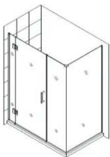
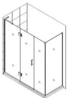
Isometric line drawing of a two-story cabinet or enclosure with windows and doors (no text or symbols)
natural_image
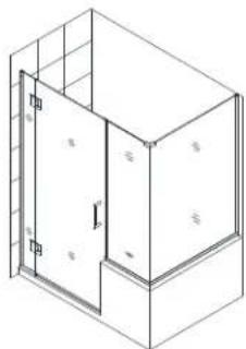
Isometric line drawing of a two-story building with a door and windows (no text or symbols)
natural_image
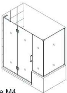
Isometric line drawing of a two-story building facade with windows and doorways (no text or symbols)
Style M4

When installing one of the configurations shown above with glass-to-glass hinges, discard the Style A manual that is packaged with the door glass and use this Style M manual for the installation of the hinge panel glass and door glass.
Next, use the manual that is packaged with the panel glass for the panel installation instructions based on the Style or configuration:
■ for Style M1 - use manuals for Style M & Style F
■ for Style M2 - use manuals for Style M & Style G
■ for Style M3 - use manuals for Style M & Style I
■ for Style M4 - use manuals for Style M & Style J
■ for Style L1 - use manuals for Style M & Style L
STYLE L1 \*
UNIDOOR-X Shower door 23"\~30" with 6" or 24" hinge panel and with 30"-34" full height return panel secured using u-channel
STYLE M \*
UNIDOOR-X Shower door 23"\~30" with 6" or 24" hinge panel secured using u-channel
STYLE M1 \*
UNIDOOR-X Shower door 23"\~30" with 6" or 24" hinge panel and with 6", 6-1/2", 14", 14-1/2", 22" or 22-1/2" full height inline panel secured using u-channel
STYLE M2 \*
UNIDOOR-X Shower door 23"\~30" with 6" or 24" hinge panel with 12", 18", 24" or 26" inline buttress panel secured using u-channel
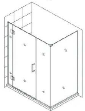
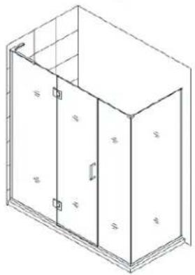
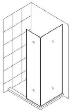
STYLE M3 \*
UNIDOOR-X Shower door 23"\~30" with 6" or 24" hinge panel, with 6", 6-1/2", 14", 14-1/2", 22" or 22-1/2" full height inline panel and 30" - 34" full height return panel secured using u-channel
STYLE M4 \*
UNIDOOR-X Shower door 23"\~30" with 6" or 24" hinge panel, with 12", 18", 24" or 26" in-line buttress panel and 30", 36" or 40" buttress return panel secured using u-channel
* For the panel installation instructions, please refer to the separate manual included in the panel glass packaging.
Depending on the panel glass size, some panel glass may have both an inline panel manual and a return panel manual. Use the appropriate manual for the model style/configuration.
For Example: a 30" full height panel can be used as an inline panel or a full height return panel.
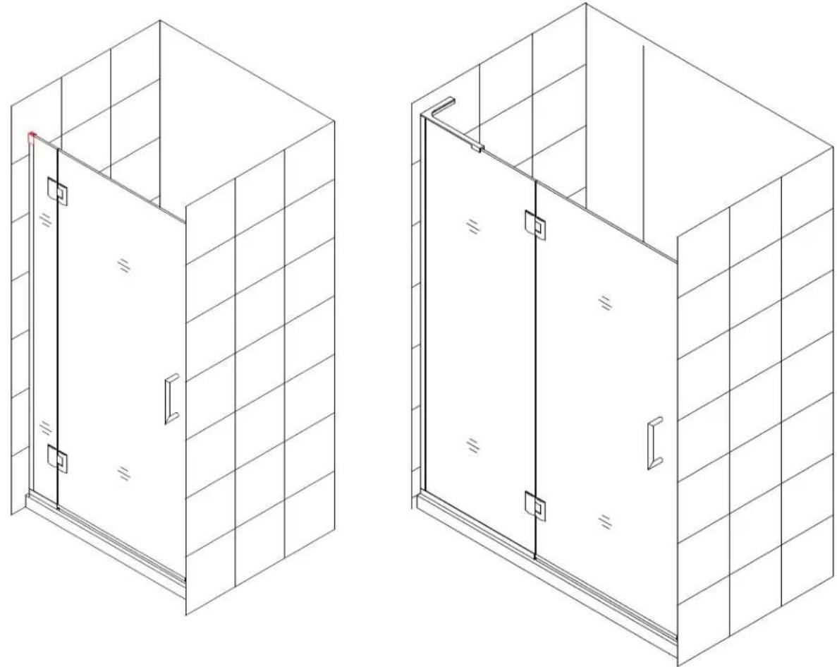
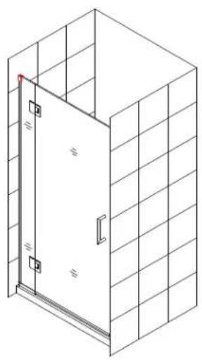
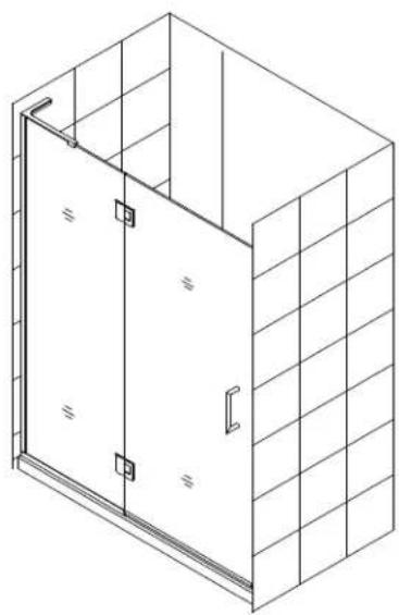
NOTE: The Unidoor series doors and enclosures are reversible for left or right-hand door installation. This manual will show the right-hand door installation. For a left-hand door installation, simply begin on the opposite wall and reverse the orientation of the parts as necessary.
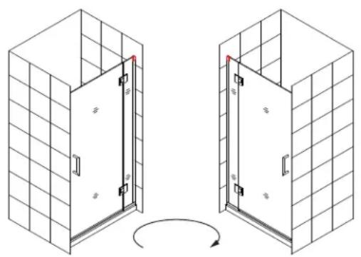
natural_image
Diagram showing two 3D door arrangements with grid walls and a curved arrow indicating rotation (no text or symbols)
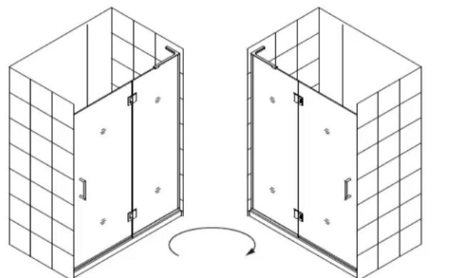
natural_image
Isometric line drawing of two identical 3D door compartments with grid walls, no text or symbols present
use Right-hand L-bracket
use Left-hand L-bracket
Preparation
- Prior to installation, examine all boxes and packages for shipping damage and compare the piece count with your packing slip. After opening all boxes and packages read this introduction carefully. Check that all of the needed parts are included in the package by checking off the components on the "Detailed Diagram of Shower Door Components". If the unit has been damaged, has a finishing defect, or has missing parts, please contact our customer support department within 3 business days of the delivery date. Please note that DreamLine® will not replace any damaged products or missing parts free of charge after 3 business days or if the product has been installed. Feel free to contact DreamLine® if you have any questions, and please provide an order number, job name or other proof of purchase to help us identify your original order.
- Please note that you should consult your local building codes with questions on installation compliance standards. Building and plumbing codes may vary by location, and DreamLine® is not responsible for code compliance standards for your project and will not accept any returns.
- If this unit is going to be installed in a new construction, please install all of the required plumbing and drainage before installing the shower. Use a competent and licensed (if required by local code) plumber for all plumbing installation.
- Please make sure that prior to beginning the installation, the surfaces are leveled and solid and will be able to support the total weight of the unit. Also make sure the walls are at right angles. Irregular installation surface level, radius corners or improper angle of side walls will result in serious problems for your installation. Note that some adjustments and drilling will be necessary during the installation process.
- Please protect all primary surfaces of the product during installation. Never set the glass down directly onto a tile floor. Leave corner protectors in place until it is necessary to remove them. Always use a piece of wood or cardboard to protect the bottom edge and corners of the glass prior to and during installation.
- This unit must be installed upon a finished threshold and against finished walls.
- The hinge panel glass for this model should not be adjusted more than 1/4" for out-of-plumb within the U-channel. This model does NOT have any adjustment for overall width. Verify that the model size ordered will fit the finished opening before beginning installation.
- This model requires that you drill into the threshold for proper installation.
- It is recommended to install the hinge-side U-channel into a stud.
- This model requires minimum 5/8" of flat threshold space for installation.
Professional installation recommended

NOTE: DO NOT install the handle onto the door glass until instructed to do so. DO NOT attempt to lift the glass using the handle. This could result in damage to the glass and/or serious personal injury. Always use an assistant or a professional grade glass suction cup when handling heavy glass.
Tape Phillips
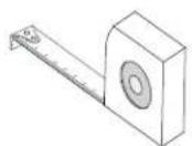
Measure
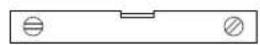
PencilLevel
Screwdriver
Hammer
Drill bit
(∅=5/16")

Drill bit Power ( =1/8" )
Drill
natural_image
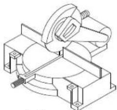
Technical line drawing of a mechanical clamp or bracket assembly (no text or symbols)
Miter saw
or Hacksaw
Metal File
Silicone*
*Quick-drying/fast curing silicone recommended for the installation of hinge panels.
Table of Contents
| Section title | Page # |
| Preparation | 6 |
| Tools | 7 |
| Parts List | 8 |
| Hinge Panel Glass Bracket installation | 10~14 |
| Hinge Panel Glass with L-Bracket installation | 15~21 |
| Hinges and Door Glass installation | 22~23 |
| Vinyl Seals | 24~25 |
| Adjustable Hinge instructions | 27 |
| Product maintenance | 28 |
NOTE: Unpack your unit carefully and inspect it. Lay it out and identify all parts using the detailed diagram and packing list in your manual as a reference. Before discarding the carton, check for small hardware bags that may have fallen to the bottom of the box. If any parts are damaged or missing, please contact DreamLine® for replacement. The shipping boxes may contain extra parts not used in your model configuration.
Retain these installation instructions for future reference.
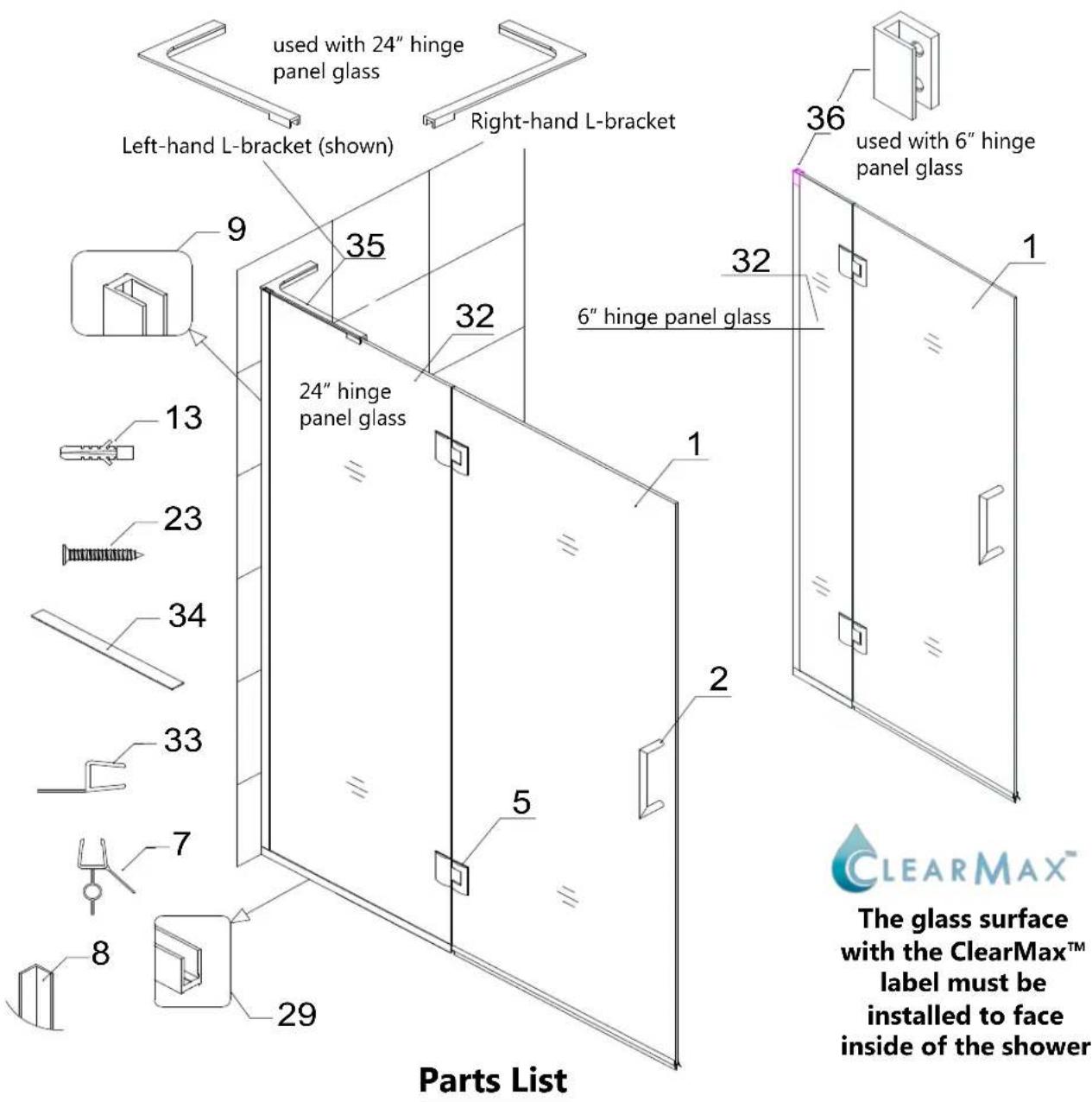
Detailed Diagram of shower door components
text_image
used with 24" hinge
panel glass
Left-hand L-bracket (shown)
Right-hand L-bracket
35
9
32
36
used with 6" hinge
panel glass
24" hinge
panel glass
6" hinge panel glass
13
23
34
33
7
8
29
1
2
5
1
Parts List
ClearMax™
The glass surface
with the ClearMax™
label must be
installed to face
inside of the shower
| 01 | Door Glass | 1pc | 23 | Countersunk screw ST4.2x40 | 8pcs |
| 02 | Handle | 1pc | 29 | U-channel 2 (44", bottom profile) | 1pc |
| 05 | Glass-to-Glass Hinge | 2pcs | 32 | Hinge panel glass (6" or 24")*** | 1pc |
| 07 | Bottom anti-water strip | 1pc | 33 | Flanged anti-water strip | 1pc |
| 08 | L-shaped strip * | 1pc | 34 | PVC glass spacer (0.5mm) | 1pc |
| 09 | U-channel 1 (76", wall profile) | 1pc | 35 | L-Bracket (Left or Right) (for 24")** | 1pc |
| 13 | ∅5/16" Wall anchor | 5pcs | 36 | Hinge Panel Glass Bracket (for 6") ^ | 1pc |
* L-shaped strip (#08) only used for Style M configuration
** L-Bracket (for 24" hinge panel glass) is not included with 6" hinge panel glass
*** Hinge panel glass - the top hinge cutout is 7-7/8" to center, the bottom cutout is 8-3/8" to center.
^ Hinge Panel Glass Bracket (#36) is for the 6" hinge panel only and is not to be used with the 24" hinge panel glass
Installation steps
Style M - 6" & 24" Inline Panel and Shower Door Installation
NOTE: The following shower door installation instructions should be used as a general guide and prerequisite to the installation of the UNIDOOR Style M, M1, M2, M3, M4 and L1 models. Before you begin the installation, please check your finished opening size and model dimensions to ensure proper placement of the Hinge Panel Glass (#32) and Door Glass (#01). Specific size information can be found on our website: DreamLine.com.
NOTE: The 24" Hinge Panel Glass (#32) installs with either a left or right L-Bracket (#35). (Fig 1)
The 6" Hinge Panel Glass installs with the Hinge Panel Glass Bracket (#36). (Fig 2)
This manual includes the instructions for both methods.

NOTE: There is a top and a bottom to the Hinge Panel Glass (#32): The top hinge cutout is 7-7/8" to center, the bottom hinge cutout is 8-3/8" to center. The hinge panel glass must be installed correctly.
NOTE: For the 6" Hinge Panel Glass (#32) installation, begin with Step #1. The Hinge Panel Glass Bracket (#36) installs at the top of the vertical U-channel. (Fig 2)
The Hinge Panel Glass Bracket (#36) is only for use with the 6" Hinge Panel Glass (#32). DO NOT USE this bracket with the 24" hinge panel glass.
For the 24" Hinge Panel Glass (#32) installation with the L-Bracket (#35), begin with Step #10 on Page 15.
Note: The L-Bracket (#35) is not included with the 6" hinge panel installation.
NOTE: It is strongly recommended that the silicone be allowed to fully cure in the U-channels before hanging the door glass.
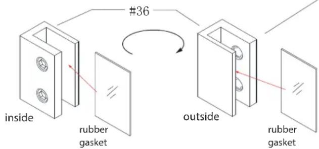
text_image
inside
rubber
gasket
#36
outside
rubber
gasket
NOTE: The Hinge Panel Glass Bracket (#36) is only to be installed with the 6" Hinge Panel Glass (#32) for the UNIDOOR-X models. Maximum out-of-plumb adjustment for Hinge Panel Glass = 1/4"
text_image
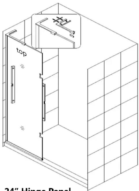
top
24" Hinge Panel
24" Hinge Panel with left L-bracket (#35)
Fig 1

natural_image
Pure architectural line drawing of a vertical structure with a circular detail and diagonal lines, no text or symbols present.
6" Hinge Panel with
Hinge Panel Glass Bracket (#36)
Fig 2
Installation steps for 6" hinge panel with Hinge Panel Glass Bracket
-
Draw a line on the threshold and on the wall to represent the centerline of the U-channel. Make sure the line is parallel to the front edge of the threshold. (Fig 3)
-
Cut the vertical U-channel to 69-7/16". Cut the bottom U-channel** to 6". (Fig 4)
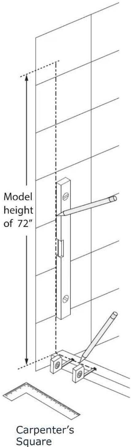
text_image
Model height of 72"
Carpenter's Square
Fig 3
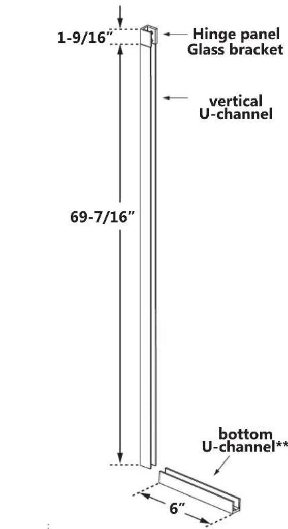
text_image
1-9/16"
Hinge panel
Glass bracket
vertical
U-channel
69-7/16"
bottom
U-channel**
6"
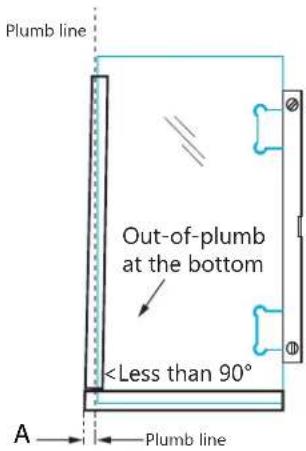
text_image
Plumb line
Out-of-plumb
at the bottom
\*\*If the wall is out-of-plumb at the bottom, measure that dimension (A) and add it to the length of the U-channel (1/4" max): Finished cut length= Glass Width + 3/16" + dimension A
Fig 4
3. Position the U-channels and Hinge Panel Glass Bracket (#36) on the centerlines to mark the holes for drilling. (Fig 5)

natural_image
Technical line drawing of a vertical structural frame with directional arrows indicating movement or force (no text or symbols)
4. Mark the hole positions on the centerline on the wall and threshold through the holes in the U-channels and the Hinge Panel Glass Bracket (#36).
(Note that the Hinge Panel Glass Bracket (#36) is wider than the u-channel). (Fig 6)

natural_image
Technical line drawing of a mechanical assembly with lever and rod components (no text or symbols)
Fig 6Fig 5
5. Drill ∅5/16" holes in the wall and install the wall anchors.
Drill ∅1/8" holes into an acrylic threshold (or ∅5/16" holes and anchors for a tile threshold). (Fig 7)
6. Apply silicone to the back of the U-channels and the screw holes, then install the U-channels and Hinge Panel Glass Bracket (#36) using the ST4.2 x 40mm screws (#23). (Fig 8)

text_image
Ø5/16"
Ø1/8"
(or Ø5/16" & anchor for tile)
Fig 7

text_image
Fig 8
Fig 8
7. Add the 0.5mm shims into the bottom U-channel to protect the bottom corners of the glass.
Apply a bead of silicone into the length of the U-channels. (Fig 9)
Quick-drying/fast curing silicone is recommended for the installation of hinge panel glass into u-channels.

natural_image
Technical line drawing of a mechanical assembly with a cylindrical tool and a support bracket (no text or symbols)
Cut and install two 2"pcs of the 0.5 mm shims (#34) into the bottom U-channel to protect the corners of the glass
Fig 9
8. Install the Hinge Panel Glass (#32) into the U-channel, checking for level and plumb. Install the gasket into the Hinge Panel Glass
Bracket. (Note: Make sure the top of the hinge panel glass is at the top). (Fig 10)
Hinge Panel
Glass Bracket
with gasket

text_image
et
top
7-7/8"
bottom
8-3/8"
Fig 10
9. Tighten the rubber-tipped set screws on the Hinge Panel Glass Bracket (#36) to secure the glass. Do Not overtighten! (Fig 11)

text_image
inside
Fig 11

NOTE: Following the installation of the Hinge Panel Glass (#32), it is strongly recommended that the silicone be allowed to fully cure before hanging the door glass. (Fig 12)
Go to Step #18 on Page 21 to continue the installation of the Hinges, Door Glass and other components.

natural_image
Technical line drawing showing two mechanical assembly configurations with dashed circular annotations (no text or symbols)
Fig 12
Installation steps for 24" hinge panel glass with L-Bracket
10. Cut the vertical U-channel 1 (#09) to 71". (Fig 13)

text_image
U-Channel 1
L
Fig 13
11. Cut the bottom U-channel 2 (#29) to 24" (see note\*\* below). (Fig 14)

text_image
Plumb line
Out-of-plumb
at the bottom
\*\*If the wall is out-of-plumb at the bottom, measure that dimension as (A) and add it to the length of the U-channel (+1/4" max):
Finished cut length= 24" + A OR
Glass Width + 3/16" + dimension A = Finished cut length
NOTE The vertical U-channel for the Hinge Panel glass will accommodate up to 1/4" for out-of-plumb. Do not exceed this amount.
TIP: Use a metal file to remove any burrs from the cut end of the U-channels before placing them onto the glass.

Metal File

text_image
U-Channel 2
L
Fig 14
12. Position the U-channel 2 (bottom profile) (#29) onto the threshold, parallel to the outside edge. Mark the position of the U-channel and mark the position of the holes for drilling. You need to use at least 3 holes for the U-channel 2 (bottom profile) (#29): one near each end and one near the center.
\- Drill the holes into the threshold using an 1 / 8'' drill bit. (Or use a 5 / 16'' bit and anchor for tile)
\- Apply a bead of silicone to the bottom of the U-channel 2 (bottom profile) (#29) and attach it to the threshold using the ST4.2 x 40mm screws (#23) (Fig. 15)
NOTE: If installing this hinge panel and door for one of the Unidoor-X enclosure configurations, it is important that the hinge panel is installed at the correct dimension for the enclosure model size. Refer to panel installation manual packaged with the panel glass for details and dimensions.

text_image
1
wall
inside

text_image
2
wall
inside

text_image
3
wall
Ø 1/8"
(or Ø5/16"
& anchor
for tile)
inside

natural_image
Pure technical line drawing of a mechanical assembly with no text or symbols

text_image
5
wall
inside
Fig 15

text_image
Install the bottom U-channel
parallel to the outside edge
of the threshold
13. Next, position the vertical U-channel 1 (#09) (wall profile) on top of the installed bottom U-channel. Use a level to plumb the U-channel 1 (#09) (wall profile) and mark the positions of the holes for drilling. You need to use at least four holes for the U-channel 1 (#09) (wall profile).
- Drill the holes into the wall using a ∅5/16" drill bit.
- Insert the Wall Anchors (#13) into the 5/16" holes.
- Apply silicone to the back of the U-channel 1 (#09) (wall profile) and attach it to the wall using the ST4.2 x 40mm screws (#23). (Fig 16)

natural_image
Isometric line drawing of a 3D room corner with a wall-mounted bracket and diagonal rail (no text or symbols)
14. Add several 2" pieces of the 0.5mm Adjustment Spacers (#34) into the bottom U-channel to protect the bottom and corners of the glass.
Apply a good quality mildew-resistant silicone into both U-channels. (Fig 17)

text_image
1
U-channel 1
inside
U-channel 2

text_image
2
wall
inside

text_image
5 waterproof
silicone

natural_image
Simple line drawing of a hammer with an arrow and screwdriver, no text or symbols present

text_image
6
Wall
inside
Fig 16

text_image
1
inside

text_image
2
waterproof
silicone

natural_image
Line drawing of a mechanical component inserted into a window frame (no text or symbols)
Fig 17
NOTE: There is a top and a bottom to the Hinge Panel Glass (#32):
The top hinge cutout is 7-7/8" to center, the bottom hinge cutout is 8-3/8" to center.
The hinge panel glass must be installed correctly so that the door glass can be installed correctly.
15. Install the Hinge Panel glass (#32) into the U-channel 2 (#29) (bottom profile) and the U-channel 1 (#09) (wall profile). Apply a dab of silicone to the exposed end of the bottom u-channel. (Fig 18 and 19)

text_image
1
wall
inside

natural_image
Pure technical diagram showing a mechanical assembly with no text, numbers, or symbols

natural_image
Pure technical line drawing of a mechanical joint or bracket with motion arrows, no text or symbols present

natural_image
Technical line drawing of a mechanical assembly with a tool and bracket (no text or symbols)
Fig 18

text_image
top
Fig 19
Installation steps for 24" hinge panel glass with L-Bracket
L- Bracket Assembly Parts List\*\*

text_image
35.5
35.6
35.7
35.8
35.9
35.4
35.3
35.2
35.1
| 35.1 | PVC spacer 1 pc 35.6 Wall plate 1 pc | | | | |
| 35.2 | Rubber tip set screw 2 pcs 35.7 Truss Head Screw ST 4.2 x 40 2 pcs | | | | |
| 35.3 | L-Bracket (left hand shown) 1 pc 35.8 Flat head Screw M5 x 14 2 pcs | | | | |
| 35.4 | Decorative cover 1 pc 35.9 Wall Plate adjustment set screw 2 pcs | | | | |
| 35.5 | ∅5/16" Wall anchor 6 pcs | | | | |
\*\*L- Bracket Assembly not included with the 6" hinge panel
(Left-hand bracket installation shown)
16. Position the L-Bracket assembly (#35) onto the Hinge Panel Glass (#32) as shown and mark its position on the wall.
Remove the Wall Plate (#35.6) from the L-bracket. Hold the Wall Plate (#35.6) to the marks on the wall. Check for level and mark the holes for drilling through the wider, untapped holes. (Fig 20.2) Drill two ∅5/16" (8mm) holes and insert the ∅5/16" Wall anchors (#35.5). (Fig 20)

text_image
1
Wall

natural_image
Technical diagram of a mechanical assembly with two parts, showing alignment and adjustment arrows (no text or symbols)

text_image
3
Ø5/16"
(8mm)

natural_image
Simple line drawing of a hammer and a small object with an arrow, no text or symbols present
Fig 20
17. Attach the Wall Plate (#06) to the wall using the ST4.2 x 40 (#35.7) screws.
Re-attach the L-Bracket (#35.3) to the Wall Plate (#35.6) using the Flat Head Screw M5x14 (#35.8) and adjust the angle if necessary by using the Wall Plate Adjustment Set Screws (#35.9).
(Fig 21.7 and 21.8)

text_image
5

natural_image
Technical line drawing of a mechanical assembly with screws and a screwdriver (no text or symbols)

text_image
7
Max 3/16"
(4mm)

text_image
8
Max 3/16"
(4mm)
Fig 21
18. Adjust the Stationary Glass to plumb and tighten the screws. Attach the Decorative Cover (#35.4). Secure the L-Bracket (#35.5) to the top of the Stationary Glass using the clear gasket and rubber-tipped set screws. Do not overtighten! (Fig 22)

text_image
9
0-1/16"(2mm)

natural_image
Technical line drawing of a mechanical component with an arrow indicating direction (no text or symbols)

text_image
11
Fig 22

natural_image
Isometric line drawing of a cabinet or enclosure with internal components and directional arrows, no text or symbols present.
Left-hand bracket installation

natural_image
Isometric line drawing of a modular building interior with internal components and directional arrows (no text or symbols)
Fig 23
Right-hand bracket installation
NOTE: The left-hand L-bracket installation is shown. Follow the same steps for installing the right-hand L-bracket.
19. Attach the Hinges (#05) to the Hinge Panel Glass (#32) with the bolts facing inside the shower. Install the hinges onto the Hinge Panel Glass (#32) flush with the edge of the glass. Use at least one 2mm hinge gasket per side. Tighten the hinge bolts evenly and snap in the decorative bolt caps.
(Figs 24 and 25)

text_image
Install the hinges flush
with the edge of the
Hinge Panel Glass
hinge panel glass

text_image
1
hinge panel
2mm hinge
gasket
Fig 24
NOTE: These adjustable hinges are factory set to overclose.
See Page 27 for instructions regarding the adjustment features of these hinges.

NOTE: Do not attach the handle to the door glass until instructed. Do not attempt to lift the door glass with the handle as this may result in damage to the glass and/or serious personal injury. Use a professional grade glass suction cup and an assistant when handling heavy glass.
20. The Door Glass (#01) ships with four 5/8" spacers attached to the top (2pcs) and bottom (2pcs). These 5/8" spacers will create the proper spacing at the bottom of the door glass and will ensure the installed door height finishes at 72", but always confirm with a measurement.

text_image
1
inside
5/8"

text_image
2
outside
door glass
1
2mm hinge
gasket

text_image
3
door
glass
inside
Set the Door Glass (#01) with the 5/8" spacers attached onto the threshold, inline with the Hinge Panel Glass (#32). Level up the Door Glass (#01) with the Hinge Panel Glass (#32) and fasten the hinges onto the Door Glass (#01) using one 2mm hinge gasket per side. Make sure the top edges of the Door Glass (#01) and Hinge Panel Glass (#32) are aligned and that there is an even reveal between the door and panel glass.
Remove the 5/8" spacers from beneath the Door Glass (#01) once the hinge panel glass is fully secured.\*\* (Figs 24 and 25)
\*\* NOTE: It is strongly recommended that the 5/8" shims be left beneath the door glass until the silicone securing the hinge panel glass has fully cured.

natural_image
Simple line drawing of a door with a handle and two small objects on the side (no text or symbols)
Fig 26

text_image
Fig 25
Door
Glass
5/8"
5/8" spacer
Use the 5/8" spacers included with the door glass
21. Mount the Handle (#02) to the Glass door (#01). (Fig 26)
22. Measure the bottom of the Door Glass (#01) from side to side to determine the actual width of the door. Cut the Bottom Anti-Water Strip (#07) to the size of your measurement and notch 3/8" of the inner side of the Bottom Anti-Water Strip (#07) as shown in Fig 27.2. Press the Bottom Anti-Water Strip (#07) onto the bottom edge of the Glass Door (#01).
NOTE: Make sure the Bottom Anti-Water Strip (#07) is flush to the vertical edge of the handle side of the Door Glass (#01). (Fig 27)

Fig 27
23. To install the Flanged Anti-Water Strip (#33), take three measurements:
\- from the top edge of the Door Glass (#01) to the top of the center portion of the top Hinge (#06) (see Fig 28.1 for an example to use for taking all three measurements)
• from the bottom of the center portion of the top Hinge to the top of the center portion of the bottom Hinge (#05)
• from the bottom of the center portion of the bottom Hinge (#05) to the threshold
Cut the Flanged Anti-Water Strip (#33) according to these measurements. Notch the cut strips to slide them into the hinges and around the installed Bottom Anti-Water Strip (#07) to cover the space between both glass panels. Open the door and press the cut strips onto the vertical edge of the Door Glass (#01) so they will overlap the panel glass. (Fig. 28)

Fig 28
For Style M only: If your model does not include additional panel glass, proceed to the next step to install the L-shaped Strip (#08) to the wall.
ATTENTION:
Prior to the next step, please be sure the section of the wall where you need to attach the L-shaped Strip (#08) is clean, dry, and free from soap, oil or any construction debris.
24. With the door closed, place the L-shaped Strip (#08) on the door edge and mark its location on the wall.
Please note that the corner of the L-shaped Strip (#08) should face into the shower. (Fig 29.1 and 29.2)
With the door open, remove the tape backing from the adhesive strip and firmly press the L-shaped Strip (#08) to the wall. Allow time for the adhesive to set before allowing the door to close against the L-shaped Strip (#08). (Fig 29)
NOTE:
The above procedure for installing the L-shaped Strip (#08) is for the Unidoor Style M shower door only. If installing another model, please refer to the separate panel glass installation manual located in the glass packaging for model specific instructions. Hinges set to overclose require the use of the L-shaped Strip (#08) or other strike vinyl that ships with the panel glass.

text_image
1
Inside shower

text_image
2
Inside shower
Fig 29

natural_image
Isometric line drawing of a modular cabinet or enclosure with mounting feet and structural panels (no text or symbols)
Fig 30

natural_image
Isometric line drawing of a modular cabinet or enclosure structure with mounting feet and structural panels (no text or symbols)
25. With the door open, apply a good quality mildew-resistant/waterproof silicone along the connection of both U-Channels to the wall and threshold on the inside of the shower.
NOTE: The surface needs to be clean and free of debris before applying silicone. Let the silicone cure before closing the door to avoid contact with the Bottom anti-water strip (#33) (Fig. 31)

text_image
waterproof
silicone
inside
Fig 31
26. Allow 24 hours for the silicone to fully cure before using the shower.

pie
| Segment | Value |
|---|---|
| Top Left | 10 |
| Top Right | 15 |
| Bottom Left | 8 |
| Bottom Right | 12 |
| Bottom Right | 10 |
| Top Center | 24 |
The label 'Hours' is positioned at the center of the circle.

NOTE: If your model includes additional panel glass, please find the manual for the panel glass installation in the panel glass packaging. (See page 4 for details)

text_image
DREAMLINE®
THE ULTIMATE SHOWER DOOR
HG-PRS20A Adjustable Hinge Manual

natural_image
Line drawing of a door frame structure with multiple panels and cutouts (no text or symbols)
Installation & Adjustment
1. Make sure the door glass is plumb and the edge of the hinge is installed flush with the glass edge. Tighten the faceplate screws. (Figure 1)
2. The hinges are set to overclose at 172^ degrees. You can change this angle by using the adjustment screws on the hinge plate. (Figure 2)
3. Use the supplied Allen Key to loosen the adjustment screws on the hinge plate, adjust the door to the desired angle then tighten the adjustment screws. (Figure 3)

text_image
as viewed from
inside the shower
Figure 1

natural_image
Technical line drawing of a door hinge assembly with mounting bracket and circular inset detail (no text or symbols)
Figure 2

text_image
Outside
Inside 172°
180°
Figure 3
Safe Use & Daily Maintenance
- The overclose setting requires strike vinyl for the door to close against and seal.
- Use a soft cloth to clean the hinge surfaces. Do not use abrasives or acidic liquids as this will damage the finish.
- Be careful not to scratch the finished surfaces of the hinge during installation.
Product Maintenance
BASES and BACKWALLS: To ensure long lasting life for your acrylic back walls: wipe them off after each use with a soft cloth. To clean the acrylic back walls use non-abrasive sprays or cream based cleaners. Avoid the use of aerosol spray cleaners. Never use abrasive cleansers, metal brushes or scrapers that could scratch or dull the surface.
GLASS: To ensure long lasting life for your glass shower products: wipe them off after each use with a soft cloth. Rinse and wipe off the glass using either a soft cloth or a squeegee to prevent soap buildup and water spots (Hard water can etch the surface of the glass over time if left to dry). To prevent scratching the surface: never use abrasive cleaners or cleaning products that contain scouring agents. Never use bristle brushes or abrasive sponges that may scratch the surface.
HARDWARE: To ensure a long lasting finish: wipe off the metal parts after each use with a soft cloth. Do not use abrasive cleaners or cleaning products containing ammonia, bleach or acid. If accidentally used, rinse the surface as soon as possible to prevent damage to the finish (peeling or corrosion). After cleaning the polished finishes, rinse thoroughly and wipe dry with soft cloth.
Clean stainless steel surfaces at least once a week. When applying stainless steel cleaner or polish to stainless steel hardware, work with (not across) the grain. Never use an abrasive sponge or cloth, steel wool or wired brush as these may permanently scratch the surfaces.
NOTE: To maximize the life of your door, it is important to regularly inspect the glass and other hardware for misalignment, proper attachment, and/or damage. Contact DreamLine with any questions or concerns.
DREAMLINE®
THE ULTIMATE SHOWER DOOR
TEL: 866-731-2244
FAX: 866-857-3638
DREAMLINE.COM
For more information on DreamLine® Shower Doors and Enclosures please visit DreamLine.com
DREAMLINE® THE ULTIMATE SHOWER DOOR
UNIDOOR PLUS (STYLE I)
SHOWER ENCLOSURE GLASS PANEL INSTALLATION INSTRUCTIONS
IMPORTANT
DreamLine® reserves the right to alter, modify or redesign products at any time without prior notice. For the latest up-to-date technical drawings, manuals, warranty information or additional details please refer to your model's web page on DreamLine.com

natural_image
Isometric line drawing of a modular partition or storage unit with no text or symbols

natural_image
Isometric line drawing of a two-door industrial cabinet or enclosure (no text or symbols)
STYLE I
Right side panel installation shown
ATTENTION: This model is also available with the Half Frosted Band glass option. Please see specific installation instructions on page 2 when applicable.
Please read these instructions carefully before installing. If you have any questions regarding installation, please contact our technical support specialists Monday through Friday 8AM – 7PM and Saturday 9AM-5PM EST at Phone: 1-866-731-2244, Fax: 1-866-857-3638 or e-mail our technical support group at Support@DreamLine.com
For more information about DreamLine® products please visit DreamLine.com
Style "I": Half Frosted Band Glass Installation
This model features the half frosted glass option. Hinged Left installation shown. To install for hinged Right, flip the door and panels to the proper handing.
NOTE: The textured surface of both the stationary glass and door glass should face outside of the shower.

text_image
Hinged Left installation
Hinged Right installation
Model#s:
SHEN-24290300
SHEN-24290340
SHEN-24295300
SHEN-24295340
SHEN-24300300
SHEN-24300340
SHEN-24305300
SHEN-24305340
SHEN-24310300
SHEN-24310340
SHEN-24315300
SHEN-24315340
SHEN-24320300
SHEN-24320340
SHEN-24325300
SHEN-24325340
SHEN-24330300
SHEN-24330340
SHEN-24335300
SHEN-24335340
SHEN-24340300
SHEN-24340340
SHEN-24345300
SHEN-24345340
SHEN-24350300
SHEN-24350340
SHEN-24355300
SHEN-24355340
SHEN-24360300
SHEN-24360340
SHEN-24365300
SHEN-24365340
SHEN-24290300-HFR
SHEN-24290340-HFR
SHEN-24295300-HFR
SHEN-24295340-HFR
SHEN-24300300-HFR
SHEN-24300340-HFR
SHEN-24305300-HFR
SHEN-24305340-HFR
SHEN-24310300-HFR
SHEN-24310340-HFR
SHEN-24315300-HFR
SHEN-24315340-HFR
SHEN-24320300-HFR
SHEN-24320340-HFR
SHEN-24325300-HFR
SHEN-24325340-HFR
SHEN-24330300-HFR
SHEN-24330340-HFR
SHEN-24335300-HFR
SHEN-24335340-HFR
SHEN-24340300-HFR
SHEN-24340340-HFR
SHEN-24345300-HFR
SHEN-24345340-HFR
SHEN-24350300-HFR
SHEN-24350340-HFR
SHEN-24355300-HFR
SHEN-24355340-HFR
SHEN-24360300-HFR
SHEN-24360340-HFR
SHEN-24365300-HFR
SHEN-24365340-HFR
Model#s:
SHEN-24370300
SHEN-24370340
SHEN-24375300
SHEN-24375340
SHEN-24380300
SHEN-24380340
SHEN-24385300
SHEN-24385340
SHEN-24390300
SHEN-24390340
SHEN-24395300
SHEN-24395340
SHEN-24400300
SHEN-24400340
SHEN-24405300
SHEN-24405340
SHEN-24410300
SHEN-24410340
SHEN-24415300
SHEN-24415340
SHEN-24420300
SHEN-24420340
SHEN-24425300
SHEN-24425340
SHEN-24430300
SHEN-24430340
SHEN-24435300
SHEN-24435340
SHEN-24440300
SHEN-24440340
SHEN-24445300
SHEN-24445340
SHEN-24370300-HFR
SHEN-24370340-HFR
SHEN-24375300-HFR
SHEN-24375340-HFR
SHEN-24380300-HFR
SHEN-24380340-HFR
SHEN-24385300-HFR
SHEN-24385340-HFR
SHEN-24390300-HFR
SHEN-24390340-HFR
SHEN-24395300-HFR
SHEN-24395340-HFR
SHEN-24400300-HFR
SHEN-24400340-HFR
SHEN-24405300-HFR
SHEN-24405340-HFR
SHEN-24410300-HFR
SHEN-24410340-HFR
SHEN-24415300-HFR
SHEN-24415340-HFR
SHEN-24420300-HFR
SHEN-24420340-HFR
SHEN-24425300-HFR
SHEN-24425340-HFR
SHEN-24430300-HFR
SHEN-24430340-HFR
SHEN-24435300-HFR
SHEN-24435340-HFR
SHEN-24440300-HFR
SHEN-24440340-HFR
SHEN-24445300-HFR
SHEN-24445340-HFR
Model#s:
SHEN-24450300
SHEN-24450340
SHEN-24455300
SHEN-24455340
SHEN-24460300
SHEN-24460340
SHEN-24465300
SHEN-24465340
SHEN-24470300
SHEN-24470340
SHEN-24475300
SHEN-24475340
SHEN-24480300
SHEN-24480340
SHEN-24485300
SHEN-24485340
SHEN-24490300
SHEN-24490340
SHEN-24495300
SHEN-24495340
SHEN-24500300
SHEN-24500340
SHEN-24505300
SHEN-24505340
SHEN-24510300
SHEN-24510340
SHEN-24515300
SHEN-24515340
SHEN-24520300
SHEN-24520340
SHEN-24525300
SHEN-24525340
SHEN-24450300-HFR
SHEN-24450340-HFR
SHEN-24455300-HFR
SHEN-24455340-HFR
SHEN-24460300-HFR
SHEN-24460340-HFR
SHEN-24465300-HFR
SHEN-24465340-HFR
SHEN-24470300-HFR
SHEN-24470340-HFR
SHEN-24475300-HFR
SHEN-24475340-HFR
SHEN-24480300-HFR
SHEN-24480340-HFR
SHEN-24485300-HFR
SHEN-24485340-HFR
SHEN-24490300-HFR
SHEN-24490340-HFR
SHEN-24495300-HFR
SHEN-24495340-HFR
SHEN-24500300-HFR
SHEN-24500340-HFR
SHEN-24505300-HFR
SHEN-24505340-HFR
SHEN-24510300-HFR
SHEN-24510340-HFR
SHEN-24515300-HFR
SHEN-24515340-HFR
SHEN-24520300-HFR
SHEN-24520340-HFR
SHEN-24525300-HFR
SHEN-24525340-HFR
Model#s:
SHEN-24530300
SHEN-24530340
SHEN-24535300
SHEN-24535340
SHEN-24540300
SHEN-24540340
SHEN-24545300
SHEN-24545340
SHEN-24550300
SHEN-24550340
SHEN-24555300
SHEN-24555340
SHEN-24560300
SHEN-24560340
SHEN-24565300
SHEN-24565340
SHEN-24570300
SHEN-24570340
SHEN-24575300
SHEN-24575340
SHEN-24580300
SHEN-24580340
SHEN-24585300
SHEN-24585340
SHEN-24590300
SHEN-24590340
SHEN-24595300
SHEN-24595340
SHEN-24600300
SHEN-24600340
SHEN-24605300
SHEN-24605340
SHEN-24530300-HFR
SHEN-24535300-HFR
SHEN-24530340-HFR
SHEN-24535340-HFR
SHEN-24540300-HFR
SHEN-24545300-HFR
SHEN-24540340-HFR
SHEN-24545340-HFR
SHEN-24550300-HFR
SHEN-24555300-HFR
SHEN-24550340-HFR
SHEN-24555340-HFR
SHEN-24560300-HFR
SHEN-24565300-HFR
SHEN-24560340-HFR
SHEN-24565340-HFR
SHEN-24570300-HFR
SHEN-24575300-HFR
SHEN-24570340-HFR
SHEN-24575340-HFR
SHEN-24580300-HFR
SHEN-24585300-HFR
SHEN-24580340-HFR
SHEN-24585340-HFR
SHEN-24590300-HFR
SHEN-24595300-HFR
SHEN-24590340-HFR
SHEN-24595340-HFR
SHEN-24600300-HFR
SHEN-24605300-HFR
SHEN-24600340-HFR
Finishes: -01 Chrome -04 Brushed Nickel -06 Oil Rubbed Bronze -09 Satin Black HFR= Half Frosted Band
ADDITIONAL MODEL CONFIGURATIONS for UNIDOOR-X GLASS-TO-GLASS HINGE DOORS

natural_image
Isometric line drawing of a two-door industrial enclosure or cabinet (no text or symbols)
Style M3 ^6

natural_image
Isometric line drawing of a two-story cabinet or enclosure with doors and windows (no text or symbols)
Style M3 ^24
| Model#s: | E1271434 | E3280630L |
| E1230630-## | E12714530 | E3280630R |
| E1230634 | E12714534 | E3280634L |
| E12306530 | E1281430 | E3280634R |
| E12306534 | E1281434 | E32806530L |
| E1233030 | E1292230 | E32806530R |
| E1233034 | E1292234 | E32806534L |
| E12330530 | E12922530 | E32806534R |
| E12330534 | E12922534 | E3290630L |
| E1240630 | E1302230 | E3290630R |
| E1240634 | E1302234 | E3290634L |
| E1243030 | E13022530 | E3290634R |
| E1243034 | E13022534 | E32906530L |
| E1251430 | E3270630L | E32906530R |
| E1251434 | E3270630R | E32906534L |
| E12514530 | E3270634L | E32906534R |
| E12514534 | E3270634R | E3300630L |
| E1261430 | E32706530L | E3300630R |
| E1261434 | E32706530R | E3300634L |
| E12614530 | E32706534L | E3300634R |
| E12614534 | E32706534R | |
| E1271430 | | |
Finishes: -01 Chrome -04 Brushed Nickel -06 Oil Rubbed Bronze -09 Satin Black HFR= Half Frosted Band
Preparation
1. Prior to installation, examine all boxes and packages for shipping damage and compare the piece count with your packing slip. After opening all boxes and packages read this introduction carefully. Check that all of the needed parts are included in the package by checking off the components on the "Detailed Diagram of Shower Door Components". If the unit has been damaged, has a finishing defect, or has missing parts, please contact our customer support department within 3 business days of the delivery date. Please note that DreamLine® will not replace any damaged products or missing parts free of charge after 3 business days or if the product has been installed. Feel free to contact DreamLine® if you have any questions, and please provide an order number, job name or other proof of purchase to help us identify your original order.
2. Please note that you should consult your local building codes with questions on installation compliance standards. Building and plumbing codes may vary by location, and DreamLine is not responsible for code compliance standards for your project and will not accept any returns.
3. If this unit is going to be installed in new construction, please install all of the required plumbing and drainage before installing the shower. Use a competent and licensed (if required by local code) plumber for all plumbing installation.
4. Prior to the installation, please ensure that the installation surface is level and solid and will be able to support the total weight of the unit. Also make sure that the walls are plumb. Depending on the type of unit you are installing, some adjustments in leveling may be possible. However, irregular installation, surface level or out of square conditions can result in serious problems for your installation. Please note that some adjustments and drilling may be necessary. Please protect all primary surfaces of the product during installation. Never set your glass down directly onto a tile floor. Always use a piece of wood or cardboard to protect the bottom edge and corners of the glass.
5. Note: The installation of this unit requires that you drill down into the threshold.
6. This model requires a minimum 5/8" of flat threshold space for installation.
7. This model has 1/2" of adjustment within the u-channel on the stationary panel side for out-of-plumb wall conditions and overall width within the model size. Confirm the finished opening conditions before proceeding with the installation.
8. Professional installation recommended.
NOTE: This model is reversible for left or right hand installation. This manual will show the right side panel installation. For a left side panel installation, simply begin on the opposite wall and reverse the orientation of the parts as necessary.
Tools Required

text_image
Caulk
Painters Tape
Tape Measure
Pencil
Phillips Screwdriver
Drill bit (Ø=5/16")
Drill bit (Ø=1/8")

text_image
Level
Caulk Gun
Electric Drill
Hammer
Mallet Wood
Miter saw
Detailed Diagram of Glass Panel Components

text_image
13
23
28
19
20
11
30
26
29
29
9
The glass surface
with the ClearMax™ label must be
installed to face
inside of the shower
Packing List
| 09 | U-channel 1 (76", wall profile) | 1pc | 23 | Countersunk screw ST4.2x40 | 14pcs |
| 11 | Stationary glass | 1pc | 26 | Return panel glass | 1pc |
| 13 | ∅5/16" Wall anchor | 14pcs | 28 | Adjustment Spacer | 6pcs |
| 19 | Anti-Water strip (inline panel) | 1pc | 29 | U-channel 2 (44", bottom profile) | 2pcs |
| 20 | Anti-Water strip (enclosure) * | 1pc | 30 | 90° Corner Bracket | 1pc |
NOTE: Unpack your unit carefully and inspect it. Lay it out and identify all parts using the detailed diagram and packing list in your manual as a reference. Before discarding the carton, check for small hardware bags that may have fallen to the bottom of the box. If any parts are damaged or missing, please contact DreamLine® for replacement. The shipping boxes may contain extra parts not used in your model configuration.
NOTE: Retain these installation instructions for future reference.
\* ATTENTION: Anti-Water strip (enclosure) (20) used for 30" - 34" return stationary panel Installation (STYLE L) only.
Style "I": In-Line Panel with 30"-34" Return Panel Installation
NOTE: The Unidoor shower door needs to be installed prior to proceeding with the following Stationary and Return Glass installation instructions. Please see the Single Shower Door installation manual included in the door packaging for complete shower door installation instructions. Before you begin the installation, please recheck your shower opening size. Specific size information can be found using the "SKU TO GLASS SIZE GUIDE" below.
NOTE: The installation of this enclosure requires two installers.
NOTE: Use parts from "Detailed Diagram of Glass Panel Components" for the glass panel assembly and installation.

natural_image
Isometric line drawing of a two-door cabinet or enclosure with no text or symbols
1. Please locate and record the SKU numbers found on the packaging of both glass panels and door. You will specifically need all Product Width values to calculate your Shower Enclosure size.
SKU TO GLASS SIZE GUIDE

other
| Product Line | Glass | Model | Product Thickness | Glass Type |
| ------------ | ----- | ----- | ----------------- | ---------- |
| SHEN | Shower Enclosure | - | 10mm | No Code |
| SHDR | Shower & Tub Door | - | - | Clear |
| SHDR-GL2402-227210-HFR | - | - | - | FR |
| SHDR-GL2402-227210-HFR | - | - | - | Frosted |
| SHDR-GL2402-227210-HFR | - | - | - | Frosted Band |
Example
SHDR-GL2402-227210-HFR
Unidoor Plus Shower Door Glass Panel 22" x 72" x 10mm. Half-Frosted Band.
2. Please mark measurement lines on the wall and threshold for the Glass Door and U-channel according to the size of your model.
You will need to use the Product Width values determined in step #1 in Size Table A.
Please Note that these dimensions are nominal dimensions and not actual glass sizes.
NOTE: M and L dimensions are from the finished wall to the outside of the U-channel as shown in Fig. 1.
| M = | Door | + | Panel | - | 1/8" |
|
| L = | Return Panel | + | 7/16" |
Size Table A

text_image
L-1/16"
M
Door
Panel
M
Return Panel
L
Fig. 1
NOTE: The Unidoor hinge is factory set to over close 8°. The following procedure is recommended to ensure proper alignment of the panel glass and door.
3. Align the Door so that it is perpendicular to the wall and parallel to the threshold. Measure across the bottom span of the Door and threshold on the outside of shower and determine an equal value.
Mark a line on the threshold base on the handle side to assist with aligning the inline panel glass.
See Fig. 2 for details.

text_image
Door
inside
outside
Value

text_image
2
inside
outside
Fig. 2
4. Measure the actual width of your Return panel glass (26) panel.
NOTE: You will be doing straight and 45° cuts for this enclosure installation.
\*All 45° cuts are from the outside dimension. (tip to tip)
\*It may be necessary to remove any burrs from the cut end of the U-channels with a metal file before placing the U-channel onto the glass.
Use a miter saw to rough straight cut one of the U-channel 2 (44", bottom profiles) (29) to the actual width of the glass (+) 1-1/4".
See Fig. 3 & 4 for details.

text_image
Technical diagram showing a ruler and its height measurement on a rectangular panel, with labeled dimensions W and H.
Fig. 3

text_image
W (+) 1 1/4"
Fig. 4
5. Slip the cut U-channel 2 (44", bottom profile) (29) and uncut U-channel 1 (76", wall profile) (09) onto the Return panel glass (26) in the shown locations. Insert three to four 2" pieces of the Adjustment spacer (#28) into the bottom u-channel (#29) as necessary to level the panel glass. (Fig.5.1)
With the door open, place the Return panel glass on the threshold adjacent to door and in line with the wall mark. Adjust the Return panel glass and U-channel 1 (wall profile) against the wall to compensate for any out of plumb conditions ensuring that the Return panel glass is level vertically and U-channel 1 is flush with the wall.
Mark the U-channel 2 (bottom profile) end opposite of the wall at the exposed vertical glass edge.
Remove the U-channel 2 (bottom profile). Leave the U-channel 1 (wall profile) on the Return panel glass. Set the Return panel glass aside.
Cut the U-channel 2 (bottom profile) 45° to the mark (+) 1/2". The end facing the wall will remain straight.
Slip the U-channel 2 (bottom profile) back onto the Return panel glass and set the Return panel glass aside.
See Fig. 5 for details.

Fig. 5
6. Measure the actual width of your Stationary glass (11) panel.
Use a miter saw to cut the second U-channel 2 (44", bottom profile) (29) 45° to the actual width of the glass (+) 1/16".
See Fig. 6 & 7 for details.

NOTE: The top of the Enclosure glass must be level with the Glass door. By using a level across the top of both the In-line Stationary panel glass (11) and door, height differences can be measured. The Adjustment spacers (28) are provided for the Return panel glass (26) only to compensate for such differences by inserting them into the U-Channel 2 (bottom profile) (29). Please use the correct spacer size that is needed for your situation.

text_image
W (+) 1/16"
45°
Fig. 7
7. Slip the U-channel 2 (44", bottom profile) (29) onto the Stationary glass (11) and ensure that the straight end of the U-channel 2 is flush with the vertical glass edge.
Press the Anti-Water strip (inline panel) (19) onto the vertical edge of the Stationary glass allowing the base of the strip to rest on top of the U-channel.
Carefully butt the Stationary glass and Return panel glass (26) together to form a tight corner from bottom to top. The Stationary glass will be in front of the Return panel glass.
While securely holding the two glass panels, attach the 90° Corner Bracket (30) to the top corner.
Ensure that the 90° Corner Bracket is square and gaskets are aligned properly before tightening the glass holding screws.
Temporarily secure the bottom corner of the glass panels with a generous strip of Painters tape.
See Fig. 8 & 9 for details.

text_image
1
inside
outside
2
inside
3
Stationary glass
return glass
4
outside
return glass
inside
Stationary glass
5
inside
6
Painters tape
outside
Fig. 8
NOTE: The next step involves careful handling of the glass panels that were just temporarily fixed together to determine a custom fit measurement unique to your installation. It is essential that two installers be used along with responsive communication.

natural_image
Isometric line drawing of a cabinet or storage unit with open doors and slats (no text or symbols)
Fig. 9
8. Carefully butt the Return panel glass (26) up against the wall vertically according to the M value stated in Size Table A on page 5. Intermittently use a level throughout these steps to ensure that this glass enclosure is leveled properly.
While securely holding the glass panels, close the Glass Door and align the Stationary glass (11) to it.
Use the door mark on the threshold as a reference to ensure that the Door is perpendicular to the wall.
If needed, adjust the position of the Stationary glass and Return panel glass so that the Anti-Water strip (inline panel) (19) makes tight contact to the Glass Door from top to bottom. The U-channel 1 (wall profile) (09) will remain flush against the wall.
Outline the position of the glass panels along the inside bottom edge of all U-channels on the threshold and wall.
Mark the U-channel 1 (wall profile) (09) at the top horizontal glass edge.
See Fig. 10 for details.

text_image
M
1
outside
inside
outside
2

text_image
Stationary
glass
Door
1/16"-1/8"
Align stationary glass
and glass door
inside
3
4
inside

text_image
wall
inside
5
6
U-channel 1
wall
inside
Fig. 10
9. Carefully disassemble the panels for the next steps.
See Fig. 11 for details.

text_image
90° Corner
Bracket
Anti-Water strip
Stationary
glass
Return glass
U-channel 1
U-channel 2
U-channel 2
Painters tape
Fig. 11
10. Place the U-Channel 2 (bottom profile) (29) for the Return panel glass (26) onto the threshold base in line with the inside threshold mark.
Mark the drill holes on the threshold through the predrilled holes in the U-Channel 2 and drill the holes using ∅1/8" drill bit.
Apply waterproof silicone along the bottom surface and around the holes of the U-Channel 2 and fasten it to the base with the Countersunk screws ST4.2×40 (23).
NOTE: The surface needs to be clean and free of debris before applying silicone.
See Fig. 12 & 13 for details.

text_image
inside
outside
1

natural_image
Technical line drawing of a mechanical assembly with a tool inserted, no visible text or symbols

text_image
Ø1/8"
3

text_image
waterproof
silicone
4

natural_image
Technical line drawing of a mechanical assembly with a tool inserted, showing no text or symbols
Fig. 12

natural_image
Isometric line drawing of a cabinet or storage unit with open door and shelf (no text or symbols)
Fig. 13
11. Straight cut the U-channel 1 (76", wall profile) (09) at the top mark that was made in step #8.
Place the U-Channel 1 (wall profile) on the U-Channel 2 (bottom profile) (29) and align vertically with the inside wall mark.
Mark the drill holes on the wall through the predrilled holes in the U-Channel 1.
Now drill holes in the wall using ∅5/16 drill bit and insert the ∅5/16" Wall anchors (13).
See Fig. 14 for details.

natural_image
Technical line drawing of a mechanical assembly with no visible text or symbols

text_image
U-Channel 1
inside
outside
U-Channel 2
2

natural_image
Pure technical line drawing of a mechanical assembly without any text, numbers, or symbols

text_image
4
Ø5/16"

natural_image
Simple line drawing of a hand holding a tool with an arrow and a small object, no text or symbols present.
Fig. 14
12. Apply waterproof silicone along the bottom surface and around the holes of the U-Channel 1 (76", wall profile) (09).
Fasten the U-Channel 1 to the wall with the Countersunk screw ST4.2x40 (23).
Insert the provided 2" pieces of the Adjustment Spacers (28) into U-Channel 2 (bottom profile) (29) for minor adjustments if necessary.
Apply Waterproof silicone into the groove of both U-Channels.
See Fig. 15 & 16 for details

text_image
waterproof
silicone
1

natural_image
Technical line drawing of a window corner with a tool and measurement annotation (no text or symbols)

natural_image
Simple line drawing of a vertical pole with a handle, no text or symbols present

natural_image
Technical line drawing of a corner joint or bracket structure (no text or symbols)
Fig. 15

natural_image
Line drawing of a 3D cabinet or enclosure with open door and vertical panel (no text or symbols)
Fig. 16
13. Slide the Return panel glass (26) into the groove of both U-Channels.
NOTE:
If you have difficulty sliding the Return panel glass into the U-Channels, you can slightly tap on the Return panel glass with a rubber mallet and a piece of wood.
See fig. 17 & 18 for details.

natural_image
Simple line drawing of a window with an arrow indicating direction (no text or symbols)

text_image
2

natural_image
Technical line drawing of a mechanical assembly with a bracket and clamping tool (no text or symbols)
Fig. 17

natural_image
Technical line drawing of a window frame with three horizontal bars and downward arrows indicating measurement or force (no text or symbols)
Use Adjustment spacers (#28) as necessary to level your glass

natural_image
Isometric line drawing of a two-door cabinet or enclosure with open doors and slatted walls (no text or symbols)
Fig. 18
14. Place the U-Channel 2 (bottom profile) (29) for the Stationary glass (11) onto the threshold base in line with the inside threshold mark and flush with 45^ corner cut.
Mark the drill holes on the threshold through the predrilled holes in the U-Channel 2 and drill the holes using ∅1/8" drill bit.
Apply waterproof silicone along the bottom surface and around the holes of the U- Channel 2 and fasten it to the base with the Countersunk screws ST4.2×40 (23).
NOTE: The surface needs to be clean and free of debris before applying silicone.
See Fig. 19 & 20 for details.

text_image
inside
outside
1

natural_image
Pure technical line drawing of a corner joint or bracket structure without any text, numbers, or symbols

text_image
Ø1/8"
3

text_image
waterproof
silicone
4

natural_image
Technical line drawing of a mechanical assembly with a screwdriver inserted into a component (no text or symbols)
Fig. 19

natural_image
Isometric line drawing of a two-door cabinet or enclosure with open doors and slatted walls (no text or symbols)
Fig. 20
15. Apply Waterproof silicone into the groove of the U-Channel 2 (bottom profile) (29) and sparingly along the vertical edge of the Return panel glass (26).
See Fig. 21 & 22 for details.

text_image
waterproof
silicone
inside
outside

natural_image
Simple line drawing of a tool interacting with a vertical panel (no text or symbols)
Fig. 21

natural_image
Isometric line drawing of a cabinet with open door and internal panel, showing structural details (no text or symbols)
Fig. 22
16. Slide the Stationary glass (11) into the groove of the U-Channel. Make sure the vertical edge of the Stationary glass is flush with outer face of the Return panel glass (26) at the corner.
Apply a bead of silicone on the open end of the U-Channel, and its connection.
NOTE:
If you have difficulty sliding the Stationary glass into the U-Channel, you can slightly tap on the Stationary glass with a rubber mallet and a piece of wood.
See fig. 23 & 24 for details.

natural_image
Pure technical diagram showing a mechanical component with an arrow indicating direction (no text or symbols)

natural_image
Simple line drawing of a door with a hammer and hanging object, no text or symbols present

natural_image
Technical line drawing of a mechanical assembly with a vertical rod and base, no text or symbols present

natural_image
Technical line drawing of a mechanical assembly with diagonal hatching (no text or symbols)
Fig. 23

natural_image
Isometric line drawing of a cabinet or enclosure with open doors and a wall-mounted shelf, no text or symbols present.
Fig. 24
17. Attach the 90° Corner Bracket (30) to the top corner of both glass panels. Ensure that the 90° Corner Bracket is square and gaskets are aligned properly before tightening the glass holding screws.
Temporarily secure the corner of the glass panels with several generous strips of Painters tape to keep the corner tight until the silicone cures.
See fig. 25 & 26 for details.

text_image
inside
Fig. 25

natural_image
Isometric line drawing of a modular cabinet or enclosure structure with multiple doors and shelves (no text or symbols)
Fig. 26
18. Apply waterproof silicone along the connection of all U-Channels to the wall and threshold on the inside of shower. Carefully apply an even bead of silicone down the inside corner of the glass panels.
See Fig. 27 & 28 for details.

text_image
waterproof
silicone
inside
Fig. 27

text_image
waterproof
silicone
inside
Fig. 28
19. Notch the Anti-Water strip (inline panel) (19) 1" at the base to fit around bottom U-channel. Press the Anti-Water strip onto the vertical edge of the Stationary glass (11).
See Fig. 29 for details.

natural_image
Simple line drawing of a vertical structure with a triangular base and two horizontal lines, labeled '1' in the top-left corner (no text or symbols on the diagram itself)

text_image
2
inside
outside

text_image
3
inside
outside

text_image
4
inside
outside
Fig. 29
Product Maintenance
BASES and BACKWALLS: To ensure long lasting life for your acrylic back walls: wipe them off after each use with a soft cloth. To clean the acrylic back walls use non-abrasive sprays or cream based cleaners. Avoid the use of aerosol spray cleaners. Never use abrasive cleansers, metal brushes or scrapers that could scratch or dull the surface.
GLASS: To ensure long lasting life for your glass shower products: wipe them off after each use with a soft cloth. Rinse and wipe off the glass using either a soft cloth or a squeegee to prevent soap buildup and water spots (Hard water can etch the surface of the glass over time if left to dry). To prevent scratching the surface: never use abrasive cleaners or cleaning products that contain scouring agents. Never use bristle brushes or abrasive sponges that may scratch the surface.
HARDWARE: To ensure a long lasting finish: wipe off the metal parts after each use with a soft cloth. Do not use abrasive cleaners or cleaning products containing ammonia, bleach or acid. If accidentally used, rinse the surface as soon as possible to prevent damage to the finish (peeling or corrosion). After cleaning the polished finishes, rinse thoroughly and wipe dry with soft cloth. Clean stainless steel surfaces at least once a week. When applying stainless steel cleaner or polish to stainless steel hardware, work with (not across) the grain. Never use an abrasive sponge or cloth, steel wool or wired brush as these may permanently scratch the surfaces.
NOTE: To maximize the life of your door, it is important to regularly inspect the glass and other hardware for misalignment, proper attachment, and/or damage. Contact DreamLine with any questions or concerns.
DREAMLINE® THE ULTIMATE SHOWER DOOR
TEL: 866-731-2244
FAX: 866-857-3638
DREAMLINE.COM
For more information on DreamLine® Shower Doors and Enclosures please visit DreamLine.com
