
DV-15023H - Interactive screen Newline - Free user manual and instructions
Find the device manual for free DV-15023H Newline in PDF.

| Product Type | Stand-alone LED Display |
| Model | Newline DV-15023H |
| Dimensions (W x H x D) | 3344 x 2020 x 19.8 mm (without base) |
| Overall Height with Base | 2633.5 mm |
| Base Width | 802 mm |
| Wall-Mount Depth | 40 mm |
| Weight (approx.) | 400 kg |
| Power Supply | 100-240 V AC, 50/60 Hz |
| Brightness | 560 nits |
| Contrast Ratio | ≥3000:1 |
| Viewing Angle (H/V) | 160° ± 10° |
| Frame Thickness | 6 mm (thinnest) |
| Installation Options | Base-mount or wall-mount |
| Front Maintenance | Yes, using vacuum front maintenance tool |
| Color Processing | Automatic 24-bit, frequency doubling and color space |
| Included Accessories | Power cord, front maintenance tools (vacuum tool), remote control (optional) |
| Safety Class | Class I equipment, must be grounded |
| Cleaning Method | Anti-static brush and air gun, power off before cleaning |
| Storage Conditions | 20-30°C, <60% RH, no corrosive gases |
| Warranty | Per signed contract |
Frequently Asked Questions - DV-15023H Newline
User questions about DV-15023H Newline
0 question about this device. Answer the ones you know or ask your own.
Ask a new question about this device
Download the instructions for your Interactive screen in PDF format for free! Find your manual DV-15023H - Newline and take your electronic device back in hand. On this page are published all the documents necessary for the use of your device. DV-15023H by Newline.
USER MANUAL DV-15023H Newline
natural_image
Abstract curved line pattern with no text or symbolsUSER MANUAL
Newline DV Series

natural_image
Simple line drawing of a rectangular frame with two side supports and a small central rectangle (no text or symbols)*Please read the manual thoroughly and save it before attempting to connect, operate or adjust the product.
Contents D1
Safety guides 03
Important warnings 04
Copyright 05
warning & caution 05
Qualified professional 05
Safety regulations 06
Document description 96
Agreement 00
Description 06
01
- Overview 07
1.1 Features D7
1.2 Product and accessories 07
1.3 Product introduction 08
02
2 Installation guide 09
2.1 Precautions 09
2.2 installation dimensions 10
2.3 installation steps 11
2.3.1 Base-installation II
2.3.2 Wall-mounted installation 25
2.4 Segment gap adjustment of display module 27
03
- Maintenance 29
3.1 Projections 29
3.2 Display maintenance 29
3.3 Cleaning 31
3.4 Troubleshooting 33

natural_image
Abstract curved lines with scattered dots, no text or symbols present04
- Packing Methods 35
05
- Control system(optional) 37
5.1 Interface 37
5.2 Software 38
06
- Transportation and delivery 42
6.1 Transportation 42
6.2 Storage 42
6.3 Unpacking 43
07
- Warranty 44
SAFETY GUIDES
- Please read this manual carefully and follow the instructions before using the product.
- Please follow the installation method in the user manual to complete the installation.
- Please cut off the power of the screen body during installation and maintenance to prevent electric shock and injury, and avoid short circuit of the live parts of the PCB board against the metal frame.
- DO NOT place the product face down on an irregular surface to avoid permanent damage to the display surface of the product.
- DO NOT place the product on the tiled or unstable table or card, if not, the product may fall or topple, which will cause permanent damage to the product.
- DO NOT place any heavy object on the power cord to avoid damaging the cord and causing electric shock or fire.
- DO NOT repeatedly bend or move the power cord or data line frequently to avoid damaging the cord and causing electric shock or fire.
* Please connect the power cord and/or the network cable as recommended by Newline. - Please arrange, tie and fix the power cord and network cable orderly after the installation, and separate the strong and weak current.
- This product is fixed installation product; please consult customer service in advance for special needs. For instance, a special cable should be replaced with for the need of moving the display to avoid cable damage and electric shock or fire.
- Please use soft, non-corrosive and non-staining material to clean the display regularly. If there is any question about cleaning products, please contact the customer service staff.
- Please use in a well-ventilated environment.
- DO NOT contact the product for a long time or expose it to the environment with a lot of dust, strong acid and/or strong alkaline substances, if not, the product may be damaged permanently.
- DO NOT place fire or any device that gives off high heat around the display.
- Please use original accessories, please contact the customer service staff for using self-purchased accessories if necessary.
- Arrange professionals to inspect the display regularly
IMPORTANT WARNINGS
Warning: Electrical Shock Hazard.
- High Voltage Danger, non-professional personnel is forbidden to open the rear cover. Forbid hot plugging and/or unplugging.
Warning: Personal Injury and/or Death Danger.
- Make sure to take appropriate protective measures to avoid accidents when working at height.
Warning: Keep away from flammable and/or explosive material
- Keep the display away from flammable and/or explosive material.
Warning: Keep the screen dry.
- Keep away from the air outlet of the air conditioner and keep the screen dry.
Notice: Power on Regularly.
* When it is not used for a long time, the power supply of the display should be turned on regularly (the LED display cannot be turned off for a long time). If the display has not been used for more than 3 days under the condition of high ambient humidity, it is necessary to check whether there is moisture on the surface before lighting up; if there is moisture, ventilation or dehumidation is required. Pre-heating light-up is required to light up the display: keep the black screen for 2 hours after power-on, preheat the display at 10–20% brightness for 4–8 hours and then adjust it to normal brightness (40% - 80%) to light up the display to eliminate moisture; so as to avoid any abnormality during use (the brightness can be manually adjusted by the user according to the use environment)
Notice: Class I equipment, which is requested to be grounded.
• The display is requested to be grounded.
Notice: Power Supply.
- When wiring power supply, please pay attention to load balance, overload is strictly prohibited. Before installation, please ensure that the operating voltage of the display is suitable for the local grid voltage.

WARNING & CAUTION
Hazard precaution
Make sure to pay attention to the Signs in this guide for your personal safety and to avoid unnecessary property damage. The sign for personal safety is indicated with a ⚠️ The sign only related to property damage do not have a warning triangle. The warning signs are shown based on the hazard level from high to low as follows:

DANGER
indicates that death or severe personal injury may result if proper protective measures are not taken.

CAUTION
Indicates that minor personal injury may result if proper protective measures are not taken.
NOTICE:
indicates that unintended consequences may result if the proper protective measures are not taken.

QUALIFIED PROFESSIONAL
The products described herein are only allowed to be operated by professionals who meet the requirements of each job, and their operation must be in accordance with the documentation accompanying them, especially the safety and warning signs. Professionals have a deeper understanding of this product after relevant training and experience may avoid the dangers that may arise during operation.
SAFETY REGULATIONS
*Non-professionals are not allowed to disassemble the product without permission to avoid high voltage electric shock.
- Please consult the local power supply operator if not clear about the local grid voltage.
- Workers working at height must have appropriate safety precautions.
- The installation structure of the LED display should be designed and constructed by professionals
• Make sure to take safety measures for grounding the equipment.
DOCUMENT DESCRIPTION
* This document is applicable to Newline IV Series.
AGREEMENT
* In this document, "display" or "product" refers to the LED display of DV series.
DESCRIPTION
- Please note the safety information in this guide to avoid property damage and/or personal safety. The warning triangle is used in the text to indicate these safety information. The appearance of the warning triangle depends on the degree of potential hazards.

OVERVIEW
• Display system with stable performance, exquisite picture and high definition
- AI smart adjustment, energy saving and environmental protection, supporting multiple equipment projection and control with rich interfaces;
* self-developed image quality engine 1.0;
- The modular design of the structure enables quick disassembly and assembly, which is convenient and efficient to operate, and ultra-thin and ultra-light.
- Front maintenance
Features1.1
- Ultra-light and thin design;
- The thinnest frame is only 6 mm, and the thinnest thickness of the display is 19.8 mm;
- Automatic conversion of 24-bit color processing, frequency doubling and color space.
• Large viewing angle, horizontal viewing angle 160^ ± 10^ , vertical viewing angle 160^ ± 10^ ;
• High brightness: 560nits;
* Contrast ratio ≥3000:
Note: The above product parameters are for reference only, and the contract parameters signed shall prevail.
1.2 Product and Accessories

1
1-1.5 Overview
| Power cord Front Maintenance Tools Remote control | ||
Note: the above accessories are for reference only, and the details are subject to the requirements of the order.
1.3 LED cabinet
This product is shown below (some features have been simplified).

No.DescriptionRemarks
| 1 | Home | installing the display panel |
| 2 | Border | Display protection |
| 3 | Power input | Power supply to the display |
| 4 | Lower beam | Control unit of the display |
| 5 | A-type base | Support structure |
| 6 | Castor | Moving parts of the display |
| 7 | Breathing LLD panel | Display the working state of the display |
2. INSTALLATION GUIDE
Before installation please carefully read the following safety precautions and formulate strict safety measures to ensure the safety of construction.
2.1 Attentions
- After the product is unpacked, please check whether the product is damaged or scratched;
- The installation structure of LED display shall be designed and constructed by professionals.
- At least two people are required to participate in the installation process to ensure safety;
- Please take necessary measures to prevent the product from falling during installation:
- Operators shall use safety bolts and helmets correctly when working at heights;
- Be careful not to fall objects on the IED display;
-
It is strictly forbidden to install in the environment where iron filings, wood shavings and paint are produced;
-
When moving the cabinet, please do not touch the LED and take anti-static measures to prevent static electricity from damaging the LED or IC device;
- Do not leave screws, nuts and other metals in the box during the installation process to prevent short circuit when the screen is working;
- Please install this product in a relatively safe environment (avoid installation under a large amount of dust, strong acid, strong alkaline or diffuse paints).
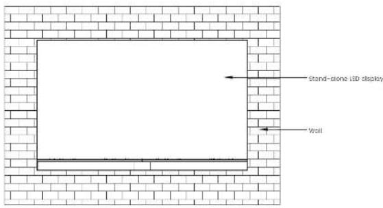
2.2 Installation dimensions

2-2,4
Installation Guide
| Remarks | ||||||
| Model No | L(mm) | H1(mm) | H2(mm) | W1(mm) | W2(mm) | W3(mm) |
| DV-12023W | 2678 | 1645.5 | 2259 | 19.8 | 802 | 40 |
| DV-15023W | 3344 | 2020 | 2633.5 19 | 8 802 | 40 | |
| DV-18023W | 4010 | 2394.56 | / | 19.8 | / | 40 |
Note: W1 and III are the installation dimensions of the Stand-alone LED display, W2 and H2 are the installation dimensions for base-mounting, and W3 are the installation dimensions for wall-mounting.
2.3 Steps for Installation
• 2.3.1 Base-installation
The parts and tools required for the installation of Stand-alone LED display are as follows:

Cross recessed pan head
tapping screws (M3, M4)

Hex key (5mm, 8mm)

Cross recessed countersunk head screws (M5)

Socket head cap screw
(M5, ME)

Gross recessed cheese
hand screws (M4)

Gross screwdriver
(almostar 0.3mm)

Cross screwdriver (diameter 3.5mm)
Step 1: install the upper and lower beams of the base. Use four M4 ^® 12 cross countersunk screws at the bottom of the beams and four M5 ^® 12 cross countersunk screws on the side to lighton end fix the upper and lower beams on the base with the junction plate.

Step 2: install the base. Insert the connecting shaft downward into the base, and fix the base, connecting shaft and lower beam with four M8 * 50 screws (Note: the side of the beam with M8 screw hole shall face to side A, while the M4 screw hole of the beam shall face down, and the direction of the beam and A-type support shall not be reversed).

Step 3: adjust casters. Turn the red handle, extend the support base to make it contact with the ground, fix the base to prevent the base from moving during the installation process, then insert the middle vertical bar on the base on the connecting shaft, and fix it with 8 M5 * 20 hexagon socket head screws on the inside (Note: the installation hole of the middle vertical bar faces side A).
2
2-2.4 —— Installation Guide

Step 4: Install the upper beam. Fix the upper beam and the middle vertical bar with two M8x20 hexagon screws.

Step 5: assemble the upper and lower back-mounted rack beams. Use four M5 * 12 cross recessed countersunk head screws to fix the T-shaped junction plate and the back-mounted rack beams.

2-2.4 — Installation Guide
Step 6: assemble the stud-link assembly of the back-mounted rock. Fix the upper and lower back-mounted rocks and the three middle vertical bar assembly on the T-shaped junction plate with M5+12 countersunk screws, fix and connect the sheet metal corner connector with the upper and lower back-mounted rocks with M5x10 cross recessed pan-head screw, and adjust the flatness of the back-mounted rock to avoid the occurrence of offset or staggered joints.

Step 7: assemble the back-mounted rock assembly and base. First install two step screws of the upper and lower back-mounted rock and then fix the whole back-mounted rock assembly into the U-shaped groove of the beam of the back-mounted rock through the stopped screws, and finally use eight M8 * 20 screws to fix the upper and lower back-mounted rock assembly with the middle vertical bar.

Step 8. assemble the lower beam assembly. Connect the lower beam (left) and lower beam (right) with junction plate, fix them with eight M5 * 8 pan head screws in the middle and four M4 * 6 cross recessed cheese head screws on the side (Note: the lower beam panel will not be installed temporarily).

2-2.4 —— Installation Guide
Step 9: fix the lower beam assembly and the back-mounted rack assembly. A total of six M5"75 screws are passed through 1,2 and 3 in the back-mounted rack to fix with the screw hole of M5 connecting block in the lower beam (Note: do not press the power cord and data line).

Step 10: install stepped screws on the cabinet frame. Secure the six stepped screws to the frame. (this step can be omitted if it has been installed firmly at the time of shipment)

Step II install the first row of cabinet frame, insert the cabinet frame with right border installed with HUB board into the U-shaped groove of back-mounted rock through stopped screw from right to left until the screw holes A, B, C and D on the cabinet frame are aligned with the four M5 screw holes on the back-mounted rocks. (Note: there are three kinds of cabinet frame; A-cabinet frame with left border, b-cabinet frame without border and C-cabinet frame with right border)

Step 12: install the second row of cabinet frame. Insert the cabinet frame into the U-shaped groove of back-mounted rock through stepped screw from left to right until the screw holes A, B, C and D on the frame are aligned with the four M5 screw holes on the back-mounted racks.

2-2.4 — Installation Guide
Step 13: refer to step 12 to install the remaining cabinet frame in turn (Note: the first column on the left is the cabinet frame with left border).

Step 14: install the decorative strips for plastic extrusion. Install decorative strips for plastic extrusion between two adjacent cabinet frames.

Step 15: connect the two adjacent columns of cabinet frames with three different magnet supports, and for them with M4 * 10 cross recessed pan hand tapping screws. At the same time, adjust the flatness of the cabinet frame during the installation process.

Step 15: fix the screws of A, B, C and D of the cabinet frame. Adjust the position of the cabinet frame. After the left and right sides of the cabinet frame are aligned with the left and right sides of the lower beam; fix each cabinet frame and the back-mounted rock with four M5 * 20 big flat-head screws.
Step 17: install the upper border (left) and upper border (right). Fix the upper border (left) and upper border (right) with M3*8 cross recessed pan hand tapping screws, as shown in the figure below.
2-2.4 — Installation Guide

Step 18: connect the power cord of Stond-alone LED display. Connect the block power cord to OND and the white power cord to VCC+, as shown in the figure below:

Step 19: connect the signal line of Stand-alone LED display. The signal line of Stand-alone LED display is shown in the figure below.

Step 20: install the lower beam panel. After the line test is normal, align the panel 1 and panel 2 with the U-shaped groove of the lower beam through back-off, and cover the panels on both sides of the lower beam.

Step 2: install the breathing LED board in the middle of the lower beam. Connect the flat cables with the breathing LED board and then attach the breathing LED board in the middle of the lower beam. At the same time, adjust the panel position on both sides of the lower beam.

Step 22: Install the LED panel. Take each HUB board as a unit, install 8 LED panels according to the correction barcode from left to right, and ensure that the arrow direction of the LED panel is upward during installation (Note: the last three serial numbers of the barcode are: 001, 002, 008).

natural_image
Line drawing of a flat-screen monitor mounted on a stand with supports (no text or symbols)2-2.4 — Installation Guide
Precoutions:
-
Please do not power on the cabinet during the connection of power cords and network cables to prevent the risk of electric shock
-
The voltage of this product is 100 - 240V, 50 / 60Hz. Please use the product within the specified power range to avoid fire or electric shock.
-
The power cord cannot be overloaded;
-
Please tighten the screws of the power cord to prevent the product from burning due to the excessive instantaneous current when power on, which may cause fire.
• 2.3.2 Wall-mounted installation
The parts and tools required for the wall-mounted cabinet are as follows:

Cross recessed pan head topping screens (M3 M4)

Hockey (term run)

Cross received countersunk head
screw (MS)

socket head cap screw (v5, v8)

Cross-recessed pan head screws (MB)

Cross-recessed cheese head screws (M4)

Cross screwdriver (diameter 53mm)

Cross screwdriver (diameter: 0.5mm)
Step 1: assemble the upper and lower back-mounted rack beams. Use four M5 * 12 cross recessed countersunk head screws to fix the T-shaped junction plate and the back-mounted rack beams.

Step 2: assemble the assembly of the back-mounted rack. Fix the upper and lower back-mounted racks and the three middle vertical bar assembly on the T-shaped junction plate with M5 * 12 countersunk screws, fix and connect the sheet metal corner connector with the upper and lower back-mounted racks with M5x10 cross recessed pan head screw, and adjust the flatness of the back-mounted rack at the same time.

Step 3: Install the book-mounted rack assembly. Fix the stud-link wall-mounted beam assembly on the wall with 16 MS screws (or expansion screws). (Notes: when installing 120-inch display, the wall can bear at least 290kg; when installing 150-inch display, the wall can bear at least 400kg; when installing 180-inch display, the wall can bear at least 530kg).

Step 4: complete the wall-mounted installation of Stand-alone LED display according to steps 8 to 22 of base installation
2-2.4 — Installation Guide
2.4 Segment Gap Adjustment of Display Module
After installation, if the whole display is not flat and/or there is any local segment gap, use a screwdriver (diameter 3.5mm) to adjust the corresponding magnet set. The maximum adjustable gap is 0.5mm. The unit LED panel has 8 adjustable positions of the magnet, which can adjust the magnet set from the front of display.
When adjusting the magnet from the front of display, remove the LED panel from the cabinet. Refer to 3.2 Front Maintenance for details of methods of LED panel removal.


3. MAINTENANCE
3.1 Precautions
- Before the maintenance of LED display, the power supply of the display must be cut off the power of the screen body during installation and maintenance to prevent electric shock and injury, and avoid short circuit of the live parts of the PCB board against the metal frame;
- Please pay attention to protect the module surface when using the front maintenance tools, and do not damage the module surface;
- Please pay attention to anti-static measures when using the front maintenance tools, and wear anti-static gloves to prevent static damage to LED;
- Please pay attention to the battery power before using the front maintenance tools;
- Pay attention to take out the module vertically to avoid damage and falling of LED lamp due to collision with edge of adjacent module.
- Vacuum front maintenance tools cannot work continuously for a long time. After taking out the module, please turn off the power supply of vacuum front maintenance tools in time to avoid burning out the motor.
3.2 Display maintenance
This product supports front LED panel maintenance. The tools required for front maintenance are vacuum front maintenance tools, as shown below:
3
3-3.4 Maintenance

| No.DescriptionRemarks | ||
| 1 | Rubber ring of sucker | Ensure good sealing |
| 2 | sucker | Seal between tools and LED panel |
| 3 | Charge socket | For battery charging |
| 4 | Handle | For holding bracket |
| 5 | ON/OFF | Switching power supply: "I" on; "O" off |
| 6 | Motor | For supply of suction |
The main process of front display maintenance is as follows:
Step 1: Turn off the power of the display;
Step 2: hold the handle with one hand, align and place the vacuum tool on the surface of the LCD panel, press the switch to set it to "f", and the tool will start to extract (Note: ensure that the vacuum power is sufficient to work);

Step 3. after about 3-5 seconds of air extraction, the vacuum sucker end the LED panel are tightly attached; Pull out the LED panel vertically by force. Hold the LED panel with one hand to prevent it from falling. Hold the vacuum sucker handle with the other hand. Make sure not to touch the adjacent LED panel when pulling out the LED panel, so as to avoid collision and damage to the LED.
Pull out the LED panel vertically

Step 4: move the IED panel to the safety plane, release the vacuum button, and set the switch to "0", that is, release the adsorption force and remove the tools. At this time, the IED panel HUB board and control card can be maintained.

Cleaning3.3
During the use of the product, dust or other stains may adhere to the surface of the LED Cabinet, affecting the effect of the display, so the display needs to be cleaned regularly to ensure that it is in the best effect.

Anti-static brush
The cleaning steps of the product are as follows:
Step 1: Turn off the power of the display;
Step 2: confirm the dirty place of the cabinet
Step 3: use the anti-static brush to wipe the dirty place, and use the air gun to blow the clean place at the same time.
Note:
-
Do not use industrial grease cleaning agent or scrubbing brush in cleaning process:
-
Take anti-static measures to prevent the static electricity from damaging the LED;
-
Pay attention to keep the same wiping direction:
3.4 Troubleshooting
| FAULTANALYSISOLUTION | ||
| blank screen. | Check if the display is powered on. | Power on. |
| Check the computer settings to ensure that the computer signal is output to the acquisition card (graphics card settings). | Correctly set the output mode of graphics card. | |
| Check whether the controller or indicator is working properly. | 1) Replace the network cable.2) Replace the controller.3) kapioca the scan card. | |
| Disordered screen picture. | Check whether the connection diagram is configured correctly. | Reconfigure the connection diagram correctly. |
| The consecutive LED cabinet does not light. | Check whether the unlighted LED cabinet is energised or whether the indicator light is normal. | 1) Check whether the unlighted LED cabinet's power supply is working properly.2) Check whether the first unlighted one is in good contact with the adjacent network cable.3) Replace the first unlighted LED cabinet's scan card and consult the customer service staff for professional repair service. |
| LED cabinet unit is black screen. | 1. Power Indicator is not working properly.2. The running indicator does not flash normally or is always on.3. The data cable is not connected properly.4.Poor contact of the external power cord of the product. | 1) Check the data line.2) Check the product's external power cord.3) Replace the switching power supply.4) Replace the product's system scan card. |
| FAULTANALYSISOLUTION | ||
| IFO unit product display is burned. | 1) data line is not connected property.2) The product a running program is lost. | 1) Recall the product configuration parameters in the existing Project file. Please contact customer service staff for details.2) Replace the product's internal scanning card, or re-upgrade the control card pro grom, please consult customer service for detailed operation. |
| IFO module has display failure. | 1) ILO failure, ICI failure.2) The module data port is loose and the contact is poor.3) Module a color correction data is lost.4) Data port of HUB card is poor contact. | 1) Replace the module and consult customer service staff for professional repair service.2) Replace the HUB card and consult the customer service staff for professional repair service. |

PACKING METHODS
The frame, A-type base and LED panel of Stand-alone LED display are packed separately.
One cabinet frame load-bearing carton can pack all the cabinet frames of Stand-alone LED display, and the packing methods are as follows:

The load-bearing carton of a cabinet frame can pack the back-mounted rack and vertical bar assembly of Stand-alone LED display, and the packing methods are as follows:

The load-bearing carton of a cabinet frame can pack the back-mounted rack and vertical bar assembly of Stand-alone LED display, and the packing methods are as follows:
4-4 Packing Methods

A load-bearing carton can pack the A-type support of Stand-alone LED display, and the packing methods are as follows:

Precautions: when unpacking the cabinet, take anti-static measures to prevent static electricity from damaging the LED.
5. CONTROL SYSTEM (optional)
5.1 interface
The interfaces of Stand-alone LED display are shown in the figure below:

InterfaceDescription
| Interface 1 | NC |
| Interface 2 | Sigabit Ethernet port used to connect external network to realize network interconnection |
| Interface 3 | USB3.0 interface, which can be used to access mouse, keyboard, U disk, Bluetooth speaker, transmitter and other equipment |
| Interface 4, 5 | HDMI interfaces, which are HDMI input source interfaces; HDMI and HDMI2 are used to provide audio and video signals |
| Interface 6, 7 | USB2.0 interface, which can be used to access mouse, keyboard, U disk, Bluetooth speaker, transmitter and other equipment |
| Interface 8 | AC power input of the display (Note: refer to the configuration of parameter table) |
| Interface 9 | POWUR_KEY switch, which is used to control the on-off of the display |
5
5-5.2 Control System
5.2 Software
To be updated.
6. TRANSPORTATION AND DELIVERY
6.1 Transportation
Packaged products are suitable for air, sea and land transportation. It is not allowed to be loaded in an open cabin or compartment during long-distance transportation. It is not allowed to be stored in an open storage during transshipment en route. It is not allowed to transfer together with flammable, explosive or perishable goods in a same vehicle (or other means of transport) in the transportation process. And the product is not allowed to suffer the wet or mechanical damage of rain, snow or other liquid substances.
6.2 Storage
When storing the product, it shall be stored in the original packing box. The storage environment of the product is 20–30°C. The relative humidity is <60%RH, and all kinds of harmful gases, flammable, explosive goods and corrosive chemicals are not allowed in the storage. And there shall be no strong mechanical vibrations, shocks and strong magnetic fields.
Note: Risk of damage to the device!
-
Attention should be paid to extreme changes in temperature when transporting the LED cabinet in cold weather. In this case, make sure that no water droplets (condensation) form on the device or inside the device. If condensation forms on the device, wait at least 12 hours before switching on the device.
-
Keep the storage environment ventilated if the LED cabinet is wet. After the LED cabinet is dry, put it back in the original box for storage.
6.3 Unpacking
Please note the following when unpacking:
- It is recommended Do Not discard the original packaging material. Please keep the original packaging materials for use when transporting the equipment again.
- Keep your documents in a safe place. This document is required for commissioning the device and is part of the device.
- Check the delivered equipment to look over if it has any significant damage during transit.
- Verify that the goods shipped contains complete equipment and accessories that you ordered separately. If there is any discrepancy or shipping damage, please contact customer service.
- Please store the documents in a safe place. This document is needed when presenting the equipment for debugging, and it is part of the equipment.
- The product should not be exposed to the installation site under construction for a long time other unpacking.
7. WARRANTY
- The guarantee period of the product is subject to the contract signed by both parties.
- Product failures caused by the following conditions are not covered by the guarantee.
- All human damage, self-modification, modification and upgrade online burning
- Exceeding the effective guarantee period and guarantee coverage; the guarantee is inconsistent, altered, or lost.
- Any damage caused by force majeure or guarantee changes.
- Excessive product loss or malfunction due to unsuitable environment of use.
- Other failures caused by reasons other than normal loss (normal loss refers to the loss of the product itself, parts and software systems, etc. that occur under the premise of this document.)
- Newline is not responsible for any personal property or other damages caused by the failure to follow contents of this document, including but not limited to instructions, procedures, specifications, warnings, etc.


- USER MANUAL
- SAFETY GUIDES
- IMPORTANT WARNINGS
- WARNING & CAUTION
- DANGER
- CAUTION
- QUALIFIED PROFESSIONAL
- SAFETY REGULATIONS
- DOCUMENT DESCRIPTION
- AGREEMENT
- DESCRIPTION
- OVERVIEW
- Features1.1
- Product and Accessories
- LED cabinet
- INSTALLATION GUIDE
- Attentions
- Installation dimensions
- Steps for Installation
- • 2.3.1 Base-installation
- • 2.3.2 Wall-mounted installation
- Segment Gap Adjustment of Display Module
- MAINTENANCE
- Precautions
- Display maintenance
- Cleaning3.3
- Troubleshooting
- PACKING METHODS
- CONTROL SYSTEM (optional)
- TRANSPORTATION AND DELIVERY
- Transportation
- Storage
- Unpacking
- WARRANTY
Brand : Newline
Model : DV-15023H
Category : Interactive screen