Velocity SI Pro - SSD ATP - Free user manual and instructions
Find the device manual for free Velocity SI Pro ATP in PDF.

User questions about Velocity SI Pro ATP
0 question about this device. Answer the ones you know or ask your own.
Ask a new question about this device
Download the instructions for your SSD in PDF format for free! Find your manual Velocity SI Pro - ATP and take your electronic device back in hand. On this page are published all the documents necessary for the use of your device. Velocity SI Pro by ATP.
USER MANUAL Velocity SI Pro ATP
2.2 Environment Specicaons....6
2.3 MIL-STD-810G Vibraon/Shock....6
2.4 IOPS ^1 6
2.5 Maximum Read/Write Performance....7
2.6 Electrical Characteristics....7
2.7 Reliability 7
2.8 Write/Erase Endurance ^1 8
2.9 Cercaon and compliance....8
3.0 SATA SSD Pin Assignment 8
3.1 Pin Locaon 8
3.2 Pin Assignment....9
4.0 Command Set 10
4.1 ATA Command Set....10
4.2 ATA Feature Set....12
4.3 Smart Informaon 12
4.3.1 Smart Command Sets....12
4.3.2 SMART Aribute 13
5.0 Mechanical Informaon.... 13
5.1 Physical Dimension Specicaons 13
5.2 Mechanical Form Factor (Units in mm) 14
Disclaimer
ATP Electronics Inc. shall not be liable for any errors or omissions that may appear in this document, and disclaims responsibility for any consequences resulting from the use of the informaon set forth herein.
ATP may make changes to specicaons and product descripons at any me, without noce. The informaon in this paper is furnished for informaonal use only so ATP assumes no responsibility or liability for any errors or inaccuracies that may appear in this document.
All parts of the ATP documentaon are protected by copyright law and all rights are reserved. This documentaon may not, in whole or in part, be copied, photocopied, reproduced, translated, or reduced to any electronic medium or machine-readable form without prior consent, in wring, from ATP Electronics, Inc.
The informaon set forth in this document is considered to be “Proprietary” and “Condenal” property owned by ATP.
© Copyright ATP all rights reserved.
Revision History
| Date | Version | Changes compared to previous issue |
| Jan 29 ^th , 2014 | 2.0 | - First Release |
| Feb 14 ^th , 2014 | 2.1 | - Update Safety Cercate |
| March 11 ^th , 2014 | 2.2 | - Update data retenon |
| April 14 ^th , 2014 | 2.3 | - Update the mechanical durability of SATA connector |
| Sept. 23 ^th , 2014 | 2.4 | - Update Power Protector descripon |
| Jan 8 ^th , 2015 | 2.5 | - Update Leer Head |
1.0 ATP Velocity SI Pro SATA SSD Overview
1.1 ATP Product Image
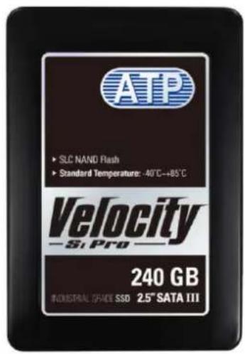
AF240GSSCJ-MABXX
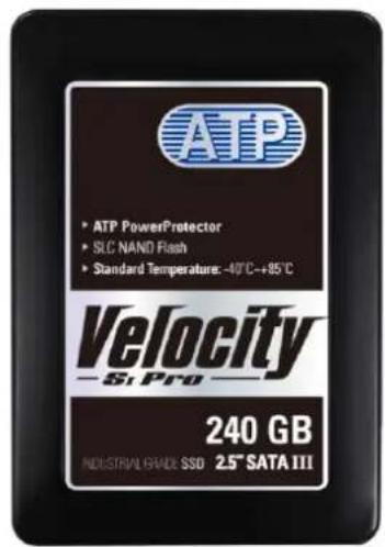
AF240GSSCJ-MABXP
Figure 1-1: ATP Product Image
Table 1-1: Capacies
| ATP P/N | CAPACITY | Power Protector |
| AF30GSSCJ-MABXX | 30GB | No |
| AF60GSSCJ-MABXX | 60GB | No |
| AF120GSSCJ-MABXX | 120GB | No |
| AF240GSSCJ-MABXX | 240GB | No |
| AF30GSSCJ-MABXP | 30GB | Yes |
| AF60GSSCJ-MABXP | 60GB | Yes |
| AF120GSSCJ-MABXP | 120GB | Yes |
| AF240GSSCJ-MABXP | 240GB | Yes |
Note: GB = 1,000,000,000 Byte
1.2 Introducon
ATP Velocity SI Pro 2.5" SSD is a best-in-class wide-temp industrial grade SLC SSD soluon with enterprise-class features. SI Pro SSD oers outstanding performance and proven reliability, ideal for extreme performance, high data security (AES 128 encrypon), and consistent data integrity requirement (ATP PowerProtector technology), suited for POS, industrial computers, data center and industrial applicaons exposed to mission crical, high shock and vibraon environments.
1.3 Main Features
● Capacity 30GB / 60GB / 120GB / 240GB
● SLC (Single Level Cell) NAND ash memory
● Operang temperature: -40^ to 85^
● Maximum performance: Sequenal read up to 505 MB/s, sequenal write up to 530 MB/s
- 2.5" form factor.
- 6Gb/s SATA V3.0 compliant and back compatible with SATA 1.5Gbps and SATA 3Gbps interface rate
● Hardware BCH ECC, correct up to 24-bit ECC per 1024 bytes of data
● Supports Nave Command Queue (NCQ)
● SMART funcon support by ATA CMD
● Support TRIM command (Windows 7 and up, latest Linux Kernel)
● Enhanced endurance by Global wear-leveling
● Power Protector, data integrity under power-cycling
● NSA Compliant Secure Erase
CE, FCC cercaon
● MIL-STD-810G Shock/Vibraon standard
ATP Industrial Grade SI Pro SATA SSD Specification Version 2.5

PowerProtector – Power Cycling Protection
The unstable power conditions of outdoor applications such as transportation, telecommunications/networking and embedded systems run the risk of data loss and drive corruption during a sudden power failure.
A standalone hardware design is the ideal configuration for power backup, ensuring a sufficient amount of reserve power during any power abnormalities and minimizing the consequent host re-designs for adding new features. During a sudden power failure, the abnormality is discovered by a power loss detection circuit and activates the power protection mechanism. The device then draws power from power protection reservoir, where the reserve power is stored. The reserve power gives enough time for the flash device to conclude the last writing command without losing any data.
2.0 Product Specicaon
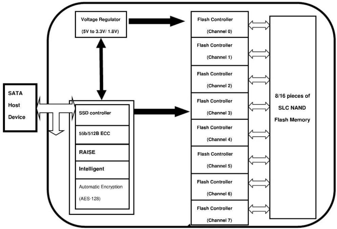
2.1 Block Diagram
ATP industrial grade SI Pro SATA SSD consists of below functional blocks. The advanced architecture is optimized to provide highest data reliability and transfer performance.
Figure 2-1:
flowchart
graph TD
    A["SATA Host Device"] --> B["SSD controller"]
    B --> C["55b/512B ECC"]
    B --> D["RAISE"]
    B --> E["Intelligent"]
    B --> F["Automatic Encryption (AES-128)"]
    C --> G["8/16 pieces of SLC NAND Flash Memory"]
    D --> G
    E --> G
    F --> G
    G --> H["Voltage Regulator (5V to 3.3V/1.8V)"]
    H --> I["Flash Controller (Channel 0)"]
    H --> J["Flash Controller (Channel 1)"]
    H --> K["Flash Controller (Channel 2)"]
    H --> L["Flash Controller (Channel 3)"]
    H --> M["Flash Controller (Channel 4)"]
    H --> N["Flash Controller (Channel 5)"]
    H --> O["Flash Controller (Channel 6)"]
    H --> P["Flash Controller (Channel 7)"]
    I <--> G
    J <--> G
    K <--> G
    L <--> G
    M <--> G
    N <--> G
    O <--> G
    P <--> G
2.2 Environment Specicaons
Table 2-1
| Type | Standard | |
| Temperature | Operang | -40°C to 85°C |
| Non-Operang | -40°C to 85°C | |
| Humidity | Operang | 25°C, 8% to 95%, noncondensing |
| Non-Operang | 40°C, 8% to 93%, noncondensing | |
| Vibraon | Operang | sine 16.4G, 10~2,000Hz |
| Shock | Operang | Half sine 1,500G/0.5ms |
| Altude | Operang | 80,000 feet Max. |
| Non-Operang | 80,000 feet Max. |
2.3 MIL-STD-810G Vibraon/Shock
Table 2-2
| Type | Value |
| Vibraon | A. MIL-STD-810G, Method 514.6 Procedure I, Category 20 (Ground Vehicles-ground mobile)B. MIL-STD-810G, Method 514.6 Procedure I, Category 14 (Rotary wing aircra-Helicopter)C. MIL-STD-810G, Method 514.6 Procedure I, Category 24 (General minimum integrity exposure) |
| Shock | MIL-STD-810G, Method 516.6, Procedure I40g, 11ms, terminal-peak saw tooth shock pulse |
2.4 IOPS ^1
Table 2-3
| Type | Value |
| 4K Random Read IOPS | Up to 7,000 IOPS |
| 4K Random Write IOPS | Up to 17,700 IOPS |
Note: Input/Output operaons per second tested by AS SSD on 120GB density.
2.5 Maximum Read/Write Performance
Table 2-4
| Type | 30GB | 60GB | 120GB | 240GB | |
| ATTO Disk Benchmark | Sequenal Read | 505 MB/s | 505 MB/s | 505 MB/s | 505 MB/s |
| Sequenal Write | 505 MB/s | 512 MB/s | 525 MB/s | 530 MB/s | |
| Crystal Disk Mark | Sequenal Read | 453 MB/s | 455 MB/s | 450 MB/s | 453 MB/s |
| Sequenal Write | 467 MB/s | 484 MB/s | 488 MB/s | 489 MB/s | |
2.6 Electrical Characteristics
Table 2-5
| Parameter | Symbol | Min | Typ | Max | Unit | Remark |
| Supply voltage | V_CC | 4.5 | 5.0 | 5.5 | V |
Table2-6
| Parameter | Symbol | Min | Typ | Max | Unit | Remark |
| Sustained write power | P_W | - | 2.15 | 2.45 | W | RMS value |
| Sustained read power | P_R | 2.11 | 2.10 | W | RMS value | |
| Idle power | P_S | - | 0.92 | 0.91 | W | RMS value |
2.7 Reliability
Table2-7
| Type | Value |
| MTBF (@ 25°C)1 | >2,000,000 hours |
| Data Retenon (@ 40 °C)2 | 10 years (with 10% P/E cycle) |
| SATA connector's Durability3 | 500 cycles minimum. (Plug latch inoperave) Operaon speed: maximum 200 cycles per hour. |
Notes:
1. The Mean Time between Failures (MTBF) is calculated using a predicon methodology, Telcordia SR-332, which based on reliability data of the individual components in the SI Pro. It assumes nominal voltage, with all other parameters within specified range.
2. Data retention value may vary across different temperature range and is experimental result to be used for reference.
3. The gures are based on EIA 364-09 standard to tested with backplane/blindmate applicaon.
2.8 Write/Erase Endurance ^1
Table 2-8
| Type | Value |
| Endurance Technology | Enhanced global dynamic and stac wear-leveling algorithmSLC ash block: 100,000 program/erase cycles |
| SSD Endurance | 30GB: 1,000 terabyte random write2,000 terabyte sequenal write60GB: 2,000 terabyte random write4,000 terabyte sequenal write120GB: 4,000 terabyte random write8,000 terabyte sequenal write240GB: 8,000 terabyte random write16,000 terabyte sequenal write |
Note: Endurance for the SI Pro can be predicted based on the usage conditions applied to the device, the internal NAND component cycles, the write amplicaon factor, and the wear leveling eciency of the drive. TBW may vary depending on applicaon, please contact ATP for TCO evaluaon if specific usage type applies.
2.9 Cercaon and compliance
Table 2-9
| Mark/Approval | Documentaon | Cercaon |
 | The CE marking (also known as CE mark) is a mandatoryconformance markon many products placed on the single market in theEuropean Economic Area(EEA). The CE marking ceres that a product has met EU consumer safety, health or environmental requirements. CE stands for Conformité Européenne, "European conformity" in French. | Yes |
 | FCC Part 15 Class B was used for Evoluon of United States (US) Emission Standards for Commercial Electronic Products, The United States (US) covers all types of unintentional radiators under Subparts A and B (Secons 15.1 through 15.199) of FCC 47 CFR Part 15, usually called justFCC Part 15 | Yes |
3.0 SATA SSD Pin Assignment
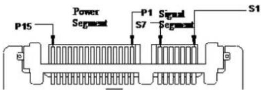
3.1 Pin Locaon
The following gure shows the pin locaon of the SI Pro SATA SSD, the connector is with both
signal and power segments.
Figure 3-1
3.2 Pin Assignment
There are total of 7 pins in the signal segment and 15 pins in the power segment. The pin denions are shown in Table 3-1
Table 3-1
| Group | Pin No.1 | Funcon | Descripon |
| Signal Segment | S1 | GND | Ground |
| S2 | A+ | Dierenal signal pair A | |
| S3 | A- | ||
| S4 | GND | Ground | |
| S5 | B- | Dierenal signal pair B | |
| S6 | B+ | ||
| S7 | GND | Ground | |
| Key & Spacing | |||
| Power Segment Power Segment | P1 | NC/V_33 | 3.3V power (Not used) |
| P2 | NC/V_33 | 3.3V power (Not used) | |
| P3 | NC/V_33 | 3.3V power (Not used) | |
| P4 | GND | Ground | |
| P5 | GND | Ground | |
| P6 | GND | Ground | |
| P7 | V5 | 5V power, pre-charge | |
| P8 | V5 | 5V power | |
| P9 | V5 | 5V power | |
| P10 | GND | Ground | |
| P11 | DAS | Device Acvity Signal | |
| P12 | GND | Ground | |
| P13 | NC/V12 | 12V power (Not used) | |
| P14 | NC/V12 | 12V power (Not used) | |
| P15 | NC/V12 | 12V power (Not used) | |
Note: All pins are in a single row, with a 1.27 mm (0.050") pitch.
4.0 Command Set
4.1 ATA Command Set
ATP industrial grade SI Pro SATA SSD support the commands show in the following table
Table 4-1
| Command | Op Code |
| NOP | 00h |
| DATA SET MANAGEMENT | 06h |
| RECALIBRATE | 10h |
| READ SECTORS | 20h |
| READ SECTORS WITHOUT RETRY | 21h |
| READ LONG | 22h |
| READ LONG WITHOUT RETRY | 23h |
| READ SECTOR(S) EXT | 24h |
| READ DMA EXT | 25h |
| READ NATIVE MAX ADDRESS EXT | 27h |
| READ MULTIPLE EXT | 29h |
| READ LOG EXT | 2Fh |
| WRITE SECTORS | 30h |
| WRITE SECTORS WITHOUT RETRY | 31h |
| WRITE LONG | 32h |
| WRITE LONG WITHOUT RETRY | 33h |
| WRITE SECTORS(S) EXT | 34h |
| WRITE DMA EXT | 35h |
| WRITE MULTIPLE EXT | 39h |
| WRITE DMA FUA EXT | 3Dh |
| WRITE LOG EXT | 3Fh |
| READ VERIFY SECTOR(S) | 40h |
| READ VERIFY SECTOR(S) (without Retry) | 41h |
| READ VERIFY SECTOR(S) EXT | 42h |
| WRITE UNCORRECTABLE EXT | 45h |
| READ LOG DMA EXT | 47h |
| WRITE LOG DMA EXT | 57h |
| READ FPDMA QUEUED | 60h |
| WRITE FPDMA QUEUED | 61h |
| SEEK | 70h |
| EXECUTE DEVICE DIAGNOTIC | 90h |
| INITIALIZE DEVICE PARAMETERS | 91h |
| DOWNLOAD MICROCODE | 92h |
| DOWNLOAD MICROCODE DMA | 93h |
| SMART | B0h |
| READ MULTIPLE | C4h |
| WRITE MULTIPLE | C5h |
| SET MULTIPLE MODE | C6h |
| READ DMA | C8h |
| READ DMA WITHOUT RETRIES | C9h |
| WRITE DMA | CAh |
| WRITE DMA WITHOUT RETRIES | CBh |
| WRITE MULTIPLE FUA EXT | CEh |
| STANDBY IMMEDIATE | E0h |
| IDLE IMMEDIATE | E1h |
| STANDBY | E2h |
| IDLE | E3h |
| READ BUFFER | E4h |
| CHECK POWER MODE | E5h |
| SLEEP | E6h |
| FLUSH CASH | E7h |
| WRITE BUFFER | E8h |
| READ BUFFER DMA | E9h |
| FLUSH CACHE EXT | EAh |
| WRITE BUFFER DMA | EBh |
| IDENTIFY DEVICE | ECh |
| SET FEATURES | EFh |
| SECURITY SET PASSWORD | F1h |
| SECURITY UNLOCK | F2h |
| SECURITY ERASE PREPARE | F3h |
| SECURITY ERASE UNIT | F4h |
| SECURITY FREEZE LOCK | F5h |
| SECURITY DISABLE PASSWORD | F6h |
| READ NATIVE MAX ADDRESS | F8h |
| SET MAX ADDRESS | F9h |
4.2 ATA Feature Set
| Feature | Support |
| 48-Bit Address feature set | YES |
| Advanced Power Management (APM) feature set | YES |
| General feature set | YES |
| General Purpose Logging (GPL) feature set | YES |
| Long Logical Sector (LLS) feature set non-512 | YES |
| Nave Command Queuing (NCQ) feature set | YES |
| Power Management feature set | YES |
| Power-Up In Standby (PUIS) feature set | YES |
| Security feature set | YES |
| S.M.A.R.T. feature set | YES |
| Soware Sengs Preservaon (SSP) feature set | YES |
| Write-Read-Verify feature set | YES |
4.3 Smart Informaon
4.3.1 Smart Command Sets
Table 4-3
| Command | Value (Hex) |
| Reserved | 00-CF |
| SMART read aributes | D0 |
| SMART enable/disable aribute autosave | D2 |
| SMART execute o-line immediate | D4 |
| SMART read log sector | D5 |
| SMART write log sector | D6 |
| SMART enable operaons | D8 |
| SMART disable operaons | D9 |
| SMART return status | DA |
| Reserved (Vendor Specific) | DC-FF |
4.3.2 SMART Aribute
Table 4-4
| ID | Value (Hex) | Aribute Name |
| 1 | 0x01 | Raw Read Error Rate |
| 5 | 0x05 | Rered RBlock Count |
| 9 | 0x09 | Power-On Hours |
| 12 | 0x0C | Device Power Cycle Count |
| 171 | 0xAB | Program Fail Count |
| 172 | 0xAC | Erase Fail Count |
| 174 | 0xAE | Unexpected Power Loss |
| 177 | 0xB1 | Wear Range Delta |
| 181 | 0xB5 | Program Fail Count |
| 182 | 0xB6 | Erase Fail Count |
| 187 | 0xBB | Reported Uncorrectable Errors |
| 194 | 0xC2 | Temperature |
| 195 | 0xC3 | On-the-y ECC Count |
| 196 | 0xC4 | Reallocaon Event Count |
| 201 | 0xC9 | Uncorrectable So Read Error Rate |
| 204 | 0xCC | So ECC Correcon Rate |
| 230 | 0xE6 | Drive Life Protecon Status |
| 231 | 0xE7 | Remaining SSD Life |
| 241 | 0xF1 | Lifetime Writes from Host (GB) |
| 242 | 0xF2 | Lifetime reads from Host (GB) |
5.0 Mechanical Informaon
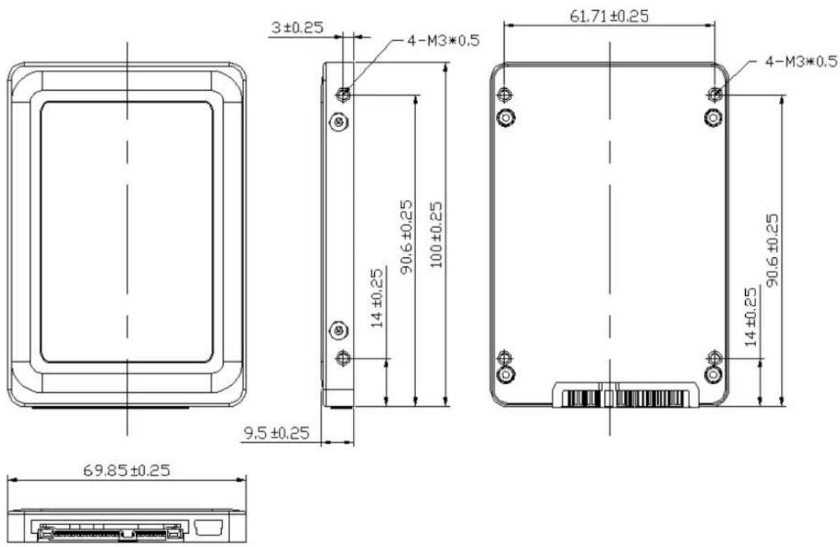
5.1 Physical Dimension Specicaons
Table 5-1
| Type | Value | |
| SI PRO SATA SSD | Length | 100.00 mm +/- 0.25mm |
| Width | 69.85 mm +/- 0.25 mm | |
| Thickness | 9.5 mm +/- 0.25mm | |
5.2 Mechanical Form Factor (Units in mm)
ATP TAIWAN(HQ)
TEL: +886-2-2659-6368
FAX: +886-2-2659-4982
sales-apac@atpinc.com
ATP USA
TEL: +1-408-732-5000
FAX: +1-408-732-5065
sales@atpinc.com
ATP JAPAN
TEL: +81-03-6206-8097
FAX: +81-03-6206-8098
sales-japan@atpinc.com
ATP EUROPE
TEL:+49-89-374-9999-0
FAX: +49-89-374-9999-29
sales-europe@atpinc.com
ATP CHINA
TEL: +86-21-5080-2220
FAX: +86-21-5080-2219
sales@cn.atpinc.com
www.atpinc.com