SIM984 - Measurement SRS - Free user manual and instructions
Find the device manual for free SIM984 SRS in PDF.

User questions about SIM984 SRS
0 question about this device. Answer the ones you know or ask your own.
Ask a new question about this device
Download the instructions for your Measurement in PDF format for free! Find your manual SIM984 - SRS and take your electronic device back in hand. On this page are published all the documents necessary for the use of your device. SIM984 by SRS.
USER MANUAL SIM984 SRS
Revision1.13• March11,2013
Certification
StanfordResearchSystemscertifiesthatthisproductmetitspublishedspecificationsatthetime ofshipment.
Warranty
ThisStanfordResearchSystemsproductiswarrantedagainstdefectsinmaterialsandworkmanshipforaperiodofone(1)yearfromthedateofshipment.
Service
Forwarrantyserviceorrepair, thisproductmustbereturnedtoaStanfordResearchSystems authorizedservicefacility.ContactStanfordResearchSystemsoranauthorizedrepresentative beforereturningthisproductforrepair.
Informationinthisdocumentissubjecttochangewithoutnotice.
Copyright © StanfordResearchSystems, Inc., 2013. Allrightsreserved.
StanfordResearchSystems, Inc.
1290-DReamwoodAvenue
Sunnyvale, CA94089 USA
Phone:(408)744-9040• Fax:(408)744-9049
www.thinkSRS.com• e-mail:info@thinkSRS.com
PrintedinU.S.A.Documentnumber9-01691-903
Contents
GeneralInformationiii
Symbols......iv
Notation......v
Specifications......vi
1GettingStarted1-1
1.1 Introduction to the Instrument......1-2
1.2Front-PanelOperation....1-2
1.3SIMInterface....1-4
2RemoteOperation2-1
2.1IndexofCommonCommands....2-2
2.2AlphabeticListofCommands ......2-3
2.3Introduction 2-4
2.4Commands 2-4
2.5StatusModel 2-13
3Circuitry
3.1 CircuitDescriptions ......3-2
3.2SchematicDiagrams....3-3
3-1
GeneralInformation
TheSIM984IsolationAmplifier, part of Stanford Research Systems' Small Instrumentation Modules family, is a wide bandwidth, low noise isolation amplifier for use with analog signals from DC to 1 MHz.
Service
Donotinstallsubstitutepartsorperformanyunauthorizedmodificationstothisinstrument.
TheSIM984isasingle-widemoduledesignedtobeusedinsidethe SIM900Mainframe.Donotturnonthepoweruntilthemoduleis completelyinsertedintothemainframeandlockedinplace.
SymbolsyoumayFindonSRSProducts
| Symbol Description | |
 | Alternating current |
 | Caution - risk of electric shock |
 | Frame or chassis terminal |
 | Caution - refer to accompanying documents |
 | Earth (ground) terminal |
 | Battery |
 | Fuse |
| On (supply) | |
| Off (supply) | |
Notation

WARNING

CAUTION
The following notation will be used throughout this manual.
A warning mean that injury or death is possible if the instructions are not obeyed.
Acautionmeansthatdamagetotheinstrumentorotherequipment is possible.
Typesetting conventions used in this manual are:
- Front-panelbuttonsaresetas[Button].
- Front-panelindicatorsaresetasOverload.
- Remotecommandnamesaresetas*IDN?
- LiteraltextotherthancommandnamesissetasOFF.
Remotecommandexampleswillallbesetinmonospacedfont.In theseexamples,datasentbythehostcomputertotheSIM984areset asstraightteletypefont,whileresponsesreceivedbythehost computerfromtheSIM984aresetasslantedteletypefont.
Specifications
PerformanceCharacteristics
| Isolationvoltage±1000V(max) | |
| Leakagecurrent<2μAat1000Vdc | |
| Isolationcapacitance1000pF | |
| IsolationModeRejectionRatio(IMRR)150dBatDC | |
| Maximuminput±10V | |
| Inputimpedance1MΩ | |
| Inputnoise(typ.)15nV/ √Hz@1kHz | |
| Inputoffsetdrift3μV/ °C(typ.) | |
| Outputvoltagerange±10V | |
| Outputcurrent±20mA(max.) | |
| Outputresistance50Ω | |
| Outputoffset±0.1V,adjustable | |
| Outputoffsetdrift1mV/ °C(typ.) | |
| Outputnoise(typ.)80μVrms(100Hzbandwidth) | |
GeneralCharacteristics
| InterfaceSerial(RS-232)throughSIMinterface | |
| Connectorsbananajack(2front) | |
| Weight1.5lbs | |
| Dimensions1.5 " W× 3.6H× 7.0 D |
1GettingStarted
Thischaptergivesyouthenecessaryinformationtogetstarted quicklywiththeSIM984IsolationAmplifier.
InThisChapter
1.1 Introduction to the Instrument......1-2
1.1.1Overview....1-2
1.1.2 Power-onState....1-2
1.2Front-PanelOperation....1-2
1.2.1 Inputs....1-2
1.2.2Gain....1-2
1.2.3Bandwidth....1-3
1.2.4Output....1-3
1.3SIMInterface....1-4
1.3.1SIMinterfaceconnector....1-4
1.3.2 Directinterfacing......1-5
1.1 Introduction to the Instrument
TheSIM984IsolationAmplifierisalow-noise, programmablegain amplifierforisolatinganalogsignalsfromDCto1MHz.
1.1.1 Overview
The basic function of the SIM984 istoisolate and (possibly) amplify an analog signal. The input presents a 1MΩ impedance between the red and black bananajacks, but high impedance (floating) between each input jack and chassis ground. A maximum of ±1000V dccan be between neither jack and ground, but the potential between the input jacks must be less than ±10V. The input is DC coupled.
A gain of ×1, ×10, or ×100 can be set from the front panel. The output bandwidth this also adjustable from the front panel, with three choices of high-frequency cut-off: 100Hz, 10kHz, and 1MHz. Finally, the output DC offset can be trimmed using athinscrew driver accessing the "Offset" holeneartheoutputBNC.
1.1.2 Power-onState
TheSIM984storesitsoperationstate(gainandbandwidthconfiguration)innon-volatilememory.Atpower-on,theSIM984willreturntoitspreviousconfigurationafterabriefsystemcheckandinitialization.
1.2 Front-Panel Operation
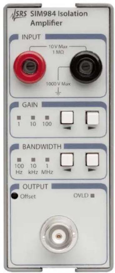
ThefrontpaneloftheSIM984(seeFigure1.1)providesasimple operatorinterface.
1.2.1 Inputs
TheinputtotheSIM984isthroughtheredandblackbananajacksin thefront-panel"INPUT"block.

WARNING
Thebananajacksareisolatedfromthechassisforusewithinsulated testleads. IftheuserconnectsaBNC-to-Bananaadaptortothe SIM984toallowinputsfromaBNC-terminatedcable,itiscritical thatnodangerousvoltagesbeappliedtothecable,astheexposed shieldoftheinputBNCcouldcreateanelectricalhazard.
1.2.2Gain
User gain settings of ×1, ×10, and ×100, are selected with the left and right[Gain]buttons.
text_image
SRS SIM984 Isolation Amplifier INPUT 10 V Max 1 MΩ 1000 V Max GAIN 1 10 100 BANDWIDTH 100 10 1 Hz kHz MHz OUTPUT Offset OVLD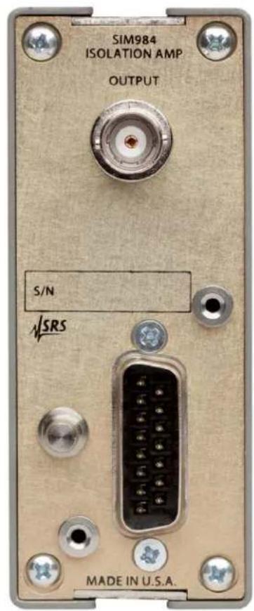
text_image
SIM984 ISOLATION AMP OUTPUT S/N ✓SRS MADE IN U.S.A.Figure1.1:TheSIM984frontandrearpanels.
1.2.3Bandwidth
UserbandwidthsettingsofDC-100Hz,DC-10kHz,andDC-1MHz arewiththeleftandright[Bandwidth]buttons.
1.2.4Output
Theamplified,band-limitedsignalappearsatthe(ground-referenced) BNCconnectorsonthefrontandrearpanels.Eachoutputconnectionisthrougha50Ωresistor.Fornormaloperation,theusershould notneedtoterminatetheoutput.Ifa50Ωterminationisapplied, theoutputsignalwillbedividedinhalf.
If the output signals exceed ±10V, the output overload detection is activated. This is indicated by the OVL D near the top of the "OUTPUT" block on the front panel.
TheSIM984outputoffsetvoltagemaybetrimmedbyadjustingthe
outputoffsetthroughthefront-panelaccessholeinthe"OUTPUT" block.
1.3SIMInterface
The primary connection to the SIM984 Isolation Amplifier is therear-panel DB-15 SIM interface connector. Typically, the SIM984 is mated to a SIM900 Mainframe viathis connection, either through one of the internal Mainframeslots, or theremotecable interface.
ItisalsopossibletooperatetheSIM984directly, without using the SIM900Mainframe. Thissectionprovidesdetailsontheinterface.

CAUTION
TheSIM984hasnointernalprotectionagainstreversepolarity,missing supply,orovervoltageonthepowersupplypins.Misapplicationofpower maycausecircuitdamage.SRSrecommendsusingtheSIM984together withtheSIM900Mainframeformostapplications.
1.3.1 SIMinterfaceconnector
TheDB-15SIMinterfaceconnectorcarriesallthepowerandcommunicationslinestotheinstrument.Theconnectorsignalsarespecified inTable1.1
| PinSignalSrc | DestDescription | Direction | |
| 1 | SIGNAL_GND | MF SIM | Ground reference for signal |
| 2 | -STATUS | SIM MF | Status/service request (GND = asserted, +5 V=idle) |
| 3 | RTS | MF SIM | HW handshake (not used in SIM984) |
| 4 | CTS | SIM MF | HW handshake (not used in SIM984) |
| 5 | -REF_10MHZ | MF SIM | 10 MHz reference (no connection in SIM984) |
| 6 | -5 V | MF SIM | Power supply (no connection in SIM984) |
| 7 | -15 V | MF SIM | Power supply |
| 8PSRTN | MF SIM | Powersupplyreturn | |
| 9CHASSISGND | Chassisground | ||
| 10 | TXD | MF SIM | Async data (start bit = “0”= +5 V; “1” = GND) |
| 11 | RXD | SIM MF | Async data (start bit = “0”= +5 V; “1” = GND) |
| 12 | +REF_10MHz | MF SIM | 10 MHz reference (no connection in SIM984) |
| 13 | +5 V | MF SIM | Power supply |
| 14 | +15 V | MF SIM | Power supply |
| 15 | +24 V | MF SIM | Power supply |
Table1.1:SIMInterfaceConnectorPinAssignments,DB-15
1.3.2 Directinterfacing
TheSIM984isintendedforoperationintheSIM900Mainframe, but usersmaywishtodirectlyinterfacethemoduletotheirownsystems withouttheuseofadditionalhardware.
ThematingconnectorneededisastandardDB-15receptacle,such asAmppart#747909-2(orequivalent).Clean,well-regulatedsupply voltages of ± 15, + 5 and +24 VDC must be provided, following thepin-outspecifiedinTable1.1.Groundmustbeprovidedon pins1and8,withchassisgroundonpin9.The-STATUSsignal maybemonitoredonpin2foralow-goingTTL-compatibleoutput indicatingastatusmessage.
1.3.2.1 Directinterfacecabling
If the user intend stodirectly wire the SIM984 independent of the SIM900 Mainframe, communication is usually possible by directly connecting the appropriate interfacelines from the SIM984DB-15 plug to the RS-232 serial port of a personal computer. ^1 Connect RXD from the SIM984 directly to R Don the PC, TX D directly to TD. In other words, anull-modem styleable is not needed.
TointerfacedirectlytotheDB-9male(DTE)RS-232porttypically foundonpersonalcomputers,acablemustbemadewithafemale DB-15sockettomatewiththeSIM984,andafemaleDB-9socket tomatewiththePC'sserialport. SeparateleadsfromtheDB-15 needtogotothepowersupply,makingwhatissometimesknowas a"hydra"cable.Thepin-connectionsaregiveninTable1.2.
1.3.2.2 Serialsettings
The initial serial port settings at power-on are: 9600 Baud, 8-bits, noparity, 1 stopbit, and no flow control. The serial baud rate and word size are fixed, but the parity may be changed with the PARI command.
DB-15/FtoSIM984Name
DB-9/F
10←→ 3TxD
11←→ 2RxD
5ComputerGround
toP/S
7←→ -15VDC
13←→ +5VDC
14←→ +15VDC
15←→ +24VDC
8,9←→ Ground(P/Sreturncurrent)
1←→ SignalGround(separatewiretoGround)
Table1.2:SIM984DirectInterfaceCablePinAssignments
2RemoteOperation
ThischapterdescribesoperatingtheSIM984overtheserialinterface.
InThisChapter
2.1IndexofCommonCommands......2-2
2.2AlphabeticListofCommands....2-3
2.3Introduction....2-4
2.3.1 Power-onconfiguration....2-4
2.3.2Buffers....2-4
2.3.3DeviceClear....2-4
2.4Commands....2-4
2.4.1CommandSyntax....2-5
2.4.2 Notation .....2-6
2.4.3Examples 2-6
2.4.4AmplifierCommands ......2-7
2.4.5StatusCommands....2-7
2.4.6InterfaceCommands....2-9
2.5StatusModel 2-13
2.5.1StatusByte(SB)....2-13
2.5.2ServiceRequestEnable(SRE) .....2-14
2.5.3 Standard Event Status (ESR) ..... 2-15
2.5.4 StandardEventStatusEnable(ESE).....2-15
2.5.5CommunicationErrorStatus(CESR) .....2-15
2.5.6CommunicationErrorStatusEnable(CESE) .2-16
2.1 IndexofCommonCommands
| symboldefinition |
| i,jIntegers |
| zLiteraltoken |
| (?)Requiredforqueries;illegalforsetcommands |
| varparameteralwaysrequired |
| {var} requiredparameterforsetcommands;illegalforqueries |
| [var]optionalparameterforbothsetandqueryforms |
Amplifier
| GAIN(?){i} | 2-7Gain | |
| BWTH(?) {i} | 2-7 | Bandwidth |
Status
| *STB?[i] | 2-7StatusByte |
| *SRE(?) [i,] {j} | 2-7 Service Request Enable |
| *CLS | 2-7ClearStatus |
| *ESR?[i] | 2-8StandardEventStatus |
| *ESE(?) [i,] {j} | 2-8 Standard Event Status Enable |
| CESR?[i] | 2-8CommErrorStatus |
| CESE(?) [i,]{j} | 2-8 Comm Error Status Enable |
| OVLD? | 2-8OverloadCondition |
| PSTA(?) {z} | 2-9 Pulse -STATUS Mode |
Interface
| *RST | 2-9Reset |
| *IDN? | 2-9Identify |
| *OPC(?) | 2-9OperationComplete |
| CONS(?) {z} | 2-10 Console Mode |
| LEXE? | 2-10 ExecutionError |
| LCME? | 2-11 CommandError |
| PARI(?) {z} | 2-11 Parity |
| TOKN(?) {z} | 2-11 Token Mode |
| TERM(?) {z} | 2-12 Response Termination |
2.2AlphabeticListofCommands
★
*CLS2-7ClearStatus
*ESE(?) [i,] {j} 2-8 Standard Event Status Enable
*ESR?[i]2-8StandardEventStatus
*IDN?2-9Identify
*OPC(?)2-9OperationComplete
*RST2-9Reset
*SRE(?) [i,] {j} 2-7 Service Request Enable
*STB?[i]2-7StatusByte
B
BWTH(?) {i} 2-7 Bandwidth
C
CESE(?) [i,]{j} 2-8 Comm Error Status Enable CESR?[i] 2-8CommErrorStatus CONS(?) {z} 2-10 Console Mode
G
GAIN(?) {i} 2-7 Gain
L
LCME? 2-11 CommandError LEXE? 2-10 ExecutionError
0
OVLD? 2-8OverloadCondition
P
PARI(?) {z} 2-11 Parity PSTA(?) {z} 2-9 Pulse -STATUS Mode
T
TERM(?) {z} 2-12 Response Termination TOKN(?) {z} 2-11 Token Mode
2.3 Introduction
RemoteoperationoftheSIM984istroughasimplecommandlanguagedocumentedinthischapter.Bothsetandqueryformsof mostcommandsaresupported,allowingtheusercompletecontrol oftheisolationamplifierfromaremotecomputer,eitherthroughthe SIM900MainframeordirectlyviaRS-232(seeSection1.3.2.1).
2.3.1 Power-onconfiguration
Thesettingsfortheremoteinterfaceare9600baudwithnoparity andnoflowcontrol,andlocalechodisabled(CONS0FF).
MostoftheSIM984instrumentsettingsarestoredinnon-volatile memory, andatpower-ontheinstrumentreturnstothestateitwas lastinwhenpowerwasremoved.Exceptionsarenotedinthecommanddescriptions.
Resetvaluesofparametersareshowninboldface.
2.3.2Buffers
Incomingdatafromthehostinterfaceisstoredina32-byteinput buffer. Charactersaccumulateintheinputbufferuntilacommand terminator (either CR or LF ) is received, at which point the messageis parsedandexecuted.QueryresponsesfromtheSIM984are bufferedina32-byteoutputqueue.
If the input buffer overflows, then all data in both the input buffer and the output queue are discarded, and an error is recorded in the CESR and ESR status registers.
2.3.3DeviceClear
TheSIM984hostinterfacecanbeasynchronouslyresettoitspower-on configuration by sending an RS-232-style (break) signal. From theSIM900Mainframe, thisisaccomplished with the SIM900SRST command; if directly interfacing via RS-232, then use a serial break signal. After receiving the Device Clear, the interface is reset and CONS mode is turned 0FF. Note that this only resets the communication interface; the basic function of the SIM984 is left unchanged; toreset the instrument, see *RST.
2.4 Commands
Thissectionprovidessyntaxandoperationaldescriptionsforreomotecommands.
2.4.1 CommandSyntax
The four letter mnemonic (shown in CAPS) in each command sequence specifies the command. Therest of these sequence consists of parameters.
Commandsmaytakeeithersetorqueryform,dependingonwhether the“?”characterfollowsthemnemonic.Setonlycommandsare listed without the “?”, query only commands show the “?” after the mnemonic,andoptionallyquerycommandsaremarkedwitha“(?)”.
Parametersshownin{ }and[]arenotalwaysrequired.Parametersin{ }arerequiredtosetavalue,andareomittedforqueries.Parameters in[]arcoptionalinbothsetandquerycommands.Parameterslisted withoutanysurroundingcharactersarealwaysrequired.
Donotsend()or{ } or[]aspartofthecommand.
Multipleparametersareseparatedbycommas.Multiplecommands maybesentononecommandlinebyseparatingthemwithsemicolons(;)solongastheinputbufferdoesnotoverflow.Commands are terminated by either CR or LF characters. Null commands andwhitespaceareignored. Executionofcommand(s)doesnot beginuntilthecommandterminatorisreceived.
tokens Token parameters (generically shown as z in the command descriptions) can be specified either as a key word or integervalue. Command descriptions list the valid keyword options, with each keyword followed by its corresponding integervalue. Forexample, to set the response termination sequence to CR + LF , the following two commands are equivalent:
TERM CRLF —or— TERM 3
Forqueriesthatreturntokenvalues,thereturnformat(keywordor integer)isspecifiedwiththeTOKNcommand.
2.4.2 Notation
The following tables summarize the notation used in the command descriptions:
symboldefinition
i,jIntegers
zLiteraltoken
(?)Requiredforqueries;illegalforsetcommands
varparameteralwaysrequired
{var} requiredparameterforsetcommands;illegalforqueries
[var]optionalparameterforbothsetandqueryforms
2.4.3Examples
Each command is provided with a simple example illustrating its usage. In these examples, all datasent by the host computerto the SIM984 are set as straight teletype font, while responses received the host computer from the SIM984 are set as slanted teletype font.
Theusageexamplesvarywithrespecttoset/query,optionalparameters,andtokenformats. Theseexamplesarenotexhaustive,butare intended to provide a convenient starting point for user programming.
2.4.4AmplifierCommands
| GainGAIN(?){i}Set (query) input gain {to state i=(0 (×1), 1 (×10), 2 (×100))}.GAIN2 | |
| 2.4.5StatusCommands | BandwidthBWTH(?){i}Set (query) the signal bandwidth {to state i=(0 (DC-100 Hz), 1 (DC-10kHz),2(DC-1MHz))}.BWTH?Example:1TheStatuscommandsqueryandconfigureregistersassociatedwith statusreportingoftheSIM984. |
| StatusByte*STB?[i]ReadstheStatusByteregister[biti].Executionofthe*STB?query(withouttheoptionalbiti)always causes the -STATUS signal to be deasserted. Note that *STB? i will not clear -STATUS, even if bit i is the only bit presently causing the -STATUSsignal.SeealsothePSTAcommand.TheOVLDbitin*STBiscleareduponreading.*STB?Example:1 | |
| *SRE(?) [i,] {j} | Service Request EnableSet (query) the Service Request Enable register [bit i] {to j}.Example:*SRE0,1 |
| *CLS | ClearStatus*CLS immediately clears the ESR, CESR, and the OVLD bit in the StatusByte.Example:*CLSStandardEventStatus*ESR?[i]ReadstheStandardEventStatusRegister[biti].Uponexecuting*ESR?,thereturnedbit(s)oftheESRregisterare cleared.*ESR?Example:64 |
| *ESE(?) [i,]{j} | Standard Event Status EnableSet (query) the Standard Event Status Enable Register [bit i] {to j}.*ESE6,1Example:ESE?64 |
| CommErrorStatusCESR?[i]QueryCommErrorStatusRegister[forbiti].UponexecutingaCESR?query,thereturnedbit(s)oftheCESR registerarecleared.CESR?Example:0 | |
| CESE(?) [i},{j} | Comm Error Status EnableSet (query) Comm Error Status Enable Register [for bit i] {to j}CESE?Example:0 |
| OVLD? | OverloadConditionQueryOverloadCondition. IftheSIM984isoverloading,OVLD? returns1;otherwise0.OVLD?Example:0 |
| PSTA(?) {z} | Pulse -STATUS ModeSet (query) the Pulse -STATUS Mode {to z=(OFF 0, ON 1)}.When PSTA ON is set, any new service request will only pulse the -STATUSsignallow(foraminimumof1μs).Thedefaultbehavior istolatch-STATUSlowuntila*STB?queryisreceived.Atpower-on,PSTAassettoOFF.PSTA?Example:OFF |
2.4.6InterfaceCommands
| InterfacecommandsprovidegenericcontrolovertheinterfacebetweentheSIM984andthehostcomputer. | |
| Reset*RSTResettheSIM984todefaultconfiguration.After*RST,thegainissetto×1andthebandwidthtoDC-100Hz.Thisisequivalenttothefollowingcommandsequence:GAIN0;BWTH0 | |
| Example: | *RST |
| *IDN? | IdentifyReadthedeviceidentificationstring.Theidentificationstringisformattedas:StanfordResearchSystems, SIM984,s/n******,ver#.#where*****isthe6-digitserialnumber,and#.#isthefirmware revisionlevel.*IDN?Example:StanfordResearchSystems, SIM984,s/n003075,ver1.02 |
| *OPC(?) | OperationCompleteOperationComplete.SetstheOPCflagintheESRregister.The query form *OPC? writes a 1 in the output queue when complete,butdoesnotaffecttheESRregister. |
| Example: | *OPC |
ConsoleModeCONS(?){z}
Set (query) the Console mode {to z=(OFF 0, ON 1)}.
CONScauseseachcharacterreceivedattheInputBuffertobecopied totheOutputQueue.
Atpower-onandDevice-Clear, CONSissettoOFF.
CONS?Example:
0
ExecutionErrorLEXE?
Querythelastexecutionerrorcode.AqueryofLEXE?alwaysclears theerrorcode,soasubsequentLEXE?willreturn0. Validcodesare:
ValueDefinition
0NoexecutionerrorsincelastLEXE?
1Illegalvalue
2Wrongtoken
3Invalidbit
16Commandnotready
*STB?12;LEXE?;LEXE?Example:
3
0
Theerror(3,"Invalidbit,")isbecause*STB?onlyallowsbit-specific queriesof0-7.ThesecondreadofLEXE?returns0.
| CommandErrorLCME?Querythelastcommanderrorcode.AqueryofLCME?alwaysclearstheerrorcode,soasubsequentLCME?willreturn0. Validcodesare:ValueDefinition | |
| 0NoexecutionerrorsincelastLCME?1Illegalcommand2Undefinedcommand3Illegalquery4Illegalset5Missingparameter(s)6Extraparameter(s)7Nullparameter(s)8Parameterbufferoverflow9Badfloating-point10Badinteger11Badintegertoken12Badtokenvalue13Badhexblock14Unknowntoken*IDNExample:LCME?4Theerror(4,"Illegalset")isduetothemissing"?". | |
| ParityPARI(?){z}Set (query) parity {to z = (NONE 0, ODD 1, EVEN 2, MARK 3, SPACE 4)}.Afterpower-on,modulesdefaulttoPARINONE. | |
| Example: | PARI EVEN |
| TOKN(?) {z} | Token ModeSet (query) the Token Query mode {to z=(OFF 0, ON 1)}.If TOKN ON is set, then queries to the SIM module that return tokenswillreturnthetextkeyword;otherwisetheyreturnthedecimal integervalue.Thus, the only possible responses to the TOKN? query are ON and 0.On reset, TOKN is set to OFF. |
| Example: | TOKN OFF |
ResponseTerminationTERM(?){z}
Set (query) the term sequence {to z=(NONE 0, CR 1, LF 2, CRLF 3, LFCR 4) }. The term sequence is appended to all query responses sentbythemodule, and is constructed of ASCII character(s)13(carriagereturn)and10(linefeed). Thetokenmnemonicgivesthe sequenceofcharacters.
Atpower-on, TERMissettoCRLF.
TERM?Example:
3
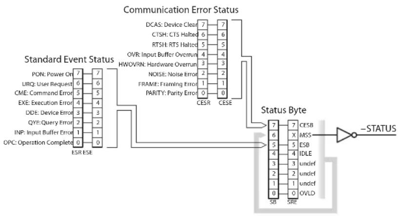
2.5StatusModel
TheSIM984statusregistersfollowthehierarchicalIEEE-488.2format.AblockdiagramofthestatusregisterarrayisgiveninFigure2.1.
TherearetwocategoriesofregistersintheSIM984statusmodel:
EventRegisters: Theseread-only registers record the occurrence of defined events. Whenthe event occurs, the corresponding bit is set to 1. Upon querying an event register, any set bits within it are cleared. These are sometimes known as "sticky bits," since once set, a bit can only be cleared by reading its value. Event register names end with SR.
Enable Registers: These read/write registers define a bitwise mask for their corresponding event register. If any bit position is set in an event registerwhilethesamebitpositionisalsosetintheenable register,thenthecorrespondingsummarybitmessageisset. Enableregister namesendwithSE.
The Status Byte is the top-level summary of the SIM984 status model. When masked by the Service Request Enable register, a bit set in the StatusBytecausesthe-STATUSsignaltobeassertedontherear-panelSIMinterfaceconnector.
Typically, -STATUS remains asserted(low) until a *STB? query is received, at which time -STATUS is deasserted (raised) ^1 . Afterclearing the -STATUS signal, it will only be re-asserted in response to a
flowchart
graph TD
    A["Standard Event Status"] --> B["PON: Power On 7"]
    A --> C["URQ: User Request 6"]
    A --> D["CME: Command Error 5"]
    A --> E["EXE: Execution Error 4"]
    A --> F["DDE: Device Error 3"]
    A --> G["QYE: Query Error 2"]
    A --> H["INP: Input Buffer Error 1"]
    A --> I["OPC: Operation Complete 0"]
    A --> J["ESR ESE 7"]
    K["Communication Error Status"] --> L["DCAS: Device Clear 7"]
    K --> M["CTSH: CTS Halted 6"]
    K --> N["RTSH: RTS Halted 5"]
    K --> O["OVR: Input Buffer Overrun 4"]
    K --> P["HWOVRN: Hardware Overrun 3"]
    K --> Q["NOISE: Noise Error 2"]
    K --> R["FRAME: Framing Error 1"]
    K --> S["PARITY: Parity Error 0"]
    T["Status Byte"] --> U["7"]
    T --> V["6"]
    T --> W["5"]
    T --> X["4"]
    T --> Y["3"]
    T --> Z["2"]
    T --> AA["1"]
    T --> AB["0"]
    T --> AC["SB"]
    T --> AD["SRE"]
    AE["-STATUS"] --> AF["7"]
    AE --> AG["X"]
    AE --> AH["ESB"]
    AE --> AI["IDLE"]
    AE --> AJ["undef"]
    AE --> AK["undef"]
    AE --> AL["OVLD"]
Figure 2.1:StatusRegisterModelfortheSIM984.
newstatus-generatingcondition.
| WeightBitFlag |
| 10OVLD |
| 21undef(0) |
| 42undef(0) |
| 83undef(0) |
| 164IDLE |
| 325ESB |
| 646MSS |
| 1287CESB |
OVLD:OverloadBit.Indicates whether an amplifier overload has occurred.
IDLE:Indicates that the Input Buffer is empty and the command parser is idle. Can be used to help synchronize SIM984 query responses.
ESB:EventStatusBit.Indicateswhetheroneormoreoftheenabled eventsintheStandardEventStatusRegisteristrue.
MSS:MasterSummaryStatus.Indicateswhetheroneormoreof theenabledstatusmessagesintheStatusByteregisteristrue. Notethatwhile-STATUSisreleasedbythe*STB?query,MSS isonlyclearedwhentheunderlyingenabledbitmessage(s) are cleared.
CESB:CommunicationErrorSummaryBit. Indicateswhetheroneor more of the enabled flags in the Communication Error Status Registerhasbecometrue.
Most bits in the Status Byte are not cleared by the *STB? query. These bits are only cleared by reading the underlying event registers, or by clearing the corresponding enable registers. The one exception is the OVLDbit, which itself is an event bit, and so is cleared by the *STB? query.
2.5.2 ServiceRequestEnable(SRE)
EachbitintheSREcorrespondsone-to-onewithabitintheSB register, andactsasa bitwiseANDoftheSBflagstogeneratethe MSSbitintheSBandthe-STATUSsignal.Bit6oftheSREis undefined—settingithasnoeffect, andreadingitalwaysreturns0. Thisregisterissetandqueriedwiththe*SRE(?)command.
Thisregisterisclearedatpower-on.
2.5.3 StandardEventStatus(ESR)
TheStandardEventStatusregisterconsistsof8eventflags. These eventflagsareall"stickybits"thataretbythecorrespondingevent, andclearedonlybyreadingorwiththe*CLScommand.Readinga single bit (with the *ESR? i query) clears only bit i.
| WeightBitFlag | |
| 10 | OPC |
| 21 | INP |
| 42 | QYE |
| 83 | DDE |
| 164 | EXE |
| 325 | CME |
| 646 | URQ |
| 1287 | PON |
OPC:OperationComplete.Setbythe*OPCcommand.
INP:InputBufferError.Indicatesdatahasbeendiscardedfromthe InputBuffer.
QYE:QueryError.IndicatesdataintheOutputQueuehasbeenlost.
DDE:DeviceDependentError.ThisbitisundefinedintheSIM984.
EXE:ExecutionError. Indicatesanerrorinacommandthat was successfully parsed. Out-of-rangeparametersareanexample. The errorcode can be queried with LEXE?.
CME:CommandError.Indicatesaparser-detectederror. Theerror codecanbequeriedwithLCME?.
URQ:UserRequest.Indicatesafront-panelbuttonwaspressed.
PON:PowerOn.Indicatesthatanoff-to-ontransitionhasoccurred
2.5.4 StandardEventStatusEnable(ESE)
TheESEactsasabitwiseANDwiththeESRregistertoproducethe singlebitESBmessageintheStatusByteRegister(SB).Itcanbeset and queriedwiththe*ESE(?)command.
Thisregisterisclearedatpower-on.
2.5.5 CommunicationErrorStatus(CESR)
TheCommunicationErrorStatusregisterconsistsof8eventflags; eachofwhichissetbythecorrespondingevent,andclearedonlyby readingorwiththe*CLScommand. Readingasinglebit(withthe CESR?iquery)clearsonlybiti.
WeightBitFlag
10PARITY
21FRAME
42NOISE
83HWOVRN
164OVR
325RTSH
646CTSH
1287DCAS\$
PARITY:ParityError.Setbyserialparitymismatchonincomingdata byte.
FRAME:FramingError.Setwhenanincomingserialdatabyteismissing theSTOPbit.
NOISE:NoiseError.Setwhenanincomingserialdatabytedoesnot presentasteadylogiclevelduringeachasynchronousbit-periodwindow.
HWOVRN:HardwareOverrun.Setwhenanincomingserialdatabyteis lost due to internal processor latency. Causes the Input Buffer tobeflushed,andresetsthecommandparser.
OVR: Input Buffer Overrun. Set when the Input Buffer is overrun by incoming data. Cause the Input Buffertobeflushed, and reset the command parser.
RTSH:UndefinedfortheSIM984.
CTSH:UndefinedfortheSIM984.
DCAS:DeviceClear. Indicate the SIM984 received the Device Clear signal (an RS-232
2.5.6 CommunicationErrorStatusEnable(CESE)
TheCESEactsasabitwiseANDwiththeCESRregistertoproduce thesinglebitCESBmessageintheStatusByteRegister(SB).Itcan besetandqueriedwiththeCESE(?)command.
Thisregister iscleared atpower-on.
3Circuits
ThischapterpresentsabriefdescriptionoftheSIM984circuitdesign.
InThisChapter
3.1 CircuitDescriptions......3-2
3.1.1 Isolatedpower....3-2
3.1.2 Inputamplifier....3-2
3.1.3 Outputcircuitry....3-2
3.1.4Digitalcontrol....3-2
3.2SchematicDiagrams....3-3
3.1 CircuitDescriptions
3.1.1 Isolated power
Page3oftheschematicshowstheisolatedsupplythatpowersthe inputstage.Aspread-spectrumoscillator(U302)providestheAC drivesignalforpoweramplifierU301todrivetheisolatingtransformerT301.ThelargecapacitorC305preventsanyrunawayDC currentfromsaturatingthetransformer,whichcouldbegenerated byoffsetvoltagesatU301.
3.1.2 Inputamplifier
The upper portion of Page2 shows the floating input amplifier. Gain is controlled through latching relays U214 and U215, the control coils of which are earth-referenced.
The(amplified)signalisopticallycoupledthroughU205,U206,U207,andU208.
3.1.3 Outputcircuitry
The(earth-referenced)outputcircuitryincludestheoutputbandwidthcontrol. Thiscircuitryisonthelower portionofPage2of theschematics.TheoverallACgainistrimmedusingVR202atthe factory,andshouldnotrequireuseradjustment.
DCoffsetcanbeadjustedwithVR203,accessedfromthefrontpanel oftheinstrument. Notethattheoffsettrimisreferencedtotheoutput, andcomesafterthegainisapplied.
3.1.4 Digitalcontrol
TheSIM984iscontrolledbymicrocontrollerU107.
Acriticalaspectofthedesignistheclock-stopcircuitryimplemented byU102andU105. AsimpleRC-oscillatorisenabledordisabledat pin1ofU102,whichisdrivenbysynchronizingflip-flopU105Bto ensurethatno"runt"clockpulsesareproducedthatwouldviolate U107'sminimumclockperiods.Fourseparateclock-startingsignals arecombinedbyU106:
- Power-onreset
- Amplifieroverload
- Incomingserialdata
- Front-panelbuttonpress
Thefaststart-timeoftheRC-oscillatorensuresthatincomingserialdatawillbecorrectly decodedbythemicrocontroller'sUART, evenwhentheclockisstartedbytheserialstartbitoftheincoming data.Whenthemicrocontrollerhascompletedallpendingactivity, itdrivestheSTOPsignalhigh(pin71ofU107),effectivelyhaltingits ownprocessorclock.Inthisway,theSIM984guaranteesnodigital clockartifactscanbegeneratedduringquiescentoperation.
3.2SchematicDiagrams
Schematicdiagramsfollowthispage.

text_image
Electrical schematic diagram of a power supply circuit with labeled components, ICs, resistors, capacitors, and connections.| ISO | |||
| Location Amplicator: KCU Interface | |||
| Source: Document Number Pcs | |||
| Curtosis: 5 NMR1 C | |||
| DLC: 20001 | 1 of 3 | ||

text_image
Electrical schematic diagram with multiple circuit components, transistors, capacitors, and signal lines labeled with component names and values.| 6 | 10 | 2 | 3 | 4 | 5 | 6 | 7 | 8 | 9 | 10 | |
| Product use under the only demand conditions | |||||||||||

text_image
Vcc1306 2 1007 Fus 2 1007 Fus 2 1007 Fus 2 1006 Fus 2 1006 Fus 2 1006 Fus 2 SDD LED-1052 SDD LED-1052 SDD LED-1052 SDD LED-1052 LEDout=10 LEDout=10 LEDout=10 LEDout=10 LEDout=10 LEDout=10 LEDout=10 LEDout=10 LEDout=10 LEDout=10 LEDout=10 LEDout=10 LEDout=10 LEDout=10 LEDout=10 LEDout=10 LEDout=10 LEDout 10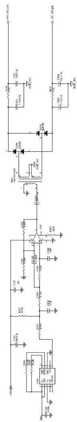
text_image
+24V 30V C791 541.26 E901 81.94 C729 .10 ICM2 2.0kV C130V F20P C200 2.0kV C200 1.0kV T821 transistor+2 DSB 35V98 ICM2 2.0kV GND-SC E029 EA099 C801 1.11.15 R311 1.20 C904 1.51.015 GVD-SC -12V 150 μΩ +24V 30V C791 541.26 E901 81.94 C729 .10 ICM2 2.0kV C130V F20P C200 2.0kV C200 1.0kV T821 transistor+2 DSB 35V88 ICM2 2.0kV GND-SC E029 EA099 C801 1.11.15 R311 1.20 C904 1.51.015 GVD-SC| IE | |
| Location Amplifier: Front Plate & Power Supply | |
| Source: Current Nomenclator | |
| Curtosis: SN/401°C | |
| DOL: 20001 | 3 or 3 |