
TL-M5200 - Screen SHARP - Free user manual and instructions
Find the device manual for free TL-M5200 SHARP in PDF.

| Product Type | 52-inch LCD Monitor |
| Model | TL-M5200 |
| Display Technology | ASV low-reflection black TFT LCD |
| Screen Size (Diagonal) | 52 1/32 inches (1322 mm) |
| Active Display Area (W x H) | 45 23/64 x 25 33/64 inches (1152 x 648 mm) |
| Resolution (Pixels) | 1920 x 1080 (2,073,600 pixels) |
| Pixel Pitch | 0.600 mm (H) x 0.600 mm (V) |
| Brightness (Typical) | 450 cd/m² |
| Maximum Colors | 16.77 million colors (8 bits/color) |
| Viewing Angle (Contrast ≥10) | 176° horizontal, 176° vertical |
| Built-in Speakers | 15 W + 15 W (4 Ω) |
| Input Terminals | HDMI, DVI-D (HDCP), RGB (mini D-sub 15-pin), 5BNC (RGB/Component), S-Video, Composite video, Audio (3.5mm) |
| Output Terminals | Monitor out (15-pin), Audio out (3.5mm), Speaker out (push terminal), LAN (RJ-45), RS-232C (D-sub 9-pin) |
| OSD Languages | English, French, Spanish, Italian, German, Dutch, Japanese |
| Power Requirements | AC 100-240 V, 50/60 Hz |
| Power Consumption (Max) | 312 W (3.2 A) |
| Standby Power Consumption | 33 W (Mode1), 1.4 W (Mode2), 0.3 W (Mode3) at AC 120 V |
| Dimensions (W x H x D, Without Stand) | 48 61/64 x 28 43/64 x 3 63/64 inches (1243 x 728 x 101 mm) |
| Weight (Without Stand) | 61.8 lbs (28.0 kg) |
| Operating Temperature | 32°F to 104°F (0°C to 40°C) |
| Operating Humidity | 30% to 80% (no condensation) |
| Backlight Life (Approx.) | 60,000 hours (at standard brightness) |
| Wall Mount Compatible | Yes, using optional AN-52AG4 bracket |
| Supplied Accessories | Power cord (1.8 m), Remote control, Batteries (AA x2), CD-ROM, Setup stand, Cable clamp, Power cord clamp, Operation manual |
| Maintenance & Cleaning | Use soft dry cloth; for stubborn dirt, use soft damp cloth; avoid liquid or aerosol cleaners |
Frequently Asked Questions - TL-M5200 SHARP
User questions about TL-M5200 SHARP
0 question about this device. Answer the ones you know or ask your own.
Ask a new question about this device
Download the instructions for your Screen in PDF format for free! Find your manual TL-M5200 - SHARP and take your electronic device back in hand. On this page are published all the documents necessary for the use of your device. TL-M5200 by SHARP.
USER MANUAL TL-M5200 SHARP
natural_image
Exterior view of a modern flat-screen TV with a black frame and 'SHARP' logo on the front panel (no additional text or symbols)IMPORTANT
- For your assistance in reporting the loss or theft of your monitor, please record the Model and Serial Number located on the rear of the monitor and retain this information.
- Before recycling the packaging, please ensure that you have checked the contents of the carton thoroughly against the list of “Supplied accessories” on page 9.
Model No.:
Serial No.:
The supplied CD-ROM contains operation instructions in English, French and Spanish. Carefully read through the operation instructions before operating the monitor.
Thank you for your purchase of a SHARP LCD Monitor. To ensure safety and many years of trouble-free operation of your product, please read "IMPORTANT INFORMATION" and "IMPORTANT SAFETY INSTRUCTIONS" carefully before using this product.
IMPORTANT INFORMATION
WARNING:
TO REDUCE THE RISK OF FIRE OR ELECTRIC SHOCK, DO NOT EXPOSE THIS PRODUCT TO RAIN OR MOISTURE.

CAUTION
RISK OF ELECTRIC SHOCK DO NOT OPEN

CAUTION: TO REDUCE THE RISK OF ELECTRIC SHOCK, DO NOT REMOVE COVER (OR BACK). NO USER-SERVICEABLE PARTS INSIDE. REFER SERVICING TO QUALIFIED SERVICE PERSONNEL.

The lightning flash with arrowhead symbol, within an equilateral triangle, is intended to alert the user to the presence of uninsulated “dangerous voltage” within the product’s enclosure that may be of sufficient magnitude to constitute a risk of electric shock to persons.

The exclamation point within a triangle is intended to alert the user to the presence of important operating and maintenance (servicing) instructions in the literature accompanying the product.
WARNING: FCC Regulations state that any unauthorized changes or modifications to this equipment not expressly approved by the manufacturer could void the user's authority to operate this equipment.
CAUTION: This product satisfies FCC regulations when shielded cables and connectors are used to connect the unit to other equipment. To prevent electromagnetic interference with electric appliances such as video equipments, use shielded cables and connectors for connections.
INFORMATION:
This equipment has been tested and found to comply with the limits for a Class B digital device, pursuant to Part 15 of the FCC Rules. These limits are designed to provide reasonable protection against harmful interference in a residential installation. This equipment generates, uses and can radiate radio frequency energy and, if not installed and used in accordance with the instructions, may cause harmful interference to radio communications. However, there is no guarantee that interference will not occur in a particular installation. If this equipment does cause harmful interference to radio or television reception, which can be determined by turning the equipment off and on, the user is encouraged to try to correct the interference by one or more of the following measures:
- Reorient or relocate the receiving antenna.
- Increase the separation between the equipment and receiver.
- Connect the equipment into an outlet on a circuit different from that to which the receiver is connected.
- Consult the dealer or an experienced radio/TV technician for help.
DECLARATION OF CONFORMITY:
SHARP LCD MONITOR, MODEL TL-M5200/TL-M4600
This device complies with Part 15 of the FCC Rules. Operation is subject to the following two conditions:
(1) This device may not cause harmful interference, and (2) this device must accept any interference received, including interference that may cause undesired operation.
RESPONSIBLE PARTY:
SHARP ELECTRONICS CORPORATION
Sharp Plaza, Mahwah, New Jersey 07495-1163
TEL: 1-800-BE-SHARP
For Business Customers: URL http://www.sharpusa.com
This product utilizes tin-lead solder, and fluorescent lamp containing a small amount of mercury. Disposal of these materials may be regulated due to environmental considerations. For disposal or recycling information, please contact your local authorities, the Electronic Industries Alliance: www.eiae.org, the lamp recycling organization: www.lamprecycle.org or Sharp at 1-800-BE-SHARP
Trademarks
- Microsoft® and Windows® are registered trademarks of Microsoft Corporation.
- “HDMI, the HDMI logo and High-Definition Multimedia Interface are trademarks or registered trademarks of HDMI Licensing LLC.”
- All other brand and product names are trademarks or registered trademarks of their respective holders.
Electricity is used to perform many useful functions, but it can also cause personal injuries and property damage if improperly handled. This product has been engineered and manufactured with the highest priority on safety. However, improper use can result in electric shock and/or fire. In order to prevent potential danger, please observe the following instructions when installing, operating and cleaning the product. To ensure your safety and prolong the service life of your LCD Monitor, please read the following precautions carefully before using the product.
1) Read these instructions.
2) Keep these instructions.
3) Heed all warnings.
4) Follow all instructions.
5) Do not use this apparatus near water.
6) Clean only with dry cloth.
7) Do not block any ventilation openings. Install in accordance with the manufacturer's instructions.
8) Do not install near any heat sources such as radiators, heat registers, stoves, or other apparatus (including amplifiers) that produce heat.
9) Do not defeat the safety purpose of the polarized or grounding-type plug. A polarized plug has two blades with one wider than the other. A grounding type plug has two blades and a third grounding prong. The wide blade or the third prong are provided for your safety. If the provided plug does not fit into your outlet, consult an electrician for replacement of the obsolete outlet.
10) Protect the power cord from being walked on or pinched particularly at plugs, convenience receptacles, and the point where they exit from the apparatus.
11) Only use attachments/accessories specified by the manufacturer.
12) Use only with the cart, stand, tripod, bracket, or table specified by the manufacturer, or sold with the apparatus. When a cart is used, use caution when moving the cart/apparatus combination to avoid injury from tip-over.
13) Unplug this apparatus during lightning storms or when unused for long periods of time.
14) Refer all servicing to qualified service personnel. Servicing is required when the apparatus has been damaged in any way, such as power-supply cord or plug is damaged, liquid has been spilled or objects have fallen into the apparatus, the apparatus has been exposed to rain or moisture, does not operate normally, or has been dropped.

Additional Safety Information
15) Power Sources — This product should be operated only from the type of power source indicated on the marking label. If you are not sure of the type of power supply to your home, consult your product dealer or local power company. For products intended to operate from battery power, or other sources, refer to the operating instructions.
16) Overloading — Do not overload wall outlets, extension cords, or integral convenience receptacles as this can result in a risk of fire or electric shock.
17) Object and Liquid Entry — Never push objects of any kind into this product through openings as they may touch dangerous voltage points or short-out parts that could result in a fire or electric shock. Never spill liquid of any kind on the product.
18) Damage Requiring Service — Unplug this product from the wall outlet and refer servicing to qualified service personnel under the following conditions:
a) When the power cord or plug is damaged,
b) If liquid has been spilled, or objects have fallen into the product,
c) If the product has been exposed to rain or water,
d) If the product does not operate normally by following the operating instructions.
Adjust only those controls that are covered by the operating instructions as an improper adjustment of other controls may result in damage and will often require extensive work by a qualified technician to restore the product to its normal operation,
e) If the product has been dropped or damaged in any way, and
f) When the product exhibits a distinct change in performance - this indicates a need for service.
19) Replacement Parts — When replacement parts are required, be sure the service technician has used replacement parts specified by the manufacturer or have the same characteristics as the original part. Unauthorized substitutions may result in fire, electric shock, or other hazards.
20) Safety Check — Upon completion of any service or repairs to this product, ask the service technician to perform safety checks to determine that the product is in proper operating condition.
21) Wall mounting — When mounting the product on a wall, be sure to install the product according to the method recommended by the manufacturer.
22) The LCD panel used in this product is made of glass. Therefore, it can break when the product is dropped or applied with impact. Be careful not to be injured by broken glass pieces in case the LCD panel breaks.
- Water and Moisture — Do not use this product near water - for example, near a bath tub, wash bowl, kitchen sink, or laundry tub; in a wet basement; or near a swimming pool; and the like.
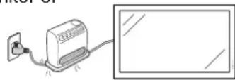
natural_image
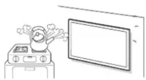
Simple line drawing of a kitchen appliance next to a monitor (no text or symbols)- Stand — Do not place the product on an unstable cart, stand, tripod or table. Placing the product on an unstable base can cause the product to fall, resulting in serious personal injuries as well as damage to the product. Use a cart, stand, tripod, bracket or table recommended by the manufacturer or sold with the product. Do not allow the monitor to receive strong shocks or to strongly vibrate. When mounting the product on a wall, be sure to follow the manufacturer's instructions. Use only the mounting hardware recommended by the manufacturer.
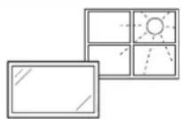
- Selecting the location — Select a place with no direct sunlight and good ventilation.
- Ventilation — The vents and other openings in the cabinet are designed for ventilation. Do not cover or block these vents and openings since insufficient ventilation can cause overheating and/or shorten the life of the product. Do not place the product on a bed, sofa, rug or other similar surface, since they can block ventilation openings. This product is not designed for built-in installation; do not place the product in an enclosed place such as a bookcase or rack, unless proper ventilation is provided or the manufacturer's instructions are followed.
- The Liquid Crystal panel used in this product is made of glass. Therefore, it can break when the product is dropped or applied with impact. Be careful not to be injured by broken glass pieces in case the panel breaks.

- Heat — The product should be situated away from heat sources such as radiators, heat registers, stoves, or other products (including amplifiers) that produce heat.
- The Liquid Crystal panel is a very high technology product with 2,073,600 pixels, giving you fine picture details. Occasionally, a few non-active pixels may appear on the screen as a fixed point of blue, green or red. Also, if the screen is viewed from an acute angle there may be uneven colors or brightness. Please note that this does not affect the performance of your product.
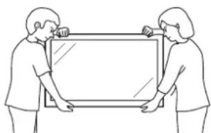
Precautions when transporting the monitor
- Be sure to always carry the monitor by two people holding it with two hands — one hand on each side of the monitor.
- Do not hold onto the attached optional speakers when transporting the monitor.
natural_image
Line drawing of two people holding a large rectangular frame (no text or symbols)- Lightning — For added protection for this monitor equipment during a lightning storm, or when it is left unattended and unused for long periods of time, unplug it from the wall outlet. This will prevent damage to the equipment due to lightning and power-line surges.
natural_image
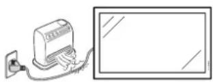
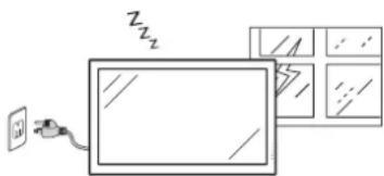
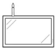
Simple line drawing of a wall-mounted device with a plug and cable, next to a grid of windows (no text or symbols)- To prevent fire, never place any type of candle or flames on the top or near the monitor.
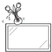
- To prevent fire or shock hazard, do not expose this product to dripping or splashing. No objects filled with liquids, such as vases, should be placed on the product.
- To prevent fire or shock hazard, do not place the power cord under the monitor or other heavy items.
- Turn off the power and unplug the power cord from the wall outlet before handling.
- Use a soft cloth and gently wipe the surface of the display panel. Using a hard cloth may scratch the panel surface.
- Use a soft damp cloth to gently wipe the panel when it is really dirty. (It may scratch the panel surface when wiped strongly.)
- If the panel is dusty, use an anti-static brush, which is commercially available, to clean it.
- To protect the panel, do not use a dirty cloth, liquid cleaners or chemical cloth to clean it, such materials may damage the panel surface.
- To clean the outer cabinet, use the same method. Do not use liquid or aerosol cleaners.
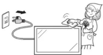
natural_image
Illustration of a person using an electric plug to interact with a screen (no text or symbols present)- Do not display a still picture for a long time, as this could cause an afterimage to remain.
- Never rub or tap the monitor with hard objects.
- Please understand that SHARP CORPORATION bears no responsibility for errors made during use by the customer or a third party, nor for any other malfunctions or damage to this product arising during use, except where indemnity liability is recognized under law.
- This monitor and its accessories may be upgraded without advance notice.
- Do not use the monitor where there is a lot of dust, where humidity is high, or where the monitor may come into contact with oil or steam, as this could lead to fire.
- Ensure that no objects such as paper clips or pins enter the monitor as this could lead to fire or electric shock.
Fluorescent Tubes
- The fluorescent tubes in this product have a limited lifetime.
* If the screen gets dark, flashes, or does not turn on, change the fluorescent tubes with new exclusive ones.
* For more information, please contact your product dealer.
- Because of the property of fluorescent tubes, the screen may flash during the initial period of use. If this happens, please turn off the power of the monitor and turn on again to confirm operation.
Contents
Introduction
DEAR SHARP CUSTOMER .... 1
IMPORTANT INFORMATION .... 1
Trademarks 2
IMPORTANT SAFETY INSTRUCTIONS ..... 3
How to Access the PDF Operation
Manuals 8
SETUP MANUAL 8
Accessories 9
Part Names 10
Preparation
How to Install the Monitor 13
Mounting precautions 13
Attaching the setup stand 13
Mounting the monitor on the wall 14
Connecting Peripheral Equipment ..... 16
Connecting external speakers 19
Connecting multiple monitors 19
Controlling the monitor by a computer..... 20
Connecting the Power Cord 21
Binding Cables 21
Preparing the Remote Control 22
Installing the batteries 22
Remote control operation range 22
Operation
Turning the Monitor On/Off 23
Turning on the power 23
Turning off the power 23
Operating with the Remote Control ..... 24
Switching the input mode 24
Adjusting the volume 24
Displaying the black screen and turning off the sound temporarily 24
Resize mode 25
Auto Sync adjustment (Auto Sync) ...... 27
Freezing a moving image 27
Selecting AV mode 27
Displaying an enlarged portion of an image 27
Split-screen viewing 28
Using the remote control as the wireless computer mouse 29
Menu Operations 30
Basic menu operations 30
List of menu items 31
Picture menu 32
Audio menu 34
Power Control menu 34
Setup menu 35
Option menu 40
Appendix
Troubleshooting 45
For SHARP Assistance 46
Specifications 47
Index 52
How to Access the PDF Operation Manuals
PDF operation manuals in several languages are included in the CD-ROM. To utilize these manuals, you need to install Adobe ^® Reader ^® on your computer (Windows ^® or Macintosh ^® ).
Please download Adobe ^® Reader ^® from the Internet (http://www.adobe.com).
■ Accessing the PDF manuals
For Windows®:
1 Insert the CD-ROM in the CD-ROM drive.
2 Double click the "My Computer" icon.
3 Double click the "CD-ROM" drive.
4 When you want to view the operation manual
1) Double click the "MANUALS" and the "M520_460" folder.
2) Double click the language (name of the folder) that you want to view.
3) Double click the PDF file to access the operation manual.
When you want to view the SETUP MANUAL
1) Double click the "SETUP" and the "M520_460" folder.
2) Double click the language (name of the folder) that you want to view.
3) Double click the PDF file to access the SETUP MANUAL.
For Macintosh®:
1 Insert the CD-ROM in the CD-ROM drive.
2 Double click the "CD-ROM" icon.
3 When you want to view the operation manual
1) Double click the "MANUALS" and the "M520_460" folder.
2) Double click the language (name of the folder) that you want to view.
3) Double click the PDF file to access the operation manual.
When you want to view the SETUP MANUAL
1) Double click the "SETUP" and the "M520_460" folder.
2) Double click the language (name of the folder) that you want to view.
3) Double click the PDF file to access the SETUP MANUAL.

Note
- If the desired PDF file cannot be opened by double clicking the mouse, start Adobe ^ Reader ^ first, then specify the desired file using the "File", "Open" menu.
SETUP MANUAL
Refer to the "SETUP MANUAL" contained on the supplied CD-ROM for details.
RS-232C Specifications and Commands 2
Setting up the Monitor Network Environment .... 10
Controlling the Monitor via LAN 16
Setting up the Monitor Using RS-232C or Telnet ...... 21
Multi Screen 31
Troubleshooting 39
Accessories
■ Supplied accessories
If any component should be missing, please contact your dealer.
□ Liquid Crystal Display: 1
natural_image
Empty white rectangle with black border, no text or symbols present□ Power cord (Approx. 6 feet [1.8 m]): 1
☐ R-6 battery ("AA" size, UM/SUM-3, HP-7 or similar): 2
□ CD-ROM: 1
☐ Operation manual: 1
□ Remote control: 1
natural_image
Line drawing of a remote control with multiple buttons (no text or symbols)□ Setup stand: 1

natural_image
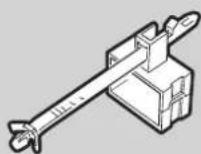
Collection of mechanical components and connectors (no text or symbols visible)□ Cable clamp: 1
□ Power cord clamp: 1
* For environmental protection!
Do not dispose of batteries in household waste. Follow the disposal instructions for your area.

Note
- Codes in "<>" are Replacement parts codes.
■ Optional accessories
The listed optional accessories are available for the LCD Monitor.
Please contact the nearest Sharp Authorized Dealer.
☐ Speaker unit : AN-52SP2, AN-46SP2
□ Wall-mount bracket : AN-52AG4
□ USB remote receiver : AN-MR2

Note
- Some of the optional accessories may not be available depending on the region. Please check with your nearest Sharp Authorized Dealer or Service Center.
- Additional optional accessories may be available in the near future. When purchasing, please read the newest catalog for compatibility and check the availability.
Part Names
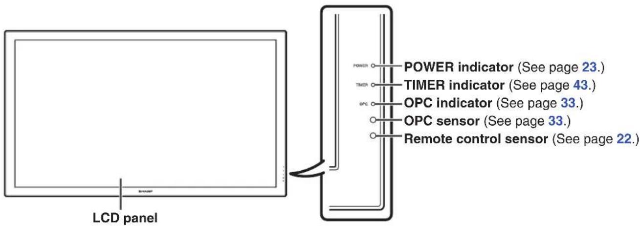
Front view
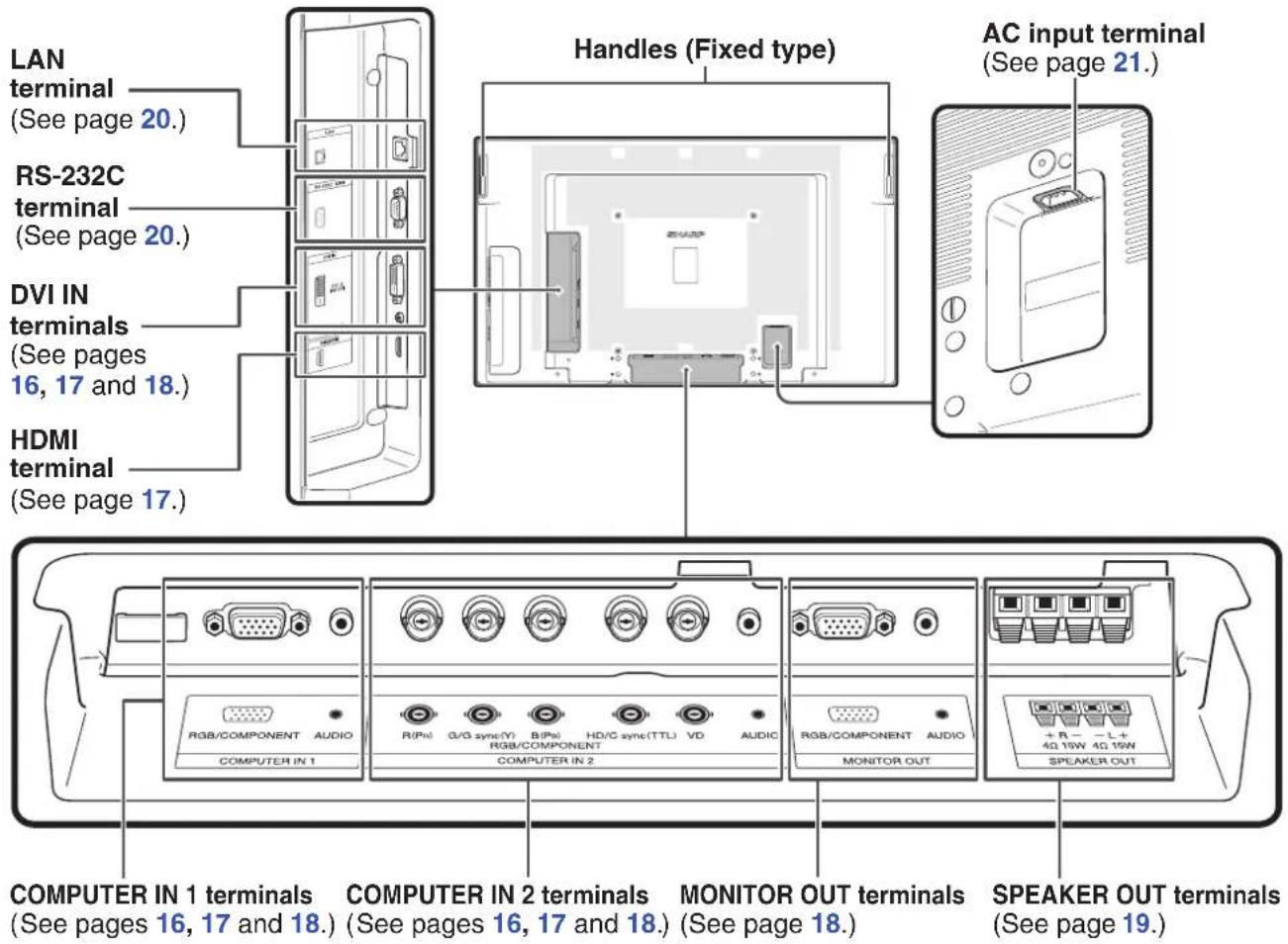
Rear view

Note
- The illustrations in this operation manual are for explanation purposes and may vary slightly from the actual operations.
- The illustrations used throughout this manual are based on TL-M5200.
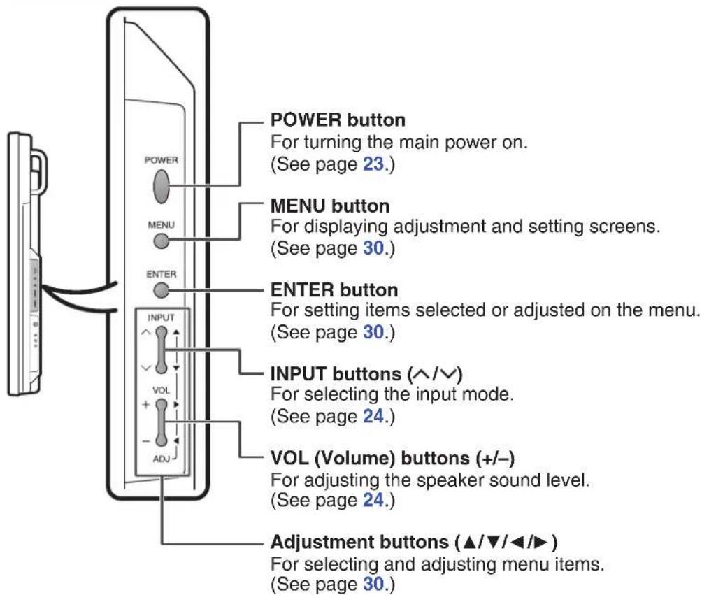
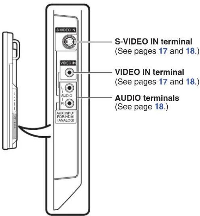
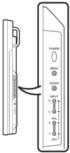
Side view
Remote control
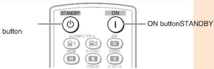
STANDBY button
For putting the monitor into the standby mode.
(See page 23.)
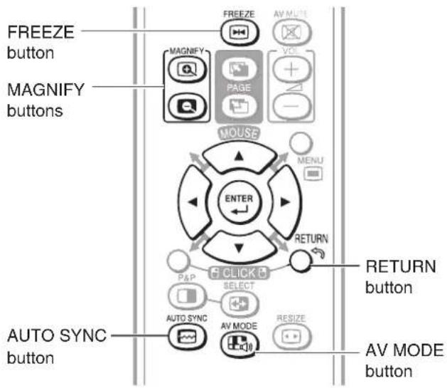
FREEZE button
For freezing images.
(See page 27.)
MAGNIFY buttons
For enlarging/reducing part of the image.
(See page 27.)
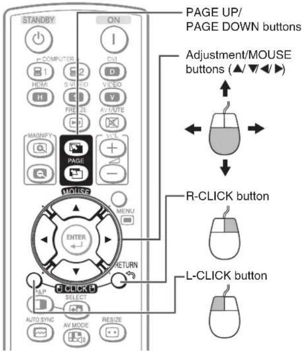
PAGE UP/PAGE DOWN buttons
Functions the same as the [Page Up] and [Page Down] keys on a computer keyboard using the optional USB remote receiver when the monitor is connected to a computer.
(See page 29.)
Adjustment/MOUSE buttons (▲/▼/◄/►)
- For selecting and adjusting menu items.
(See page 30.) - The computer cursor may be moved using the optional USB remote receiver when the monitor is connected to a computer. (See page 29.)
L-CLICK button
The Left button can be clicked using the optional USB remote receiver when the monitor is connected to a computer.
(See page 29.)
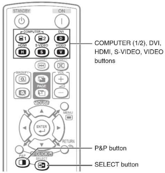
P&P button
For setting the split-screen picture mode. Press P&P again to return to normal view.
(See page 28.)
AUTO SYNC button
For automatically adjusting images when connected to a computer.
(See page 27.)
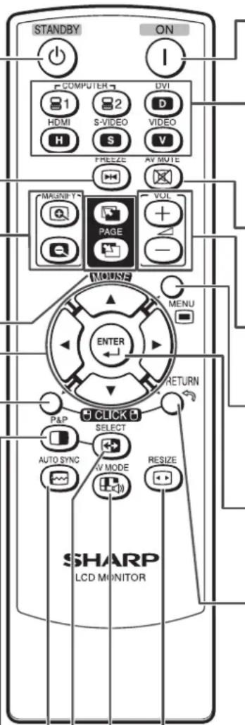
ON button
For turning the power on.
(See page 23.)
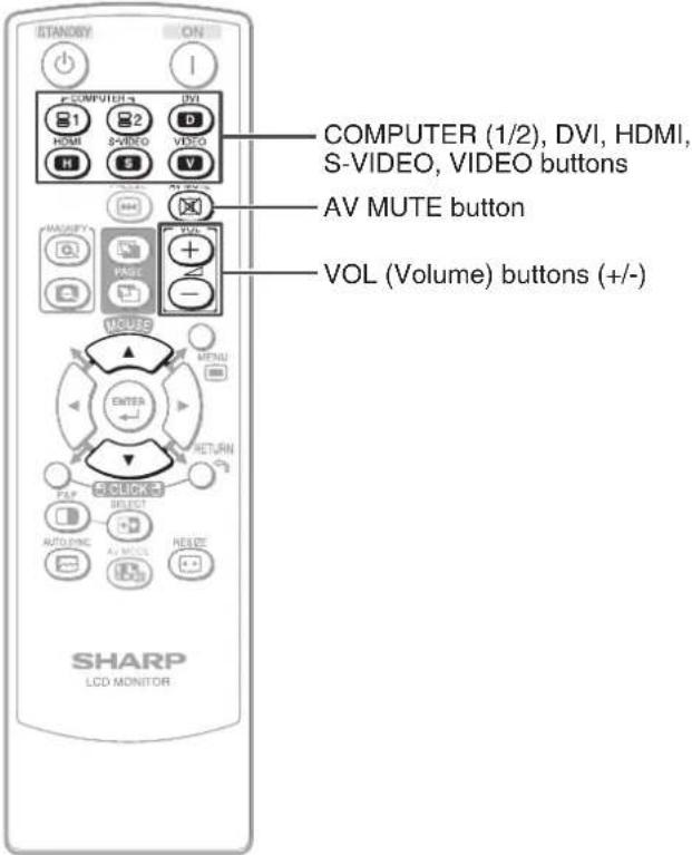
COMPUTER 1, COMPUTER 2, DVI, HDMI, S-VIDEO, VIDEO buttons
For switching to the respective input modes.
(See page 24.)
AV MUTE button
For temporarily displaying a black screen and turning off the sound.
(See page 24.)
VOL (Volume) buttons (+/-)
For adjusting the speaker sound level.
(See page 24.)
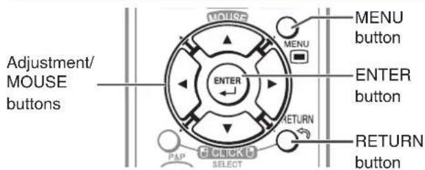
MENU button
For displaying adjustment and setting screens.
(See page 30.)
ENTER button
For setting items selected or adjusted on the menu.
(See page 30.)
RETURN/R-CLICK button
- For returning to the previous menu screen during menu operations.
(See page 30.)
- The Right button can be clicked using the optional USB remote receiver when the monitor is connected to a computer.
(See page 29.)
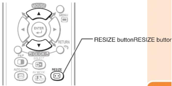
RESIZE button
For switching the picture size.
(See page 25.)
AV MODE button
For selecting appropriate settings for picture and audio.
(See page 27.)
SELECT button
For selecting either screen to be active in split-screen mode.
(See page 28.)
How to Install the Monitor
Mounting precautions
- Mounting the monitor on the wall requires special expertise and the work must be performed by an authorized SHARP dealer. You should never attempt to perform any of this work yourself. Our company will bear no responsibility for accidents or injuries caused by improper mounting or mishandling.
- This monitor is designed to be installed on a concrete wall or pillar. Reinforced work might be necessary for some materials such as plaster / thin plastic board / wood before starting installation.
This monitor and bracket must be installed on a wall which can endure at least 4 times or more the weight of the monitor. Install by the most suitable method for the material and the structure.
• This monitor can not be installed in a vertical orientation. - Since the monitor is heavy, consult your dealer before installing, removing or moving the monitor.
- When installing, removing or moving the monitor, ensure that this is carried out by at least 2 people.
- When moving the monitor, be sure to hold it with the handles both on the rear and the unit bottom. Do not hold the LCD panel. This may cause product damage, failure, or injury.
- This monitor should be used at an ambient temperature between 32^ (0^) and 104^ (40^) . Provide enough space around the monitor to prevent heat from accumulating inside.
- Do not block any ventilation openings. If the temperature inside the monitor rises, this could lead to a malfunction.
- Do not place the monitor on a device which generates heat.
Attaching the setup stand
Before performing work spread cushioning over the base area to lay the monitor on. This will prevent it from being damaged.
!Caution
- Please note that the setup stand is for temporary use only until the monitor is properly mounted.
- Attach the stand in the correct direction.
- Be sure to follow the instructions. Incorrect installation of the stand may result in the monitor falling over.
1

natural_image
Illustration of various screw and cylindrical components with different mounting styles (no text or symbols)Confirm that there are 10 screws and 6 caps supplied with the stand.
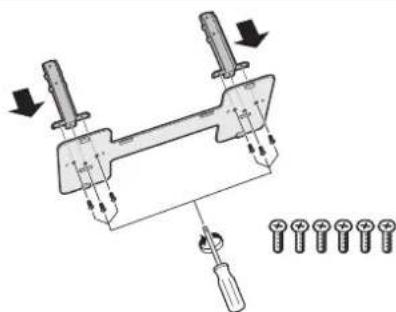
2
natural_image
Mechanical assembly diagram showing a clamp mechanism with screws and bolts, no text or symbols presentAssemble the stand using the 6 screws.
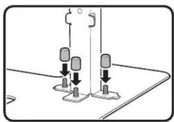
3
natural_image
Diagram of a sewing machine needle with two base stations and a vertical support (no text or symbols)Put the caps on the screws that have been screwed into the stand.
4
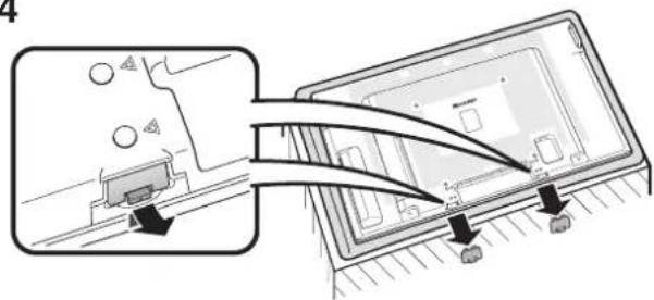
Remove the protective covers from the underside of the monitor.
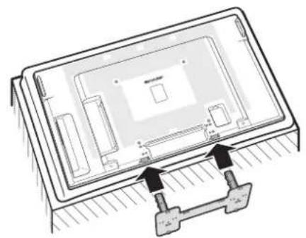
5
natural_image
Technical line drawing of a device with internal components and mounting bracket (no text or symbols)Insert the stand into the openings on the underside of the monitor.
6
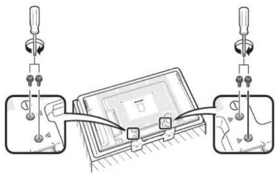
Insert and tighten the screws into the 4 holes on the rear of the monitor.

Note
- To detach the stand, perform the steps in reverse order.
- Store the protective covers. You will need them after detaching the stand.
Mounting the monitor on the wall
■ Handling and precautions with the wall-mounted monitor
- You can mount the monitor on the wall using the optional AN-52AG4 bracket.
- For details, refer to the instructions supplied with the optional AN-52AG4 bracket.
!Caution
- This monitor should be mounted on the wall only with the AN-52AG4 (SHARP) wall-mount bracket. The use of other wall-mount brackets may result in an unstable installation and may cause serious injuries.
- Installing the monitor requires special skill that should only be performed by qualified service personnel. Customers should not attempt to do the work themselves. SHARP bears no responsibility for improper mounting or mounting that results in accident or injury.
Using a SHARP recommended bracket to mount the monitor
- You can ask a qualified service professional about using a SHARP recommended AN-52AG4 bracket to mount the monitor to the wall.
- Carefully read the instructions that come with the bracket before beginning work.
Hanging on the wall
AN-52AG4 wall-mount bracket. (See the bracket instructions for details.)
About setting the monitor angle
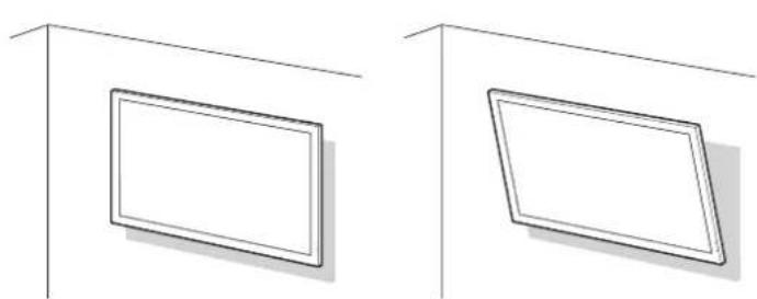
natural_image
Two identical line drawings of a rectangular frame with shading, placed on a plain background (no text or symbols)Vertical mounting Angular mounting
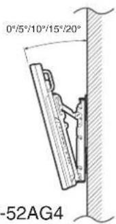
- The center of the display TL-M5200: 5¼ inch (136 mm) under the "A" position.
TL-M4600: 6 ^55 / _64 inch (174 mm) under the "A" position.
• Refer to the operation manual of AN-52AG4 for details.
■ Mounting the monitor on the wall
Attach the monitor to the wall-mount brackets according to the procedure below.
1
Unfasten the 4 screws used to secure the stand in place.
2
Use the protective cover to prevent dust from entering the underside of monitor where the stand has been detached.
3
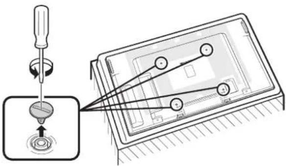
Detach the 4 caps at the 4 locations on the rear of the monitor.
4
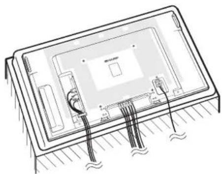
natural_image
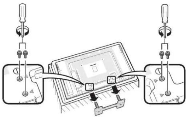
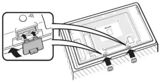
Technical line drawing of a rectangular electronic device with internal components and wiring (no text or symbols)Connect and bind the power cord and terminal cables.
5
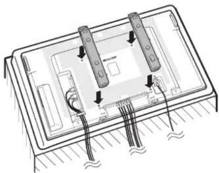
natural_image
Diagram of a device with two controllers and wiring, no visible text or symbolsAttach the wall-mount brackets (L/R).
6
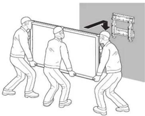
natural_image
Illustration of three workers carrying a large whiteboard with a wall-mounted device, no text or symbols presentSet the monitor on the wall.
Connecting Peripheral Equipment
!Caution
- Be sure to turn off the power and disconnect the plug from the power outlet before connecting/disconnecting cables. Also, read the manual of the equipment to be connected.
- Be careful not to mix up the input terminal with the output terminal when connecting cables. Mixing up the input and output terminals may cause malfunctions and other problems.
- After making all connections, turn on the monitor and then the other pieces of equipment. When connecting a computer, ensure that it is the last equipment to be turned on after all the connections are made.
- You may need other cables or connectors not listed below.
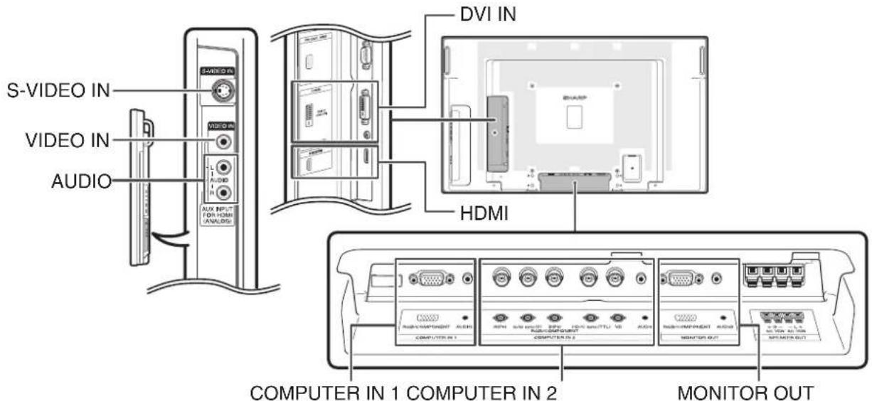
| Equipment | Terminal on connected equipment | Cable (commercially available) | Terminal on the monitor |
Computer RGB output terminal  | 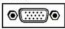 | RGB cable COMPUTER IN 1 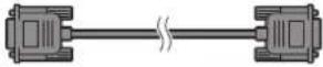 | 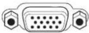 |
RGB output terminal 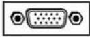 | 5 BNC to 15-pin D-sub cable COMPUTER IN 2 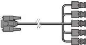 | ||
DVI digital output terminal 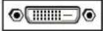 | DVI Digital cable DVI IN 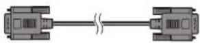 | [DVI-D (HDCP)] |

Note
- Images may not be displayed properly depending on the computer (graphics board) to be connected.
- See page 49 "Computer compatibility chart" for a list of computer signals compatible with the monitor. Use with computer signals other than those listed may cause some of the functions to not work.
- A Macintosh adaptor may be required for use with some Macintosh computers. Contact your nearest Macintosh Dealer.
- Depending on the computer you are using, an image may not be displayed unless the computer's external output port is switched on (e.g. Press "Fn" and "F5" keys simultaneously when using a SHARP notebook computer). Refer to the specific instructions in your computer's operation manual to enable your computer's external output port.
| Equipment | Terminal on connected equipment | Cable (commercially available) | Terminal on the monitor |
Video equipment DVI    | digital output terminal | DVI Digital cable DVI IN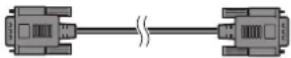 | DVI-D 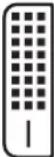 (HDCP) (HDCP) |
Component video output terminal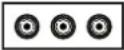 | 3 RCA to mini D-sub 15 pin cable COM 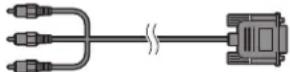 | PUTER IN 1 | |
S-video output terminal | S-video cable S-VIDEO IN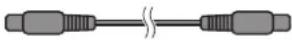 |  | |
Video output terminal | Video cable VIDEO IN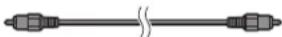 |  | |
HDMI output terminal | HDMI cable HDMI |  | |
| RGB output terminal | 5 RCA RGB cableBNC to RCA adaptors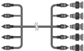 | COMPUTER IN 2 | |
| Component video output terminal | BNC to RCA adaptorsComponent video cable |

Note
- Depending on specifications of video equipment or HDMI to DVI digital cable, the signal transmission may not work properly. (The HDMI specification does not support all connections to video equipment that has HDMI digital output terminal using HDMI to DVI digital cable.)
- For details on compatibility for connection, see support information on DVI connection provided by the video equipment manufacturer.
- When you connect video equipment with a 21-pin RGB output (Euro-scart) to the monitor, use a commercially available cable that fits in the monitor terminal you want to connect.
- The monitor does not support RGBC signals via the Euro-scart.
Connecting Peripheral Equipment
| Equipment | Terminal on connected equipment | Cable (commercially available) | Terminal on the monitor |
Camera/Video game  | Component video output terminal | Cables for a camera or a video game/3 RCA to mini D-sub 15 pin cable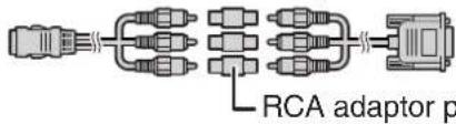 lug lug | COMPUTER IN 1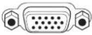 |
| S-video output terminal | Cables for a camera or a video game S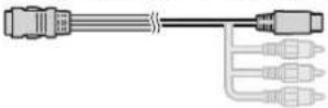 | VIDEO IN | |
| Video output terminal | Cables for a camera or a video game V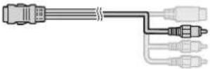 | DEO IN | |
Audio equipment ø3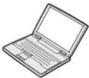 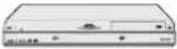   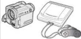 | 5 mm audio output terminal | ø3.5 mm stereo or mono audio cable A | AUDIO (for DVI IN)AUDIO (for COMPUTER IN 1)(for COMPUTER IN 2)[for S-VIDEO IN](for VIDEO IN)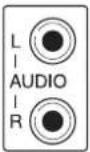 |
RCA audio output terminal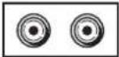 | RCA audio cable AUDIO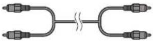 | ||
| Audio output terminal | Cables for a camera or a video game | ||
Monitor RGB input | terminal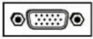 | RGB cable MONITOR OUT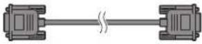 | 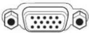 |
Amplifier ø3.5 mm audio input terminal | audio input terminal | ø3.5 mm stereo or mono audio cable AUDIO(tor MONITOR OUT)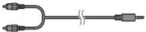 | AUDIO(for MONITOR OUT)[●] |
| RCA audio input terminal |

Note
- When using the 3.5mm mono audio cable, the volume level will be half of when using the 3.5mm stereo audio cable.
MONITOR OUT terminals
- Audio and images from equipment connected to the COMPUTER IN 1 or COMPUTER IN 2 terminals can be output from the MONITOR OUT terminals.
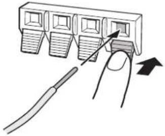
Connecting external speakers
Be sure to use external speakers with an impedance of 4 Ω and a rated input of at least 15 W.
1 While pushing the tab, insert the tip of the cable.
natural_image
Diagram showing a finger pressing down on a multi-pin connector with an arrow indicating force (no text or symbols present)2 Release the tab.

Note
- Be sure to connect the + and - terminals and the left and right speakers properly.
- Avoid short circuiting the + and - terminals.
- It is recommended that you use the optional Sharp speaker unit (AN-52SP2/AN-46SP2) for external speakers.
Connecting multiple monitors
You can connect multiple monitors by using the RGB/COMPONENT input terminals (COMPUTER IN 1 or COMPUTER IN 2) and the RGB/COMPONENT output terminals (MONITOR OUT).

Note
- The length of the signal cables or surrounding environment may affect the image quality.
- When connecting multiple monitors, the screen may not display properly. In this case, turn off the power to all the monitors connected and then turn the power on again.
- For details, refer to the "SETUP MANUAL".
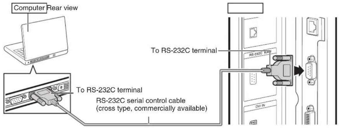
Controlling the monitor by a computer
When the RS-232C terminal on the monitor is connected to the RS-232C serial terminal on the computer, or when the LAN terminal on the monitor is connected to the LAN terminal on the computer, the computer can be used to control the monitor. Refer to the "SETUP MANUAL" contained on the supplied CD-ROM for details.
■ When connecting to a computer using an RS-232C serial control cable

Note
- The RS-232C function may not operate if your computer terminal is not correctly set up. Refer to the operation manual of the computer for details.
- Refer to "SETUP MANUAL" contained on the supplied CD-ROM for the RS-232C specifications and commands.
- Do not connect the RS-232C cable to a terminal other than the RS-232C terminal on the computer. This may damage your computer or monitor.
- Do not connect or disconnect an RS-232C serial control cable to or from the computer while it is on. This may damage your computer.
■ When connecting to the LAN terminal using a LAN cable
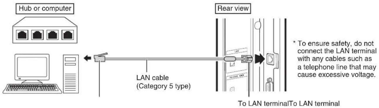

Note
- When connecting to a hub, use straight-through Category 5 (CAT.5) type cable.
- When connecting to a computer, use cross-over Category 5 (CAT.5) type cable.
Connecting the Power Cord
!Caution
- Do not use a power cord other than the one supplied with the monitor.

Be sure to use a power outlet of AC 120 V (60 Hz).
Using power supply other than the one specified may cause fire.
- Place the monitor close to the AC outlet, and keep the power plug within reach.
- This product must only be connected to an AC 120 V, 60 Hz, grounded (3-prong) outlet. Connecting it to any other kind of outlet will damage the product and invalidate the warranty.
1 Plug the power cord (supplied) into the AC input terminal.
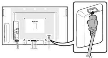
2 Plug the power cord (supplied) into the AC power outlet.
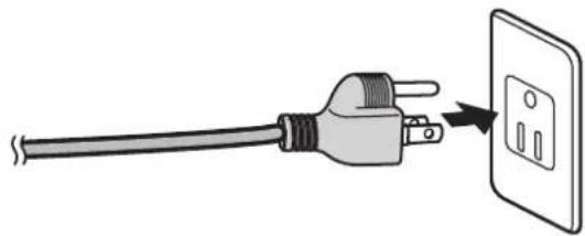
natural_image
Illustration of a plug being inserted into an electrical outlet (no text or symbols)Binding Cables
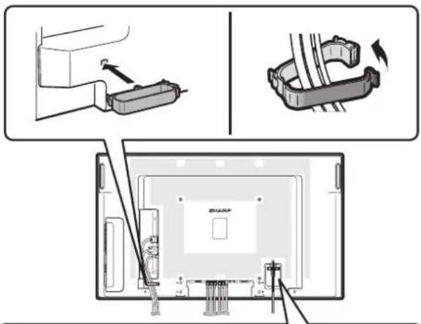

■ Attaching the cable clamp
The cables connected to the terminals on the back of the monitor can be neatly bundled using the supplied cable clamp as shown in the illustration.

Note
- A cable clamp cannot be easily removed once it is attached.
■ Fastening the power cord
The power cord can be fastened using the supplied power cord clamp. This will prevent the power cord from being disconnected accidentally.
1 Attach the supplied power cord clamp to the power cord, making sure the power cord clamp is circular hole-side down.
2 Insert the tip of the band into the hole for the power cord clamp.
3 While holding the tail of the band, slide the fastened part toward the AC input terminal.
Preparing the Remote Control
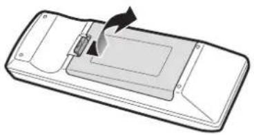
Installing the batteries
1 Pull down the tab on the cover and remove the cover towards the direction of the arrow.
2 Insert the batteries.
- Insert the batteries making sure the polarities correctly match the + and - marks inside the battery compartment.
3 Insert the lower tab of the cover into the opening, and lower the cover until it clicks in place.
natural_image
Diagram of a device with a handle and arrow indicating rotation or movement (no text or symbols)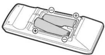
natural_image
Diagram of a mobile phone casing showing battery and charging mechanism (no text or labels)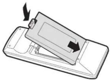
natural_image
Diagram of a device with an open lid and directional arrows indicating motion (no text or symbols)Incorrect use of the batteries may cause them to leak or explode. Please follow the precautions below.

Caution
- Danger of explosion if battery is incorrectly replaced. Replace only with alkaline or manganese batteries.
- Insert the batteries making sure the polarities correctly match the + and - marks inside the battery compartment.
- Batteries of different types have different properties, therefore do not mix batteries of different types.
- Do not mix new and old batteries.
This may shorten the life of new batteries or may cause old batteries to leak. - Remove the batteries from the remote control once they have run out, as leaving them in can cause them to leak.
Battery fluid from leaked batteries is harmful to skin, therefore ensure you wipe them first and then remove them using a cloth. - The batteries included with this monitor may run down in a short period, depending on how they are kept. Be sure to replace them as soon as possible with new batteries.
- Remove the batteries from the remote control if you will not be using the remote control for a long time.
- Comply with the rules (ordinance) of each local government when disposing of worn-out batteries.
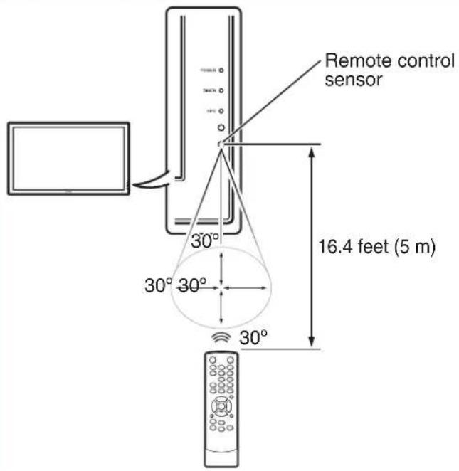
Remote control operation range
The operation range of the remote control is approx. 16.4 feet (5 m) at an angle of approx 30° from the center to the top/bottom/right/left of the remote control sensor.

Note
- Do not expose the remote control to shock by dropping or stepping on it. This could lead to a malfunction.
- Do not expose the remote control to liquids, and do not place it in an area with high humidity.
- The remote control may not work properly if the remote control sensor is under direct sunlight or strong lighting.
- Objects between the remote control and the remote control sensor may prevent proper operation.
- Replace the batteries when they run low as this may shorten the remote control's operation range.
- If a fluorescent light is illuminated near the remote control, it may interfere with proper operation.
- Do not use it with the remote control of other equipment such as air conditioner, stereo components, etc.
Turning the Monitor On/Off
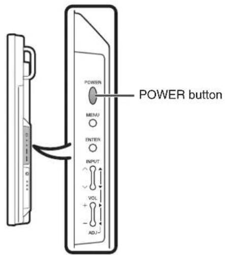
Turning on the power
Press POWER on the monitor.
• POWER indicator (Green): The monitor is on.
- After turning the power "ON" by pressing POWER on the monitor, you can turn the power ON by pressing ON on the remote control.
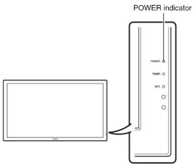
- When switching the POWER, ON or STANDBY buttons off and back on, always wait for at least 5 seconds. A short interval may result in a malfunction.
Turning off the power
Press STANDBY on the remote control.
• The monitor enters standby mode.
- The POWER indicator on the monitor changes from green to red.
Press POWER on the monitor.
• The POWER indicator on the monitor turns off.
- When the monitor is turned off by POWER on the monitor, you cannot turn on the power by pressing ON on the remote control.
POWER indicator
| Lighting (Green) | Power ON |
| Lighting (Red) Standby | |
| Lights off Power | OFF |
| Flashing (Orange) | When “Power On Delay” function is activated. |
| Flashing (Green) | Input signal standby (when “Power Management” is set to “Mode2” in the Power Control menu.) |

Note
- If you are not going to use this monitor for a long period of time, be sure to remove the power cord from the AC outlet.
- Minor power is consumed when the unit is in standby mode.
Operating with the Remote Control
Switching the input mode
Select the appropriate input mode for the connected equipment.
Press COMPUTER (1/2), DVI, HDMI, S-VIDEO or VIDEO to select the input mode.
- When you press INPUT on the monitor, the INPUT list appears.
Press ▲/▼ to switch the input mode.
Adjusting the volume
Press VOL +/- to adjust the volume.
- You can also adjust the volume using VOL +/- on the monitor.


Note
- Pressing VOL—will lower the volume.
- Pressing VOL+ will raise the volume.
- You can set the volume to different levels for each input source.
- To adjust sound via the audio output terminal (MONITOR OUT), set "Audio Output" to "VAO" in the "Option" menu. (See page 40.)
Displaying the black screen and turning off the sound temporarily
Press AV MUTE to temporarily display a black screen and turn off the sound.
AV MUTE

Note
- Pressing AV MUTE again will turn the image back on.
Resize mode
This function allows you to modify or customize the Resize mode to enhance the input image. Depending on the input signal, you can choose a desired image.
1 Press RESIZE.
- The Resize mode menu appears.
- The menu lists the Resize mode options selectable for the type of signal currently received.
Resize
Normal
Zoom 14:9
S.Stretch
Full
Cinema 16:9
Cinema 14:9
flowchart
graph TD
    A["MOUSE"] --> B["ENTER"]
    C["MENU"] --> B
    D["RETURN"] --> B
    E["PAP"] --> F["SELECT"]
    G["AUTO SYNC"] --> H["AV MODE"]
    I["RESIZE"] --> J["RESIZE buttonRESIZE button"]
2 Press RESIZE or ▲/▼ while the Resize mode menu is displayed on the screen.

Note
- You can also set the Resize mode from the "Option" menu. (See page 42.)
AV input
| Selectable items Description | ||
| Normal | 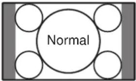 | For 4:3 “standard” pictures. A side bar appears on each side. |
| Zoom 14:9 | 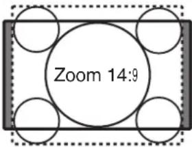 | For 14:9 letterbox pictures. A thin side bar appears on each side, and the top and bottom of the image may be cut off depending on the input signal. |
| S. Stretch |  | Only the ends of the image are stretched horizontally. |
| Full |  | For 16:9 squeeze pictures. |
Operating with the Remote Control
| Selectable items Description | ||
| Cinema 16:9 | 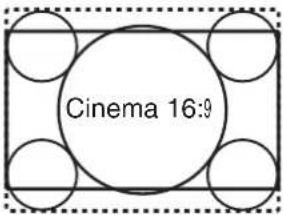 | For 16:9 letterbox pictures. The top and bottom of the image may be cut off depending on the input signal. |
| Cinema 14:9 | 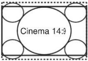 | For 14:9 letterbox pictures. The top and bottom of the image may be cut off depending on the input signal. |
| Dot by Dot Display an image with the same number of pixels on the screen (only when receiving 1080I/1080P signal via component or HDMI terminals). | ||
Computer input
| Selectable items Description | ||
| Normal | 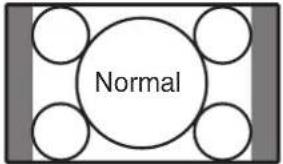 | Keeps the original aspect ratio in a full screen display. |
| Full |  | An image fully fills the screen. |
| Dot by Dot |  | Detects the resolution of the signal and displays an image with the same number of pixels on the screen.Displays an image that overlaps the screen when a signal of greater resolution than the size of the screen is input. |

Note
- When using the Resize function to select an image size with a different aspect ratio to a TV program or video image, the image will look different from its original appearance. Keep this in mind while choosing an image size.
- The use of the Resize or split-screen function to compress or stretch the image for commercial purposes/public displays in a café, hotel, etc. may be an infringement of copyright protected by law for copyright holders. Please use caution.
- While watching non-widescreen images (4:3), if you use the Resize function to fill the screen, parts of the outer edge of the image will be cut off or distorted. To watch original images as the producers intended, set the Resize mode to "Normal".
- When "Multi Screen" is set, the Resize mode is fixed to "Full".
- When split-screen display is selected, the Resize mode cannot be changed.
- When playing commercial software, parts of the image (like subtitles) may be cropped. In this case select the optimal screen size using the Resize function of this monitor. With some software, there may be noise or distortion at the edges of the screen. This is due to the characteristics of the software, and is not a malfunction.
- Depending on the original image size, black bands may remain at the edges of the screen.
flowchart
graph TD
    A["FREEZE button"] --> B["MAGNIFY button"]
    B --> C["MOVE"]
    C --> D["ENTER"]
    D --> E["PAP"]
    E --> F["AUTO SYNC button"]
    F --> G["AV MODE"]
    G --> H["RESET"]
    H --> I["AV MODE button"]
    J["RETURN button"] --> K["CLICK SELECT"]
    K --> L["MENU"]
    L --> M["MOVE"]
    style A fill:#f9f,stroke:#333
    style B fill:#ccf,stroke:#333
    style C fill:#cfc,stroke:#333
    style D fill:#fcc,stroke:#333
    style E fill:#cff,stroke:#333
    style F fill:#ffc,stroke:#333
    style G fill:#cfc,stroke:#333
    style H fill:#fcc,stroke:#333
    style I fill:#ffc,stroke:#333
Auto Sync adjustment (Auto Sync)
"Clock", "Phase", "H-Position", and "V-Position" are automatically adjusted.
Press AUTO SYNC.
- You can also perform Auto Sync adjustment from the "Setup" menu.
Freezing a moving image
1 Press FREEZE.
- The image is frozen.
2 Press FREEZE again to return to the moving image from the currently connected device.

Note
- The still image automatically goes out after 30 minutes.
Selecting AV mode
You can select the appropriate mode for the image, such as movie or video game.
Press AV MODE.
- When pressing AV MODE, the AV mode changes in the following order:
→Standard→Presentation→Movie→Game→sRGB

Note
• See page 32 for details on AV mode.
- "sRGB" is displayed only when RGB signal is input.
Displaying an enlarged portion of an image
Graphs, tables and other portions of images can be enlarged. This is helpful when providing more detailed explanations.
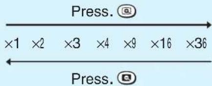
1 Press MAGNIFY.
- Enlarges the image.
- Pressing 🔒 or ⓌMAGNIFY enlarges or reduces the image.

Note
- You can change the location of the enlarged image using ▲/▼/◄/►.
2 Press RETURN to cancel the operation.
• The magnification then returns to ×1.

Note
- The selectable magnifications differ depending on the input signal.
- In the following cases, the image will return to the normal size (× 1) .
- When switching the input mode.
- When RETURN has been pressed.
- When the input signal is changed.
- When the input signal resolution and refresh rate (vertical frequency) change.
- When the Resize mode is changed.
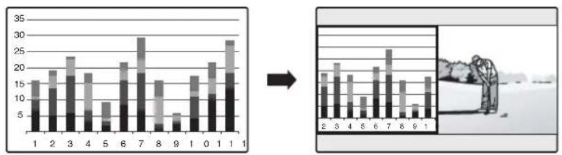
Split-screen viewing
You can display two pictures on the screen simultaneously.
1 Press P&P.
- Split-screen appears.
- The current input is moved to the left side screen display and surrounded by a blue frame.
- The other input appears on the right side screen display.
bar
| Category | Value 1 | Value 2 | Value 3 | Value 4 | Value 5 | Value 6 | Value 7 | Value 8 | Value 9 | Value 10 | |---|---|---|---|---|---|---|---|---|---|---| | 1 | 15 | 10 | 10 | 0 | 0 | 0 | 0 | 0 | 0 | 0 | | 2 | 18 | 12 | 0 | 0 | 0 | 0 | 0 | 0 | 0 | 0 | | 3 | 23 | 15 | 0 | 0 | 0 | 0 | 0 | 0 | 0 | 0 | | 4 | 19 | 13 | 0 | 0 | 0 | 0 | 0 | 0 | 0 | 0 | | 5 | 9 | 5 | 0 | 0 | 0 | 0 | 0 | 0 | 0 | 0 | | 6 | 22 | 16 | 0 | 0 | 0 | 0 | 0 | 0 | 0 | 0 | | 7 | 30 | 25 | 15 | 15 | 15 | 15 | 15 | 15 | 15 | 15 | | 8 | 16 | 12 | 12 | 25 | 12 | 12 | 12 | 12 | 12 | 12 | | 9 | 6 | 3 | 3 | 25 | 25 | 25 | 25 | 25 | 25 | 25 | | 10 | 17 | 14 | 14 | 14 | 14 | 14 | 14 | 14 | 14 | 14 | | 11 | -13 | -13 | -13 | -13 | -13 | -13 | -13 | -13 | -13 | -13 | The image contains two vertical bars: one labeled 'Value' and the other labeled 'Value'. The bars are grouped by category (labeled 'Number') and are grouped by the same label 'Value'. The right panel is a zoomed-in view showing the 'Value' and 'Value' for each bar. The bottom row is a small inset image of the 'Value' bar. No axes or data series are present.2 Press SELECT to set either screen to be active.
- The active screen, surrounded by a blue frame, has sound output.
3 Press COMPUTER (1/2), DVI, HDMI, S-VIDEO or VIDEO to select another input source on the active screen.
• A selected image appears.
4 Press P&P to exit split-screen.

Note
- This function does not work under the following input conditions:
1) Two pictures from the same source.
2) Two pictures from HDMI and DVI.
3) Pictures from S-VIDEO or VIDEO on the right side screen are displayed.
- While split-screen is displayed, the FREEZE function does not work.
- Picture quality may deteriorate when interlace signals (for example, 480I, 576I, 1035I, and 1080I) are displayed on the active screen.
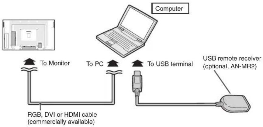
Using the remote control as the wireless computer mouse
The USB remote receiver (optional, AN-MR2) makes it possible to operate the monitor with the remote control. For details, see the operation manual of the receiver.
flowchart
graph TD
    A["Computer"] -->|To Monitor| B["RGB, DVI or HDMI cable (commercially available)"]
    A -->|To PC| C["USB remote receiver (optional, AN-MR2)"]
    A -->|To USB terminal| D["USB remote receiver (optional, AN-MR2)"]
The mouse pointer can be operated in the following way after it is connected.
When moving the cursor:
Press Adjustment/MOUSE (▲/▼/◄/►).
When left-clicking:
Press L-CLICK.
When right-clicking:
Press R-CLICK.
When your computer supports only a one-click mouse (such as Macintosh):
Press L-CLICK or R-CLICK.
L-CLICK and R-CLICK have common function.
When using [Page Up] or [Page Down]:
Same as the [Page Up] and [Page Down] keys on a computer keyboard.
Press PAGE UP or PAGE DOWN.

Note
- This function only works with the Microsoft® Windows® OS and Mac OS®. However, this function does not work with the following operation systems that do not support USB.
- Versions earlier than Windows ^ 95
- Versions earlier than Windows® NT4.0
- Versions earlier than Mac OS ^ 8.5
- You cannot use this function when displaying the menu screen.
- Confirm that the computer recognizes the USB remote receiver connection.
Menu Operations
- You need to bring up the On-Screen Display to perform settings for the monitor. The On-Screen Display for the settings is called "Menu".
- The Menu enables various settings and adjustments. (See page 31.)
- The Menu can be operated with the remote control.
Basic menu operations
1 Press MENU and the MENU screen appears.
![MENU [Picture] Picture Audio Power Control AV Mode [Standard] OPC [Off] Backlight [+16] Contrast [ 30] Brightness [ 0] Color [ 0] Tint [ 0] Sharpness [ 0] Red [ 0] Green [ 0] Blue [ 0] Advanced Reset](/content/2026/06/1181510/images/2ee4a0a5ef00acb9ba62c7d50d48f136d42ddec28c4c4e0146401970583bd3bc.jpg)
2 Press ◀/▶ to select the desired menu.
![Audio Power Control Standard Treble [0] - Bass [0] - Balance [0] L Reset](/content/2026/06/1181510/images/e78a1b3e041e200602ce8af0f0fbb464fbb9ea369fb5e7d243eddc224a2915c6.jpg)
3 Press ▲/▼ to select the desired menu item. Press ENTER to proceed if necessary.
![Audio Power Control Standard Treble [ 0] - + Bass [ 0] - + Balance [ 0] L R Reset](/content/2026/06/1181510/images/3f8236b0c43b3bbf00152f7a9ae01957ff9e39662e2d849df5dc635538247841.jpg)
4 Press ▲/▼ or ◀/► to select the desired item or adjust the item to the desired level.
Press ENTER if necessary.
5 Press MENU to exit the MENU.
Press RETURN as necessary to return to the previous MENUs.
■ Using the control panel of the monitor
You can also operate the Menu using the control panel of the monitor. Button operations on the control panel correspond to the ones on the remote control.

Note
- Menu options differ in the selected input modes, but the operating procedures are the same.
- The screens in the operation manual are for explanation purposes (some are enlarged, others cropped) and may vary slightly from the actual screens.
■ About Guide Display
The Guide Display at the bottom of the screen shows operations with an On-Screen Display.

The bar above is an operational guide for the remote control. The bar will change in accordance with each menu setting screen.
List of menu items

Picture
AV Mode Page 32
OPC Page 32
Backlight Page 32
Contrast Page 32
Brightness Page 32
Color Page 32
Tint Page 32
Sharpness ......Page 32
Red Page 32
Green Page 32
Blue Page 32
Advanced Color Temp. ......Page 33
DNR Page 33
Film Mode Page 33
Black Page 33
3D-Y/C Page 33
Monochrome Page 33
Reset Page 32

Audio
AV Mode Page 32
Treble Page 34
Bass Page 34
Balance Page 34
Reset Page 34

Power Control
Power Management ......Page 34
No Operation Off Page 34
Ecology Page 35

Note
- Some menu items may not be displayed depending on the selected input source.

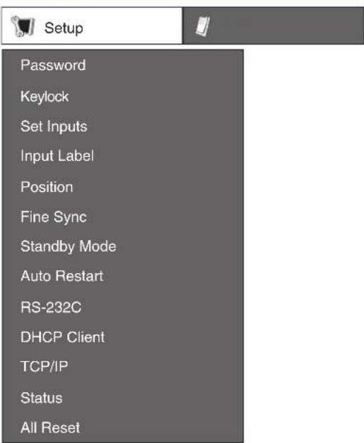
Setup
Password ......Page 35
Keylock
Main Set Page 36
Remote Control Page 36
Set Inputs ......Page 36
Input Label Page 37
Position
H-Position Page 37
V-Position Page 37
Reset Page 37
Fine Sync
Resolution ......Page 37
Signal Info Page 37
Auto Sync Page 37
H-Position Page 38
V-Position Page 38
Clock Page 38
Phase Page 38
Reset Page 38
Standby Mode ......Page 38
Auto Restart Page 38
RS-232C Page 38
DHCP Client Page 38
TCP/IP Page 39
Status Page 39
All Reset Page 39

Option
Closed Caption ......Page 40
Audio Output Page 40
Video System ......Page 41
Signal Type
Computer1 Page 41
Computer2 Page 41
DVI Page 41
HDMI Page 41
Color Space Page 41
Dynamic Range
DVI Page 42
HDMI Page 42
Language......Page 42
HDMI Setup
Auto View Page 42
Audio Select Page 42
Resize Page 42
Timer
Clock Page 42
Schedule Page 43
Sleep Timer Page 43
Picture Flip Page 43
Multi Screen
Status ......Page 44
Position Page 44
H-Bezel Page 44
V-Bezel Page 44
H-Position Page 44
V-Position Page 44
Reset Page 44
Power On Delay ......Page 44
LED Page 44
Background Page 44
Picture menu
![MENU [Picture] Picture Audio Power Control AV Mode [Standard] OPC [Off] Backlight [+16] Contrast [ 30] Brightness [ 0 ] Color [ 0 ] Tint [ 0 ] Sharpness [ 0 ] Red [ 0 ] Green [ 0 ] Blue [ 0 ] Advanced Reset](/content/2026/06/1181510/images/c66ee92783616315aa493f0a3eb2afcfbeeebcf7801ef7be66ae5a56c60a511b.jpg)
■ Selecting a preset AV Mode
The AV Mode function enables you to select appropriate settings for picture and audio to account for the system environment which can vary due to factors like room brightness or the type of image input from external equipment.
| Selectable items | Description |
| Standard For | standard image |
| Presentation | Brightens portions of image for more enhanced presentations. |
| Movie Gives | natural tint to the image. |
| Game Gives | sharpness to the image. |
| *sRGB | For high fidelity reproduction of images from a computer. |
- You can set or adjust each item in the "Picture" menu to your preference. Any changes you make are retained in memory.

Note
- You can also press AV MODE on the remote control to select the AV Mode. (See page 27.)
- *sRGB is an international standard of color reproduction regulated by the IEC (International Electrotechnical Commission). As the fixed color area has been decided by the IEC, the images are displayed in a natural tint based on an original image, when "sRGB" is selected. For additional information about the sRGB function, visit "http://www.srgb.com/". You cannot set the items, "Red", "Green", "Blue", "Color Temp.", when "sRGB" is selected.
- When "sRGB" is selected, the image may become dark, but this does not indicate a malfunction.
■ Picture adjustment
You can adjust the picture to your preference.

Note
- "Backlight" cannot be adjusted when "OPC" is set to "On" or "On(Display)".
| Selectable items | ◀button | ▶button |
| OPC | Sets whether or not the screen brightness is automatically adjusted according to the lighting condition in the room. (OPC setting: See page 33.) | |
| Backlight | The screen dims | The screen brightens |
| Contrast | For less contrast | For more contrast |
| Brightness | For less brightness | For more brightness |
| Color | For less color intensity | For more color intensity |
| Tint | Skin tones become purplish | Skin tones become greenish |
| Sharpness | For less sharpness | For more sharpness |
| Red ^1 | For weaker red | For stronger red |
| Green ^1 | For weaker green | For stronger green |
| Blue ^1 | For weaker blue | For stronger blue |
| Advanced ^2 | For finer picture adjustments. (See page 33.) | |
| Reset | Resets all picture adjustment items to the factory preset values. | |
*1 Not adjustable/selectable when selecting "sRGB".
*2 "Color Temp." is not adjustable/selectable when selecting "sRGB".
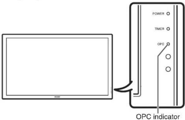
OPC (Optical Picture Control) setting
You can set the monitor to automatically adjust the screen to suitable backlight brightness according to the lighting conditions.
| Selectable items | Description |
| On(Display) Displays the OPC effect on the screen while adjusting the brightness of the screen. | |
| On Automatically adjusts | |
| Off The brightness is fixed at the value set in “Backlight”. (See page 32.) | |
OPC indicator
| Light off “Off” is selected in the OPC setting. |
| Lighted (Green) “On” or “On(Display)” is selected in the OPC setting. |

Note
- Make sure no object obstructs the OPC sensor, which could affect its ability to sense surrounding light.
■ Advanced picture settings
The advanced settings enable you to set the picture adjustment in more detail. There are 6 options you can choose from.
Color Temp. (Color Temperature)
Adjusts the color temperature to give the best white image.
| Selectable items | Description |
| High White with bluish toneMid-HighMiddleMid-LowLow White with reddish tone |
DNR (Digital Noise Reduction)
Reduces noise on the screen and produces a clearer video image.
Film Mode
Automatically detects a film-based source (originally encoded at 24/25 frames/second, depending on the vertical frequency), analyses it then recreates each still film frame for high-definition picture quality.

Note
- This model is not compatible to 1080/24P input signal.
Black
For easier viewing, change the viewing depth by selecting a level for automatically adjusting the dark portion of an image.
| Selectable items | Description |
| On For high detail in black portions | |
| Off No adjustment | |
3D-Y/C
Provides high quality images with minimal dot crawl and cross color noise.
| Selectable items | Description |
| Standard Normal | adjustment |
| Fast For movie image | |
| Slow For still image | |
| Off 3D-Y/C off | |

Note
- 3D-Y/C is not selectable depending on the input signal type.
- 3D-Y/C may not operate depending on the input signal type or noisy input signal.
Monochrome
For viewing images in monochrome.
Audio menu
![Audio Power Control Standard Treble [ 0] - Bass [ 0] - Balance [ 0] L Reset + + + R](/content/2026/06/1181510/images/641785c08099e11d86cee60b0ee57b837ffb10a7bb5565eb0c3a2acc5bb20a45.jpg)
■ Audio adjustment
You can adjust the audio of the selected AV mode.
| Selectable items | ◀button | ▶button |
| Treble For | weaker treble For stronger treble | |
| Bass For | weaker bass For stronger bass | |
| Balance D | decrease audio from the right speaker | Decrease audio from the left speaker |

Note
- For resetting all adjustment items to the factory preset values, press ▲/▼ to select "Reset", press ENTER, press ▲/▼ to select "Yes", and then press ENTER.
Power Control menu
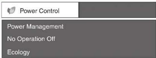
■ Power Management
You can set the monitor to automatically power off when there is no image displayed on the computer.
| Selectable items | Description |
| Off • No power managementFactory preset value. | |
| Mode1 • If no signal inputs for approximately 8 minutes, the power shuts down.Even if you start using the computer and the signal inputs again, the monitor stays off.The monitor turns on again by pressing ON on the remote control. | |
| Mode2 • If no signal inputs for approximately 8 seconds, the power shuts down.When you start using the computer and the signal inputs again, the monitor turns on. | |

Note
- If you turn off the power by disconnecting the power cord when setting "Mode2" in power management, the monitor may not function properly after turning the power on again. In such case, press ON on the remote control.
- Pressing POWER on the monitor will have the same result.
■ Auto power-off when there are no operations performed (No Operation Off)
You can set the monitor to automatically power off when no operation is performed for more than 30 minutes or 3 hours.

Note
- "Disable" is the factory preset value.
Ecology
When set to "Yes", The monitor activates the following power saving mode.
- "OPC" set to "On" (Page 33)
- "Standby Mode" set to "Mode2" (Page 38)
- "No Operation Off" set to "3 Hours" (Page 34)
• "Power Management" set to "Mode1" (Page 34)

Note
- Ecology mode cannot be deactivated by selecting "No". Each setting must be changed individually to deactivate Ecology mode.
Setup menu
■ Setting a password (Password)
If you do not want others to change the setting for the "Setup" menu, set a password.
1 Select "Password", then press ENTER.
- The screen for entering the password appears.
![MENU [Setup---Password] Enter your new password. Use 4 digits. Old Password New Password Reconfirm](/content/2026/06/1181510/images/4c9b072052681adda9b616a86a7226ae53976b7ba4372aae407115e300a30a93.jpg)
2 Press ▲/▼ to set the first digit in "New Password", then press ▶.
3 Enter the remaining 3 digits, then press ENTER.
• To return to the previous digit, press ◀.
4 Enter the same password in "Reconfirm", then press ENTER.
- The status for "Password" changes to


Note
- Once the password is set, you must enter the password to change the "Setup" menu settings.
Menu operations
Changing the password
1 Select "Password", then press ENTER.
• The screen for entering the password appears.
2 Enter the password in "Old Password" using ▲/▼/◄/►, then press ENTER.
3 Enter the password in "New Password" using ▲/▼/◄/►, then press ENTER.
4 Enter the same password again in "Reconfirm" using ▲/▼/◄/►, then press ENTER.

Note
- If you do not need the password protection for the "Setup" menu settings anymore, press ENTER without entering new password in steps 3 and 4.
- To cancel the password settings, pressRETURN.
If you forget the password
If you forget the password, perform the following procedure to delete it, then set a new password.
On the remote control or the monitor, press ◀ → ENTER → ▶ → ENTER → ◀ → ENTER → MENU.
Keylock
You can disable operations on the monitor and the remote control that use buttons.
| Selectable Items | Description | |
| Main Set | Off Enables operation. | |
| Level1 | Only the POWER button on the monitor is available. | |
| Level2 | All of the operation buttons on the monitor are unavailable. | |
| Remote Control | Off Enables operation. | |
| Level1 | Only the ON/STANDBY buttons on the remote control are available. | |
| Level2 | All of the operation buttons on the remote control are unavailable. | |

Note
When you cannot unlock the operation buttons using the menu, for example, when all of the operation buttons on the monitor and the remote control are locked simultaneously, follow the steps below.
- To unlock all of the buttons on the monitor and the remote control: Press and hold ENTER (monitor/remote control) for 5 seconds when no on-screen displays are displayed. If the password is set, the screen for entering the password appears. Enter the password using ▲/▼/◄/► (monitor/remote control).
• To unlock the buttons on the monitor:
1) Press and hold POWER on the monitor for 5 seconds to turn off the main power.
2) Press and hold POWER on the monitor for 5 seconds to unlock the monitor buttons.
■ Bypassing unused input selections (Set Inputs)
This function allows you to skip the input mode that you rarely use. You can skip the input modes when pressing INPUT on the monitor.
| Selectable items Description | ||
| Computer1 Computer2 DVI HDMI S-VIDEO VIDEO | On | Sets the input mode as “selectable”, respectively. |
| Off | Sets the input mode as “unavailable”, respectively. | |
■ Labelling input sources (Input Label)
You can assign each input source a label as you prefer.
1 Press COMPUTER (1/2), DVI, HDMI, S-VIDEO or VIDEO to select the desired input source.
2 Press MENU and the MENU screen appears.
3 Press ◀/▶ to select "Setup".
4 Press ▲/▼ to select "Input Label", and then press ENTER.
- When an HDMI input terminal is selected, a Menu screen for selecting "Auto" or "Manual" is displayed.
- When you select "Auto" using ▲/▼, the Menu screen returns to the previous screen.
- When you select "Manual" using ▲/▼, the screen for labelling the input source appears. Proceed to step 5.
5 Press ▲/▼ to select characters and ◀/▶ to move to the desired digit to label the input source.
- When you want to change the input label that you have already assigned to the default name, press ◀/▶ to move to "CLEAR" on the "Input Label" screen, and then press ENTER.
6 Repeat the above until the name is fully spelled out, and then press MENU.
- The name can be 9 characters or less.
- When you want to set an input source name of less than 9 characters, press MENU to exit from the labelling menu.
■ Adjusting the image position (Position)
For adjusting a picture's horizontal and vertical position.
| Selectable Items | Description |
| H-Position Centers the image by moving it to the left or right. | |
| V-Position Centers the image by moving it up or down. | |

Note
- For resetting all adjustment items to the factory preset values, press ▲/▼ to select "Reset", press ENTER, press ▲/▼ to select "Yes", and then press ENTER.
- Adjustments are stored separately according to input source.
- Images may not be displayed properly depending on the settings and/or signals.
■ Adjusting the computer image (Fine Sync)
Resolution
Ordinarily, the type of input signal is detected and the correct resolution mode is automatically selected. However, for some signals, the optimal resolution mode on the “Resolution” menu may need to be selected to match the computer display mode.
Signal Info
Displays infomation about the input signal, such as resolution, horizontal frequency, and vertical frequency.
Auto Sync Adjustment (Auto Sync)
| Selectable items | Description |
| Yes Perform | Auto Sync adjustment. |
| No Do not perform | Auto Sync adjustment. |

Note
- Auto Sync adjustment is also performed by pressing AUTO SYNC on the remote control.
- The Auto Sync adjustment may take some time to complete, depending on the image of the computer connected to the monitor.
- When the optimum image cannot be achieved with Auto Sync adjustment, use manual adjustments. (See page 38.)
Menu operations
Adjusting the computer image manually
Ordinarily you can easily adjust the picture as necessary to change image position using "Auto Sync". In some cases, however, manual adjustment is needed to optimize the image.
| Selectable items | Description |
| H-Position Centers the image by moving it to the left or right. | |
| V-Position Centers the image by moving it up or down. | |
| Clock Adjusts when the image flickers with vertical stripes. | |
| Phase Adjusts when characters have low contrast or when the image flickers. | |

Note
- If "H-Position" and "V-Position" in "Fine Sync" are set, "H-Position" and "V-Position" in "Position" become invalid.
- For resetting all adjustment items to the factory preset values, press ▲/▼ to select "Reset", press ENTER, press ▲/▼ to select "Yes", and then press ENTER.
- Images may not be displayed properly depending on the settings and/or input signals.
■ Reducing the start-up time (Standby Mode)
You can reduce the monitor's start-up time after turning on the power with the remote control.
| Selectable items | Description |
| Mode1 | Starting the monitor is quick from standby. |
| Mode2 The RS-232C and Network functions are activated even if the monitor is in the standby mode. | |
| Mode3 Power consumption is low while in standby mode.The RS-232C and Network functions are switched off in standby mode. | |
■ Auto restart function (Auto Restart)
| Selectable items | Description |
| On If the power cord is unplugged from the outlet or the breaker switch is turned off when the monitor is on, then the monitor automatically turns on when the power cord is plugged into the AC outlet or the breaker switch is turned on. | |
| Off The monitor does not turn on automatically when the power cord is plugged into the AC outlet or the breaker switch is turned on. | |
■ Selecting the transmission speed (RS-232C)
Make sure that both the monitor and computer are set for the same baud rate.
| Selectable items | Description |
| 9600bps Transmission speed is slow.115200bps Transmission speed is rapid. | |
■ DHCP client setting (DHCP Client)
Connect the LAN cable before turning the monitor on. If not, the DHCP Client function does not work.
| Selectable items | Description |
| On Obtains | configuration parameters for TCP/IP network automatically. |
| Off Sets the | TCP/IP manually. |
Select "On" for "DHCP Client". "Obtaining IP Address..." appears, then the menu screen appears. Confirm the parameters of IP Address, Subnet Mask and Gateway on the TCP/IP screen. If the DHCP server is not available, "Could not obtain IP Address." appears. In this case, set the TCP/IP manually. (See page 39.)
■ TCP/IP setting (TCP/IP)
Set the TCP/IP manually.
1 Select "Off" for "DHCP Client", then press ENTER.
2 Select "TCP/IP", then press ENTER.
3 Enter "IP Address" using ▲/▼/◄/►, then press ENTER.
MENU [Setup---TCP/IP]
| IP Address | 192.168.150.002 |
| Subnet Mask | 255.255.255.000 |
| Gateway | 000.000.000.000 |
4 Enter "Subnet Mask" using ▲/▼/◄/►, then press ENTER.
5 Enter "Gateway" using ▲/▼/◄/►, then press ENTER.
| Selectable items | Description |
| IP Address | Factory default setting:192.168.150.002Enter an IP address appropriate for the network. |
| Subnet Mask | Factory default setting:255.255.255.000Set the subnet mask to the same as that of the computer and equipment on the network. |
| Gateway Factory default setting:000.000.000.000* When not in use, set to “000.000.000.000”. | |

Note
- Confirm the existing network's segment (IP address group) to avoid setting an IP address that duplicates the IP addresses of other network equipment or computers. If "192.168.150.002" is not used in a network with an IP address of "192.168.150.XXX", you don't have to change the monitor IP address.
- For details about each setting, consult your network administrator.
■ Confirming the monitor information (Status)
You can confirm the following information.
- DHCP Client
- IP Address
- Subnet Mask
- Gateway
- MAC Address
- Monitor Name
- Serial Number

Note
- For information on how to change the monitor name, see "SETUP MANUAL" contained in the supplied CD-ROM.
■ Returning to the default settings (All Reset)
This function allows you to initialize the settings you have made in the monitor.
1 Press ▲/▼ to select "All Reset" and press ENTER.
2 Press ▲/▼ to select "Yes" and press ENTER.
Option menu

Option
Closed Caption
Audio Output
Video System
Signal Type
Color Space
Dynamic Range
Language
HDMI Setup
Resize
Timer
Picture Flip
Multi Screen
Power On Delay
LED
Background
■ Selecting Closed Caption (Closed Caption)
This monitor is equipped with an internal Closed Caption decoder. It allows you to view conversations, narration and sound effects as subtitles on your monitor. Closed Captions are available on some TV programs and on some VHS home video tapes at the discretion of the program provider.

Note
- 4 kinds of closed caption service (CC1, CC2, Text1, Text2) are potentially available, but a broadcast may contain none or only some of these services at the discretion of the program provider.
- While displaying on-screen displays, Closed Caption information disappears.
■ Setting the audio output type (Audio Output)
This function determines whether the audio level output from the audio output terminal is fixed or variable by linking with VOLUME.
| Selectable items | Description |
| FAO (Fixed Audio Output) | Audio output that does not vary in strength with the volume level of the source monitor. |
| VAO (Variable Audio Output) | Audio output that varies in strength with the volume level of the source monitor. |

Note
- When "Audio Output" is set to "VAO", sound via speakers is muted.
- When "Audio Output" has been set to "VAO", first make sure to lower the volume of the monitor before turning the power on or off and when switching the input.
- When the monitor is connected to audio equipment:
-- It is recommended that "FAO" be selected on "Audio Output". Because the audio signal from the audio equipment does not vary in strength with the volume level of the monitor, you can enjoy better sound.
-- When "FAO" is selected on "Audio Output", video and audio may not synchronize.
- When connecting audio equipment that has a function for adjusting audio delay time, adjust the delay time for synchronizing video and audio.
- When the audio equipment does not have such a function and the unsynchronized video and audio bothers you, select "VAO" on "Audio Output". Selecting "VAO" synchronizes video and audio automatically.
■ Setting the video system (Video System)
The video input system mode is factory preset to "Auto"; however, a clear picture from the connected audio-visual equipment may not be received, depending on the video signal difference. In that case, switch the video signal.
| Selectable items | Description |
| Auto The video system is automatically selected. | |
| PAL When connected to PAL video equipment. | |
| SECAM When connected to SECAM video equipment. | |
| NTSC3.58 When connected to NTSC video equipment. | |
| NTSC4.43 | When reproducing NTSC signals in PAL video equipment. |
| PAL-60 When connected to 60 Hz PAL video equipment. | |

Note
- While "Video System" is set to "Auto", when PAL-M or PAL-N signal is input, the image from PAL signal will be displayed.
■ Signal type setting (Signal Type)
This function allows you to select the input signal type Computer1, Computer2, DVI or HDMI.
| Input signal | Selectable items | Description |
| Computer 1/2 | Auto Input signals are automatically recognized as RGB or component. | |
| RGB Set when RGB signals are received. | ||
| Component | Set when component signals are received. | |
| DVI | D. PC RGB | Set when digital PC RGB signals are received from a computer. |
| D. PC Comp. | Set when digital PC component signals are received from a computer. | |
| D. VIDEO RGB | Set when digital video RGB signals are received from video equipment. | |
| D. VIDEO Comp. | Set when digital video component signals are received from video equipment. | |
| HDMI A | Auto Input signals are automatically recognized as RGB or component. | |
| RGB Set when digital video RGB signals are received from video equipment. | ||
| YCbCr4:4:4 | Set when video signals are received from video equipment. | |
| YCbCr4:2:2 | Set when video signals are received from video equipment. | |
■ Color Space
This function allows you to select ITU (International Telecommunication Union) standard color space.
| Selectable Items | Description |
| Auto Color | Space is automatically selected. |
| ITU601 The | ITU601 standard signal is selected. |
| ITU709 The | ITU709 standard signal is selected. |
Menu operations
■ Dynamic Range
This function allows you to select the black level range (the range between the minimum and maximum brightness) for the DVI or HDMI input signals.
| Input signal | Selectable items | Description |
| DVI Sta | Standard Reproduces black level range normally. | |
| Enhanced Reproduces black level range more extensively. | ||
| HDMI Auto Looks at the AVI packet information of the HDMI signal and automatically selects the dynamic range. | ||
■ Selecting the on-screen display language (Language)
The monitor can switch the on-screen display language among 7 languages.
English
Deutsch
Español
Nederlands
Français
Italiano
日本語
■ HDMI (High-Definition Multimedia Interface) setup
This function allows you to select the Resize mode and audio of the HDMI input signal.
| HDMI Setup items | Selectable items | Description |
| Auto View Enable/Disable | Set whether or not to use Resize mode based on signal recognition, including an HDMI signal. | |
| Audio Select | Digital/Analog | Select “Digital” for audio signal via the HDMI terminal. Select “Analog” for audio signal via the audio input terminal. |

Note
- Refer to your external equipment operation manual for the above settings.
- When connecting a DVI-HDMI conversion adaptor/cable to the HDMI terminal, the image may not come in clearly.
■ Setting the resize mode (Resize)
This function allows you to modify or customize the Resize mode to enhance the input image.

Note
- For details of the Resize mode, see pages 25 and 26.
- You can also press RESIZE on the remote control to set the resize mode. (See page 25.)
Timer
You can set the time to switch the monitor on and off.
1 Press MENU and press ◀/▶ to select "Option".
2 Press ▲/▼ to select "Timer", and press ENTER.
Clock
Sets the current day and time.
1 Press ▲/▼ to select "Clock", and press ENTER.
2 Press ◀/▶ to select items, and press ▲/▼ to change the setting.
3 Press ENTER.
"Clock" setting becomes effective.
Schedule
Sets the schedule to switch the monitor on and off.
1 Press ▲/▼ to select "Schedule", and press ENTER.
![MENU [Option--Timer] Clock Schedule Sleep Timer Present time : 1:02 (Mon) Status No. Week On Off Time On Off Input 1 Off - - - - - - - - - - - - - - - - - - - - - - - - - - - - - - - - - - - - - - - - - - - - - - - - - - - - - - - - - - - - - - - - - - - - - 2 Off - - ~ ~ ~ ~ ~ ~ ~ ~ ~ ~ ~ ~ ~ ~ ~ ~ ~ ~ ~ ~ ~ ~ ~ ~ ~ ~ ~ ~ ~ ~ ~ ~ ~ ~ ~ ~ ~ ~ ~ ~ ~ ~ ~ ~ ~ ~ ~ ~ ~ ~ ~ ~ ~ ~ ~ ~ ~ ~ ~ ~ ~ ~ ~ ~ ~ ~ ~ ~ ~ ~ ~ ~ ~ ~ ~ ~ ~ ~ ~ ~ ~ ~ ~ ~ ~ ~ ~ ~ ~ ~ ~ ~ ~ ~ ~ ~ ~ ~ ~ ~ %- 3 Off - - ~ ~ ~ ~ ~ - - - - - - - - - - - - - - - - - - - - - - - - - - - - - - - - - - - - - - - - - 4 Off - - % % % % % % % % % % % % % % % % % % % % % % % % % % % % % % % % % % % % % % % % % % % % % % % % % % % % % % % % % % 5 Off - % % % % % % % % % % % % % % % % % % % % % % % % % % % % % % % % % % % % % % % % % % % % % % % % % % % % % % % 6 Off - % % % % % % % % % % % % % % % % % % % % % % % % % % % % % % % % % % % % % % % 7 Off -%~%~%~%~%~%~%~%~%~%~%~%~%~%~%~%~%~%~%~%~%~%~%~%~%~%~%~%~%~%~%~%~%~%~% 8 Off-~%~%~%~%~%~%~%~%~%~%~%~%~%~%~%~%~%~%~%~%~%~%~%~%~%~%~%~% Reset](/content/2026/06/1181510/images/1d41508f82b7d4266ec4af886b14f2861c0fbc9f3884a8678a1924d298d9cfb0.jpg)
2 Press ▲/▼ to select the Schedule number, and press ENTER.
3 Set the Schedule. Press ◀/▶ to select items, and press ▲/▼ to change the setting.
4 Press ENTER. "Schedule" setting becomes effective.
| Selectable items | Description | |
| Status | Weekly | Executes the Schedule on the specified day of the week every week. |
| Daily | Executes the Schedule every day regardless of the week. | |
| Once | Executes the Schedule once on the specified day. | |
| Off Schedule not effective. | ||
| Week Specifies | the day of the week to execute the Schedule. | |
| Time Specifies | the time to execute the Schedule. | |
| Input Specifies | the input mode at power-on. When not specifying, the screen at the previous power-off appears. | |
!Caution
- Do not switch off the power after setting the Schedule.
- Specify the correct day and time using "Clock" before setting "Schedule". "Schedule" does not function unless the day and time are specified.

Note
- Set time On and Off values that are within 12 hours of each other.
- Up to 8 Schedule items can be registered.
- When "Schedule" is set, the TIMER indicator lights red.
- A Schedule that has a large number has precedence over that of a small number when schedules overlap.
- For resetting all adjustment items to factory preset values, while selecting the Schedule number, press ▲/▼ to select "Reset", and press ENTER.
Sleep Timer
Sets the time to switch the monitor off. (1-12 hours)
1 Press ▲/▼ to select "Sleep Timer", and press ENTER.
2 Press ▲/▼ to change the setting.
3 Press ENTER.
"Sleep Timer" setting becomes effective.

Note
- When "Sleep Timer" is set, the TIMER indicator lights red.
■ Picture Flip
A picture flips to appear.
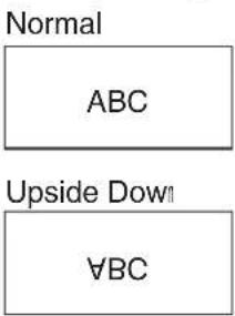
Menu operations
■ Multi Screen
You can align 2, 3, 4, 9, or 16 monitors and integrate them into a single large screen to display.
Enlarged views of separated images are displayed in each monitor.
| Selectable items | Description |
| Status Sets | the number of screen splits used for the enlargement. |
| Position Specify | the split screen to be displayed when this function is used. |
| H-Bezel | Sets the frame width of the display when this function is used. |
| V-Bezel | |
| H-Position Adjust the horizontal position of the enlarged screen. | |
| V-Position | Adjust the vertical position of the enlarged screen. |
| Reset Resets | all adjustment items to factory preset values. |
2 monitors (2x1)

3 monitors (3x1)
4 monitors (4x1)
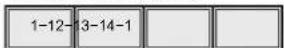
4 monitors (2x2)
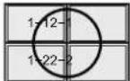
9 monitors (3x3)
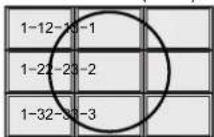
16 monitors (4x4)
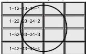

Note
- The availability of Multi Screen modes depending on the video signal is as follows.
| Input Mode | Video Signal | 3x1 | 4x1 | 3x3 | 4x4 | |
| S-VIDEOVIDEO | NTSC N/A | N/A | N/A | N/A | ||
| PAL N/A | N/A | N/A | N/A | |||
| SECAM N/A | N/A | N/A | N/A | |||
| Computer1Computer2 | 480I N/A | N/A | ||||
| 576I N/A |
N/A: Not Available
- "Status" and "Position" may not be selected depending on the input signal.
- Depending on the number of monitors and/or the input signal, a distributor for the input signal (commercially available) is required. For details, refer to the "SETUP MANUAL".
■ Power On Delay
You can delay the screen display after the monitor is turned on. The period can be set up to 100 seconds in units of 1 second. When this function is activated, the POWER indicator flashes (at approx. 1 second interval) in orange. This function is disabled when 0 is specified.
LED
Specifies whether to light the indicators (POWER, TIMER, and OPC).
| Selectable items | Description |
| On | According to the setting, the indicators light up. |
| Off | The indicators do not light up. |

Note
- Even if "LED" is set to "Off", the POWER indicator lights red in standby mode.
- When backlight and/or temperature problems occur, the TIMER indicator flashes red, even if "LED" is set to "Off".
■ Selecting the background image (Background)
| Selectable items | Description |
| Blue | Blue screen |
| None | Black screen |
Troubleshooting
The Problems described below are not always caused by malfunctions. Check the monitor again before having the monitor serviced.
| Problems Solution | |
| There is no picture or sound. | Is the power cord disconnected? (See page 21.)Has the power been turned on? (See page 23.)Check if you pressedON on the remote control. (See page 23.)If the POWER indicator on the monitor lights up red, press ON on the remote control.Power to the external connected devices is off.Is the connection to external equipment correct? (See page 16.)Is the correct input mode selected? (See page 24.)Has the input signal setup been performed correctly after connection? (See page 16.) |
| Remote control does not operate. | Are batteries inserted with polarity (+,-) aligned? (See page 22.)Are batteries worn out? Replace with new batteries. (See page 22.)Are you using it under strong or fluorescent lighting?Is a fluorescent light shining on the remote control sensor? |
| There is a picture but no sound. | Is the sound muted? (See page 24.)Make sure the volume is not set to minimum. (See page 24.)Are audio cables and speaker cables connected properly? (See pages 18 and 19.)Is the audio signal input properly to the selected audio input terminal? (See page 18.)Is “FAO” selected for “Audio Output” in the “Option” menu? (See page 40.) |
| Picture is cut off.Black bands appear at the edges of the screen. | Is the image position correct? (See page 37.)Are screen mode adjustments such as picture size made correctly? (See page 25.) |
| Strange color, light color, or color misalignment. | Check the color adjustments and tint settings. (See page 32.)Check the signal type setting. (See page 41.) |
| Unstable picture. | Is a non-compatible signal being input? (See page 49.)Try the AUTO SYNC button on the remote control. (See page 27.) |
| TIMER indicator flashes red.Power is suddenly turned off. | The unit’s internal temperature has increased.Check whether the monitor is placed at a location where a quick rise in temperature is likely. Internal temperature rises quickly if the vents on the monitor are blocked.Internal temperature rises quickly if dust accumulates inside the monitor or around the vents. Remove dust if possible. Consult a Sharp Authorized Dealer about removing internal dust. |
| Power and picture change automatically. | Is “Sleep Timer” and/or “Schedule” set? (See page 43.)Check the power control setting. (See pages 34 and 35.) |
| The unit’s plastic parts make a cracking noise. | When the ambient temperature changes, the unit’s plastic parts will slightly expand or shrink. This will cause a cracking noise. This is not a fault, it will not affect the unit’s performance. |
Cautions regarding use in high and low temperature environments
- When the unit is used in a low temperature space (e.g. room, office), the picture may leave trails or appear slightly delayed. This is not a malfunction, and the unit will recover when the temperature returns to normal.
- Do not leave the unit in a hot or cold location. Also, do not leave the unit in a location exposed to direct sunlight or near a heater, as this may cause the cabinet to deform and the LCD panel to malfunction.
- Storage temperature: -4^ to +140^ (-20°C to +60°C).
This unit is equipped with a microprocessor. Its performance could be adversely affected by incorrect operation or interference. If this should happen, unplug the unit and plug it in again after more than 5 minutes.
For SHARP Assistance
If you encounter any problems during setup or operation of this monitor, first refer to the “Troubleshooting” section on page 45. If this operation manual does not answer your question, please contact the SHARP Service departments listed below.
U.S.A. Sharp Electronics Corporation
1-888-GO-SHARP (1-888-467-4277)
lcdsupport@sharpsec.com
http://www.sharpusa.com
Canada Sharp Electronics of Canada Ltd.
(905) 568-7140
http://www.sharp.ca
Mexico Sharp Electronics Corporation Mexico Branch
(525) 716-9000
http://www.sharp.com.mx
Latin America Sharp Electronics Corp. Latin American Group
(305) 264-2277
www.servicio@sharpsec.com
http://www.siempresharp.com
Germany Sharp Electronics (Europe) GMBH
01805-234675
http://www.sharp.de
U.K. Sharp Electronics (U.K.) Ltd.
08705 274277
http://www.sharp.co.uk/customersupport
Italy Sharp Electronics (Italy) S.P.A.
(39) 02-89595-1
http://www.sharp.it
France Sharp Electronics France
01 49 90 35 40
hotlineced@sef.sharp-eu.com
http://www.sharp.fr
Spain Sharp Electronica Espana, S.A.
93 5819700
sharplcd@sees.sharp-eu.com
http://www.sharp.es
Switzerland Sharp Electronics (Schweiz) AG
0041 1 846 63 11
cattaneo@sez.sharp-eu.com
http://www.sharp.ch
Sweden Sharp Electronics ( Nordic ) AB
(46) 8 6343600
vision.support@sen.sharp-eu.com
http://www.sharp.se
Austria Sharp Electronics (Europe) GMBH Branch Office Austria
0043 1 727 19 123
pogats@sea.sharp-eu.com
http://www.sharp.at
Benelux SHARP Electronics Benelux BV
0900-SHARPCE (0900-7427723) Neder-
land
9900-0159 Belgium
http://www.sharp.nl
http://www.sharp.be
http://www.sharp.lu
Australia Sharp Corporation of Australia Pty. Ltd.
1300-135-022
http://www.sharp.net.au
New Zealand Sharp Corporation of New Zealand
Phone: (09) 573-0111
Fax: (09) 573-0112
http://www.sharp.net.nz
Singapore Sharp-Roxy Sales (S) Pte. Ltd.
65-226-6556
ckng@srs.global.sharp.co.jp
http://www.sharp.com.sg
Hong Kong Sharp-Roxy (HK) Ltd.
(852) 2410-2623
dcmktg@srh.global.sharp.co.jp
http://www.sharp.com.hk
Taiwan Sharp Corporation (Taiwan)
0800-025111
http://www.sharp-scot.com.tw
Malaysia Sharp-Roxy Sales & Service Co.
(60) 3-5125678
U.A.E. Sharp Middle East Fze
971-4-81-5311
helpdesk@smef.global.sharp.co.jp
Thailand Sharp Thebnakorn Co. Ltd.
02-236-0170
svc@stcl.global.sharp.co.jp
http://www.sharp-th.com
Korea Sharp Electronics Incorporated of Korea
(82) 2-3660-2002
lcd@sharp-korea.co.kr
http://www.sharpkorea.co.kr
India Sharp Business Systems (India)
Limited
(91) 11-6431313
service@sharp-oa.com
Specifications
■ Product specifications
| ModelItem | TL-M5200 | TL-M4600 | ||
| LCD Panel ASV low-reflection black TFT LCD | ||||
| Screen size 52 | ^1/_32" (1322 mm measured diagonally) | 45^63/_64" (1168 mm measured diagonally) | ||
| Active View SizeWide x High | 45^23/_64" × 25^33/_64" (1152 mm x 648 mm) | 40^3/_32" × 22^9/_16" (1018 mm x 573 mm) | ||
| Number of pixels 2,073,600 pixels (1920 x 1080) | ||||
| Pixel pitch 0.600 mm (H) x 0.600 mm (V) 0.530 mm (H) x 0.530 mm (V) | ||||
| Brightness 450 cd/m | ^2 | 400 cd/m ^2 | ||
| Maximum colors 16.77 Million colors (8 bits/color) | ||||
| Viewing angle Horizontal 176°/Vertical 176° (contrast ratio ≥ 10 ) | ||||
| Backlight life (Approx.) 60,000 Hours ^-1 (at Backlight Standard position) | ||||
| Audio amplifier 15 W x 15 W (4 Ω) | ||||
| Terminals | Rear | Computer input 1Audio input | Mini D-sub 15-pin (RGB/Component ^*3 )∅3.5 mm stereo minijack | |
| Computer input 2Audio input | 5BNC ^-2 (RGB/Component ^*3 )∅3.5 mm stereo minijack | |||
| Monitor outputAudio output | Mini D-sub 15-pin (RGB/Component ^*3 )∅3.5 mm stereo minijack | |||
| Speaker output | LR push terminal type | |||
| LAN | RJ-45 8-pin modular | |||
| RS-232C | D-sub 9-pin | |||
| DVI-D ^4 Audio input | 24-pin (Compatible with HDCP)∅3.5 mm stereo minijack | |||
| HDMI input | 19-pin (Compatible with HDCP) | |||
| Side | S-Video inputVideo inputAudio input | Mini Din 4-pinRCARCA | ||
| OSD language English/French/Spanish/Italian/German/Dutch/Japanese | ||||
| External control | LAN, RS-232C | |||
| Power Requirement | AC 100-240 V, 50/60 Hz | |||
| Power Consumption | 312 W, 3.2 A | 278 W, 2.8 A | ||
| Standby Power Consumption | TL-M5200: 33 W (Mode1), 1.4 W (Mode2), 0.3 W (Mode3) at AC 120 VTL-M4600: 30 W (Mode1), 1.4 W (Mode2), 0.3 W (Mode3) at AC 120 V | |||
| Weight | 61.8 lbs./28.0 kg (without Setup Stand) | 48.5 lbs./22.0 kg (without Setup Stand) | ||
| Dimension (W x H x D)(without Setup Stand) | 48^61/_64" × 28^43/_64" × 3^63/_64" (1243 mm x 728 mm x 101 mm) | 43^43/_64" × 25^19/_32" × 4^11/_64" (1109 mm x 650 mm x 106 mm) | ||
| Operating Temperature | 32°F - 104°F (0°C - 40°C) | |||
| Operating Humidity | 30% - 80% (no condensation) | |||
^1 The typical period of time after which the backlight power output will have decreased by about half, given that the monitor is used continuously at 77^ F ( 25^ C) under standard lighting and brightness conditions.
^2 Plug-and-play is not supported.
^3 Cannot be used simultaneously.
^4 Connection is only allowed with an HDCP-compatible device.
As a part of our policy of continuous improvement, SHARP reserves the right to make design and specification changes for product improvement without prior notice. The performance specification figures indicated are nominal values of production units. There may be some deviations from these values in individual units.
■ Dimensional drawings
Note that the values shown are approximate values.
TL-M5200
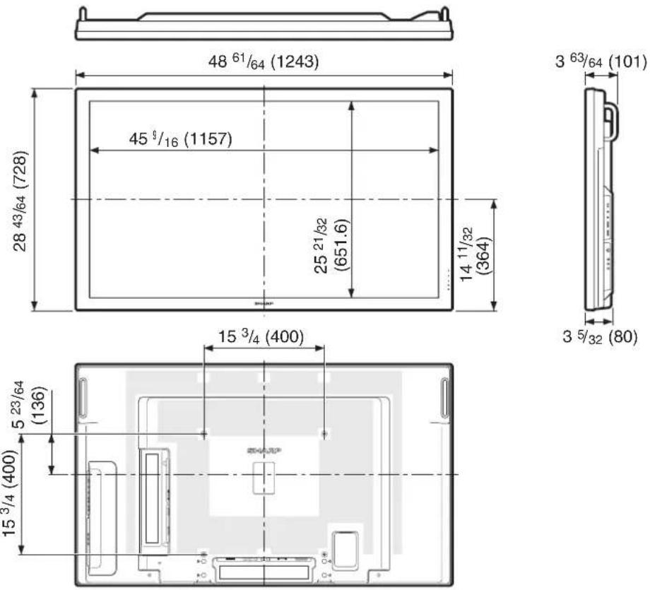
Unit: inch (mm)
TL-M4600
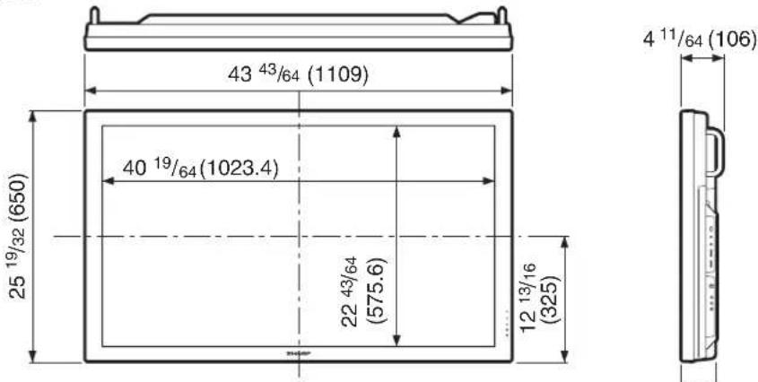
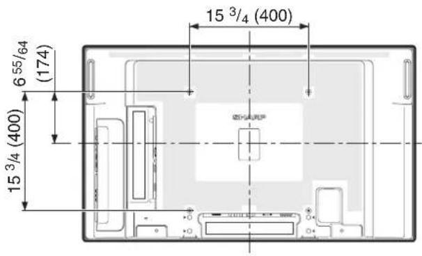
■ Computer compatibility chart
The table below shows the signal modes compatible with this device. If the display is incorrect or it does not display, please refer to the table below and adjust the output signal according to your hardware.
Computer
• Multiple signal support
Horizontal Frequency: 31-80 kHz Pixel Clock: 25-149 MHz
Vertical Frequency: 50-85 Hz Sync signal: Compatible with TTL level
- Compatible with sync on green signal
The following is a list of modes that conform to VESA. However, this monitor supports other signals that are not VESA standards.
| PC/MAC Resolution | Horizontal Frequency (kHz) | Vertical Frequency (Hz) | VESA Standard | DVI-D Support | Display | ||
| PC | VGA | 640x400 31.5 70 | √ | Upscale | |||
| 720x400 | 31.5 | 70 | √ | ||||
| 37.9 85 | √ | ||||||
| 640x480 | 31.5 | 60 | √ | √ | |||
| 37.9 72 | √ | √ | |||||
| 37.5 75 | √ | √ | |||||
| 43.3 85 | √ | ||||||
| SVGA 800x600 | 31.3 | 50 | |||||
| 35.2 | 56 | √ | √ | ||||
| 37.9 60 | √ | √ | |||||
| 48.1 72 | √ | √ | |||||
| 46.9 75 | √ | √ | |||||
| XGA 1024x768 | 48.4 60 | √ | √ | ||||
| 56.5 70 | √ | ||||||
| 58.1 72 | √ | ||||||
| 60.0 75 | √ | √ | |||||
| WXGA | 1280x720 | 44.7 60 | √ | ||||
| 1280x768 | 47.8 60 | √ | √ | ||||
| 1360x768 | 47.7 60 | √ | |||||
| SXGA 1280x1024 | 64.0 60 | √ | √ | ||||
| 80.0 75 | √ | ||||||
| SXGA+ 1400x1050 | 64.0 60 | √ | |||||
| 65.3 60 | √ | √ | |||||
| 1920x1080* | 67.5 60 | √ | True | ||||
| MAC | 13" | 640x480 35.0 67 | Upscale | ||||
| 16" | 832x624 49.7 75 | ||||||
| 21" | 1152x870 | 68.7 75 | |||||
* DVI-D only
DTV
| Signal | Horizontal Frequency (kHz) | Vertical Frequency (Hz) | DVI-D/HDMI Support (Compatible with HDCP) |
| 480I | 15.7 | 60 | |
| 480P | 31.5 | 60 | √ |
| 576I | 15.6 | 50 | |
| 576P | 31.3 | 50 | √ |
| 720P | 37.5 | 50 | √ |
| 720P | 45.0 | 60 | √ |
| 1035I | 33.8 | 60 | √ |
| 1080I | 28.1 | 50 | √ |
| 1080I | 33.8 | 60 | √ |
| 1080P | 56.3 | 50 | √ |
| 1080P | 67.5 | 60 | √ |
- Depending on the connected computer, images may not be displayed properly even if the compatible signal described above is input.
■ Power management
This monitor conforms to VESA DPMS and DVI DMPM. Both your video card and computer must support the same standard in order for the monitor's power management function to work.
DPMS: Display Power Management Signaling
| DPMS Screen | Power consumption | Hsync | Vsync | |
| ON STATE | Display | 312 W (TL-M5200)278 W (TL-M4600) | Yes | Yes |
| STANDBY | No display | 1.7 W* | No | No |
DMPM: Digital Monitor Power Management
| DMPM Screen Power consumption | ||
| Monitor ON Display | 312 W (TL-M5200)278 W (TL-M4600) | |
| Active OFF No display 1.9 W* | ||
* When "Standby Mode" is set to "Mode2". 33 W when "Standby Mode" is set to "Mode1". (TL-M5200) 30 W when "Standby Mode" is set to "Mode1". (TL-M4600)
■ DDC (plug and play)
The monitor supports the VESA DDC (Display Data Channel) standard.
DDC is a signal standard for plug and play between monitors and computers. Information about resolution and other parameters is exchanged between the two. This function can be used if the computer supports DDC and it has been configured to detect plug-and-play monitors.
There are several types of DDC, depending on the communication method used. This monitor supports DDC2B.
■ Connecting pin assignments
DVI-D input terminal: DVI-D 24 pin
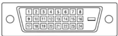
| Pin No. | Signal | Pin No. | Signal |
| 1 | T.M.D.S data 2- | 13 | Not connected |
| 2 | T.M.D.S data 2+ | 14 | +5 V power |
| 3 | T.M.D.S data 2/4 shield | 15 | GND |
| 4 | Not connected | 16 | Hot plug detection |
| 5 | Not connected | 17 | T.M.D.S data 0- |
| 6 | DDC clock | 18 | T.M.D.S data 0+ |
| 7 | DDC data | 19 | T.M.D.S data 0/5 shield |
| 8 | Not connected | 20 | Not connected |
| 9 | T.M.D.S data 1- | 21 | Not connected |
| 10 | T.M.D.S data 1+ | 22 | T.M.D.S clock shield |
| 11 | T.M.D.S data 1/3 shield | 23 | T.M.D.S clock+ |
| 12 | Not connected | 24 | T.M.D.S clock- |
RS-232C terminal: D-sub 9 pin
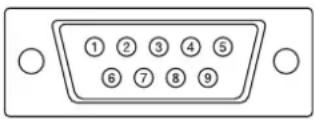
| Pin No. | Signal | Pin No. | Signal |
| 1 | Not connected | 6 | Not connected |
| 2 | Received data | 7 | Request to Send |
| 3 | Transmitted data | 8 | Clear to Send |
| 4 | Not connected | 9 | Not connected |
| 5 | GND |
RGB/COMPONENT input terminal: mini D-sub 15 pin
Pin No. Signal Pin No. Signal
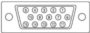
1 Video input (red) 9 +5 V power
2 Video input (green/sync on green) 10 GND
3 Video input (blue) 11 Not connected
4 Not connected 12 DDC data
5 Not connected 13 Horizontal sync signal: TTL level
6 Earth (red) 14 Vertical sync signal: TTL level
7 Earth (green/sync on green) 15 DDC clock
8 Earth (blue)
RGB/COMPONENT output terminal: mini D-sub 15 pin
Pin No. Signal Pin No. Signal
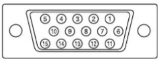
1 Video input (red) 9 Not connected
2 Video input (green/sync on green) 10 GND
3 Video input (blue) 11 Not connected
4 Not connected 12 Not connected
5 Not connected 13 Horizontal sync signal: TTL level
6 Earth (red) 14 Vertical sync signal: TTL level
7 Earth (green/sync on green) 15 DDC clock
8 Earth (blue)
LAN terminal: LAN (RJ-45)
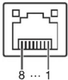
Pin No. Signal Pin No. Signal
| 1 | TX+ | 5 | |
| 2 | TX- | 6 | RX- |
| 3 | RX+ | 7 | |
| 4 | 8 |
HDMI terminal
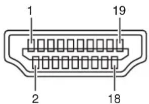
Pin No. Signal Pin No. Signal
1 T.M.D.S data 2+ 11 T.M.D.S clock shield
2 T.M.D.S data 2 shield 12 T.M.D.S clock-
3 T.M.D.S data 2-13 CEC
4 T.M.D.S data 1+ 14 Reserved
5 T.M.D.S data 1 shield 15 SCL
6 T.M.D.S data 1-16 SDA
7 T.M.D.S data 0+ 17 DDC/CEC ground
8 T.M.D.S data 0 shield 18 +5V power
9 T.M.D.S data 0-19 Hot plug detection
10 T.M.D.S clock+
Index
3D-Y/C 33
AC input terminal 10,21
All Reset 39
Assistance 46
Audio adjustment 34
Audio input terminals 11, 18
Audio Output 40
Audio output terminal 10, 18
Auto power off 34
Auto Restart 38
Auto Sync 27,37
AV Mode 27,32
AV mute 24
Background 44
Backlight 32
Brightness 32
Cable clamp 21
Clock 38,42
Closed Caption 40
Color Space 41
Color Temp. 33
Component 10, 16, 17, 18
COMPUTER IN 1/2 terminals ...... 10, 16, 17, 18
Contrast 32
DHCP Client 38
Dimensional drawings 48
DNR 33
Dot By Dot 26
DVI-D terminal 10, 16, 17
Dynamic Range 42
FAO 40
Film Mode 33
Fine Sync 37
Freeze 27
Gateway 39
HDMI 10, 17, 42
HDMI Setup 42
HDMI terminal 10, 17
Input Label 37
Input select 24
Input skip 36
IP Address 39
Keylock 36
LAN 10,20
LAN terminal 10,20
Language 42
LED 44
Magnify 27
Menu tree 31
MONITOR OUT terminals 10, 18
Monochrome 33
Mouse 29
Multi Screen 44
Network 20
OPC 32
OPC indicator, sensor 10, 33
Optional accessories 9
Password 35
Phase 38
P&P (Picture and Picture) 28
Picture Flip 43
Position 37
Power cord 21
Power Management 34
POWER indicator 10,23
Power On Delay 44
Remote control 12, 22
Remote control sensor 10, 22
Resize 25,42
RGB cable 16, 17, 18
RS-232C 38
RS-232C terminal 10, 20
Schedule 43
Setup stand 13, 14
Sharpness 32
Signal Type 41
Sleep Timer 43
SPEAKER OUT terminals 10, 19
sRGB 32
Standby Mode 38
Status 39
Stretch 25
Subnet Mask 39
Supplied accessories 9
S-VIDEO IN terminal 11, 17, 18
TCP/IP 39
Timer 42
TIMER indicator 10,43
Tint 32
VAO 40
VIDEO IN terminal 11, 17, 18
Video System 41
Volume 24
Wall mount 13, 14, 15
SHARP®
SHARP ELECTRONICS CORPORATION
Sharp Plaza, Mahwah, New Jersey 07495-1163
SHARP CORPORATION
- IMPORTANT
- IMPORTANT INFORMATION
- WARNING:
- CAUTION
- INFORMATION:
- DECLARATION OF CONFORMITY:
- Trademarks
- Additional Safety Information
- Precautions when transporting the monitor
- Fluorescent Tubes
- Contents
- Introduction
- Preparation
- Operation
- Appendix
- How to Access the PDF Operation Manuals
- ■ Accessing the PDF manuals
- For Windows®:
- When you want to view the SETUP MANUAL
- For Macintosh®:
- Note
- SETUP MANUAL
- Accessories
- ■ Supplied accessories
- ■ Optional accessories
- Part Names
- Side view
- Remote control
- STANDBY button
- FREEZE button
- MAGNIFY buttons
- PAGE UP/PAGE DOWN buttons
- Adjustment/MOUSE buttons (▲/▼/◄/►)
- L-CLICK button
- P&P button
- AUTO SYNC button
- ON button
- COMPUTER 1, COMPUTER 2, DVI, HDMI, S-VIDEO, VIDEO buttons
- AV MUTE button
- VOL (Volume) buttons (+/-)
- MENU button
- ENTER button
- RETURN/R-CLICK button
- RESIZE button
- AV MODE button
- SELECT button
- How to Install the Monitor
- Mounting precautions
- Attaching the setup stand
- !Caution
- Mounting the monitor on the wall
- ■ Handling and precautions with the wall-mounted monitor
- Using a SHARP recommended bracket to mount the monitor
- Hanging on the wall
- About setting the monitor angle
- ■ Mounting the monitor on the wall
- Connecting Peripheral Equipment
- MONITOR OUT terminals
- Connecting external speakers
- Connecting multiple monitors
- Controlling the monitor by a computer
- ■ When connecting to a computer using an RS-232C serial control cable
- ■ When connecting to the LAN terminal using a LAN cable
- Connecting the Power Cord
- Binding Cables
- ■ Attaching the cable clamp
- ■ Fastening the power cord
- Preparing the Remote Control
- Installing the batteries
- Incorrect use of the batteries may cause them to leak or explode. Please follow the precautions below.
- Remote control operation range
- Turning the Monitor On/Off
- Turning on the power
- Turning off the power
- Operating with the Remote Control
- Switching the input mode
- Adjusting the volume
- Displaying the black screen and turning off the sound temporarily
- Resize mode
- Press RESIZE.
- Auto Sync adjustment (Auto Sync)
- Press AUTO SYNC.
- Freezing a moving image
- Press FREEZE.
- Selecting AV mode
- Press AV MODE.
- Displaying an enlarged portion of an image
- Press MAGNIFY.
- Press RETURN to cancel the operation.
- Split-screen viewing
- Press P&P.
- Using the remote control as the wireless computer mouse
- Menu Operations
- Basic menu operations
- ■ Using the control panel of the monitor
- ■ About Guide Display
- List of menu items
- Picture
- Audio
- Power Control
- Setup
- Option
- Picture menu
- ■ Selecting a preset AV Mode
- ■ Picture adjustment
- OPC (Optical Picture Control) setting
- ■ Advanced picture settings
- Color Temp. (Color Temperature)
- DNR (Digital Noise Reduction)
- Film Mode
- Black
- 3D-Y/C
- Monochrome
- Audio menu
- ■ Audio adjustment
- Power Control menu
- ■ Power Management
- ■ Auto power-off when there are no operations performed (No Operation Off)
- Ecology
- Setup menu
- ■ Setting a password (Password)
- Changing the password
- If you forget the password
- Keylock
- ■ Bypassing unused input selections (Set Inputs)
- ■ Labelling input sources (Input Label)
- ■ Adjusting the image position (Position)
- ■ Adjusting the computer image (Fine Sync)
- Resolution
- Signal Info
- Adjusting the computer image manually
- ■ Reducing the start-up time (Standby Mode)
- ■ Selecting the transmission speed (RS-232C)
- ■ DHCP client setting (DHCP Client)
- ■ TCP/IP setting (TCP/IP)
- ■ Confirming the monitor information (Status)
- ■ Returning to the default settings (All Reset)
- Option menu
- ■ Selecting Closed Caption (Closed Caption)
- ■ Setting the audio output type (Audio Output)
- ■ Setting the video system (Video System)
- ■ Signal type setting (Signal Type)
- ■ Color Space
- ■ Dynamic Range
- ■ Selecting the on-screen display language (Language)
- ■ HDMI (High-Definition Multimedia Interface) setup
- ■ Setting the resize mode (Resize)
- Timer
- Clock
- Schedule
- Sleep Timer
- ■ Picture Flip
- ■ Multi Screen
- ■ Power On Delay
- LED
- ■ Selecting the background image (Background)
- Troubleshooting
- Cautions regarding use in high and low temperature environments
- For SHARP Assistance
- Specifications
- ■ Dimensional drawings
- ■ Computer compatibility chart
- Computer
- ■ DDC (plug and play)
- ■ Connecting pin assignments
- Pin No. Signal Pin No. Signal
- Index
- SHARP®
Brand : SHARP
Model : TL-M5200
Category : Screen