DS-2CE16C0T-IT5(6MM) - Surveillance Camera Hikvision - Free user manual and instructions
Find the device manual for free DS-2CE16C0T-IT5(6MM) Hikvision in PDF.

User questions about DS-2CE16C0T-IT5(6MM) Hikvision
0 question about this device. Answer the ones you know or ask your own.
Ask a new question about this device
Download the instructions for your Surveillance Camera in PDF format for free! Find your manual DS-2CE16C0T-IT5(6MM) - Hikvision and take your electronic device back in hand. On this page are published all the documents necessary for the use of your device. DS-2CE16C0T-IT5(6MM) by Hikvision.
USER MANUAL DS-2CE16C0T-IT5(6MM) Hikvision
natural_image
Abstract grayscale circular graphic with concentric rings and central dots (no text or symbols)TURBO HD
TVI Bullet&Turret Camera User Manual
UD.6L0201D1806A01
Thank you for purchasing our product. If there are any questions, or requests, please do not hesitate to contact the dealer.
This manual applies to
| Type | Model |
| Type I | DS-2CE16COT-IT1DS-2CE16COT-IT3DS-2CE16COT-IT5 |
| Type II | DS-2CE56COT-IT3 |
This manual may contain several technical incorrect places or printing errors, and the content is subject to change without notice. The updates will be added to the new version of this manual. We will readily improve or update the products or procedures described in the manual. Please refer to the product specification for camera parameters and functions.
0100001050227
HIKVISION
Privacy Notice
Surveillance laws vary by jurisdiction. Check all relevant laws in your jurisdiction before using this product for surveillance purposes to ensure that your use of this product conforms. Please refer to the product specification for camera parameters and functions.
Regulatory Information
FCC Information
FCC compliance: This equipment has been tested and found to comply with the limits for a digital device, pursuant to part 15 of the FCC Rules. These limits are designed to provide reasonable protection against harmful interference when the equipment is operated in a commercial environment. This equipment generates, uses, and can radiate radio frequency energy and, if not installed and used in accordance with the instruction manual, may cause harmful interference to radio communications. Operation of this equipment in a residential area is likely to cause harmful interference in which case the user will be required to correct the interference at his own expense.
FCC Conditions
This device complies with part 15 of the FCC Rules. Operation is subject to the following two conditions:
- This device may not cause harmful interference.
- This device must accept any interference received, including interference that may cause undesired operation.
EU Conformity Statement

This product and - if applicable - the supplied accessories too are marked with "CE" and comply therefore with
the applicable harmonized European standards listed under the Low Voltage Directive 2006/95/EC, the EMC Directive 2004/108/EC, the RoHS Directive 2011/65/EU.

2012/19/EU (WEEE directive):
Products marked with this symbol cannot be disposed of as unsorted municipal waste in the European Union. For proper recycling, return this product to your local supplier
upon the purchase of equivalent new equipment, or dispose of it at designated collection points. For more information see: www.recyclethis.info.

2006/66/EC (battery directive): This product contains a battery that cannot be disposed of as unsorted municipal waste in the European Union.
See the product documentation for specific battery information. The battery is marked with this symbol, which may include lettering to indicate cadmium (Cd), lead (Pb), or mercury (Hg). For proper recycling, return the battery to your supplier or to a designated collection point. For more information see: www.recyclethis.info.
1 Introduction
1.1 Product Features
This series of camera adopts new generation sensor with high sensitivity and advanced circuit design technology. It features high resolution, low image distortion and low noise, etc., which. makes it suitable for surveillance system and image processing system.
●High performance CMOS sensor and high
resolution bring high-quality image;
●Low Illumination;
●Support auto white balance, auto gain control, electronic shutter control;
●Unit transmission control;
●Advanced 3-axis design meets different installation requirements.
1.2 Overview
1.2.1 Overview of Type I Camera
Power Cable
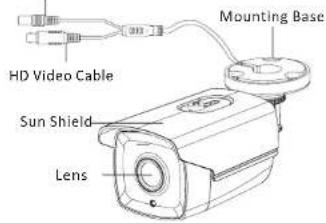
text_image
HD Video Cable Sun Shield Lens Mounting BaseFigure 1-1 Overview of Type I Camera
1.2.2 Overview of Type Camera
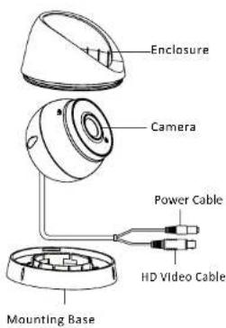
text_image
Enclosure Camera Power Cable HD Video Cable Mounting BaseFigure 1-2 Overview of Type II Camera
2 Installation
Before you start:
- Please make sure that the device in the package is in good condition and all the assembly parts are included.
- Make sure that all the related equipment is power-off during the installation.
- Check the specification of the products for the installation environment.
- Check whether the power supply is matched with your power output to avoid damage.
- Please make sure the wall is strong enough to withstand three times the weight of the camera and the mounting.
- If the wall is the cement wall, you need to insert expansion screws before you install the camera. If the wall is the wooden wall, you can use self-tapping screw to secure the camera.
- If the product does not function properly, please contact your dealer or the nearest service center. Do not disassemble the camera for repair or maintenance by yourself.
2.1 Installation of Type Cameral
Steps:
- Drill the screw holes in the ceiling according to the supplied drill template.
- Hammer the supplied plastic expansion bolt into the screw holes.

text_image
Drill Template All Screw Holes: for mounting baseFigure 2-1 Drill Template
- Route the cables to the cable hole and connect the corresponding power cable and video cable.
- Fix the camera to the ceiling with the supplied screws.
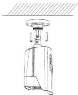
natural_image
Technical line drawing of a mechanical device with no visible text or symbols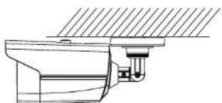
natural_image
Technical line drawing of a mechanical assembly or mounting bracket (no text or symbols)Figure 2-2 Fix the Camera to the Ceiling
- Adjust the surveillance angle.
1). Loosen No.3 adjusting screw to adjust the panning position 0 \~ 360 . ( ° ° )
2). Tighten No.3 adjusting screw
3). Loosen the No.2 adjusting screw to adjust the tilting position (0° \~ 90°).
4). Tighten No.2 adjusting screw.
5). Loosen No.1 adjusting screw to adjust the azimuth angle of the image (0° \~ 360°).
6). Tighten No.1 adjusting screw
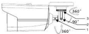
Figure 2-3 3-axis Adjustment
2.2 Installation of Type II Camera
Steps:
- Drill the screw holes and the cable hole on the ceiling according to the supplied drill template.
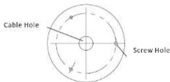
text_image
Cable Hole Screw HoleFigure 2-4 The Drill Template
- Fix the mounting base to the ceiling with the supplied screws.
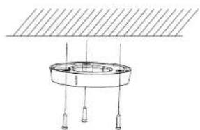
natural_image
Simple line drawing of a circular component with three vertical posts and a horizontal plane above (no text or symbols)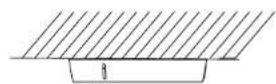
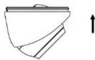
Figure 2-5 Fix the Mounting Base and Camera
- Route the cables to the cable hole and connect corresponding power cable and video cable.
- Secure the camera to the mounting base.
- Adjust the camera according to the figure below to get an optimum angle.
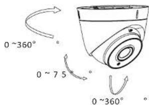
text_image
0 ~360° 0 ~ 75° 0 ~360°Figure 2-6 3-axis Adjustment