305101 - Autre appareil de cuisine Vimitex - Free user manual and instructions
Find the device manual for free 305101 Vimitex in PDF.

User questions about 305101 Vimitex
0 question about this device. Answer the ones you know or ask your own.
Ask a new question about this device
Download the instructions for your Autre appareil de cuisine in PDF format for free! Find your manual 305101 - Vimitex and take your electronic device back in hand. On this page are published all the documents necessary for the use of your device. 305101 by Vimitex.
USER MANUAL 305101 Vimitex
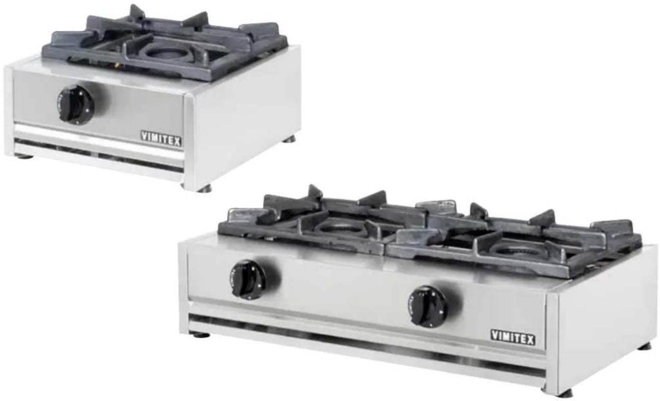
INSTRUCTIONS FOR INSTALLATION, USE & MAINTENANCE STOVE TOP Series 0200
MODELS: 0202(P), 0204(P), 0206(P), (305001-305101) 0201/K(P), (305002-305102) 0202/K(P), 0203/K(P) 202ST(P), 204ST(P), 206ST(P), 751ST(P), 752ST(P), 753ST(P), ST2(P), ST4(P), ST6(P) 204STV(P), 206STV(P), 204STVE(P), 206STVE(P), 206STVBE(P)
natural_image
Two VIMITEX gas stove units with black grilles and control knobs, shown from different angles (no text or symbols visible on the devices themselves)ADJUSTED FOR: (I3+) G-30/G31 28-30/37 mbar
ATTENTION: USE ONLY IN WELL VENTILATED PLACES
READ CAREFULLY & SAVE THIS INSTRUCTIONS MANUAL, BEFORE INSTALLATION & USE OF THE APPLIANCE
Directive 2009/142/EC
text_image
Diagram showing three mechanical components with numbered parts and directional arrows indicating motion or assembly.FIG. B
text_image
FIG. 2 (RUTTER 2017)FIG. C (BURNER 200E)

text_image
Technical diagram showing labeled components of a mechanical or electrical assembly with numbered parts and a dimension 'd' indicated.FIG. C
text_image
Diagram illustrating three steps of a mechanical or electrical operation with labeled components and directional arrowsFIG. D
text_image
1 2 3FIG. C1
Operating Instructions
Description STOVE TOP Fig. A
-
Body
-
Injector Cover
-
Grate
-
Drawer
-
Burner
-
Adjustable Feet
-
Thermomagnetic Valve
-
Thermocouples
-
Knobs
| TECHNICAL SPECIFICATIONS | ||||
| CATEGORIES: I2H, I2E, I2E+, I3B/P, I3+, II2H3+, II2H3B/P 50mbar, II2E+3+,II2E+3B/P, II2E3B/P | ||||
| COUNTRY CATEGORY GAS PRESSURE | ||||
| AT Austria | I2H G-20 20 mbar | |||
| " | I3B/P | G-30/G-31 | 50 | mbar |
| BE Belgium | I2E+ | G-20 | 20/25 | mbar |
| " | I3+ | G-30/G-31 | 28-30/37 | mbar |
| DK Denmark | I2H G-20 20 mbar | |||
| " | I3B/P | G-30/G-31 | 30 | mbar |
| FI Finland | I2H G-20 20 mbar | |||
| " | I3B/P | G-30/G-31 | 30 | mbar |
| FR France | I2E+ | G-20 | 20/25 | mbar |
| " | I3+ | G-30/G-31 | 28-30/37 | mbar |
| " | I3B/P | G-30/G-31 | 50 | mbar |
| DE Germany | I2E | G-20 20 mbar | ||
| " | I3B/P | G-30/G-31 | 50 | mbar |
| GR Greece | I2H G-20 20 mbar | |||
| " | I3+ | G-30/G-31 | 28-30/37 | mbar |
| IE Ireland | I2H G-20 20 mbar | |||
| " | I3+ | G-30/G-31 | 28-30/37 | mbar |
| IT Italy | I2H G-20 20 mbar | |||
| " | I3+ | G-30/G-31 | 28-30/37 | mbar |
| NL Netherlands | I3B/P | G-30/G-31 | 30 | mbar |
| PT Portugal | I2H G-20 20 mbar | |||
| " | I3+ | G-30/G-31 | 28-30/37 | mbar |
| ES Spain | I2H G-20 20 mbar | |||
| " | I3+ | G-30/G-31 | 28-30/37 | mbar |
| SE Sweden | I2H G-20 20 mbar | |||
| " | I3B/P | G-30/G-31 | 30 | mbar |
| GB United Kingdom | I2H G-20 20 mbar | |||
| " | I3+ | G-30/G-31 | 28-30/37 | mbar |
| Model | Dimensions cm | Burner Type | Pan Diameter mm | G20 20mbar 2^nd fam. H,E,E+ | G-25 25mbar 2^nd fam. L | G-30 28-30mbar 3^rd fam. 3+ | G-31 37mbar 3^rd fam. 3+ | G-30 50mbar 3^rd fam. B/P | G-31 50mbar 3^rd fam. B/P | ||||||
| -ΣQn-kW(Hi) | m^3/h | -ΣQn-kW(Hi) | m^3/h | -ΣQn-kW(Hi) | g/h | -ΣQn-kW(Hi) | g/h | -ΣQn-kW(Hi) | g/h | -ΣQn-kW(Hi) | g/h | ||||
| 0202(P) | 38x70x20 | 200 | 20-35 | 12.54 | 1.26 | 13.80 | 1090 | 12.60 | 982 | 13.28 | 1050 | 11.78 | 920 | ||
| 0204(P) | 71x70x20 | 200 | 20-35 | 25.08 | 2.52 | 27.60 | 2180 | 25.20 | 1964 | 26.56 | 2100 | 23.56 | 1840 | ||
| 0206(P) | 104x70x20 | 200 | 20-35 | 37.62 | 3.77 | 41.40 | 3270 | 37.80 | 2946 | 39.84 | 3140 | 35.34 | 2750 | ||
| 0201K(P) | 36,5x40x20 | 200 | 20-35 | 6.27 | 0.63 | 6.90 | 495 | 6.30 | 541 | 6.64 | 525 | 5.89 | 460 | ||
| 0202K(P) | 71x40x20 | 200 | 20-35 | 12.54 | 1.26 | 13.80 | 1090 | 12.60 | 982 | 13.28 | 1050 | 11.78 | 920 | ||
| 0203K(P) | 104x40x20 | 200 | 20-35 | 18.81 | 1.89 | 20.70 | 1635 | 18.90 | 1453 | 19.92 | 1570 | 17.67 | 1370 | ||
| 202ST(P) | 40x70x85/25 | 200 | 20-35 | 12.54 | 1.26 | 13.80 | 1090 | 12.60 | 982 | 13.28 | 1050 | 11.78 | 920 | ||
| 204ST(P) | 80x70x85/25 | 200 | 20-35 | 25.08 | 2.52 | 27.60 | 2180 | 25.20 | 1964 | 26.56 | 2100 | 23.56 | 1840 | ||
| 206ST(P) | 120x70x85/25 | 200 | 20-35 | 37.62 | 3.77 | 41.40 | 3270 | 37.80 | 2946 | 39.84 | 3140 | 35.34 | 2750 | ||
| 751ST(P) | 40x70x430 | 200 | 20-35 | 12.54 | 1.26 | 13.80 | 1090 | 12.60 | 982 | 13.28 | 1050 | 11.78 | 920 | ||
| 752ST(P) | 80x70x430 | 200 | 20-35 | 25.08 | 2.52 | 27.60 | 2180 | 25.20 | 1964 | 26.56 | 2100 | 23.56 | 1840 | ||
| 753ST(P) | 120x70x430 | 200 | 20-35 | 37.62 | 3.77 | 41.40 | 3270 | 37.80 | 2946 | 39.84 | 3140 | 35.34 | 2750 | ||
| ST2 | 34,5x80x24 | 200 | 20-35 | 12.54 | 1.26 | 13.80 | 1090 | 12.60 | 982 | 13.28 | 1050 | 11.78 | 920 | ||
| ST4 | 90x80x24 | 200 | 20-35 | 25.08 | 2.52 | 27.60 | 2180 | 25.20 | 1964 | 26.56 | 2100 | 23.56 | 1840 | ||
| ST6 | 134,5x80x24 | 200 | 20-35 | 37.62 | 3.77 | 41.40 | 3270 | 37.80 | 2946 | 39.84 | 3140 | 35.34 | 2750 | ||
| 204STV(P) | 80x70x98,5 | 200 | 20-35 | 33.35 | 3.32 | 35.20 | 2780 | 32.80 | 2556 | 34.36 | 2715 | 30.76 | 2391 | ||
| 206STV(P) | 120x70x98,5 | 200 | 20-35 | 45.89 | 4.57 | 49.00 | 3870 | 45.40 | 3538 | 47.64 | 3755 | 42.54 | 3311 | ||
| 204STVE(P) | 80x70x98,5 | 200E | 14-35 | 32.80 | 3.29 | 30.80 | 2430 | 30.80 | 2400 | 32.60 | 2572 | 30.40 | 2368 | ||
| 206STVE(P) | 120x70x98,5 | 200E | 14-35 | 45.20 | 4.53 | 42.40 | 3345 | 42.40 | 3303 | 45.00 | 3550 | 42.00 | 3272 | ||
| 206STVBE(P) | 91x80x96,5 | 200 | 20-35 | 45.89 | 4.57 | 49.00 | 3870 | 45.40 | 3538 | 47.64 | 3755 | 42.54 | 3311 | ||
| INJECTORS DIAMETER | Burner Type: | 200 | 200E | OVEN | |
| Gas 2nd fam. H,E,E+ | G-20 | 20 mbar: | 1.90 mm | 1.90 mm | 2.20mm |
| Gas 3rd fam. 3+ | G-30/G-31 | 28-30/37 mbar: | 1.25 mm | 1.25 mm | 1.45mm |
| Gas 3rd fam. B/P | G-30 | 50 mbar: | 1.15 mm | 1.15 mm | 1.35mm |
| Gas 3rd fam. B/P | G-31 | 50 mbar: | 1.15 mm | 1.15 mm | 1.35mm |
| Qmin | |||||
| Gas 2nd fam. H,E,E+ | G-20 | 20 mbar: | 1.7 kW | 2.4 kW | - |
| Gas 3rd fam. 3+ | G-30 | 28-30 mbar: | 1.7 kW | 2.4 kW | - |
| Gas 3rd fam. 3+ | G-31 | 37 mbar: | 1.7 kW | 2.4 kW | - |
| Gas 3rd fam. B/P | G-30 | 50 mbar: | 1.7 kW | 2.4 kW | - |
| Gas 3rd fam. B/P | G-31 | 50 mbar: | 1.7 kW | 1.5 kW | - |
OVEN PRIMARY AIR REGULATOR: THIS APPLIANCE DOESN'T NEED REGULATING THE PRIMARY AIR AFTER CHANGING THE GAS YOU USE.
TYPE: A1
A. INSTALLATION
A.1. Warning
WARNING: THIS APPLIANCE MUST BE INSTALLED BY A SPECIALIST TECHNICIAN ACCORDING TO THE LAWS AND REGULATIONS IN FORCE IN THE COUNTRY OF DESTINATION, IN WHICH THE APPLIANCE WILL BE USED
WARNING: THIS APPLIANCE MUST BE INSTALLED ONLY IN WELL AND SUFFICIENT VENTILATED SPACES TO PREVENT THE OCCURRENCE OF UNACCEPTABLE CONCENTRATIONS OF SUBSTANCES HARMFUL TO HEALTH
THERE A SERIOUS HEALTH RISK IF THIS APPLIANCE IS USED IN PLACES WITH INADEQUATE VENTILATION.
FIRE DANGER – THE AREA AROUND THE APPLIANCE MUST BE FREE AND CLEAN FROM FUEL.
For technical support address to the manufacture authorized service.
Ask for the genuine spare parts.
- The appliance must only be used by trained staff and must be supervised at all times when in use.
- Switch off the appliance if it breaks down or malfunctions.
- Do not use products containing chlorine (bleach, hydrochloric acid etc.) even diluted, to clean steel surfaces.
- Do not leave dirt, fat, food or other products to dry on the appliance.
- This appliance is intended for industrial use only and is specifically designed to cook food. Any other use of the appliance is deemed improper.
- Only contact the technical service centre authorized by the manufacturer for repairs and only use original spare parts. Failure to comply with the above requirement may jeopardize the safety of the appliance and render the guarantee null and void.
- Do not use corrosive substances (i.e. muriatic acid) to clean the floor under the appliance.
- Do not wash the appliance with water jets
NOT FOLLOWING THE ABOVE INSTRUCTIONS MIGHT AFFECT THE SECURITY OF THE APPLIANCE. NOT FOLLOWING THE ABOVE INSTRUCTIONS CAN CAUSE THE GUARANTEE'S DEDUCTION.
A.2. Safety Rules for Installation
This appliance cannot be connected to a duct for removing the products of combustion.
Particular care must be taken with the ventilation systems you use.
The installation, connection and maintenance must be undertaken only by a specialist technician, taking into account all the present instructions, as well as the remaining provisions concerning the site of installation:
- Examine the packaging before and after the uploading.
- An adequate flow of air in and out of the area is needed
- A window, opening to at least 0.40m^2 is required
- The installation, use and maintenance of this appliance by children is strictly prohibited. Keep children and curious onlookers away when the appliance is in operation.
- The appliance must be installed on a horizontal surface, with a constant heat resistance of at least 90^ C. All flammable surfaces are prohibited.
- A space of 0.20m must be left around the appliance for ventilation.
- This appliance is not suitable for built –in installation.
- Carefully remove the protective film from the external panels to avoid leaving any trace of glue.
- Use a suitable diluents to remove any glue residue.
- Is strictly forbidden to place objects or food on the top of the appliance.
- Don't hang anything over the appliance closer than 1,5m. Leave always the space of 1,5m empty over the appliance because the heat from the exhaust duct is very high.
- Do not place anything in front of the appliance at a distance of less than 1.5 meter, because the temperature in front of the open door is very high.
- Installation and use of this appliance in basement areas is prohibited.
A.3. Connection
The appliance may be connected in three ways, depending on the type of gas to be used. The connection point (4), Figure C, between the appliance and the gas supply is situated at the bottom (or the back) of the appliance.
A rapid-action gas shut-off cock must be fitted upstream of each appliance in an easily accessible position.
Once the appliance has been installed, check for gas leaks at connection points using a soapy water solution.
ATTENTION: In case of use for the gas supply connection of the appliance a flexible tube or hose, this shall comply with the national requirements and shall be periodically inspected and replaced as necessary.
This appliance must be connected for gas supply only with approved flexible hoses or tubes. Their length should not exceed 1.5m and it is forbidden to twist them.
A.3.1 Use of the Appliance with Butane & Propane
Butane: Use an approved low pressure regulator 28 – 30mbar
Propane: Use an approved low pressure regulator 37mbar
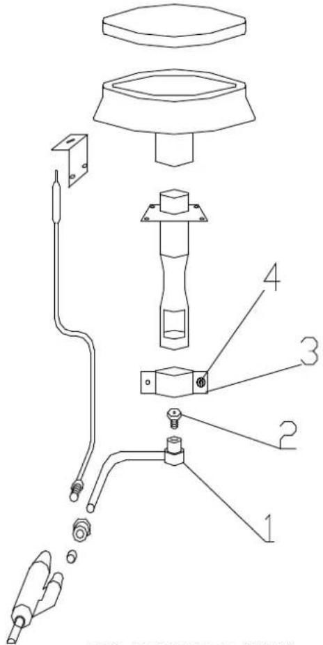
In this case, you may use the connection nozzle (1), Figure B, which accompanies the appliance, to connect it with a flexible pipe.
Screw the nozzle on the bottom (or the back) of the appliance, to the gas connection port (4), with a diameter of 16 mm (3/8).
This pipe must be approved for this use.
You must check the date of replacement of the pipe. You must install it in such a way that it is visible along the whole length (from the appliance to the supply tap or to the bottle).
The connections must be checked for leaks in order to avoid gas escaping, with the help of soapy water.
To do so: open the bottle or the supply-tap, to allow the gas to circulate, and ensure that the connection is correct by checking for air bubbles in the soapy water spread over the connections.
DANGER: THE USE OF A FLAME TO CHECK FOR LEAKS AT CONNECTION POINTS IS STRICTLY FORBIDDEN.
A.3.2 Use of the Appliance with Natural Gas
Connection may be made with the help of the nozzle (2), Figure B, when a flexible pipe is to be used, following the instructions on the previous paragraph with regard to connection and checking for leaks.
If you wish to make a permanent, fixed connection with a hard pipe screwed into position, it will be necessary to use the nozzle (3), Figure B. This is the recommended type of connection.
DANGER: THE USE OF A FLAME TO CHECK FOR LEAKS AT CONNECTION POINTS IS STRICTLY FORBIDDEN.
A.3.3 Use of the Appliance with Propane & Butane 50 mbar
Butane: Use an approved low pressure regulator 50mbar
Propane: Use an approved low pressure regulator 50mbar
Connection may be made with the help of the nozzle (1), Figure B, when a flexible pipe is to be used, following the instructions on paragraph 3.1, with regard to connection instructions and checking for leaks.
If you wish to make a permanent, fixed connection with a hard pipe screwed into position, it will be necessary to use the nozzle (3), Figure B. This is the recommended type of connection.
DANGER: THE USE OF A FLAME TO CHECK FOR LEAKS AT CONNECTION POINTS IS STRICTLY FORBIDDEN.
A.4. Adaptation for Gas Change
All appliances, on delivery, are factory adjusted for use with Propane 37 mbar (G31) or Butane 28-30mbar (G30). However, it is necessary to determine whether the low pressure regulator you are using is approved for 37 mbar for Propane or 28-30mbar for Butane, respectively.
In case the appliance is to be used with natural gas, or with Propane and Butane at a pressure of 50 mbar, the following adjustments must be made after installation, only by a specialist technician, as explained on paragraphs 4.1, 4.2, 4.3 and 4.4:
- change of injectors
- change of injector of the Oven pilot burner
- adjustment of the flow of air into the burner
- adjustment of the thermomagnetic gas valve of each burner to the position 'minimum' (▲, small flame)
After the change of the injector and the air regulation, in order to obtain the gas changes it's necessary to put a mark on the data plate which is placed on the body of the appliance to indicate the new gas regulation.
A.4.1 Change of Injectors
The following procedure must be done having the gas supply closed:
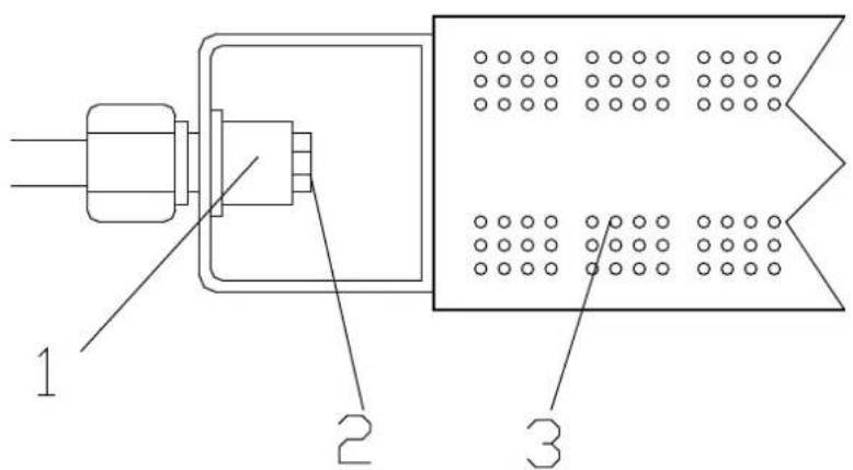
To change the injectors on the top burners, you must first remove the grates (2) and unscrew the injector cover (5) of the appliance Fig. A. You must remove the burners by unscrewing the two screws under the burner that keep them into position. The injectors may then be changed. At the edge of each thermomagnetic gas valve (1) Figure C, are the injectors (2). With a number 7 spanner, or a special screwdriver number 7, unscrew the injectors and replace them with the injectors you will find in the appliance packaging, either those marked 'Natural Gas' or those marked 'I3 B/P: 50 mbar', depending on the gas you are using.
To change the injectors on the oven burner:
- Open the oven door, remove the griddles and the metallic surface situated on the bottom of the oven chamber by pulling up using the hole at the front part.
- By using a screwdriver, loosen up the two screws and the remove the cover of the burner.
- With a number 13 spanner, unscrew the injector (2) Fig C' and replace it with the injector you will find in the appliance packaging, either this marked 'Natural Gas' or this marked 'I3 B/P: 50 mbar', depending on the gas you are using.
A.4.2 Change of the injector of the Oven pilot Burner
The following procedure must be done having the gas supply closed.
After changing the burner injector you have to change also the pilot burner injector which are located next to the main burners.
By using a screwdriver, loosen up the two screws and the remove the cover of the burner of the appliance according to the paragraph A.4.1
With No 11 unscrew the back-end cover of the pilot (12) fig. E and by using a screwdriver replace the injector inside the body of the pilot.
Place again the cover with a spanner no 11 and put all the parts on place.
WARNING: It is strictly forbidden to modify the entrance of the combustion air differently from the indicated in this Instruction Manual as well as the combustion products evacuation.
A.4.3 Adjustment of the Flow of Primary Air into the Burner
The following procedure is followed, having the gas supply closed. The flow of air into the top burners must be adjusted using the ring (3), Figure C, sited on the burner and supported with a screw (4). Loosen the screw (4), place the ring in a position such that the distance d=8 mm, for Natural Gas and d=11 mm for the 'I3 B/P: 50 mbar'.
Tighten the screw (4) again so that the ring (3) is properly secured on the burner.
Put the burners back into position, taking care to position them correctly and replace the screws that have been removed. Replace the injector cover and the grates of the appliance.
WARNING: It is strictly forbidden to modify the entrance of the combustion air differently from the indicated in this Instruction Manual as well as the combustion products evacuation.
A.4.4 Adjustment of the Thermomagnetic Gas Valve of each Top Burner to the 'Minimum' position (↓, small flame)
The following procedure is followed after the procedures referred to on paragraphs 4.1 and 4.3 are completed. All thermomagnetic gas valves of the top burners must be adjusted. After the appliance has been installed and connected according to the above instructions, light the burner according to the instructions on paragraph B.2 Ignition.
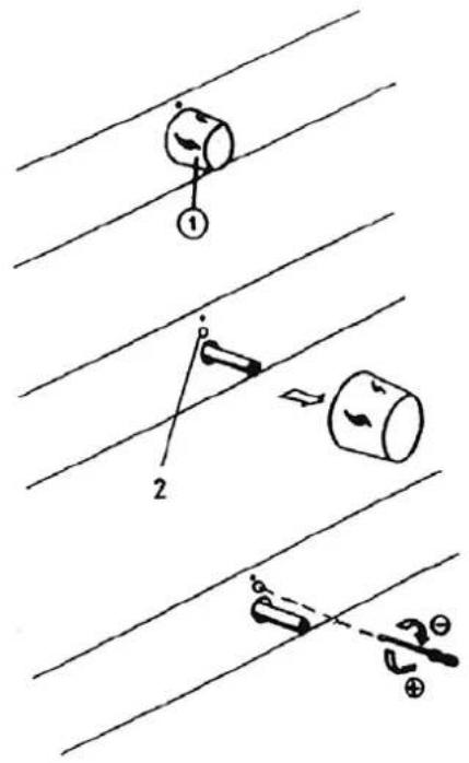
Turn the thermomagnetic valve knobs (1), Figure D, to the 'Minimum' position (♦, small flame) and then pull them out. The adjustment screw is sited in the hole (2), right above the thermomagnetic gas valve. Using a very small screwdriver, 2 mm wide, adjust the intensity of each burner. Do not forget to keep all the gas valves at the minimum (♦, small flame) position. Turning the screwdriver to the left, the flame gets larger, and to the right, the flame gets smaller, as shown in Figure D. The appliance is properly adjusted when you see a small, steady, blue-colored flame on the burner. Replace the valve knobs (1) and then turn the appliance off, by turning the knobs back to the position (●).
A.5 EQUIPOTENTIAL TERMINAL:
This terminal at the bottom or the back of the appliance is only for connecting two or more appliances together with an equipotential node.
B. USE
B.1. Safety Rules for Use
WARNING: THIS APPLIANCE MUST BE USED ONLY IN WELL VENTILATED PLACES
WARNING: IT'S STRICTLY FORBIDDEN TO OPEN THE DOOR WHEN THE OVEN IS HOT. THERE IS DANGER OF BURN ON YOUR FACE AND HANDS, BECAUSE OF THE HOT AIR THAT GOES OUT THE MOMENT OF THE DOOR OPENING.
WARNING: IT IS STRICTLY FORBIDDEN TO PLACE ANY COMBUSTIBLE MATERIAL IN FRONT OF THE APPLIANCE IN A DISTANCE LOWER THAN 2,00 METERS, OR ABOVE OF IT.
WARNING: TO REDUCE CONSUMPTION OF GAS, DO NOT USE THE APPLIANCE EMPTY OR IN CONDITION THAT COMPROMISE OPTIMAL EFFICIENCY (E.G. WITH THE DOOR OR LIDS OPEN ETC.) WHENEVER POSSIBLE, PREHEAT ONLY BEFORE USE.
WARNING: THIS APPLIANCE IS DESTINED FOR PROFESSIONAL USE ONLY AND MUST BE USED BY SKILLED PERSONNEL
WARNING: IT'S STRICTLY FORBIDDEN TO CLOSE THE EXHAUST DUCT ON THE TOP OF THE APPLIANCE
WARNING: KEEP EMPTY THE FAT COLLECTOR OR ANY RECEPTACLE PAN YOU MIGHT USE FOR THE COLLECTION OF THE FATS ON THE LOWER PART OF THE APPLIANCE IN ORDER TO AVOID RISK OF FIRE, DUE TO OVERHEATING.
WARNING: KEEP CLEAN THE COOKING CABINET AND SPECIALLY THE BOTTOM, OF THE APPLIANCE, WHERE FAT MAY ACCUMULATE FREQUENTLY, IN ORDER TO AVOID RISK OF FIRE, DUE TO OVERHEATING.
- The appliance must be used exclusively for the intended purpose, for cook food and boiling food by casseroles, pans, frying pans. Any other use is considered improper.
Placing food directly on the appliance is strictly forbidden.
Installation, use and maintenance of this appliance by children is strictly prohibited. Keep children and curious onlookers away while the appliance is in operation.
Clean the parts of the appliance where fat may accumulate, frequently, in order to avoid fat inflammation, due to overheating.
Pouring liquids (e.g. fat, water, sauces etc.) on the appliance is strictly forbidden.
Frequently empty the fat-collector drawer.
The minimum diameter of the casseroles, pans, frying pans etc that can be used for cooking is 140 mm and the maximum diameter is 350mm depending of the model. See Table on page 5.
B.2. Ignition
Having connected the appliance according to the above instructions, open the gas supply to the appliance.
TOP BURNERS: Each of the top burners (3) Figure A, has its own thermomagnetic valve knob (4), which adjusts its intensity. The appliance is delivered with the thermomagnetic valve knobs of the burners closed, that is to the (●) position. When you wish to start the appliance, with one hand press down and turn the thermomagnetic valve knob (4), to the left, to the position (*). With the other hand approach a lit conventional lighter to the burner, until the burner is ignited.
Continue holding the thermomagnetic valve knob (4) pressed down for about 5" seconds. In case the burner fails to light, repeat the above procedure.
You can now ignite the other burners, by repeating the above procedure.
Adjust the level of each burner to your preference, slowly turning the valve knobs (4) towards the 'minimum' position with the symbol ( small flame).
The high or low temperature of the burners is achieved by turning the thermomagnetic valve knobs either to the left or to the right.
B.3. Turning Off
To turn the top burners off, turn all the thermomagnetic valve knobs(4) to the position (●), so that the burners go out, too.
To turn the oven off, turn the valve knob (7) to the (*) position, so that the burner shut down.
To turn the pilot burner off, you must press and turn knob (7) to the (●) position (or-depend to the valve- you must push the button (8) of thermostatic valve with the symbol (●).
The appliance is then turned off.
B.5. Ventilation
During cooking, smoke and steam is given off. Therefore, the site where the appliance is used must be properly ventilated by opening a window or with the help of a special ventilation mechanism (extractor fan).
Warning: Care must be taken never to cover the oven exhaust grid (2) Figure A.
C. CLEANING & MAINTENANCE
REGULAR CLEANING HELPS THE PROPER AND BETTER OPERATION OF THE APPLIANCE.
WARNING: KEEP CLEAN ALL THE PARTS OF THE APPLIANCE AND THE COOKING CABINET - SPECIALLY THE BOTTOM - OF THE APPLIANCE, WHERE FAT MAY ACCUMULATE FREQUENTLY, IN ORDER TO AVOID RISK OF FIRE, DUE TO OVERHEATING.
During cleaning, the appliance as well as the gas supply should always be turned off.
- Do not wash the appliance with water jets.
- Wait for the oven chamber to cool
- Clean stainless steel surfaces with warm water and soap, rinse and dry thoroughly.
- Our appliances are manufactured using metals (stainless steel, mild steel, zinc plated sheet metal etc) and can therefore be recycled in conventional waste recovery sites in compliance with current standards in the country of installation.
- To minimize the emission of pollutants into the environment, we recommend cleaning the appliance externally and, where necessary, internally with products which are at least 90% biodegradable.
- You can easily remove the grates and the fat-collector drawer for cleaning.
- Remove the cabinet Griddles and large baking Pan and all their accessories for cleaning, by simply drag them out.
- You can wash them with brand-name cleaning products, approved of use on surfaces that comes in touch with food.
- Always rinse with plenty of water and dry before use.
Replace correctly all the above accessories that were removed for cleaning.
The appliance is ready to be used again.
D. LIST OF SPARE PARTS & GREASING (Fig. A & E)
Thermomagnetic gas valve (4, Fig A): Has to be changed when you notice a malfunction on the rotation of the axe (stiff, bent, ect.) or when you notice leak of gas near the axe, or the body of the valve.
Thermostatic gas valve (1, Fig E): It has to be changed when you notice that it doesn't regulated correctly the temperature oven, or when you notice a gas leak near the axe or the body of the valve.
Magnet Unit: It is placed inside the thermostatic gas valve. It has to be changed when you notice that it is not possible for the pilot to stay lit after you light it up, but only if you are sure that the thermocouple is working properly and is well screwed.
Thermocouple (9, Fig E): Has to be changed when you notice that it is not possible for the burner or the pilot to stay lit after you light it up.
The grades(2, Fig A): They have to be changed when they are deformed or broken, so the cooking utensils (casseroles or pans) are stable.
The burner (5, Fig E): It has to be changed when you notice that some of the holes have become bigger or deformed, the surface is damaged, the whole burner is broken or it is very dirty.
The high voltage cable (11, Fig E) of the spark plug: It has to be changed when you notice that it is not possible to create a spark when you press the piezoelectric igniter, although the spark plug is working properly.
The pilot (12, Fig E): It has to be changed when you notice that it is not possible to be lit, or the flame is not correct (the color must be blue), because of the fats.
Piezoelectric igniter (13, Fig E): It has to be changed when you press it and it is not possible to create a spark, although the spark plug and the high tension cable are correct.
The spark plug (16, Fig E): It has to be changed when you notice that it is not possible to create a spark when you press the piezoelectric igniter, although the connection of the cable is correct.
- Door Isolation Rubber: It must be replaced when it is deformed, cut or destroyed resulting in incorrect closing of the door and, therefore, leakage of temperature.
- Removable griddles-pans: They Must be replaced when are deformed, broken or very dirty because they can be dangerous for the food and for the user.
ATTENTION: The above cases should be handled only by specialized technicians.
ATTENTION: It's strictly forbidden to touch, to regulate or repair the internal part of the thermomagnetic gas valve, the gas tubes and the burners that is located inside the metallic body (1), under the grades (2) of the machine Fig A, or under the cooking cabinet of the oven.
INSPECTION: The gas supply tubing or hose used for the connection of the appliance, shall comply with the national requirements in force and it shall be periodically inspected every month, for gas leaks and their good condition and be replaced if necessary.
INSPECTION: The function of the machine and the good condition of all the parts must be inspected every month. Specially, the blue color of the flame of the top burners must be inspected every day. The stability of the casseroles and the pans on the grades must be inspected every month. In case of deformation the grates must be replaced. The smooth rotation of the knobs of the valves must be inspected daily and to be replaced in case of malfunction or gas leak. Also, the good condition of the inside surface of the cooking cabinet of the oven and the griddle gliders, must be inspected every day if they are cleaned, broken or damaged.
INSPECTION & GREASING: The thermomagnetic gas valve must be inspected for inside greasing, once per year but only by specialized technicians.
BE IN CONTACT WITH VIMITEX FOR DETAILED INSTRUCTION.
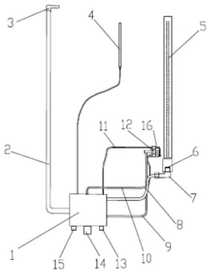
text_image
Technical diagram of a mechanical device with numbered components for identificationE. ASSEMBLING – DISASSEMBLING SPARE PARTS
The following procedure is followed having the gas supply closed.
To change the thermocouple, gas tap, burner or the injector of the oven you must first remove the bottom of the cooking cabinet (11) of the appliance (1) Figure A-Oven. Afterwards, you unscrew the 4 screws that holds the cover on the left external side panel, that helps you to have an easier access on the valve and the tubing.
For the changes you can follow the instructions of the chapter A4.
To replace a burner (5), Fig. D, you must unscrew the two screws that hold it.
After the changes, you place back the cover on the left external side panel (1) Figure A and afterwards the bottom of the cooking cabinet (11) in its place.
The above cases must be undertaken only by a specialist technician, taking into account all the present instructions.