DT-400 - Projector SHARP - Free user manual and instructions
Find the device manual for free DT-400 SHARP in PDF.

User questions about DT-400 SHARP
0 question about this device. Answer the ones you know or ask your own.
Ask a new question about this device
Download the instructions for your Projector in PDF format for free! Find your manual DT-400 - SHARP and take your electronic device back in hand. On this page are published all the documents necessary for the use of your device. DT-400 by SHARP.
USER MANUAL DT-400 SHARP
For your assistance in reporting the loss or theft of your Projector, please record the Serial Number located on the bottom of the projector and retain this information. Before recycling the packaging, please ensure that you have checked the contents of the carton thoroughly against the list of "Supplied accessories" on page 5.
Model No.: DT-400
Serial No.:
There are two important reasons for prompt warranty registration of your new SHARP Projector, using the REGISTRATION CARD packed with the projector.
1. WARRANTY
This is to assure that you immediately receive the full benefit of the parts, service and labor warranty applicable to your purchase.
2. CONSUMER PRODUCT SAFETY ACT
To ensure that you will promptly receive any safety notification of inspection, modification, or recall that SHARP may be required to give under the 1972 Consumer Product Safety Act, PLEASE READ CAREFULLY THE IMPORTANT "LIMITED WARRANTY" CLAUSE. [U.S.A. ONLY]
WARNING:
High brightness light source. Do not stare into the beam of light, or view directly. Be especially careful that children do not stare directly into the beam of light.
WARNING: To reduce the risk of fire or electric shock, do not expose this product to rain or moisture.
See bottom of projector.

CAUTION
RISK OF ELECTRIC SHOCK. DO NOT REMOVE SCREWS EXCEPT SPECIFIED USER SERVICE SCREW.

CAUTION: TO REDUCE THE RISK OF ELECTRIC SHOCK, DO NOT REMOVE COVER. NO USER-SERVICEABLE PARTS EXCEPT LAMP UNIT. REFER SERVICING TO QUALIFIED SERVICE PERSONNEL.

The lightning flash with arrowhead symbol, within an equilateral triangle, is intended to alert the user to the presence of uninsulated “dangerous voltage” within the product’s enclosure that may be of sufficient magnitude to constitute a risk or electric shock to persons.

The exclamation point within a triangle is intended to alert the user to the presence of important operating and maintenance (servicing) instructions in the literature accompanying the product.
WARNING:
FCC Regulations state that any unauthorized changes or modifications to this equipment not expressly approved by the manufacturer could void the user's authority to operate this equipment. U.S.A. ONLY
INFORMATION
This equipment has been tested and found to comply with the limits for a Class B digital device, pursuant to Part 15 of the FCC Rules. These limits are designed to provide reasonable protection against harmful interference in a residential installation. This equipment generates, uses, and can radiate radio frequency energy and, if not installed and used in accordance with the operation manual, may cause harmful interference to radio communications. However, there is no guarantee that interference will not occur in a particular installation. If this equipment does cause harmful interference to radio or television reception, which can be determined by turning the equipment off and on, the user is encouraged to try to correct the interference by one or more of the following measures:
- Reorient or relocate the receiving antenna.
- Increase the separation between the equipment and the receiver.
- Connect the equipment into an outlet on a circuit different from that to which the receiver is connected.
- Consult the dealer or an experienced radio/TV technician for help.
U.S.A. ONLY
PRODUCT DISPOSAL
This projector utilises tin-lead solder, and a pressurised lamp containing a small amount of mercury. Disposal of these materials may be regulated due to environmental considerations. For disposal or recycling information, please contact your local authorities or, if you are located in the United States of America, the Electronic Industries Alliance: www.eiae.org.
Declaration of Conformity
SHARP PROJECTOR, MODEL DT-400
This device complies with Part 15 of the FCC rules. Operation is subject to the following conditions: (1) This device may not cause harmful interference, and (2) this device must accept any interference received, including interference that may cause undesired operation.
Responsible Party:
SHARP ELECTRONICS CORPORATION
Sharp Plaza, Mahwah, New Jersey 07430
TEL: 1-800-BE-SHARP (1-800-237-4277)
U.S.A. ONLY
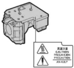
Caution Concerning Lamp Replacement
See "Replacing the Lamp" on page 56.
natural_image
Technical diagram of a mechanical or electronic component with no visible text, numbers, or symbols
LAMP REPLACEMENT WARNING :
TURN OFF THE LAMP AND DISCONNECT
POWER CORD BEFORE OPENING THIS
COVER. HOT SURFACE INSIDE
ALLOW 1 HOUR TO COOL BEFORE REPLACING THE LAMP.
REPLACE WITH SAME SHARP LAMP UNIT MODEL
AN-K2LP ONLY
HIGH PRESSURE LAMP : BISK OF EXPLOSION
POTENTIAL HAZARD OF GLASS PARTICLES IF LAMP HAS
RUPTURED. HANDLE WITH CARE. SEE OPERATION MANUAL.
SERVICEMAN-WARNING: USE RADIATION EYE AND
SKIN PROTECTION DURING SERVICING.

AVERTISSEMENT CONCERNANT LE
REEMPLACEMENT DE LA LAMPE :
ETEINDRE LA LAMPE ET DEBRANCHER LE CORDON
D'ALIMENTATION AVANT D'OUVRIR LE COUVERCLE
L'INTERIEUR DU BOITIER ETANT EXTREMEMENT CHAUD,
ATTENDRE 1 HEURE AVANT DE PROCEDER AU
REEMPLACEMENT DE LA LAMPE. NE REMPLACER QUE
PAR UNE LAMPE SHARP DE MODELE AN-K2LP.
LAMPE A HAUTE PRESSION : RISQUE
D'EXPLOSION. DANGER POTENTIEL DE PARTICULES DE
VERRE EN CAS D'ECLATEMENT DE LA LAMPE
A MANIPULER AVEC PRECAUTION.
SE REPORTER AU MODE D'EMPLOI
AVERTISSEMENT - REPARATEUR : SE PROTEGER LES
YEUX ET LA PEAU DES RADIATIONS LORS DES REPARATIONS
WARNING:
The cooling fan in this projector continues to run for about 90 seconds after the projector enters the standby mode. During normal operation, when putting the projector into standby mode always use the STANDBY button on the projector or on the remote control. Ensure the cooling fan has stopped before disconnecting the power cord. DURING NORMAL OPERATION, NEVER TURN THE PROJECTOR OFF BY DISCONNECTING THE POWER CORD. FAILURE TO OBSERVE THIS WILL RESULT IN PREMATURE LAMP FAILURE.
WARNING:
Some IC chips in this product include confidential and/or trade secret property belonging to Texas Instruments. Therefore you may not copy, modify, adapt, translate, distribute, reverse engineer, reverse assemble or discompile the contents thereof.
This SHARP projector uses a DMD panel. This very sophisticated panel contains 921,600 pixels micromirrors. As with any high technology electronic equipment such as large screen TVs, video systems and video cameras, there are certain acceptable tolerances that the equipment must conform to.
This unit has some inactive pixels within acceptable tolerances which may result in inactive dots on the picture screen. This will not affect the picture quality or the life expectancy of the unit.
- DLP ^TM (Digital Light Processing) and DMD ^TM (Digital Micromirror Device) are trademarks of Texas Instruments, Inc.
- Microsoft ^® and Windows ^® are registered trademarks of Microsoft Corporation in the United States and/or other countries.
• PC/AT is a registered trademark of International Business Machines Corporation in the United States. - Macintosh ^® is a registered trademark of Apple Computer, Inc. in the United States and/or other countries.
- All other company or product names are trademarks or registered trademarks of their respective companies.
Contents
Preparing
Introduction
Contents...... 4
Accessories 5
IMPORTANT SAFEGUARDS 6
Part Names and Functions ...... 9
Using the Remote Control 13
Usable Range 13
Inserting the Batteries 13
Quick Start
Quick Start 14
Setup
Setting Up the Projector 16
Setting Up the Projector 16
Screen Size and Projection Distance 17
Projecting a Reversed Image 18
Connections
Connections 19
INPUT Terminals and Connectable Main Equipment 19
Samples of Cables for Connection 20
Connecting to Video Equipment 21
Connecting to a Computer 25
Using
Basic Operation
Turning the Projector On/Off.... 27
Image Projection 29
Switching the INPUT Mode 29
Adjusting the Focus 30
Adjusting the Projected Image Size 30
Using the Adjustment Feet 31
Keystone Correction 32
Placement of the Projected Image Using the Keystone Correction 33
Selecting the Picture Mode 34
Switching the High Brightness / High Contrast Mode 34
Adjusting the Picture Aspect Ratio 34
Useful Features
Menu Items 36
Using the Menu Screen 38
Menu Selections (Adjustments) 38
Menu Selections (Settings) 40
Picture Adjustment ("Picture" menu) ..... 42
Adjusting the Image 42
Adjusting the Color Temperature 42
Gamma Correction Function 43
Emphasising the Contrast 43
Picture Mode Function.... 44
Switching the High Brightness/High Contrast Mode 44
Computer Image Adjustment
("Fine Sync" menu) 45
Adjusting the Computer Image 45
Special Modes Setting 45
Auto Sync Adjustment 46
Checking the Input Signal 46
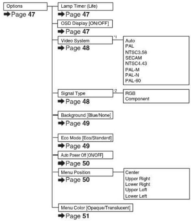
Using the "Options" Menu 47
Checking the Lamp Life Status 47
Setting On-screen Display 47
Setting the Video System.... 48
Signal Type Setting 48
Selecting a Background Image 49
Eco Mode 49
Auto Power Off Function 50
Selecting the Menu Screen Position 50
Selecting the Menu Color 51
Selecting the On-screen Display
Language and the Projection Mode ..... 52
Selecting the On-screen Display Language ..... 52
Setting the Projection Mode 52
Reference
Appendix
Maintenance 53
Maintenance Indicators 54
Regarding the Lamp 56
Lamp 56
Caution Concerning the Lamp 56
Replacing the Lamp 56
Removing and Installing the Lamp Unit 57
Resetting the Lamp Timer 58
Connecting Pin Assignments 59
Computer Compatibility Chart 60
Troubleshooting 61
Service Information (For the U.S.) 61
Specifications 62
Dimensions 63
Glossary 64
Index 65
CONSUMER LIMITED WARRANTY
(VALID IN USA ONLY) 66
LIMITED WARRANTY
(VALID IN CANADA ONLY) 67
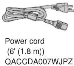
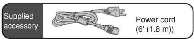
Supplied accessories
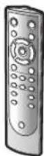
Remote control RRMCGA334WJSA
Lens cap (attached) PCAPHA021WJSA
Operation manual TINS-B532WJZZ
Optional accessories
■3 RCA to 15-pin D-sub cable (9'10" (3.0 m)) AN-C3CP
■DVI to 15-pin D-sub adaptor (7.9" (20 cm)) AN-A1DV
■DVI cable (9'10" (3.0 m)) AN-C3DV
■Lamp unit AN-K2LP

Note
- Some of the optional accessories may not be available depending on the region. Please check with your nearest Sharp Authorized Service Center or Dealer.
Marks Used in This Operation Manual

Info ......Indicates safeguards when using the projector.

Note ......Indicates additional information for setting up and operating the projector.
- In this operation manual, the illustration and the screen display are simplified for explanation, and may differ slightly from actual display.
CAUTION: Please read all of these instructions before you operate this product and save these instructions for later use.
Electrical energy can perform many useful functions. This product has been engineered and manufactured to assure your personal safety. BUT IMPROPER USE CAN RESULT IN POTENTIAL ELECTRICAL SHOCK OR FIRE HAZARDS. In order not to defeat the safeguards incorporated in this product, observe the following basic rules for its installation, use and servicing.
1. Read Instructions
All the safety and operating instructions should be read before the product is operated.
2. Retain Instructions
The safety and operating instructions should be retained for future reference.
3. Heed Warnings
All warnings on the product and in the operating instructions should be adhered to.
4. Follow Instructions
All operating and use instructions should be followed.
5. Cleaning
Unplug this product from the wall outlet before cleaning. Do not use liquid cleaners or aerosol cleaners. Use a damp cloth for cleaning.
6. Attachments
Do not use attachments not recommended by the product manufacturer as they may cause hazards.
7. Water and Moisture
Do not use this product near water-for example, near a bath tub, wash bowl, kitchen sink, or laundry tub; in a wet basement; or near a swimming pool; and the like.
8. Accessories
Do not place this product on an unstable cart, stand, tripod, bracket, or table. The product may fall, causing serious injury to a child or adult, and serious damage to the product. Use only with a cart, stand, tripod, bracket, or table recommended by the manufacturer, or sold with the product. Any mounting of the product should follow the manufacturer's instructions, and should use a mounting accessory recommended by the manufacturer.
9. Transportation
A product and cart combination should be moved with care. Quick stops, excessive force, and uneven surfaces may cause the product and cart combination to overturn.

10. Ventilation
Slots and openings in the cabinet are provided for ventilation to ensure reliable operation of the product and to protect it from overheating, and these openings must not be blocked or covered. The openings should never be blocked by placing the product on a bed, sofa, rug, or other similar surface. This product should not be placed in a built-in installation such as a bookcase or rack unless proper ventilation is provided or the manufacturer's instructions have been adhered to.
11. Power Sources
This product should be operated only from the type of power source indicated on the marking label. If you are not sure of the type of power supply to your home, consult your product dealer or local power company. For products intended to operate from battery power, or other sources, refer to the operating instructions.
12. Grounding or Polarization
This product is provided with one of the following types of plugs. If the plug should fail to fit into the power outlet, please contact your electrician.
Do not defeat the safety purpose of the plug.
a. Two-wire type (mains) plug
b. Three-wire grounding type (mains) plug with a grounding terminal.
This plug will only fit into a grounding type power outlet.
13. Power-Cord Protection
Power-supply cords should be routed so that they are not likely to be walked on or pinched by items placed upon or against them, paying particular attention to cords at plugs, convenience receptacles, and the point where they exit from the product.
14. Lightning
For added protection for this product during a lightning storm, or when it is left unattended and unused for long periods of time, unplug it from the wall outlet and disconnect the cable system. This will prevent damage to the product due to lightning and power-line surges.
15. Overloading
Do not overload wall outlets, extension cords, or integral convenience receptacles as this can result in a risk of fire or electric shock.
16. Object and Liquid Entry
Never push objects of any kind into this product through openings as they may touch dangerous voltage points or short-out parts that could result in a fire or electric shock. Never spill liquid of any kind on the product.
17. Servicing
Do not attempt to service this product yourself as opening or removing covers may expose you to dangerous voltage or other hazards. Refer all servicing to qualified service personnel.
18. Damage Requiring Service
Unplug this product from the wall outlet and refer servicing to qualified service personnel under the following conditions:
a. When the power-supply cord or plug is damaged.
b. If liquid has been spilled, or objects have fallen into the product.
c. If the product has been exposed to rain or water.
d. If the product does not operate normally by following the operating instructions. Adjust only those controls that are covered by the operating instructions, as an improper adjustment of other controls may result in damage and will often require extensive work by a qualified technician to restore the product to normal operation.
e. If the product has been dropped or damaged in any way.
f. When the product exhibits a distinct change in performance, this indicates a need for service.
19. Replacement Parts
When replacement parts are required, ensure the service technician has used replacement parts specified by the manufacturer or have the same characteristics as the original part. Unauthorized substitutions may result in fire, electric shock, or other hazards.
20. Safety Check
Upon completion of any service or repairs to this product, ask the service technician to perform safety checks to determine that the product is in proper operating condition.
21. Wall or Ceiling Mounting
This product should be mounted to a wall or ceiling only as recommended by the manufacturer.
22. Heat
This product should be situated away from heat sources such as radiators, heat registers, stoves, or other products (including amplifiers) that produce heat.
Ensure that you read the following safeguards when setting up your projector.
Caution concerning the lamp unit
■Potential hazard of glass particles if lamp ruptures. In case of lamp rupture, contact your nearest Sharp Authorized Service Center or Dealer for a replacement.
See "Replacing the Lamp" on page 56.
Caution concerning the setup of the projector
■For minimal servicing and to maintain high image quality, SHARP recommends that this projector be installed in an area free from humidity, dust and cigarette smoke. When the projector is subjected to these environments, the vents and lens must be cleaned more often. As long as the projector is regularly cleaned, use in these environments will not reduce the overall operation life of the unit. Internal cleaning should only be performed by a Sharp Authorized Service Center or Dealer.
Do not set up the projector in places exposed to direct sunlight or bright light.
■Position the screen so that it is not in direct sunlight or room light. Light falling directly on the screen washes out the colors, making viewing difficult. Close the curtains and dim the lights when setting up the screen in a sunny or bright room.
The projector may be safely tilted to a maximum angle of 12 degrees.
■Placement should be within ±12 degrees of horizontal.
Warning about placing the projector in a high position
■When placing the projector in a high position, ensure to secure it carefully to avoid personal injury caused by the projector falling down.
Do not subject the projector to hard impact and/or vibration.
■ Take care with the lens so as not to hit or damage the surface of the lens.
Rest your eyes occasionally.
■Continuously watching the screen for long hours will cause eye strain. Ensure to occasionally rest your eyes.
Avoid locations with extremes of temperature.
■The operating temperature of the projector is from 41^ F to 95^ F ( +5^ C to +35^ C).
■The storage temperature of the projector is from -4^ to 140^ ( -20^ to +60^ ).
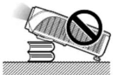
Do not block the exhaust and intake vents.
■Allow at least 7 78 inches (20 cm) of space between the exhaust vent and the nearest wall or obstruction.
■Ensure that the intake vent and the exhaust vent are not obstructed.
If the cooling fan becomes obstructed, a protection circuit will automatically put the projector into standby mode to prevent overheat damage. This does not indicate a malfunction (See pages 54 and 55.). Remove the projector power cord from the wall outlet and wait at least 10 minutes. Place the projector where the intake and exhaust vents are not blocked, plug the power cord back in and turn on the projector. This will return the projector to the normal operating condition.
Caution regarding usage of the projector
■ When using the projector, ensure not to subject it to hard impact and/or vibration, as this can result in damage. Take extra care with the lens. If you are not to use the projector for a long time, ensure to unplug the power cord from the wall outlet, and disconnect any other cables connected to it.
■Do not use the projector by holding the lens.
■ When you are not to use the projector for a long time, or storing the projector, ensure to attach the lens cap to the projector (See page 9.).
■Do not expose the projector to direct sunlight or near heat sources. The projector may change color or become deformed.
Other connected equipment
■When connecting a computer or other audio-visual equipment to the projector, make the connections AFTER unplugging the power cord of the projector from the AC outlet and turning off the equipment to be connected.
■Please read the operation manuals of the projector and the equipment to be connected for instructions on how to make the connections.
Using the projector in other countries
■The power supply voltage and the shape of the plug may vary depending on the region or country you are using the projector in. When using the projector overseas, ensure to use an appropriate power cord for the country you are in.
Temperature monitor function
■ If the projector starts to overheat due to setup
problems or blockage of the
air vents, "× and " " TEMP.
will illuminate in the lower left corner of the picture. If the
temperature continues to rise, the lamp will turn off, the temperature warning indicator on the projector will blink, and after a 90-second cooling-off period the projector will enter the standby mode. Refer to "Maintenance Indicators" on page 54 for details.

TEMP.

Info
- The cooling fan regulates the internal temperature, and its performance is automatically controlled. The sound of the fan may change during projector operation due to changes in the fan speed. This does not indicate malfunction.
- Do not unplug the power cord during projection or cooling fan operation. This can cause damage due to rise in internal temperature, as the cooling fan also stops.
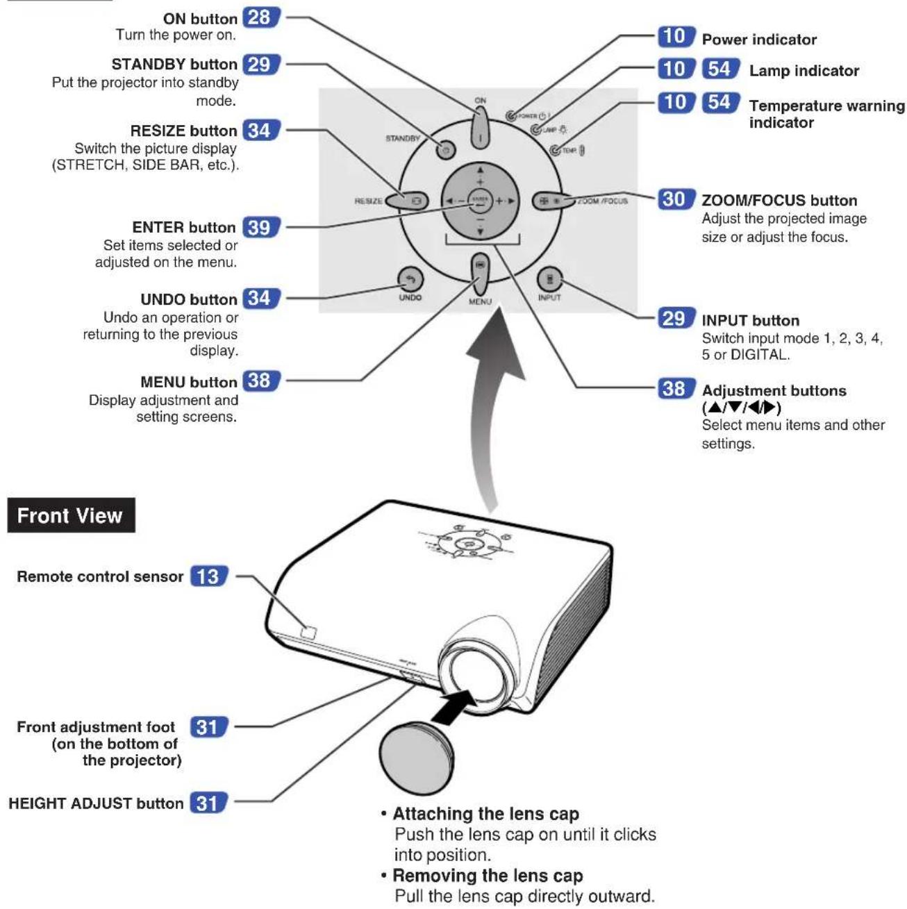
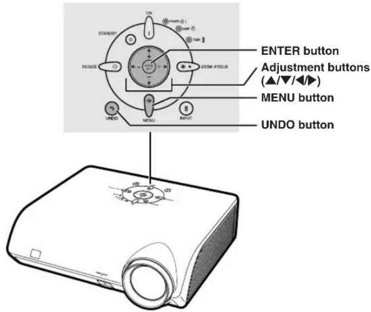
Part Names and Functions
Numbers in refer to the main pages in this operation manual where the topic is explained.
Projector
Top View
About the Indicators on the Projector
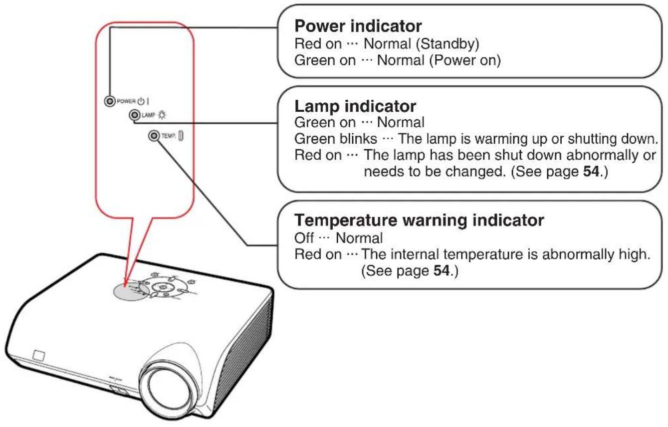
Numbers in refer to the main pages in this operation manual where the topic is explained.
Projector (Rear View)
Terminals Refer to "INPUT Terminals and Connectable Main Equipment" on page 19.
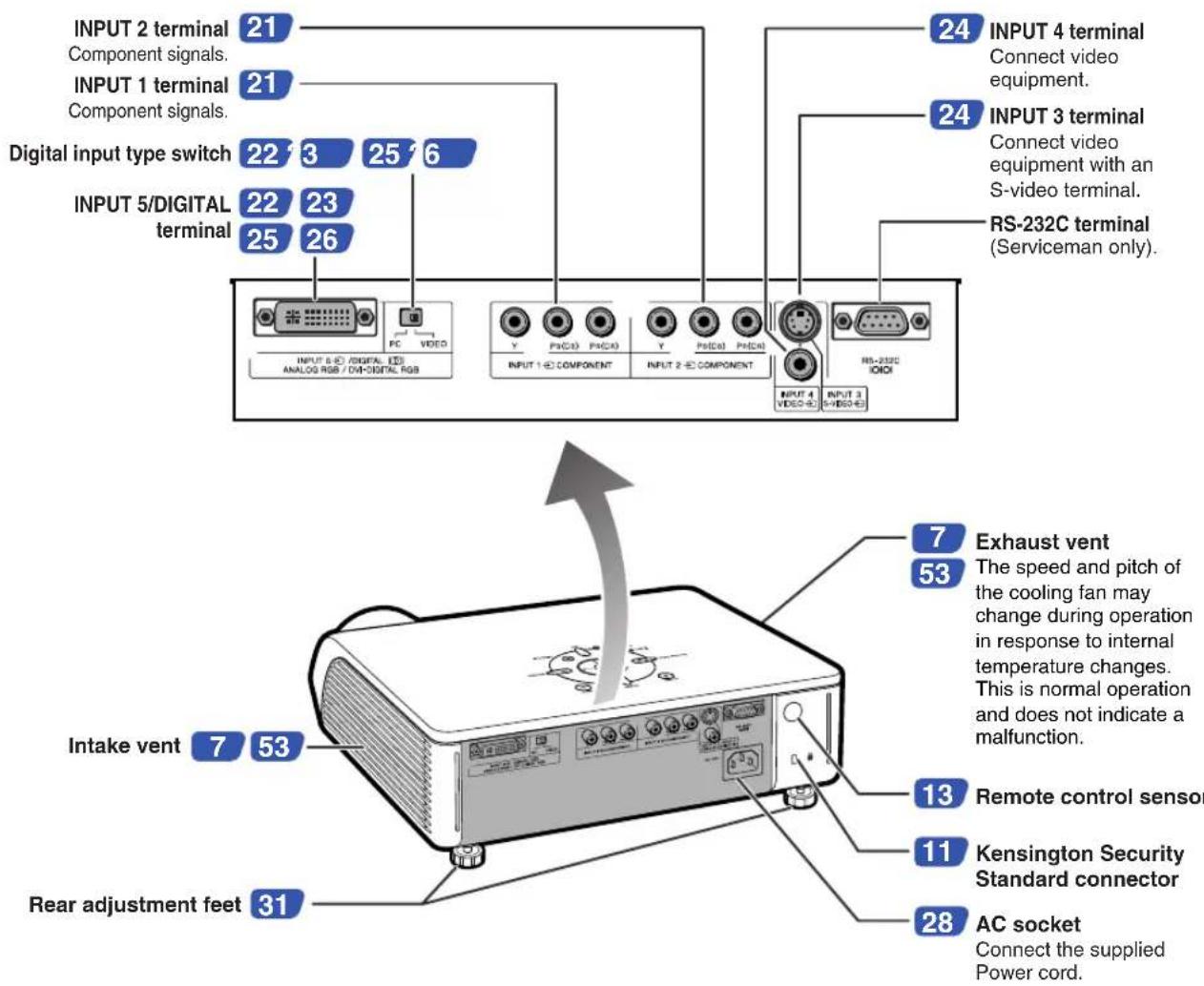
Using the Kensington Lock
- This projector has a Kensington Security Standard connector for use with a Kensington MicroSaver Security System. Refer to the information that came with the system for instructions on how to use it to secure the projector.
Numbers in refer to the main pages in this operation manual where the topic is explained.
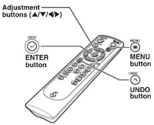
Remote Control
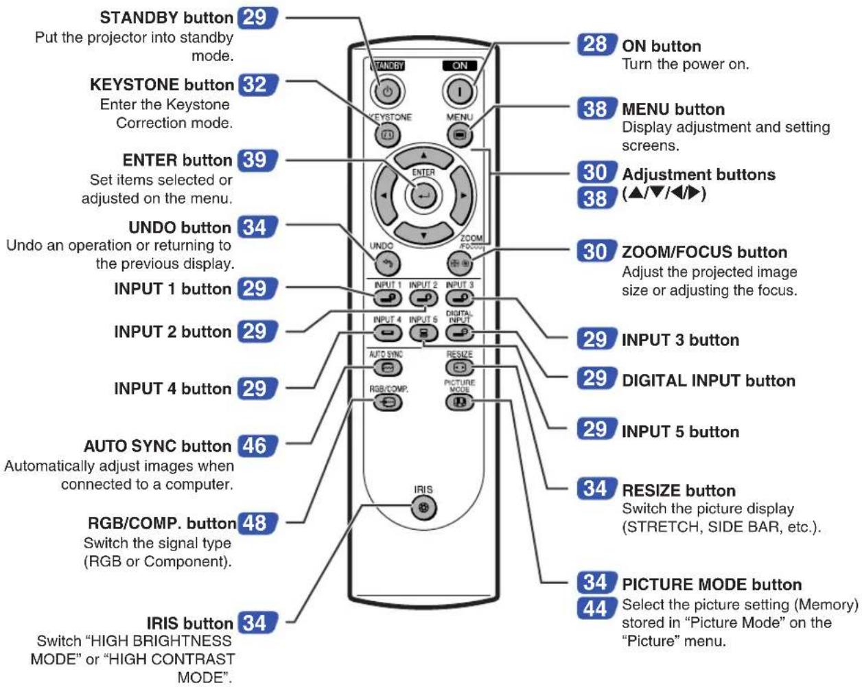

Note
- All the buttons on the remote control are made of luminous material that is visible in the dark. Visibility will diminish over time. Exposure to light will recharge the luminous buttons.
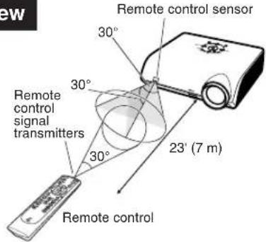
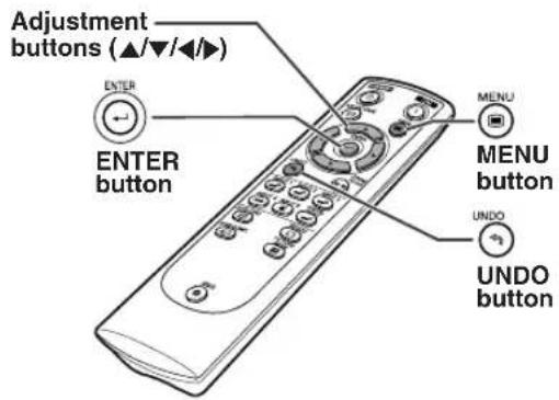
Using the Remote Control
Usable Range
The remote control can be used to control the projector within the ranges shown in the illustration.

Note
• The signal from the remote control can be reflected off a screen for easy operation. However, the effective distance of the signal may differ depending on the screen material.
When using the remote control:
- Ensure not to drop, expose to moisture or high temperature.
- The remote control may malfunction under a fluorescent lamp. In this case, move the projector away from the fluorescent lamp.
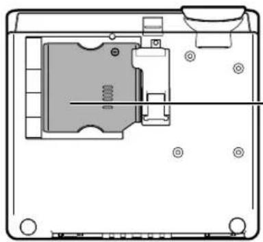
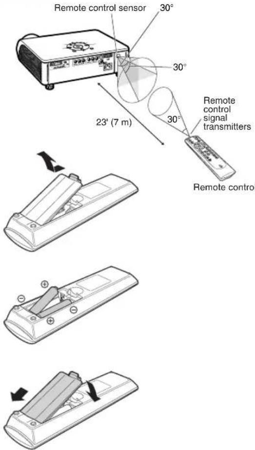
Inserting the Batteries
1
Pull down the tab on the cover and remove the cover towards the direction of the arrow.
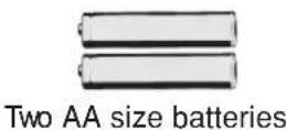
2
Insert the included batteries (two "AA" size).
- Insert the batteries making sure the polarities correctly match the ④ and - marks inside the battery compartment.
3
Insert the lower tab of the cover into the opening, and lower the cover until it clicks in place.
Front View
Rear View
Incorrect use of the batteries may cause them to leak or explode. Please follow the precautions below.

Caution
- Insert the batteries making sure the polarities correctly match the ④ and marks inside the battery compartment.
- Batteries of different types have different properties, therefore do not mix batteries of different types.
- Do not mix new and old batteries.
This may shorten the life of new batteries or may cause old batteries to leak. - Remove the batteries from the remote control once they have run out, as leaving them in can cause them to leak. Battery fluid from leaked batteries is harmful to skin, therefore ensure to first wipe them and then remove them using a cloth.
- The batteries included with this projector may run down in a short period, depending on how they are kept. Ensure to replace them as soon as possible with new batteries.
Quick Start
This section shows the basic operation. For details, see the page described below for each step.
Setup and Projection
Connection of the projector and the video equipment with an S-video terminal is explained as an example below.
1. Place the projector facing a screen
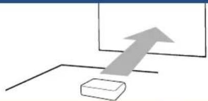
natural_image
Simple diagram showing a gray arrow pointing upward toward a rectangular block on a horizontal line (no text or symbols)→ Page 16
2. Connect the projector to the video equipment and plug the power cord into the AC socket of the projector
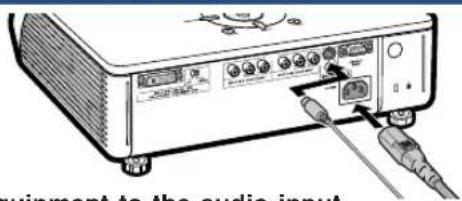
Connect the audio output terminal of the video equipment to the audio input terminal of the audio equipment using an audio cable.
→ Pages 21-27
3. Remove the lens cap and turn the projector on
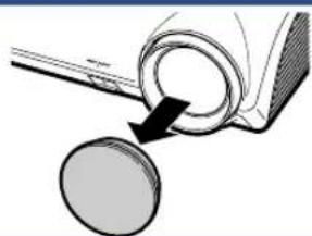
natural_image
Diagram showing a mechanical component with a circular component and an arrow pointing to it (no text or symbols present)On the remote control On the projector


→ Page 27
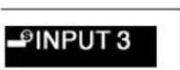
4. Select the INPUT mode
Select the "INPUT 3" using the INPUT button on the projector or the INPUT 3 button on the remote control.
On the projector

On the remote control

▼n-screen Display
- When pressing ⏻ on the projector, input mode switches in order of :
→ INPUT 1→ INPUT 2→ INPUT 3→ INPUT 4→ INPUT 5→ DIGITAL
- When using the remote control, press INPUT 1 INPUT 2 INPUT 3 INPUT 4 INPUT 5 INPUT to switch the INPUT mode.
→ Page 29
5. Turn the video equipment on and playback
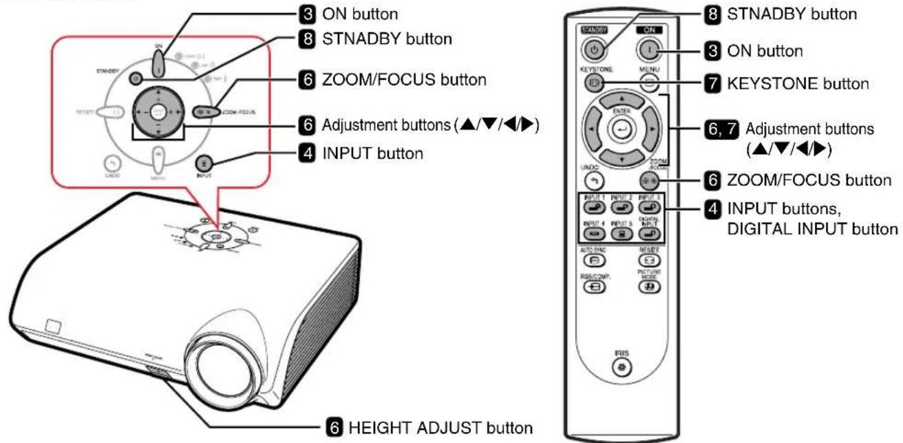
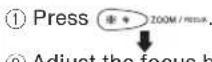
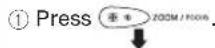
6. Adjust the projector angle, focus and zoom
1 Adjust the focus
On the projector
On the remote control

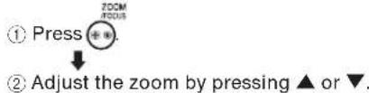
② Adjust the projected image size by adjusting zoom.
On the projector
② Adjust the zoom by pressing ▲ or ▼.

On the remote control
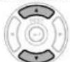
③Adjust the projector angle using the HEIGHT ADJUST button.
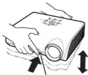
natural_image
Illustration of hands using a tool to lift a cylindrical object, with arrows indicating direction (no text or symbols)Correcting trapezoidal distortion using the Keystone Correction
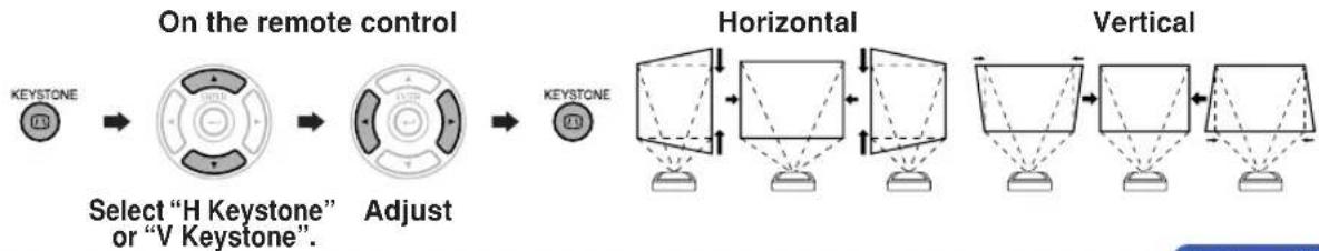
flowchart
graph LR
    A["KEystone"] --> B["Select "H Keystone" or "V Keystone""]
    B --> C["Adjust"]
    C --> D["KEystone"]
    D --> E["Horizontal"]
    E --> F["Vertical"]
→ Pages 32, 33
8. Turn the Power off
Press the STANDBY button, then press that button again while the confirmation message is displayed, to put the projector into standby mode.
On the projector

On the remote control

▼▼On-screen Display

- Unplug the power cord from the AC outlet after the cooling fan stops.
→ Page 28
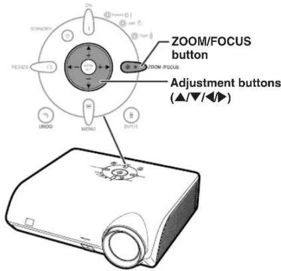
Setting Up the Projector
Position the projector perpendicular to the screen to achieve an optimal image.

Note
- The projector lens should be centered in the middle of the screen. If the horizontal line passing through the lens center is not perpendicular to the screen, the image will be distorted, making viewing difficult.
- For an optimal image, position the screen so that it is not in direct sunlight or room light. Light falling directly on the screen washes out the colors, making viewing difficult. Close the curtains and dim the lights when setting up the projector in a sunny or bright room.
Standard Setup (Front Projection)
Place the projector at the required distance from the screen according to the desired picture size. (See page 17.)
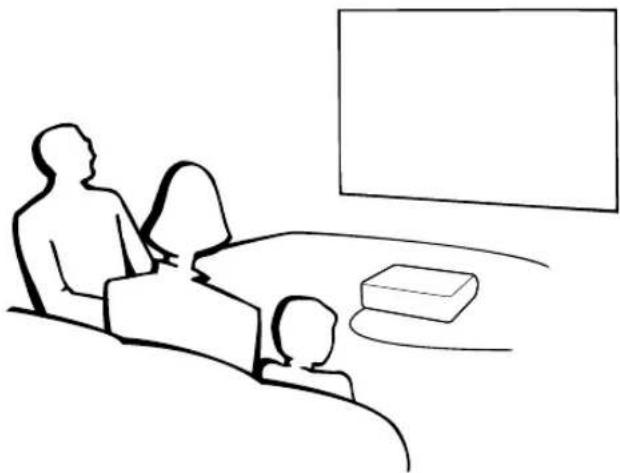
natural_image
Line drawing of a person watching a TV with a large screen in the background (no text or symbols)Indication of the Projection Image Size and Projection Distance
See “Screen Size and Projection Distance” on page 17 for details. Example : When using a wide screen (16:9)
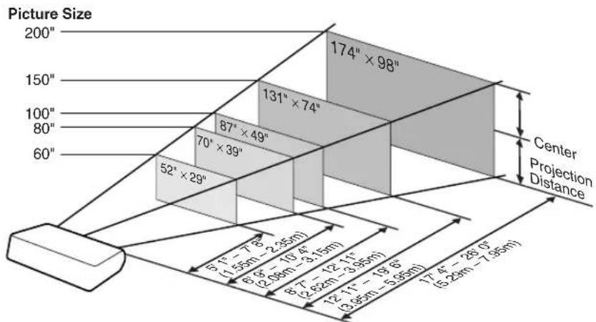
Screen Size and Projection Distance
The projection screen size varies according to the distance from the lens of the projector to the screen. Install the projector so that projected images are projected onto the screen at the optimum size by referring to the table below. Use the values in the table as a reference when installing the projector.
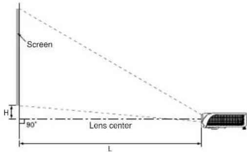
Side View
When using a wide screen (16:9):
In case of displaying the 16:9 picture on the whole of the 16:9 screen.
| Picture (Screen) size Projection distance [L] | Distance from the bottom of the image to the lens center [H] | ||||
| Diag. [X] Width Height Minimum [L1] Maximum [L2] | |||||
| 200" 174" | 98" 17' 4" (5.29 m) | 26' 0" (7.95 m) 3 | 9/32'' (8.3 cm) | ||
| 150" 131" | 74" 12' 11" (3.95 m) | 19' 6" (5.95 m) 2 | 29/64'' (6.2 cm) | ||
| 100" 87" | 49" 8' 7" (2.62 m) | 12' 11" (3.95 m) 1 | 21/32'' (4.2 cm) | ||
| 80" 70" | 39' 6' 9" (2.08 m) | 10' 4" (3.15 m) 1 | 5/16'' (3.3 cm) | ||
| 70" 61" | 34' 5' 11" (1.82 m) | 9' 0" (2.75 m) 1 | 5/32'' (2.9 cm) | ||
| 60" | 52" 29" | 5' 1" (1.55 m) | 7' 8" (2.35 m) | 63/64'' (2.5 cm) | |
| 40" | 35" 20" | 3' 3" (1.01 m) | 5' 1" (1.35 m) | 43/64'' (1.7 cm) | |
χ: Picture size (diag.) (inches)
L: Projection distance (ft/m)
L1: Minimum projection distance (ft/m)
L2: Maximum projection distance (ft/m)
H: Distance from the bottom of the image to the lens center (in/cm)
The formula for picture size and projection distance
[Feet/inches]
L1 (ft) = (0.02671x-0.05334) / 0.3048 L1 (m) = 0.02671x-0.05334
L2 (ft) = (0.03999x-0.05215) / 0.3048 L2 (m) = 0.03999x-0.05215
H (in) = 0.04151% / 2.54 H (cm) = 0.04151%
When using a normal screen (4:3):
In case of setting the 16:9 picture to the full horizontal width of the 4:3 screen.
| Picture (Screen) size Projection | distance [L] | Distance from the bottom of the image to the lens center [H] | |||
| Diag. [x.] Width Height Minimum [L1] Max | mum [L2] | ||||
| 200" | 160" | 120" | 15' 10" (4.85 m) | 23' 11" (7.29 m) | 3" (7.62 cm) |
| 150" | 120" | 90" | 11' 10" (3.62 m) | 17' 10" (5.45 m) | 2 1/64" (5.72 cm) |
| 100" | 80" | 60" | 7' 10" (2.40 m) | 11' 10" (3.62 m) | 1 1/2" (3.81 cm) |
| 80" 64" 48" | 6' 3" (1.91 m) | 9' 5" (2.88 m) 1 | 13/64" (3.05 cm) | ||
| 70" 56" 42" | 5' 5" (1.66 m) | 8' 3" (2.52 m) 1 | 1/16" (2.67 cm) | ||
| 60" 48" 36" | 4' 7" (1.42 m) | 7' 0" (2.15 m) | 57/64" (2.29 cm) | ||
| 40" | 32" | 24" | 3' 0" (0.93 m) | 4' 7" (1.42 m) | 39/64" (1.52 cm) |
x: Picture size (diag.) (inches)
L: Projection distance (ft/m)
L1: Minimum projection distance (ft/m)
L2: Maximum projection distance (ft/m)
H: Distance from the bottom of the image to the lens center (in/cm)
The formula for picture size and projection distance
[Feet/inches]
L1 (ft) = (0.02452% - 0.05334) / 0.3048 L1 (m) = 0.02452% - 0.05334
L2 (ft) = (0.03671x-0.05215) / 0.3048 L2 (m) = 0.03671x-0.05215
H (in) = 0.03810% / 2.54 H (cm) = 0.03810%
![SHARP DT-400 - [Feet/inches] - 1](/content/2026/06/1175767/images/13a6a2cab2393b782c11ab44e23e22b665dfb2c0cbaefc339575f0e5325da154.jpg)
Note
• There may be an error of ± 3% in the above values.
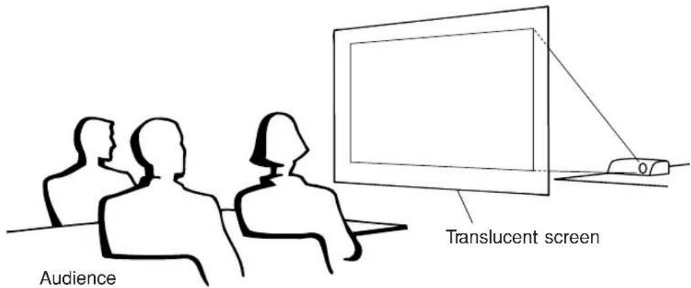
Projecting a Reversed Image
Projection from behind the Screen
■Place a translucent screen between the projector and the audience.
■ Reverse the image by setting "Rear" in the "PRJ Mode" menu. (See page 52.)
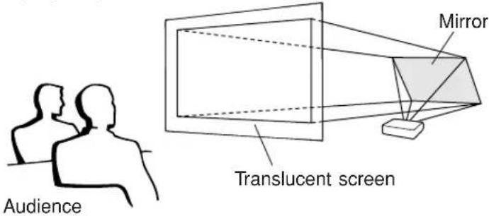
Projection Using a Mirror
■Place a mirror (normal flat type) in front of the lens.
■ When the translucent screen is placed between the mirror and audience, set to "Front" in the "PRJ Mode" menu. (See page 52.)
■ When the mirror is placed on the audience side, set to "Rear" in the "PRJ Mode" menu. (See page 52.)
Set to "Front"
Set to "Rear"
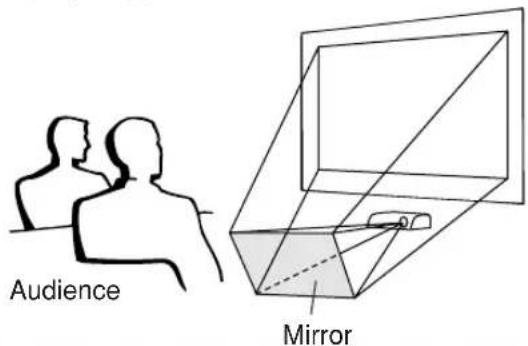

Info
- When using a mirror, ensure to carefully position both the projector and the mirror so the light does not shine into the eyes of the audience.
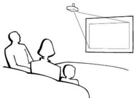
Ceiling-mount Setup
It is recommended that you use the optional Sharp ceiling-mount bracket for this installation.
■Before mounting the projector, contact your nearest Sharp Authorized Service Center or Dealer to obtain the recommended ceiling-mount bracket (commercially available). (AN-CM270 ceiling-mount bracket, AN-EP101B extension tube for AN-CM270.)
■Invert the image by setting "Ceiling + Front" in "PRJ Mode". See page 52 for use of this function.
natural_image
Line drawing of a family watching a screen with a projector (no text or symbols)INPUT Terminals and Connectable Main Equipment
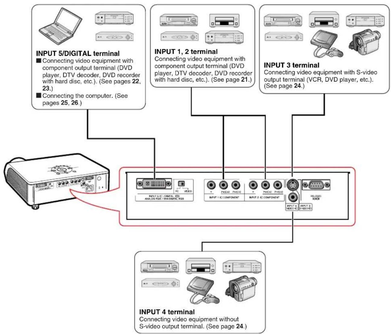
flowchart
graph TD
    A["INPUT 5/DIGITAL terminal"] --> B["Connecting video equipment with component output terminal (DVD player, DTV decoder, DVD recorder with hard disc, etc.). (See pages 22, 23.)"]
    A --> C["Connecting the computer. (See pages 25, 26.)"]
    D["INPUT 1, 2 terminal"] --> E["Connecting video equipment with component output terminal (DVD player, DTV decoder, DVD recorder with hard disc, etc.). (See page 21.)"]
    D --> F["Connecting video equipment with S-video output terminal (VCR, DVD player, etc.). (See page 24.)"]
    G["INPUT 3 terminal"] --> H["Connecting video equipment with S-video output terminal (VCR, DVD player, etc.). (See page 24.)"]
    G --> I["Connecting video equipment without S-video output terminal. (See page 24.)"]
    J["INPUT 4 terminal"] --> K["Connecting video equipment without S-video output terminal. (See page 24.)"]
Samples of Cables for Connection
- For more details of connection and cables, refer to the operation manual of the connecting equipment.
- You may need other cables or connectors not listed below.
| Equipment | Terminal on connected equipment | Cable | Terminal on the projector |
Audio-visual equipment    Computer Computer | Component video output terminal | Component cable (commercially available) | INPUT 1, 2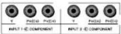 |
| Terminal for using the dedicated cable | Dedicated cable attached to the connected equipment.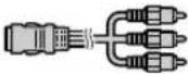 | INPUT 1, 2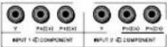 | |
| DVI output terminal | DVI cable (sold separately: AN-C3DV)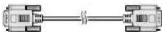 | INPUT 5/DIGITAL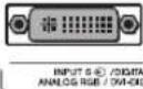 | |
| RGB output terminal | RGB cable (commercially available)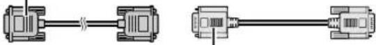 DVI to 15-pin D-sub adapter (sold separately: AN-A1DV) DVI to 15-pin D-sub adapter (sold separately: AN-A1DV) | INPUT 5/DIGITAL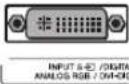 | |
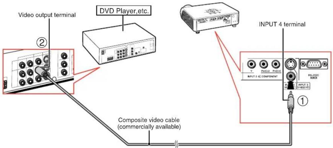
| Video output terminal | Video cable (commercially available)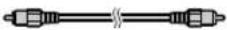 | INPUT 4 | |
| Terminal for using the dedicated cable | Dedicated cable attached to the connected equipment.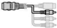 | INPUT 4 | |
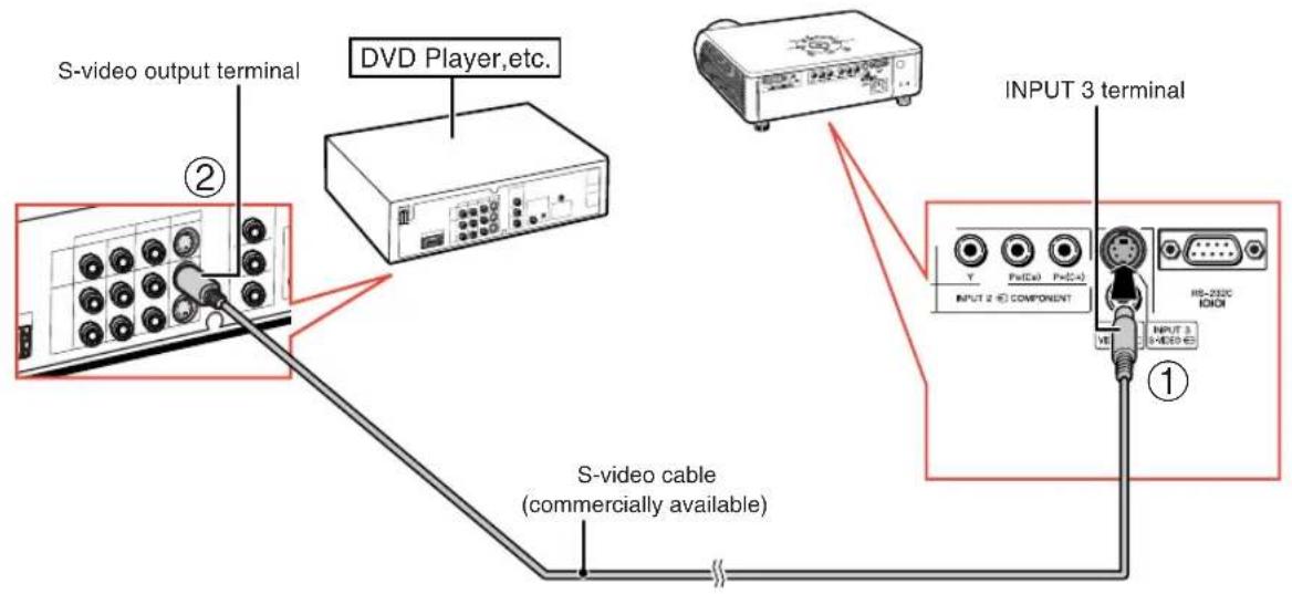
| S-video output terminal | S-video cable (commercially available)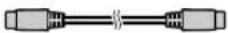 | INPUT 3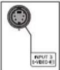 | |
| Terminal for using the dedicated cable | Dedicated cable attached to the connected equipment.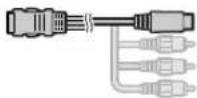 | INPUT 3 |
Connecting to Video Equipment
Before connecting, ensure to unplug the power cord of the projector from the AC outlet and turn off the devices to be connected. After making all connections, turn on the projector and then the other devices.
Ensure to read the operation manuals of the devices to be connected before making connections.
When connecting the component video equipment to the component input terminal on the projector (INPUT 1 or INPUT 2)
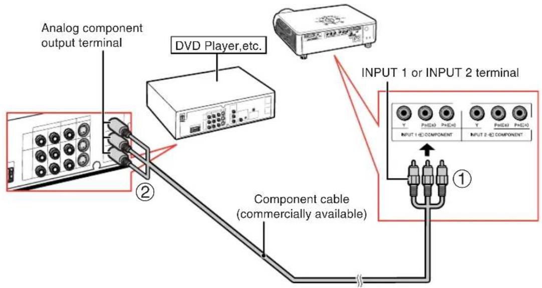
flowchart
graph TD
    A["Analog component output terminal"] --> B["Component cable (commercially available)"]
    B --> C["DVD Player,etc."]
    C --> D["INPUT 1 or INPUT 2 terminal"]
    D --> E["OUTPUT 1 HD COMPONENT"]
    D --> F["OUTPUT 2 HD COMPONENT"]
When connecting the component video equipment to the DVI input terminal on the projector (INPUT 5)
- Before connecting the cable, switch the digital input type switch to "VIDEO".
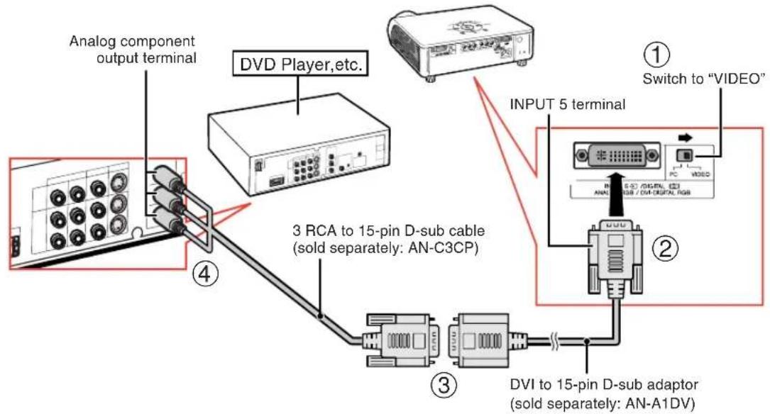
flowchart
graph TD
    A["Analog component output terminal"] --> B["3 RCA to 15-pin D-sub cable (sold separately: AN-C3CP)"]
    B --> C["DVI to 15-pin D-sub adaptor (sold separately: AN-A1DV)"]
    C --> D["INPUT 5 terminal"]
    D --> E["Switch to "VIDEO""]
    style A fill:#f9f,stroke:#333
    style B fill:#ccf,stroke:#333
    style C fill:#cfc,stroke:#333
    style D fill:#fcc,stroke:#333

Note
- For this connection, select "Component" for "Signal Type" on the OSD menu or press 📄 on the remote control. (See page 48.)
When connecting the video equipment with RGB output terminal (INPUT 5)
- Before connecting the cable, switch the digital input type switch to "VIDEO".
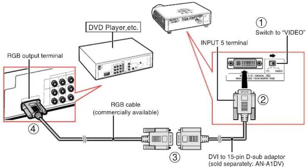

Note
- For this connection, select "RGB" for "Signal Type" on the OSD menu or press RGB/COMP. on the remote control. (See page 48.)
When connecting the video equipment with DVI output terminal (DIGITAL INPUT)
- Before connecting the cable, switch the digital input type switch to "VIDEO".
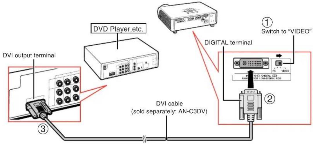

Note
- Select DIGITAL mode when connecting to video equipment with the digital output terminal. (See page 29.)
Connecting to Video Equipment
When connecting video equipment with S-video output terminal (INPUT 3)
When connecting video equipment with video output terminal (INPUT 4)
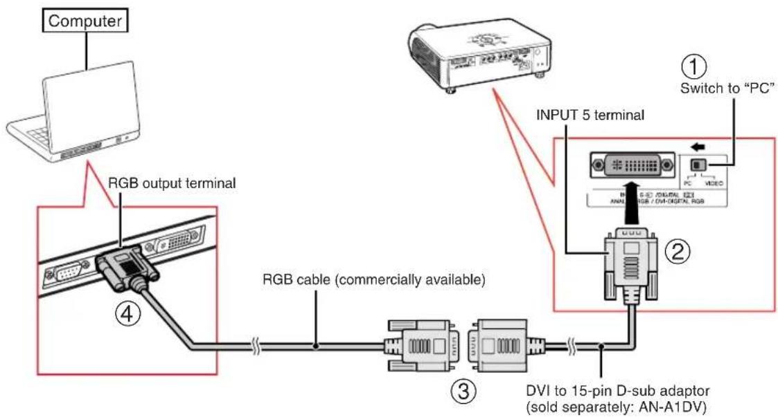
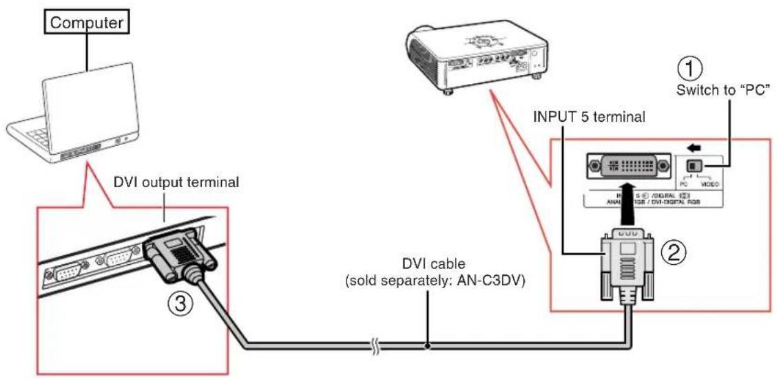
Connecting to a Computer
When connecting a computer, ensure that it is the last device to be turned on after all the connections are made.
Connecting to a computer (INPUT 5)
- Before connecting the cable, switch the digital input type switch to "PC".
flowchart
graph TD
    A["Computer"] --> B["RGB output terminal"]
    B --> C["USB port"]
    C --> D["RGB cable (commercially available)"]
    D --> E["DVI to 15-pin D-sub adaptor (sold separately: AN-A1DV)"]
    E --> F["INPUT 5 terminal"]
    F --> G["Switch to "PC""]
    style A fill:#f9f,stroke:#333
    style G fill:#ccf,stroke:#333

Note
- Refer to "Computer Compatibility Chart" on page 60 for a list of computer signals compatible with the projector. Use with computer signals other than those listed may cause some of the functions not to work.
- When connecting the projector to a computer in this way, select "RGB" for "Signal Type" on the OSD menu or press RGB/COMP. on the remote control. (See page 48.)
- A Macintosh adaptor may be required for use with some Macintosh computers. Contact your nearest Sharp Authorized Service Center or Dealer.
- Depending on the computer you are using, an image may not be projected unless the signal output setting of the computer is switched to the external output. Refer to the computer operation manual for switching the computer signal output settings.
When connecting a computer, ensure that it is the last device to be turned on after all the connections are made.
Connecting to a computer with DIGITAL RGB output Terminal (DIGITAL)
- Before connecting the cable, switch the digital input type switch to "PC".

Note
- Select DIGITAL mode when connecting to digital output terminal of the computer. (See page 29.)
- Before switching "Digital input type switch" and connecting, ensure to unplug the power cord of the projector from the AC outlet and turn off the computer to be connected. After making all connections, turn on the projector and then the computer.
"Plug and Play" function
This projector is compatible with VESA-standard DDC 1/DDC 2B. The projector and a VESA DDC compatible computer will communicate their setting requirements, allowing for quick and easy setup.
Before using the "Plug and Play" function, ensure to turn on the projector first and the connected computer last.

Note
- The DDC "Plug and Play" function of this projector operates only when used in conjunction with a VESA DDC compatible computer.
Turning the Projector On/Off
Connecting the Power Cord
Plug the supplied power cord into the AC socket.
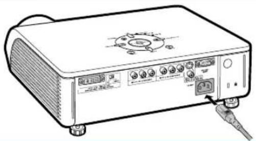
Turning the Projector On
Before performing the steps in this section, connect any equipment that you use with the projector. (See pages 19-26.)
Remove the lens cap and press on the projector or ☑ on the remote control.
• The power indicator illuminates green.
• After the lamp indicator illuminates, the projector is ready to start operation.

Note
- The lamp indicator illuminates or blinks, indicating the status of the lamp.
Green:The lamp is ready.
Blinking green: The lamp is warming up or shutting down.
Red: The lamp is shut down abnormally or the lamp should be replaced.
- When switching on the projector, a slight flickering of the image may be experienced within the first minute after the lamp has been illuminated. This is normal operation as the lamp's control circuitry is stabilising the lamp output characteristics. This does not indicate malfunction.
- If the projector is put into standby mode and immediately turned on again, the lamp may take some time to illuminate.
natural_image
Line drawing of a portable electronic device with ports and a cable connector (no text or symbols)
Info
- English is the factory preset language. If you want to change the on-screen display to another language, change the language according to the procedure on page 52.
Turning the Power Off (Putting the Projector into Standby Mode)
1
STANDBY

Press on the projector or on the remote control, then press that button again while the confirmation message is displayed, to put the projector into standby mode.
▼On-screen Display

Enter STANDBY mode?
Yes:Press Again. No:Please Wait.

Shutting Down. Please Wait.
2
Unplug the power cord from the AC outlet after the cooling fan stops.

Info
- Do not unplug the power cord during projection or cooling fan operation. The cooling fan in this projector continues to run for about 90 seconds after the projector enters the standby mode. This can cause damage due to rise in internal temperature, as the cooling fan also stops.
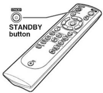
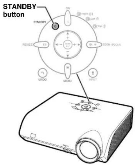
Image Projection
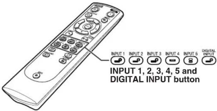
Switching the INPUT Mode
Select the appropriate input mode for the connected equipment.
Press INPUT 1, INPUT 2, INPUT 3, INPUT 4, INPUT 5 or DIGITAL INPUT on the remote control to select the input mode.
- When pressing ⏻ on the projector, input mode switches in order of :
[INPUT 1 INPUT 2 INPUT 3 DIGITAL ← INPUT 5 INPUT 4]

Note
- When no signal is received, "NO SIGNAL" will be displayed. When a signal that the projector is not preset to receive is received, "NOT REG." will be displayed.
- The INPUT mode is not displayed when "OSD Display" of the "Options" menu is set to "☐ (OFF)". (See page 47.)
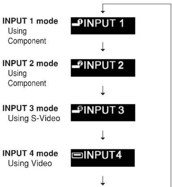
About the INPUT mode
| INPUT 1 (Component) | Used for projecting images from equipment connected to INPUT 1 terminals. |
| INPUT 2 (Component) | Used for projecting images from equipment connected to INPUT 2 terminal. |
| INPUT 3 (S-Video) | Used for projecting images from equipment connected to INPUT 3 terminal. |
| INPUT 4 (Video) | Used for projecting images from equipment connected to INPUT 4 terminal. |
| INPUT 5 (Component/ RGB) | Used for projecting images from equipment connected to INPUT 5 terminal. |
| DIGITAL | Used for projecting images from equipment with DVI or RGB output terminal connected to INPUT 5 terminal. |
▼On-screen Display of INPUT Mode (Example)
flowchart
graph TD
    A["INPUT 1 mode\nUsing Component"] --> B["INPUT 2"]
    B --> C["INPUT 3"]
    C --> D["INPUT 4"]
INPUT 5 mode
Component
RGB


- When switching the component and RGB input mode, press RGB/COMP the remote control or select "Signal Type" in the "Options" menu.
DIGITAL mode
DIGITAL
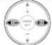
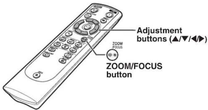
Adjusting the Focus
1 Press on the remote control.
2 Press ◀ or ▶ on the remote control to adjust the focus.

- You can also adjust the focus by using * ZOOM /FOCUS and ◀ or ▶ on the projector.
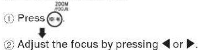
Adjusting the Projected Image Size
1 Press on the remote control.
2 Press ▲ or ▼ on the remote control to adjust the zoom.

- You can also adjust the zoom by using ZOOM /FOCUS and ▲▲▼ on the projector.
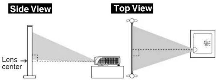
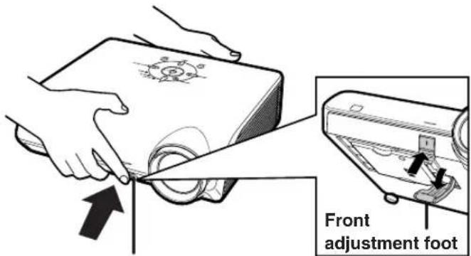
Using the Adjustment Feet
The height of the projector can be adjusted using the adjustment feet at the front and rear of the projector when the screen is located higher than the projector, the screen is inclined or when the installation site is slightly inclined. Install the projector so that it is as perpendicular to the screen as possible.
1 Lift the projector to adjust its height while pressing the HEIGHT ADJUST button.
- The projector is adjustable up to approximately 12 degrees (6 steps).
- When lowering the projector, it may be difficult to move the front adjustment foot because the installation surface is difficult to slide. In this case, pull the projector back slightly and adjust its height.
2 Remove your hands from the HEIGHT ADJUST button of the projector after its height has been finely adjusted.
3 Finely adjust the height and inclination by turning the rear adjustment feet.

Note
- When adjusting the projected image position, trapezoidal distortion occurs. In this case, see "Keystone Correction" on page 32.

Info
- Do not press the HEIGHT ADJUST button when the front adjustment foot comes out without firmly holding the projector.
- Do not hold the lens when lifting or lowering the projector.
- When lowering the projector, be careful not to get your fingers caught in the area between the adjustment foot and the projector.
natural_image
Illustration of hands holding a device with a magnified view showing internal components (no text or symbols)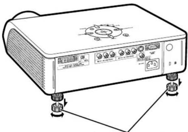
natural_image
Line drawing of a portable electronic device with control knobs and buttons, shown with rotation arrows (no text or symbols)Rear adjustment feet
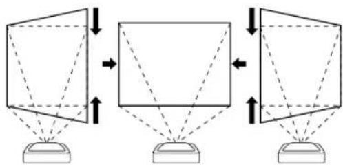
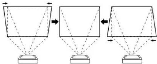
Keystone Correction
This function can be used to adjust the Keystone settings.

Note
- When the image is projected from a direction at an angle, the image becomes distorted trapezoidally. The function for correcting trapezoidal distortion is called Keystone Correction.
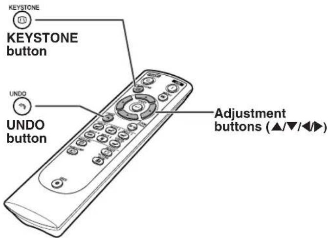
1
Press on the remote control to enter the Keystone Correction mode.
2
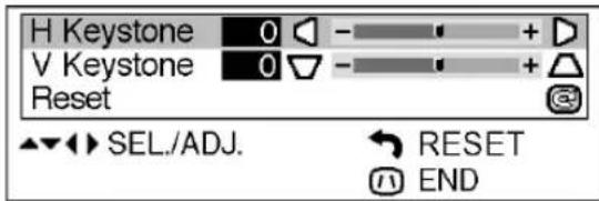
Press ▲/▼ to select "H Keystone" or "V Keystone".
| Selectable items | Description |
| H Keystone | Horizontally adjusts the keystone settings. |
| V Keystone | Vertically adjusts the keystone settings. |
| Reset | Returns to the factory preset settings. |
3
Press ◀/▶ to move the ▼ mark on the selected adjustment item to the desired setting.

Note
- Straight lines and the edges of the displayed image may appear jagged, when adjusting the Keystone setting.
- When adjusting "H Keystone" and "V Keystone" at the same time, the values of adjustable angles for each setting become smaller.
- The adjustable value of the "V Keystone" becomes extremely small when "H Keystone" is made to be the maximum value.
- Keystone correction is disabled while the picture mode is set to "SMART STRETCH". (See page 35.)
4
Press

- The on-screen display of the Keystone Correction mode will disappear.
▼On-screen Display (Keystone Correction mode)
Horizontal Keystone Correction
flowchart
graph TD
    A["Top Top"] --> B["Top Left"]
    B --> C["Top Right"]
    C --> D["Bottom Top"]
    style A fill:#f9f,stroke:#333
    style B fill:#ccf,stroke:#333
    style C fill:#cfc,stroke:#333
    style D fill:#fcc,stroke:#333
Vertical Keystone Correction
flowchart
graph TD
    A["Rectangular Shape"] --> B["Square Shape"]
    B --> C["Geometric Shape"]

Note
- When adjusting the Keystone setting, the placement range is changed depending on the input signal type.
- Keystone correction cannot be applied to On-screen Display.
- When Keystone correction is applied, the resolution of image can be deteriorated to some extent.
- Keystone Correction is also returned to the factory preset settings by pressing Ⓔ on the remote control.
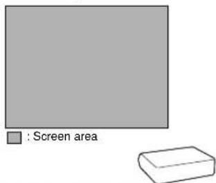
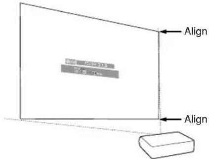
Placement of the Projected Image Using the Keystone Correction
Place the projector at a distance from the screen that allows images to be projected onto the screen by referring to "Screen Size and Projection Distance" on page 17.

Note
- The aspect ratio of the projected image also shifts slightly when the "H Keystone" and "V Keystone" functions are adjusted simultaneously.
- If you cannot correct trapezoidal distortion with Keystone correction, change the placement position of the projector.
1
Project the test pattern of the Keystone correction function onto the screen. Adjust the focus until the image on the screen comes into focus. (See page 30.)
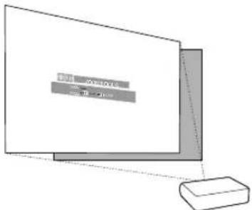
2
Change the projection angle moving the projector or using the adjuster to properly project images onto the screen. (See page 31).
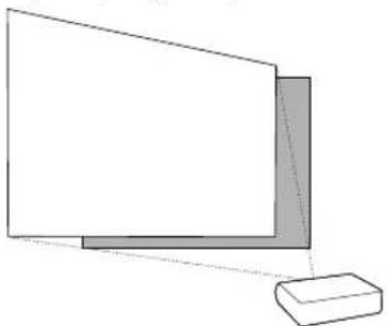
natural_image
Simple line drawing of a 3D geometric shape with a rectangular base and an L-shaped corner (no text or symbols)3
Align the edge of the screen closest to the projector with the test pattern by adjusting the zoom and the adjsuter. (See pages 30 and 31.)
Adjust the Keystone function so that the size of the projected image matches the screen size. (See page 32.)
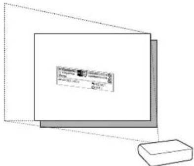
5
Align the image on the screen by adjusting the zoom function and the adjsuter.
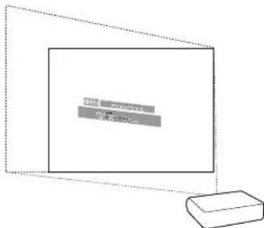
Adjust the focus so that the projected image is in focus at the center of the screen. (See page 30.)
Selecting the Picture Mode
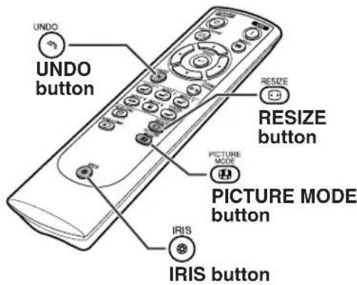
You can select the picture setting (Memory) directly stored in "Picture Mode" on the "Picture" menu.
Press MODE on the remote control.
• Each time the button is pressed while the display is on, the picture mode changes in order of:
Memory OFF Memory 1 Memory 2 Memory 5 Memory 4 Memory 3

Note
- This function can also be accessed from the OSD menu (see page 44).
Switching the High Brightness / High Contrast Mode
This function controls the quantity of the projected light and the contrast of the image.
Press IRIS on the remote control.
- Each time the button is pressed while the display is on, the mode is switched between "HIGH BRIGHTNESS MODE" and "HIGH CONTRAST MODE".

Note
- This function can also be accessed from the OSD menu (see page 44).
Adjusting the Picture Aspect Ratio
This function allows you to modify or customize the picture display mode to enhance the input image. Depending on the input signal, you can choose STRETCH, SIDE BAR, SMART STRETCH or CINEMA ZOOM image.
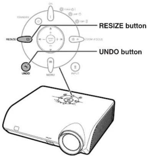
Press 📄 on the remote control.
• Each time 📊 is pressed, the picture mode changes as shown on the next page.
- Toreturn to the standard image ("STRETCH"), press
UNDO while "RESIZE" is displayed on the screen.
- You can also change the picture display mode by pressing RESIZE on the projector.
| Input signal | Output screen image | ||
| STRETCH CINEMA ZOO SIDE BAR SMART STRETCH | |||
| 4801 480P 576P 576P NTSC PAL SECAM | 4:3 aspect ratio | ||
| Letterocx | |||
| Squeeze | |||
| 16:9 aspect ratio | |||
| 540F 1080I | 16:9 aspect ratio | ||
| 720F | 16:9 aspect ratio | ||
| VGA SVGA XGA | 4:3 aspect ratio | ||

Note
- "SMART STRETCH" cannot be selected while the Keystone correction (page 32) is being adjusted.
- Keystone correction (page 32) is disabled while the picture mode is set to "SMART STRETCH".
- 580I/580P is displayed on the screen when signal 576I/576P is input.
- "STRETCH" is fixed when 540P, 720P or 1080 signal is entered.
- "SMART STRETCH" cannot be selected while input signal from a computer (VGA, SVGA or XGA) is entered.
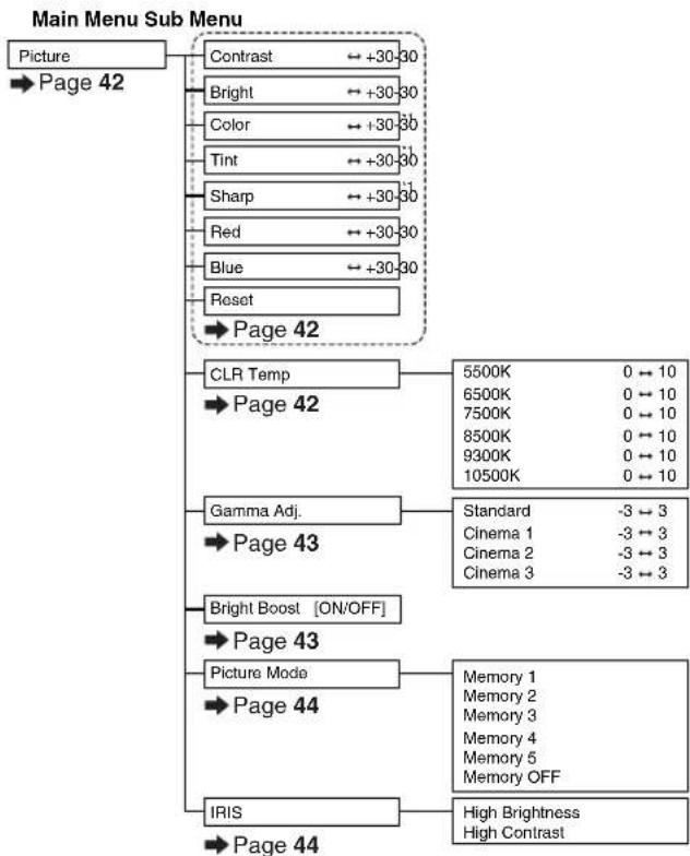
The following shows the items that can be set in the projector.
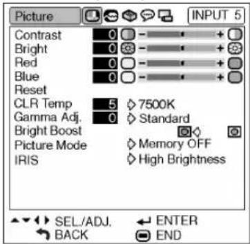
"Picture" menu
Example: Screen for INPUT 1 mode
Example: Screen for INPUT 5 (RGB) mode
flowchart
graph TD
    A["Picture"] --> B["Page 42"]
    B --> C["Contrast ← +30→30"]
    B --> D["Bright ← +30→30"]
    B --> E["Color ← +30→30"]
    B --> F["Tint ← +30→30"]
    B --> G["Sharp ← +30→30"]
    B --> H["Red ← +30→30"]
    B --> I["Blue ← +30→30"]
    B --> J["Reset"]
    J --> K["Page 42"]
    K --> L["CLR Temp"]
    L --> M["5500K 0 → 10"]
    L --> N["6500K 0 → 10"]
    L --> O["7500K 0 → 10"]
    L --> P["8500K 0 → 10"]
    L --> Q["9300K 0 → 10"]
    L --> R["10500K 0 → 10"]
    K --> S["Page 42"]
    S --> T["Gamma Adj."]
    T --> U["Standard -3 → 3"]
    T --> V["Cinema 1 -3 → 3"]
    T --> W["Cinema 2 -3 → 3"]
    T --> X["Cinema 3 -3 → 3"]
    K --> Y["Page 43"]
    Y --> Z["Bright Boost [ON/OFF"]]
    Z --> AA["Page 43"]
    Z --> AB["Picture Mode"]
    AB --> AC["Memory 1"]
    AB --> AD["Memory 2"]
    AB --> AE["Memory 3"]
    AB --> AF["Memory 4"]
    AB --> AG["Memory 5"]
    AB --> AH["Memory OFF"]
    Z --> AI["Page 44"]
    AI --> AJ["IRIS"]
    AJ --> AK["High Brightness"]
    AJ --> AL["High Contrast"]
*1: Items when selecting INPUT 1, 2, 3, 4 or when inputting component signal through INPUT 5
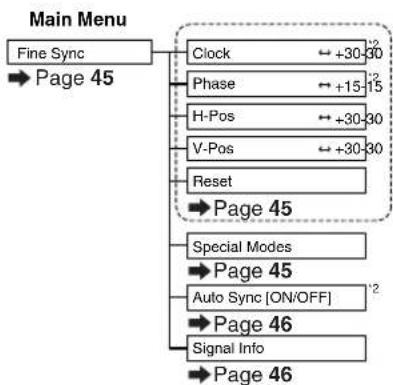
"Fine Sync" menu
Example: Screen for INPUT 5 (RGB) mode
flowchart
graph TD
    A["Fine Sync"] --> B["Page 45"]
    B --> C["Clock ← +30-30"]
    B --> D["Phase ← +15-15"]
    B --> E["H-Pos ← +30-30"]
    B --> F["V-Pos ← +30-30"]
    B --> G["Reset"]
    G --> H["Page 45"]
    H --> I["Special Modes"]
    I --> J["Page 45"]
    I --> K["Auto Sync [ON/OFF"] ^2]
    K --> L["Page 46"]
    K --> M["Signal Info"]
    M --> N["Page 46"]
*2: Item when inputting RGB signal through INPUT 5

Note
- "Tint" cannot be used with PAL, SECAM, PAL-M, PAL-N or PAL-60.
- "Color", "Tint", "Sharp", "Clock", "Phase", "H-Pos", "V-Pos" and "Auto Sync" cannot be used in the DIGITAL mode.
- "Fine Sync" menu cannot be displayed in the INPUT 3 and INPUT 4 modes.
"Options" menu
Example: Screen for INPUT 1 mode
Example: Screen for INPUT 4 mode
"Language" menu
"PRJ Mode" menu
Main Menu Sub Menu
flowchart
graph TD
    A["Options"] --> B["Lamp Timer (Life)"]
    B --> C["Page 47"]
    C --> D["OSD Display [ON/OFF"]]
    D --> E["Page 47"]
    E --> F["Video System"]
    F --> G["Page 48"]
    G --> H["Signal Type"]
    H --> I["Page 48"]
    I --> J["Background [Blue/None"]]
    J --> K["Page 49"]
    K --> L["Eco Mode [Eco/Standard"]]
    L --> M["Page 49"]
    M --> N["Auto Power Off [ON/OFF"]]
    N --> O["Page 50"]
    O --> P["Menu Position"]
    P --> Q["Page 50"]
    Q --> R["Menu Color [Opaque/Translucent"]]
    R --> S["Page 51"]
    G --> T["RGB Component"]
    T --> U["Auto PAL NTSC3.58 SECAM NTSC4.43 PAL-M PAL-N PAL-60"]
    U --> V["Center Upper Right Lower Right Upper Left Lower Left"]
*1: Item when selecting INPUT 3 or INPUT 4
*2: Item when selecting INPUT 5
Main Menu
flowchart
graph TD
    A["Language"] --> B["Page 52"]
    B --> C["English\nDeutsch\nEspañol\nNederlands\nFrançais\nItaliano\nSvenska\nPortuguês\n汉语\n한국어\n日本語"]
Main Menu
Using the Menu Screen
The menu can be operated to achieve two functions, adjustments and settings. (For setting the menu items, see pages 40 and 41.)
Menu Selections (Adjustments)
- This operation can also be performed by using the buttons on the projector.
1
Press

- The "Picture" menu screen for the selected input mode is displayed.
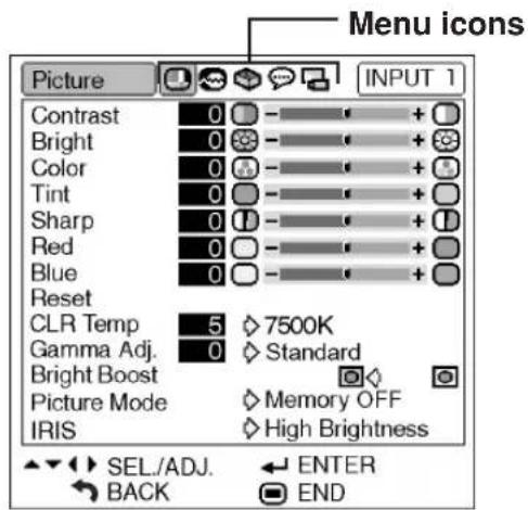
2
Press ▶ or ◀ to display the other menu screens.
- The menu icon for the selected menu screen is highlighted.
| Menu icon Menu screen | |
| Picture | |
| Fine Sync | |
| Options | |
| Language | |
| PRJ Mode | |

Note
- The "Fine Sync" menu is not available for selecting INPUT 3 or 4.
Example: "Picture" menu screen for INPUT 1 mode
3
Press ▲▲r▼▼ to select the item you want to adjust.
- The selected item is highlighted. (Example: Selecting "Bright")
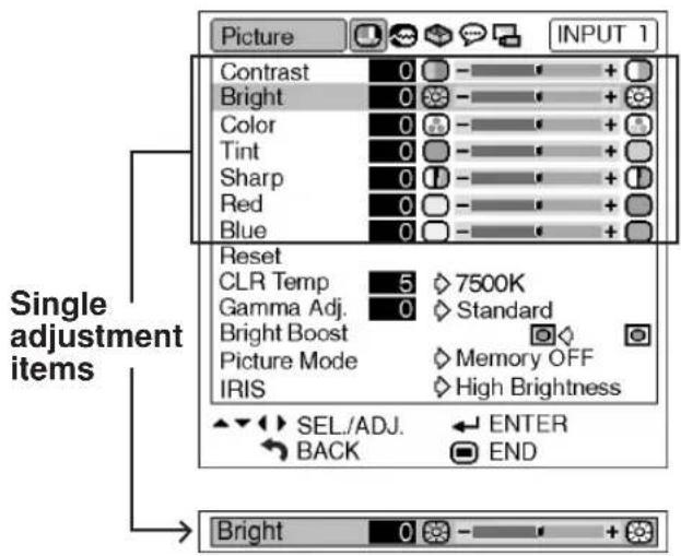
To adjust the projected image while viewing it
Press

- The selected single adjustment item (e.g. "Bright") appears on the lower part of the screen.
- When pressing ▲ or ▼, the next item will be displayed. (e.g. "Bright" is replaced with "Color" by pressing ▼.)

Note
- Press 📋 to return to the previous screen.
4
Press ▶ or ◀ to adjust the item selected.
• The adjustment is stored.
5
Press

• The menu screen will disappear.
The menu can be operated to achieve two functions, adjustments and settings. The “setting” item is displayed by ◇ or ➕ on the menu screen. (For adjusting the menu items, see pages 38 and 39.)
Menu Selections (Settings)
- This operation can also be performed by using the buttons on the projector.
1
Press

- The "Picture" menu screen for the selected input mode is displayed.
2
Press ▶ or ◀ to display the other menu screens.
- The menu icon for the selected menu screen is highlighted.
| Menu icon Menu screen | |
| Picture | |
| Fine Sync | |
| Options | |
| Language | |
| PRJ Mode | |

Note
- The "Fine Sync" menu is not available for selecting INPUT 3 or 4.
Example: "Picture" menu screen for INPUT 1 mode
Example: "Options" menu screen
3 Press ▲▲r▼▼ to select the item you want to set, and then press ▶ to display the sub menu.
- The selected item is highlighted. (Example: Selecting "Menu Position")

Note
- Press 📊 or ◀ to return to the previous screen.
- For some items, press ◀ or ▶ to select the icon using “◀”.
4 Press ▲▲r ▼▼o select the setting of the item displayed in the sub menu.
5 Press • The selected item is set.
6 Press MENU • The menu screen will disappear.
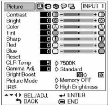
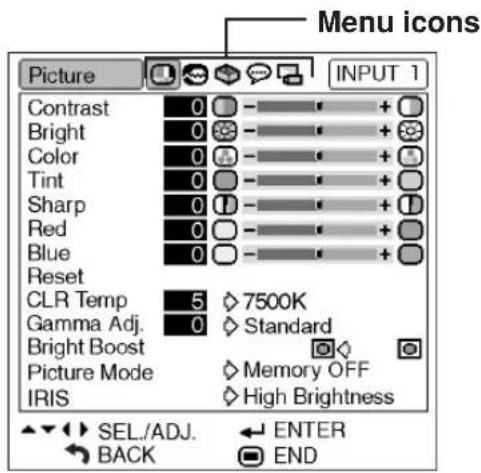
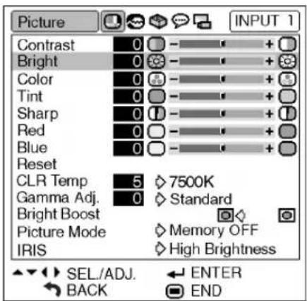
Picture Adjustment ("Picture" menu)
You can adjust the projector's picture to your preferences using the "Picture" menu.
Adjusting the Image
Menu operation ▶ Page 38

Note
- First select "Memory 1-5" or "Memory OFF" when you want to save the "Picture" menu settings. See page 44 for details.
Example: "Picture" menu screen for INPUT 1 mode
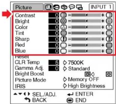
Description of Adjustment Items
| Selectable items | Press ◀ | Press ▶ |
| Contrast | For less contrast | For more contrast |
| Bright | For less brightness | For more brightness |
| Color | For less color intensity | For more color intensity |
| Tint | For making skin tones purplish | For making skin tones greenish |
| Sharp | For less sharpness | For more sharpness |
| Red | For weaker red | For stronger red |
| Blue | For weaker blue | For stronger blue |

Note
- "Color", "Tint" and "Sharp" do not appear for RGB input in INPUT 5 mode.
- Toreset all adjustment items, select "Reset" on the "Picture" menu screen and press 📄.
- "Tint" cannot be used with PAL, SECAM, PAL-M, PAL-N or PAL-60.
- "Color", "Tint" and "Sharp" cannot be used in the DIGITAL mode.
Adjusting the Color Temperature
This function allows for selecting the desired color temperature. With the lower value selected, the projected image becomes warmer, reddish and incandescent-like while with the higher value, the image becomes cooler, bluish and fluorescent-like.
Menu operation Page 40
Example: "Picture" menu screen for INPUT 1 mode
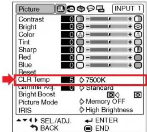
Description of Color Temperature Settings
| CLR Temp | Description |
| 5500K | The less the value is set to, the warmer, reddish, incandescent-like the image becomes. |
| 6500K | |
| 7500K | |
| 8500K | |
| 9300K | The more the value is set to, the cooler, bluish, fluorescent-like the image becomes. |
| 10500K |
"CLR Temp" is fine adjusted by following the procedure below.
1
Select "CLR Temp" in the "Picture" menu on the menu screen and press ⏻.
- A single menu bar of "CLR Temp" is displayed.
CLR Temp 5 7500K
2
Press ▲▲or ▼▼to fine adjust the color temperature.
- With the lower value selected, the projected image becomes magenta-tinged. With the higher value selected, the projected image becomes green-tinged.
- Pressing ◀ or ▶ changes the value of the color temperature in the sub menu.

Note
- Values on "CLR Temp" are only for general standard purposes.
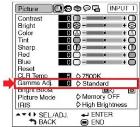
Gamma Correction Function
Gamma is an image quality enhancement function. Four gamma settings are available to allow for differences in the brightness of the room.
Menu operation ▶ Page 40
Example: "Picture" menu screen for INPUT 1 mode
Description of Gamma Modes
| Selectable Items | Description |
| Standard | Standard picture without gamma correction |
| Cinema 1 | Gives greater depth to darker portions of images. |
| Cinema 2 | Brightness is toned down and the image becomes more balanced. |
| Cinema 3 | Brighten the darker portions of images for easier viewing in a dimly lit room. |
"Gamma Adj." is fine adjusted by following the procedure below.
1
Select “Gamma Adj.” in the “Picture” menu on the menu screen and press ⏻.
- A single menu bar of "Gamma Adj." is displayed.
Gamma Adj. 0 Standard
2
Press ▲▲or ▼▼to fine adjust the color temperature.
- With the lower value selected, the projected image becomes less brightness. With the higher value selected, the projected image becomes more brightness.
- Pressing ◀ or ▶ changes the value of the Gamma in the sub menu.
Emphasising the Contrast
This function emphasises the bright portions of images to obtain a higher contrast image.
Menu operation ▶ Page 40
Example: "Picture" menu screen for INPUT 1 mode
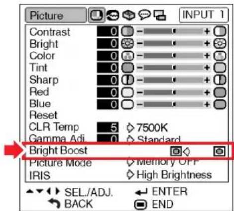
Description of Bright Boost settings
| Selectable Items | Description |
| (ON) | For emphasising the bright portions of images |
| (OFF) | For disabling “Bright Boost” |
Picture Mode Function
This function stores all items set in "Picture". Five settings can be stored separately in "Memory 1" to "Memory 5". Each stored setting is reassigned to each input mode (INPUT 1 to INPUT 5).
Even when the input mode or signal is changed, you can easily select optimal settings from the stored settings.
Menu operation Page 40
Example: "Picture" menu screen for INPUT 1 mode
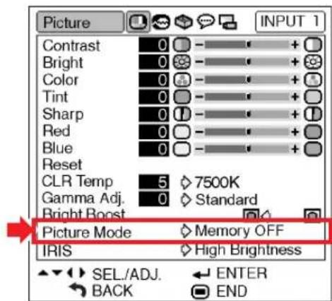
Select "Picture Mode" on the "Picture" menu and the memory location where you want to store the settings. Then adjust the setting items on the "Picture" menu.
| Picture Mode | Description |
| Memory 1-5 | Settings of all items in “Picture” can be stored for the respective input modes. The stored settings (Memory 1 to 5) can be selected in any input modes. |
| Memory OFF | Besides “Memory 1” to “Memory 5”, other settings on the “Picture” menu can be stored for each input mode. The settings stored in “Memory OFF” cannot be applied when another input mode is selected. |
If you want to apply the stored settings on the "Picture" menu, select input mode and then press 📄, or select "Picture Mode" in the "Picture" menu.
If you want to change the stored settings, select the memory location for those settings and make settings on the "Picture" menu.
Switching the High Brightness/High Contrast Mode
This function changes the brightness and contrast of the projected image. It can be operated using the IRIS button on the remote control.
Menu operation Page 40
Example: "Picture" menu screen for INPUT 1 mode
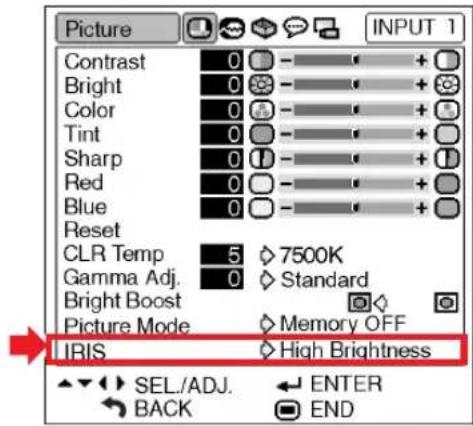
Description of IRIS Settings
| Selectable items | Description |
| High Brightness | High brightness is given priority over high contrast. |
| High Contrast | High contrast is given priority over high brightness. |
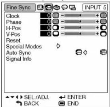
Computer Image Adjustment ("Fine Sync" menu)
You can adjust the computer image, match the computer display mode, and confirm the input signal using the "Fine Sync" menu.
Adjusting the Computer Image
Use the Fine Sync function in case of irregularities such as vertical stripes or flickering in portions of the screen.
Menu operation ▶ Page 38
Example: "Fine Sync" menu screen for INPUT 5 (RGB) mode
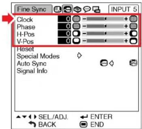
Description of Adjustment Items
| Selectable items | Description |
| Clock | Adjusts vertical noise. |
| Phase | Adjusts horizontal noise (similar to tracking on your VCR). |
| H-Pos | Centers the on-screen image by moving it to the left or right. |
| V-Pos | Centers the on-screen image by moving it up or down. |

Note
- You can automatically adjust the computer image by setting "Auto Sync" on the "Fine Sync" menu to "ON" (ON) or pressing ON the remote control. See page 46.
- "Clock", "Phase", "H-Pos" and "V-Pos" cannot be used in the DIGITAL mode.
- "Clock" and "Phase" cannot be used in the Component mode.
- The adjustable area of each item may be changed according to the input signal.
- Toreset all adjustment items, select "Reset" and press ⏻
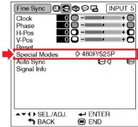
Special Modes Setting
Ordinarily, the type of input signal is detected and the correct resolution mode is automatically selected. However, for some signals, the optimal resolution mode in “Special Modes” on the “Fine Sync” menu may need to be selected to match the computer display mode.
Menu operation ▶ Page 40
Example: "Fine Sync" menu screen for INPUT 5 (Component) mode

Note
- If your computer displays patterns which repeat every other line (horizontal stripes), flickering may occur which makes the image hard to see.
- When inputting DTV 1080I signal, select the corresponding type of signal.
- See "Checking the Input Signal" on the next page for information on the currently selected input signal.
Note
Auto Sync Adjustment
Select whether the image is to be synchronized automatically when switching the signal with "ON" or "OFF".
Menu operation ▶ Page 40
Example: "Fine Sync" menu screen for INPUT 5 (RGB) mode
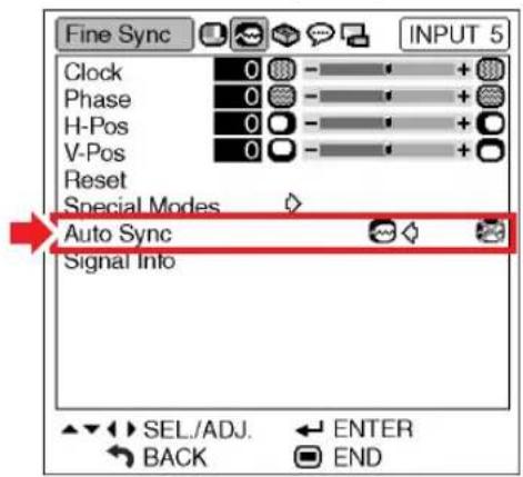
Description of Auto Sync Adjustment
| Selectable items | Description |
| (ON) | Auto Sync adjustment will occur when the projector is turned on or when the input signals are switched, when connected to a computer. |
| (OFF) | Auto Sync adjustment is not automatically performed. |

Note
- Auto Sync adjustment is also performed by pressing AUTO SYNC on the remote control.
- The Auto Sync adjustment may take some time to complete, depending on the image of the computer connected to the projector.
- When the optimum image cannot be achieved with Auto Sync adjustment, use manual adjustments. (See page 45.)
- "Auto Sync" cannot be used in the DIGITAL mode.
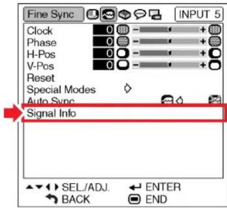
Checking the Input Signal
This function allows you to check the current input signal information.
Menu operation ▶ Page 40
Example: "Fine Sync" menu screen for INPUT 5 (RGB) mode

Note
- 540P is displayed on the screen when signal 1080I is inputted during DVI connection.
Using the "Options" Menu
You can use the "Options" menu to enhance the usage for the projector.
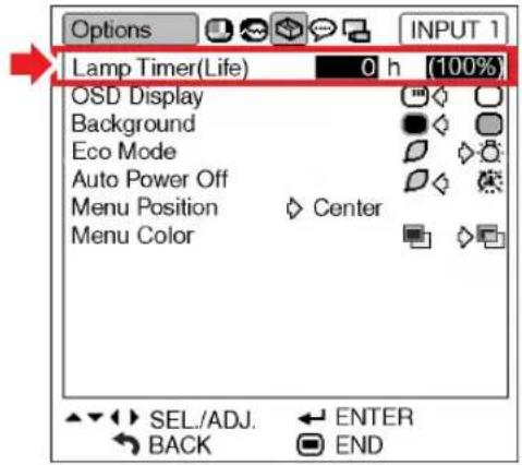
Checking the Lamp Life Status
You can confirm the cumulative lamp usage time and the remaining lamp life (percentage).
Menu operation ▶ Page 40
Example: "Options" menu screen for INPUT 1 mode
Description of Lamp Life
| Lamp usage condition | Remaining lamp life | ||
| “Life” | 100% 5% | ||
| Operated exclusivelyin Eco mode ( ) | Approx. Approx.3,000 hours 150 hours | ||
| Operated exclusivelyin Standard mode ( ) | Approx. Approx.2,000 hours 100 hours | ||

Note
- It is recommended that the lamp be changed when the remaining lamp life becomes 5%. (See page 56.)
- The table above indicates rough estimates in the case of using only in each mode shown.
- Remaining lamp life changes within the range of the values shown depending on the frequency at which "Eco Mode" is switched to "☐" (Eco mode) and "☐" (Standard mode). (See page 49.)
- The lamp life may vary depending on the usage condition.
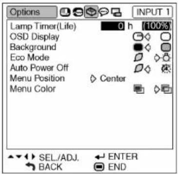
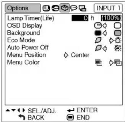
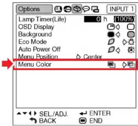
Setting On-screen Display
This function allows you to turn off the on-screen messages that appear during input select.
Menu operation Page 40
Example: "Options" menu screen for INPUT 1 mode
![Options Lamp Timer(Life) 0 h [100%] OSD Display Background Eco Mode Auto Power Off Menu Position Center Menu Color SEL./ADJ. ENTER BACK END](/content/2026/06/1175767/images/62c3e0dde02bc208ecedda9f18eea631afd49c0777c6f57cdca73b853b89b594.jpg)
Description of "OSD Display" Settings
| Selectable items | Description |
| (ON) | All On-screen Displays are displayed. |
| (OFF) | INPUT/AUTO SYNC/ “An invalid button has been pressed.” are not displayed. |
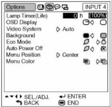
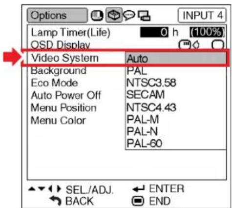
Setting the Video System
The video input system mode is factory preset to "Auto"; however, a clear picture from the connected audio-visual equipment may not be received, depending on the video signal difference. In that case, switch the video signal.
Menu operation Page 40
Example: "Options" menu screen for INPUT 4 mode
Description of Video Systems
| Selectable items | Description |
| PAL | When connected to PAL video equipment. |
| NTSC3.58 | When connected to NTSC video equipment. |
| SECAM | When connected to SECAM video equipment. |
| NTSC4.43 | When reproducing NTSC signals in PAL video equipment. |

Note
- The video signal can only be set in INPUT 3, INPUT 4 mode.
- "A uto" cannot be set for PAL-M and PAL-N input signals. Select "PAL-M" or "PAL-N" in "Video System" menu for PAL-M and PAL-N input signals.
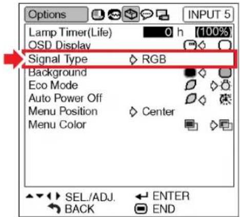
Signal Type Setting
This function allows you to select the input signal type RGB or Component for INPUT 5.
Menu operation ▶ Page 40
Example: "Options" menu screen for INPUT 5 (RGB) mode
Description of Signal Type Settings
| Selectable items | Description |
| RGB | Set when RGB signals are received. |
| Component | Set when Component signals are received. |

Note
- You can also select "Signal Type" using on the remote control (only INPUT 5).
Selecting a Background Image
This function allows you to select the image displayed when no signal is being sent to the projector.
Menu operation ▶ Page 40
Example: "Options" menu screen for INPUT 1 mode
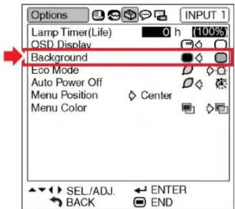
Description of Background Images
| Selectable items | Description |
| (Blue) | Blue screen |
| (None) | Black screen |
Eco Mode
Menu operation ▶ Page 40
Example: "Options" menu screen for INPUT 1 mode
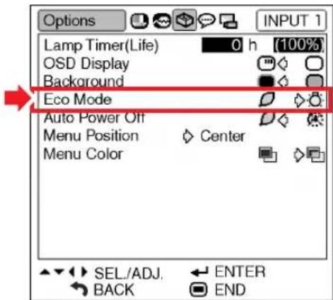
Description of Eco Mode
| Selectable items | Brightness | Power consumption(When using AC 100V) | Lamp life |
| (Eco mode) | 85% | 315 W | Approx.3,000 hours |
| (Standard mode) | 100% | 360 W | Approx.2,000 hours |
Note
- When "Eco Mode" is set to "☐" (Eco mode), the power consumption will decrease and the lamp life will extend. (Projection brightness decreases 15%.)
Auto Power Off Function
Menu operation ▶ Page 40
Example: "Options" menu screen for INPUT 1 mode
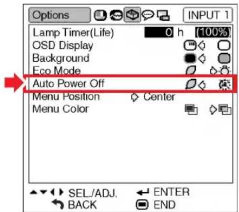
Description of Auto Power Off
| Selectable items | Description |
| (ON) | The projector automatically enters the standby mode when no input signal is detected for 15 minutes or longer. |
| (OFF) | The Auto Power Off function will be disabled. |

Note
- When the Auto Power Off function is set to “(ON), 5 minutes before the projector enters the standby mode, the message “Enter STANDBY mode in X min.” will appear on the screen to indicate the remaining minutes.
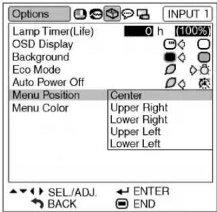
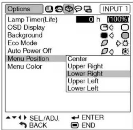
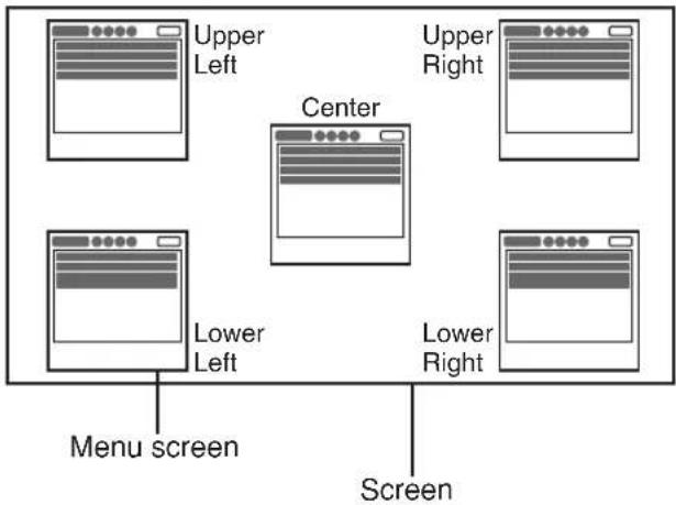
Selecting the Menu Screen Position
This function allows you to select the desired position of the menu screen.
Menu operation Page 40
Example: "Options" menu screen for INPUT 1 mode
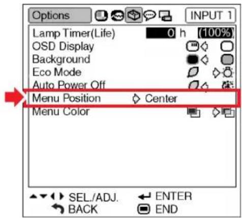
Description of Menu Positions
| Selectable items | Description |
| Center | Displayed on the center of the image. |
| Upper Right | Displayed on the upper right of the image. |
| Lower Right | Displayed on the lower right of the image. |
| Upper Left | Displayed on the upper left of the image. |
| Lower Left | Displayed on the lower left of the image. |
Position of the Menu Screen which Is Displayed on the Screen
flowchart
graph TD
    A["Window 1"] --> B["Center"]
    C["Window 2"] --> B
    D["Window 3"] --> B
    E["Window 4"] --> B
    F["Window 5"] --> B
    G["Window 6"] --> B
    H["Window 7"] --> B
    I["Window 8"] --> B
    J["Window 9"] --> B
    K["Window 10"] --> B
    L["Menu screen"] --> M["Screen"]
Selecting the Menu Color
This function allows you to select the color of the menu screen.
Menu operation ▶ Page 40
Example: "Options" menu screen for INPUT 1 mode
Description of Menu Colors
| Selectable Items | Description |
| (Opaque) | The menu is displayed opaquely. |
| (Translucent) | The menu is displayed translucently. The part of the menu on the image becomes transparent. |
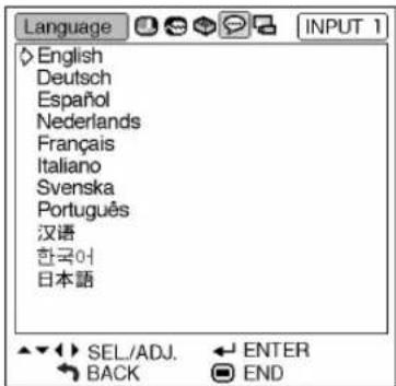
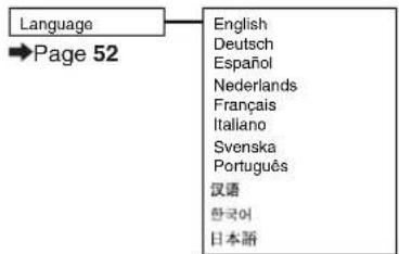
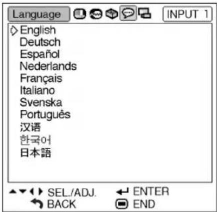
Selecting the On-screen Display Language and the Projection Mode
Selecting the On-screen Display Language
The projector can switch the on-screen display language among 11 languages: English, German, Spanish, Dutch, French, Italian, Swedish, Portuguese, Chinese, Korean or Japanese.
Example: "Language" menu screen for INPUT 1 mode
1

- The "Picture" menu will be displayed.
2
Press ◀ or ▶ to select the “Language” menu icon (💡).
- The "Language" menu will be displayed.
3
Press ▲ or ▼ to select the desired language, and then press ENTER
- The language you selected will be set as the on-screen display.
4
Press

- The "Language" menu will disappear.

Note
- This procedure can also be performed by using the buttons on the projector.
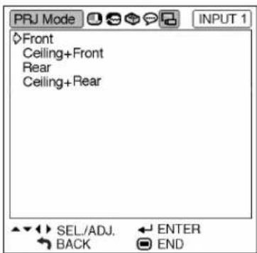
Setting the Projection Mode
This projector is equipped with a reverse/invert image function that allows you to reverse or invert the projected image for various applications.
Menu operation ▶ Page 40
Example: "PRJ Mode" menu screen
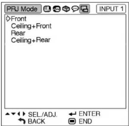
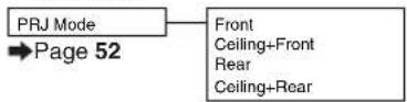
Description of PRJ Modes
| Selectable items | Description |
| Front | Normal image |
| Ceiling + Front | Inverted image |
| Rear | Reversed image |
| Ceiling + Rear | Reversed and inverted image |
Front

Ceiling + Front
Rear
Ceiling + Rear

Note
- This function is used for the reversed image and ceiling-mount setups. (See page 18.)
Maintenance
Cleaning the projector
■Ensure to unplug the power cord before cleaning the projector.
■The cabinet as well as the operation panel is made of plastic. Avoid using benzene or thinner, as these can damage the finish on the cabinet.
■Do not use volatile agents such as insecticides on the projector.
Do not attach rubber or plastic items to the projector for long periods.
The effects of some of the agents in the plastic may cause damage to the quality or finish of the projector.
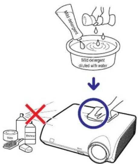
■Wipe off dirt gently with a soft flannel cloth.
■When the dirt is hard to remove, soak a cloth in a mild detergent diluted with water, wring the cloth well and then wipe the projector.
Strong cleaning detergents may discolor, warp or damage the coating on the projector. Make sure to test on a small, inconspicuous area on the projector before use.
Cleaning the lens
■Use a commercially available blower or lens cleaning paper (for glasses and camera lenses) for cleaning the lens. Do not use any liquid type cleaning agents, as they may wear off the coating film on the surface of the lens.
■As the surface of the lens can easily get damaged, ensure not to scrape or hit the lens.
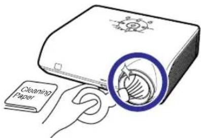
Cleaning the exhaust and intake vents
■Use a vacuum cleaner to clean dust from the exhaust vent and the intake vent.
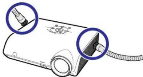
natural_image
Illustration of a medical device with two blue circular insets showing a screw and a cable inserted (no text or symbols)
Info
- If you want to clean the air vents of projector, ensure to press STANDBY on the projector or on the remote control and put the projector into standby mode. After the cooling fan has stopped, unplug the power cord from the AC socket and clean the vents.
Maintenance Indicators
■The warning lights on the projector indicate problems inside the projector.
If a problem occurs, either the temperature indicator or the lamp indicator will illuminate red, and the projector will enter the standby mode. After the projector has entered the standby mode, follow the procedures given below.
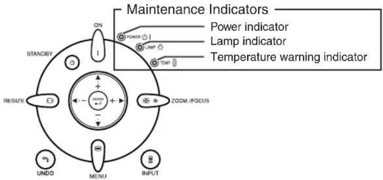
About the temperature warning indicator

TEMP.
If the temperature inside the projector increases, due to blockage of the air vents, or the setting location, "TEMP." will illuminate in the lower left corner of the picture. If the temperature keeps on rising, the lamp will turn off and the temperature warning indicator will blink, the cooling fan will run for a further 90 seconds, and then the projector will enter the standby mode. After "TEMP." appears, ensure to perform the measures described on page 55.
About the lamp indicator

Change The Lamp.
■When the remaining lamp life becomes 5% or less, “☒” (yellow) and “Change The Lamp.” will be displayed on the screen. When the percentage becomes 0%, it will change to “☒” (red), the lamp will automatically turn off and then the projector will automatically enter the standby mode. At this time, the lamp indicator will illuminate in red.
■ If you try to turn on the projector a fourth time without replacing the lamp, the projector will not turn on.
| Maintenance indicator | Problem | Cause Possible solution | ||
| Normal | Abnormal | |||
| Temperature warning indicator | Off | Red on (Standby) | The internal temperature is abnormally high. | • Blocked air intake |
| • Cooling fan break-down• Internal circuit failure• Clogged air intake | ||||
| Lamp indicator | Green on (Green blinks when the lamp is warming up or shutting down.) | Red on | The lamp does not illuminate. | — |
| Time to change the lamp. | • Remaining lamp life becomes 5% or less. | |||
| Red on (Standby) | The lamp does not illuminate. | • Burnt-out lamp• Lamp circuit failure | ||

Info
- If the temperature warning indicator illuminates and the projector enters the standby mode, check whether any of the ventilation holes are blocked (page 7) and then try turning the power back on. Wait until the projector has cooled down completely before plugging in the power cord and turning the power back on. (At least 10 minutes.)
- If the power is turned off for a brief moment due to power outage or some other cause while using the projector, and the power supply recovers immediately after that, the lamp indicator will illuminate in red and the lamp may not be lit. In this case, unplug the power cord from the AC outlet, replace the power cord in the AC outlet and then turn the power on again.
- Do not unplug the power cord after the projector has entered the standby mode and while the cooling fan is running. The cooling fan runs for about 90 seconds.
Lamp
It is recommended that the lamp (optional: AN-K2LP) be replaced when the remaining lamp life becomes 5% or less, or when you notice a significant deterioration in the picture and color quality. The lamp life (percentage) can be checked with the on-screen display. See page 47.
■ Purchase a replacement lamp of type AN-K2LP from your place of purchase, nearest Sharp Authorized Service Center or Dealer.
IMPORTANT NOTE TO U.S. CUSTOMERS:
The lamp included with this projector is backed by a 90-day parts and labor limited warranty. All service of this projector under warranty, including lamp replacement, must be obtained through an Sharp Authorized Service Center or Dealer. For the name of the nearest Sharp Authorized Service Center or Dealer, please call toll-free: 1-888-GO-SHARP (1-888-467-4277).
Hg LAMP CONTAINS MERCURY For State Lamp Disposal Information
www.lamprecycle.org or 1-800-BE-SHARP
U.S.A. ONLY
Caution Concerning the Lamp
This projector utilizes a pressurized mercury lamp. A loud sound may indicate lamp failure. Lamp failure can be attributed to numerous sources such as: excessive shock, improper cooling, surface scratches or deterioration of the lamp due to a lapse of usage time.
The period of time up to failure largely varies depending on the individual lamp and/or the condition and the frequency of use. It is important to note that failure can often result in the bulb cracking.
■ When the lamp replacement indicator and on-screen display icon are illuminated, it is recommended that the lamp be replaced with a new one immediately, even if the lamp appears to be operating normally.
■ Should the lamp break, the glass particles may spread inside the lamp cage or gas contained in the lamp may be vented into the room from the exhaust vent. Because the gas in this lamp includes mercury, ventilate the room well if the lamp breaks and avoid all exposure to the released gas. In case of exposure to the gas, consult a doctor as soon as possible.
■ Should the lamp break, there is also a possibility that glass particles may spread inside of the projector. In such a case, it is recommended you contact your nearest Sharp Authorized Service Center or Dealer to assure safe operation.
Replacing the Lamp

Caution
- Do not remove the lamp unit from the projector right after use. The lamp will be very hot and may cause burn or injury.
- Wait at least one hour after the power cord is disconnected to allow the surface of the lamp unit to fully cool before removing the lamp unit.
■ Carefully change the lamp by following the instructions described in this section. *If you wish, you may have the lamp replaced at your nearest Sharp Authorized Service Center or Dealer.
* If the new lamp does not light after replacement, take your projector to the nearest Sharp Authorized Service Center or Dealer for repair.
Removing and Installing the Lamp Unit

Warning!
- During projector operation, the lamp unit is very hot. Do not remove the lamp unit from the projector right after use. The lamp and parts around the lamp will be very hot and may cause burn or injury.

Info
- Ensure to remove the lamp unit using the handle. Ensure not to touch the glass surface of the lamp unit or the inside of the projector.
• To avoid injury to yourself and damage to the lamp, ensure to carefully follow the steps below. - Do not loosen other screws except for the lamp unit cover and lamp unit.
1
Press on the projector or on the remote control to put the projector into standby mode.
- Wait until the cooling fan stops.
2
Disconnect the power cord.
- Unplug the power cord from the AC socket.
- Leave the lamp until it has fully cooled down (about 1 hour).
3
Remove the lamp unit cover.
- Turn the projector over. Loosen the user service screw (①) that secures the lamp unit cover. Hold the tab and slide towards the direction of the arrow to remove the lamp unit cover (②).
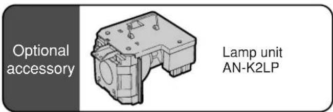
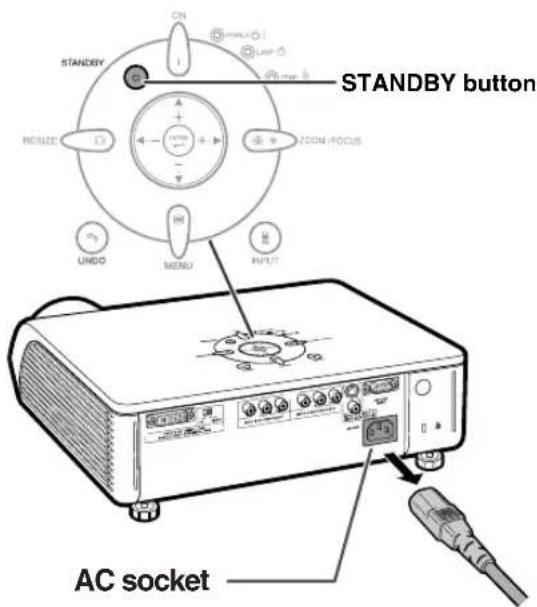
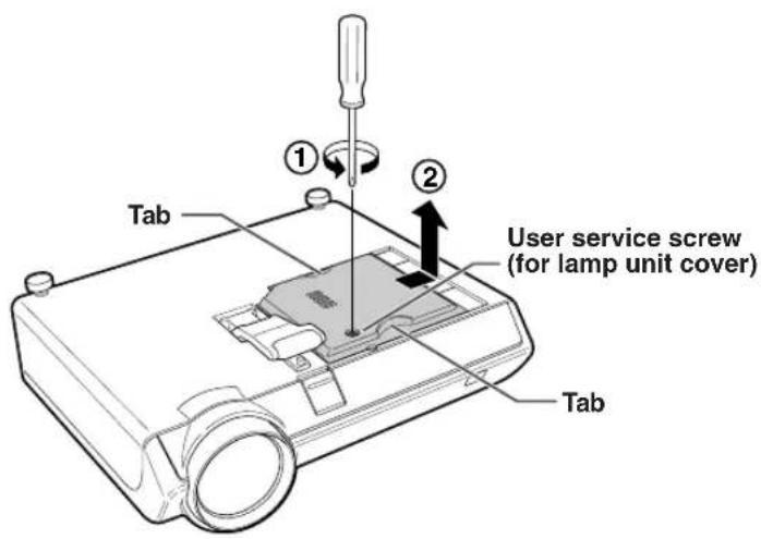
Regarding the Lamp
4 Remove the lamp unit.
- Loosen the two securing screws from the lamp unit. Hold the lamp unit by the handle and pull it in the direction of the arrow. At this time, keep the lamp unit horizontal and do not tilt it.
5 Insert the new lamp unit.
- Press the lamp unit firmly into the lamp unit compartment. Fasten the securing screws.
6 Replace the lamp unit cover.
- Align the lamp unit cover and slide it to close. Then tighten the user service screw to secure the lamp unit cover.

Info
- If the lamp unit and lamp unit cover are not correctly installed, the power will not turn on, even if the power cord is connected to the projector.
Resetting the Lamp Timer
Reset the lamp timer after replacing the lamp.

Info
- Make sure to reset the lamp timer only when replacing the lamp. If you reset the lamp timer and continue to use the same lamp, this may cause the lamp to become damaged or explode.
1 Connect the power cord.
- Plug the power cord into the AC socket of the projector.
2 Reset the lamp timer.
- Press ⏻, INPUT ⏻, UNDO ◀, and ▶ on the projector in order, and then press ⏻ on the projector.
- "LAMP 0000H" is displayed on the lower left of the screen, indicating that the lamp timer is reset.
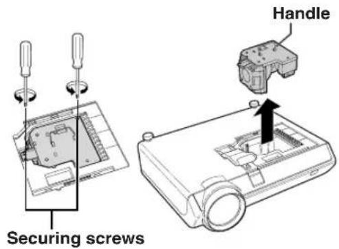
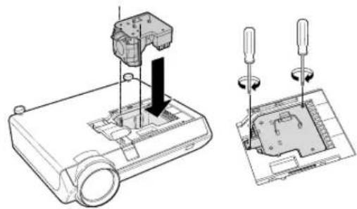
natural_image
Technical line drawing showing a device with a mounted component and a close-up of its internal components (no text or symbols)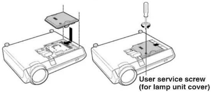
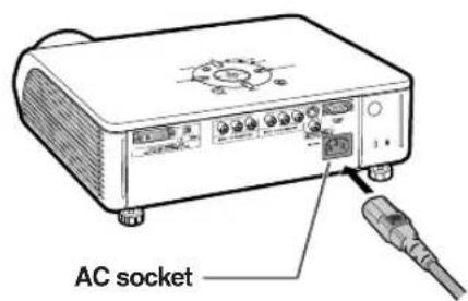
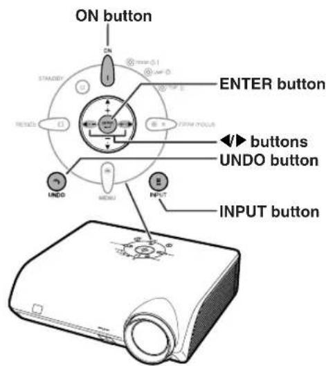
Connecting Pin Assignments
DVI-I (INPUT 5) port : 29 pin connector
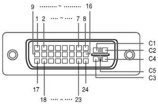
• DVI Digital INPUT
Pin No. Signal Pin No. Signal
| 1 | T | .M.D.S data 2- 16 Hot plug detection |
| 2 | T | .M.D.S data 2+ 17 T.M.D.S data 0- |
| 3 | T | .M.D.S data 2 shield 18 T.M.D.S data 0+ |
| 4 Not connected 19 T.M.D.S data 0 shield | ||
| 5 Not connected 20 Not connected | ||
| 6 DDC clock 21 Not connected | ||
| 7 DDC data 22 T.M.D.S clock shield | ||
| 8 Not connected 23 T.M.D.S clock+ | ||
| 9 | T | .M.D.S data 1- 24 T.M.D.S clock- |
| 10 T.M.D.S data 1+ C1 Not connected | ||
| 11 T.M.D.S data 1 shield | C2 Not connected | |
| 12 Not connected | C3 Not connected | |
| 13 Not connected | C4 Not connected | |
| 14 +5V power | C5 Ground | |
| 15 Ground | ||
• DVI Analog RGB Input
| Pin No. Signal | Pin No. Signal |
| 1 Not connected | 16 Hot plug detection |
| 2 Not connected | 17 Not connected |
| 3 Not connected | 18 Not connected |
| 4 Not connected | 19 Not connected |
| 5 Not connected | 20 Not connected |
| 6 DDC clock 21 Not connected | |
| 7 DDC data | 22 Not connected |
| 8 Vertical sync | 23 Not connected |
| 9 Not connected | 24 Not connected |
| 10 Not connected | C1 Analog input Red |
| 11 Not connected | C2 Analog input Green |
| 12 Not connected | C3 Analog input Blue |
| 13 Not connected | C4 Horizontal sync |
| 14 +5V power | C5 Ground |
| 15 Ground | |
• DVI Analog Component Input
| Pin No. Signal | Pin No. Signal |
| 1 Not connected | 16 Not connected |
| 2 Not connected | 17 Not connected |
| 3 Not connected | 18 Not connected |
| 4 Not connected | 19 Not connected |
| 5 Not connected | 20 Not connected |
| 6 Not connected | 21 Not connected |
| 7 Not connected | 22 Not connected |
| 8 Not connected | 23 Not connected |
| 9 Not connected | 24 Not connected |
| 10 Not connected | C1 Analog input PR/CR |
| 11 Not connected | C2 Analog input Y |
| 12 Not connected | C3 Analog input PB/CB |
| 13 Not connected | C4 Not connected |
| 14 Not connected | C5 Ground |
| 15 Ground |
Computer Compatibility Chart
The table below lists signal codes that are compatible with the projector. When the images are distorted or cannot be projected, adjust the output signal of your computer and so forth while referring to the table below.
Computer
• Horizontal Frequency: 15–70 kHz
Vertical Frequency: 43–75 Hz
Pixel Clock: 12–80 MHz
Compatible with sync on green
XGA compatible in intelligent compression
| PC/MAC/WS | Resolution | Horizontal Frequency (kHz) | Vertical Frequency (Hz) | VESA Standard | DVI Support | Display | |
| PC | VGA | 640 × 350 | 27.0 60 | Upscale | |||
| 31.5 70 | |||||||
| 720 × 350 | 27.0 60 | ||||||
| 31.5 70 | |||||||
| 640 × 400 | 27.0 60 | ||||||
| 31.5 70 | |||||||
| 720 × 400 | 27.0 | 60 | |||||
| 31.5 | 70 | ||||||
| 640 × 480 | 26.2 | 50 | ✓ | ||||
| 31.5 | 60 | ✓ | ✓ | ||||
| 34.7 | 70 | ✓ | |||||
| 37.9 | 72 | ✓ | ✓ | ||||
| 37.5 | 75 | ✓ | ✓ | ||||
| SVGA | 800 × 600 | 31.4 50 | ✓ | ||||
| 35.1 56 | ✓ | ✓ | |||||
| 37.9 60 | ✓ | ✓ | |||||
| 44.5 70 | ✓ | ||||||
| 48.1 72 | ✓ | ✓ | |||||
| 46.9 75 | ✓ | ✓ | |||||
| XGA | 1,024 × 768 | 35.5 43 | ✓ | ✓ | Intelligent Compression | ||
| 40.3 50 | ✓ | ||||||
| 56.5 70 | ✓ | ✓ | |||||
| 58.1 72 | ✓ | ||||||
| — | 1,280 × 720 | 45.0 60 | ✓ | ||||
| PC/MAC 13* | VGA | 640 × 480 | 34.9 67 | Upscale | |||
| MAC 16* | SVGA | 832 × 624 | 46.8 75 | ||||
| 49.6 75 | |||||||
| PC/MAC 19* | XGA | 1,024 × 768 | 48.4 60 | ✓ | Intelligent Compression | ||
| 60.0 | 75 | ✓ | |||||

Note
- This projector may not be able to display images from notebook computers in simultaneous (CRT/LCD) mode. Should this occur, turn off the LCD display on the notebook computer and output the display data in "CRT only" mode. Details on how to change display modes can be found in your notebook computer's operation manual.
DTV
| Signal Vertical Frequency (Hz) | Horizontal Frequency (kHz) | |
| 480I | 15.7 | 60 |
| 480P | 31.5 | 60 |
| 540P | 33.8 | 60 |
| 576I | 15.6 | 50 |
| 576P | 31.3 | 50 |
| 720P | 45.0 | 60 |
| 1035I | 28.1 | 50 |
| 1035I | 33.8 | 60 |
| 1080I | 28.1 | 50 |
| 1080I | 33.8 | 60 |
Troubleshooting
| Problem | Check | Page |
 No picture No picture | Projector power cord is not plugged into the wall outlet. | 27 |
| Power to the external connected devices is off. | — | |
| The selected input mode is wrong. | 29 | |
| Cables are incorrectly connected to the rear panel of the projector. | 19-26 | |
| External output has not been set when connecting notebook computer. | — | |
| “Contrast” and “Bright” are set to minimum position. | 42 | |
 Color is faded or poor. Color is faded or poor. | Image adjustments are incorrectly set. | 42 |
| (Video Input only)Video input system is incorrectly set.(INPUT 5)Input signal type (RGB/Component) is incorrectly set. | 4848 | |
| On-screen display does not appear. | “OSD Display” is set to “OFF”. | 47 |
 Picture is blurred;noise appears. Picture is blurred;noise appears. | Adjust the focus. | 30 |
| The projection distance exceeds the focus range. | 17 | |
| (Computer Input only)Perform “Fine Sync” Adjustments. (“Clock” Adjustment)Perform “Fine Sync” Adjustments. (“Phase” Adjustment)Noise may appear depending on the computer. | 4545— | |
| An unusual sound is occasionally heard from the cabinet. | If the picture is normal, the sound is due to cabinet shrinkage caused by room temperature changes. This will not affect operation or performance. | — |
| Maintenance indicator illuminates or blinks in red. | See “Maintenance Indicators”. | 54 |
| The cooling fan becomes noisy. | When temperature inside the projector increases, the cooling fan runs faster. | — |
| The lamp takes a long time to turn on. | The lamp will eventually need to be changed.The lamp has reached the end of its life. Replace the lamp. | 57 |
| Picture is dark. | ||
| Image is green on INPUT 5 Component.Image is pink (no green) on INPUT 5 RGB. | Change the input signal type. | 48 |
This projector is equipped with a microprocessor. Its performance could be adversely affected by incorrect operation or interference. If this should happen, unplug the Unit and plug it in again after more than 5 minutes.
Service Information (For the U.S.)
For the location of the nearest Sharp Authorized Service Center, or to obtain product literature, accessories, supplies or customer assistance, please call 1-800-BE-SHARP (1-800-237-4277) or visit SHARP's website (http://www.sharpusa.com).
Specifications
| Product type | Projector |
| Model | DT-400 |
| Video system | PAL/PAL 60/PAL-M/PAL-N/SECAM/NTSC 3.58/NTSC 4.43DTV 480I/480P/720P/1080I |
| Display method | Single Panel Digital Micromirror Device (DMDTM) by Texas Instruments |
| DLP panel | Panel size: 0.8"Drive method: Digital Light Processing (DLPTM)No. of dots: 921,600 dots (1,280 [H] × 720 [V]) |
| Lens | 1-1.5 × zoom lens, F2.0-2.5 f=21.3-31.6 mm |
| Projection lamp | 275 W DC lamp |
| Video input signal | RCA Connector: VIDEO (INPUT 4), composite video, 1.0 Vp-p, sync negative, 75 Ω terminated |
| S-video input signal | 4-pin Mini DIN connector (INPUT 3)Y (luminance signal): 1.0 Vp-p, sync negative, 75 Ω terminatedC (chrominance signal): Burst 0.286 Vp-p, 75 Ω terminated |
| Component input signal | RCA Connector |
| (INPUT 1, 2) | Y: 1.0 Vp-p, sync negative, 75 Ω terminatedPb (Cb): 0.7 Vp-p, 75 Ω terminatedPr (Cr): 0.7 Vp-p, 75 Ω terminated |
| Analog RGB/Digital(INPUT 5/DIGITAL) | 29-pin DVI-I terminal |
| Input impedance 50 ΩInput level 250-1000 mV | |
| Input impedance 75 ΩInput level 0.7 Vp-pY: 1.0 Vp-p, sync negative, 75 Ω terminatedPb (Cb): 0.7 Vp-p, 75 Ω terminatedPr (Cr): 0.7 Vp-p, 75 Ω terminated | |
| Separate sync/Composite syncInput level TTL levelInput impedance 1 KΩGreen on syncInput level (Synchronizing input) 0.286 Vp-pInput impedance 75 Ω | |
| Horizontal resolution | 720 TV lines (DTV 720P input) |
| Pixel clock | 12-80 MHz |
| Vertical frequency | 43-75 Hz |
| Horizontal frequency | 15-70 kHz |
| Rated voltage | AC 100-240 V |
| Input current | 3.65 A (When using AC 100 V) |
| Rated frequency | 50/60 Hz |
| Power consumption | 360 W (When using AC 100 V) |
| Power consumption (standby) | 6 W (When using AC 100 V) |
| Heat dissipation | 1,350 BTU/hour |
| Operating temperature | 41°F to 95°F (+5°C to +35°C) |
| Storage temperature | -4°F to 140°F (-20°C to +60°C) |
| Cabinet | Plastic |
| I/R carrier frequency | 38 kHz |
| Dimensions (approx.) | 12 7/32" × 3 33/64" × 11 7/64" (310 (W) × 89 (H) × 282 (D) mm) |
| Weight (approx.) | 9.5 lbs. (4.3 kg) |
| Supplied accessories | Remote control, Two AA size batteries, Power cord, Lens cap (attached on the body), Operation manual |
| Replacement parts | Lamp unit (Lamp/cage module) (AN-K2LP), Remote control (RRMCGA334WJSA), AA size batteries, Power cord (QACCDA007WJPZ), Lens cap (PCAPHA021WJSA), Operation manual (TINS-B532WJZZ) |
As a part of policy of continuous improvement, SHARP reserves the right to make design and specification changes for product improvement without prior notice. The performance specification figures indicated are nominal values of production units. There may be some deviations from these values in individual units.
Dimensions
Units: inches (mm)
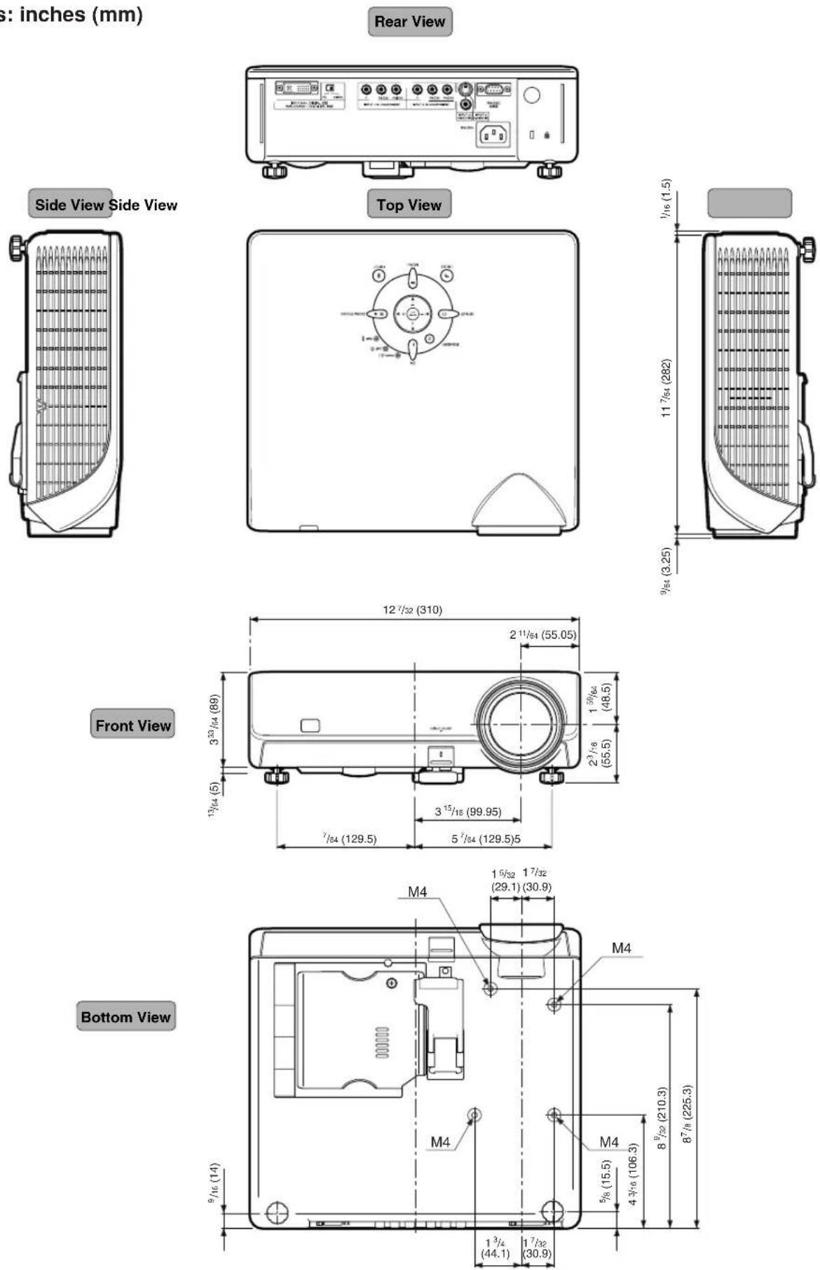
Aspect Ratio
Width and height ratio of an image. The normal aspect ratio of a computer and video image is 4:3. There are also wide images with an aspect ratio of 16:9 and 21:9.
Auto Sync
Optimizes projected computer images by automatically adjusting certain characteristics.
Background
Initial setting image projected when no signal is being output.
Clock
Clock adjustment is used to adjust vertical noise when clock level is incorrect.
CLR Temp (Color temperature)
Function that can be used to adjust the color temperature to suit the type of image input to the projector. Decrease the color temperature to create warmer, reddish images for natural flesh tones, or increase to create cooler, bluish images for a brighter picture.
Composite sync
Signal combining horizontal and vertical sync pulses.
DVI (Digital Visual Interface)
Display digital interface that also supports analog interfaces.
Gamma
Image quality enhancement function that offers a richer image by brightening the darker portions of the image without altering the brightness of the brighter portions. You can select from four different modes: Standard, Cinema 1, Cinema 2 and Cinema 3.
Intelligent compression and expansion
High quality resizing of lower and higher resolution images to fit the projector's native resolution.
Keystone Correction
Function to digitally correct a distorted image when the projector is set up at an angle, smoothes out jaggies on keystone images and compresses the image not only horizontally but vertically keeping the 16 : 9 aspect ratio.
Phase
Phase shift is a timing shift between isomorphic signals with the same resolution. When phase level is incorrect, the projected image typically displays horizontal flicker.
Resize
Allows you to modify or customize the picture display mode to enhance the input image. You can select from four different modes: STRETCH, SIDE BAR, SMART STRETCH and CINEMA ZOOM.
Stretch
Mode that stretches the 4:3 image horizontally to display it on the wide screen.
A
AC socket 27
Adjustment buttons 38
Aspect ratio 35
Auto Power Off 50
Auto Sync 46
AUTO SYNC button 46
B
Background 49
Blue 42
Bright 42
Bright Boost 43
C
Ceiling+Front 52
Ceiling+Rear 52
Clock 45
CLR Temp (Color Temperature) 42
Color 42
Component terminals 21
Contrast....42
D
DIGITAL INPUT button 29
DVI 22,23,25,26
E
Eco Mode 49
ENTER button 39
Exhaust vent 7,11,53
F
Fine Sync 45
Front 52
G
Gamma Adj. 43
H
HEIGHT ADJUST button.... 31
H-Pos 45
1
INPUT buttons 29
Intake vent 7,53
IRIS 34,44
IRIS button 34
K
Kensington Lock 11
KEYSTONE button 32
Keystone Correction 32
L
Lamp 56
Lamp indicator 54
Lamp Timer (Life) 47
Language 52
Lens cap....9
M
MENU button 38
Menu Color 51
Menu Position 50
0
ON button 27
On-screen display language 52
OSD Display 47
P
Phase 45
Picture 42
Picture Mode 44
PICTURE MODE button 34
Power cord 27
Power indicator....10
PRJ mode 52
R
Rear 52
Rear adjustment feet 31
Red 42
Remote control 12
Remote control sensor 13
Replacing the lamp 56
RESIZE button 34
S
Sharp 42
Signal Info 46
Signal Type 48
Special Modes 45
STANDBY button 28
STRETCH 35
S-video input terminal 24
T
Temperature warning indicator 54
Tint 42
U
UNDO button 34
V
Video input terminal 24
Video System 48
V-Pos 45
Z
ZOOM/FOCUS button 30
CONSUMER LIMITED WARRANTY
SHARP ELECTRONICS CORPORATION warrants to the first consumer purchaser that this Sharp brand product (the "Product"), when shipped in its original container, will be free from defective workmanship and materials, and agrees that it will, at its option, either repair the defect or replace the defective Product or part thereof with a new or remanufactured equivalent at no charge to the purchaser for parts or labor for the period(s) set forth below.
This warranty does not apply to any appearance items of the Product nor to the additional excluded item(s) set forth below nor to any Product the exterior of which has been damaged or defaced, which has been subjected to improper voltage or other misuse, abnormal service or handling, or which has been altered or modified in design or construction.
In order to enforce the rights under this limited warranty, the purchaser should follow the steps set forth below and provide proof of purchase to the servicer.
The limited warranty described herein is in addition to whatever implied warranties may be granted to purchasers by law. ALL IMPLIED WARRANTIES INCLUDING THE WARRANTIES OF MERCHANTABILITY AND FITNESS FOR USE ARE LIMITED TO THE PERIOD(S) FROM THE DATE OF PURCHASE SET FORTH BELOW. Some states do not allow limitations on how long an implied warranty lasts, so the above limitation may not apply to you.
Neither the sales personnel of the seller nor any other person is authorized to make any warranties other than those described herein, or to extend the duration of any warranties beyond the time period described herein on behalf of Sharp.
The warranties described herein shall be the sole and exclusive warranties granted by Sharp and shall be the sole and exclusive remedy available to the purchaser. Correction of defects, in the manner and for the period of time described herein, shall constitute complete fulfillment of all liabilities and responsibilities of Sharp to the purchaser with respect to the Product, and shall constitute full satisfaction of all claims, whether based on contract, negligence, strict liability or otherwise. In no event shall Sharp be liable, or in any way responsible, for any damages or defects in the Product which were caused by repairs or attempted repairs performed by anyone other than an authorized servicer. Nor shall Sharp be liable or in any way responsible for any incidental or consequential economic or property damage. Some states do not allow the exclusion of incidental or consequential damages, so the above exclusion may not apply to you.
THIS WARRANTY GIVES YOU SPECIFIC LEGAL RIGHTS. YOU MAY ALSO HAVE OTHER RIGHTS WHICH VARY FROM STATE TO STATE.
Model Specific Section (In-Home Service)
| Your Product Model Number & Description: | DT-400 Projector(Be sure to have this information available when you need service for your Product.) |
| Warranty Period for this Product: | One (1) year parts and labor from date of purchase except for the Projector Lamp for which the warranty period is ninety (90) days from date of purchase. After the ninety (90) day warranty period on the Projector Lamp, parts and labor for a lamp replacement are the responsibility of the consumer. |
| Additional Item(s) Excluded from Warranty Coverage (if any): | Cleaning of Optical System and/or replacement of any filter.Labor & materials required to remove and reinstall a suspended projector in installations not accessible with a standard (8' step) ladder or ceilings exceeding 12' in height.Labor & materials required to remove and reinstall a projector in complex systems including, but not limited to, projectors installed in custom enclosures, projectors connected to third party control and automation systems, and realignment of projectors installed in "mirrored" rear projection enclosures. |
| Where to Obtain Service: | From a Sharp Authorized Servicer located in the United States. To find the location of the nearest Sharp Authorized Servicer, call Sharp toll free at 1-800-BE-SHARP. |
| What to do to Obtain Service: | Contact your Sharp Authorized Servicer to obtain in-home service for this Product. The Servicer will come to your home and if necessary to remove the Product for repair at the Servicer's facility, the Servicer will reinstall it upon completion of repair. Be sure to have Proof of Purchase available. |
SHARP®
LIMITED WARRANTY
Consumer Electronics Products
Congratulations on your purchase!
Sharp Electronics of Canada Ltd. (hereinafter called "Sharp") gives the following express warranty to the first consumer purchaser for this Sharp brand product, when shipped in its original container and sold or distributed in Canada by Sharp or by an Authorized Sharp Dealer:
Sharp warrants that this product is free, under normal use and maintenance, from any defects in material and workmanship. If any such defects should be found in this product within the applicable warranty period, Sharp shall, at its option, repair or replace the product as specified herein.
This warranty shall not apply to:
(a) Any defects caused or repairs required as a result of abusive operation, negligence, accident, improper installation or inappropriate use as outlined in the owner's manual.
(b) Any Sharp product tampered with, modified, adjusted or repaired by any party other than Sharp, Sharp's Authorized Service Centres or Sharp's Authorized Servicing Dealers.
(c) Damage caused or repairs required as a result of the use with items not specified or approved by Sharp, including but not limited to head cleaning tapes and chemical cleaning agents.
(d) Any replacement of accessories, glassware, consumable or peripheral items required through normal use of the product including but not limited to earphones, remote controls, AC adapters, batteries, temperature probe, stylus, trays, filters, belts, ribbons, cables and paper.
(e) Any cosmetic damage to the surface or exterior that has been defaced or caused by normal wear and tear.
(f) Any damage caused by external or environmental conditions, including but not limited to transmission line/power line voltage or liquid spillage.
(g) Any product received without appropriate model, serial number and CSA/cUL markings.
(h) Any products used for rental or commercial purposes.
(i) Any installation, setup and/or programming charges.
Should this Sharp product fail to operate during the warranty period, warranty service may be obtained upon delivery of the Sharp product together with proof of purchase and a copy of this LIMITED WARRANTY statement to an Authorized Sharp Service Centre or an Authorized Sharp Servicing Dealer. In home warranty service may be provided at Sharp's discretion on any Sharp television with the screen size of 27" or larger and on any Sharp Over The Range Microwave Oven.
This warranty constitutes the entire express warranty granted by Sharp and no other dealer, service centre or their agent or employee is authorized to extend, enlarge or transfer this warranty on behalf of Sharp. To the extent the law permits, Sharp disclaims any and all liability for direct or indirect damages or losses or for any incidental, special or consequential damages or loss of profits resulting from a defect in material or workmanship relating to the product, including damages for the loss of time or use of this Sharp product or the loss of information. The purchaser will be responsible for any removal, reinstallation, transportation and insurance costs incurred. Correction of defects, in the manner and period of time described herein, constitute complete fulfillment of all obligations and responsibilities of Sharp to the purchaser with respect to the product and shall constitute full satisfaction of all claims, whether based on contract, negligence, strict liability or otherwise.
WARRANTY PERIODS
Projector 1 year (bulb 90 days)
To obtain the name and address of the nearest Authorized Sharp Service Centre or Dealer, please contact:
SHARP ELECTRONICS OF CANADA LTD.
SHARP ELECTRONICS OF CANADA LTD.
335 Britannia Road East
Mississauga, Ontario
L4Z 1W9
(905) 568-7140
Web site: www.sharp.ca