RG04524KNSX - Generator Generac - Free user manual and instructions
Find the device manual for free RG04524KNSX Generac in PDF.

| Product Type | Standby Generator |
| Brand | Generac |
| Model | RG04524KNSX |
| Power Output (Standby) | 45 kW |
| Power Output (Running) | 40 kW |
| Fuel Type | Natural Gas / Liquid Propane |
| Voltage | 240/120 V |
| Phase | Single Phase |
| Engine Type | Generac G-Force 4-Cylinder |
| Cooling System | Liquid Cooled |
| Starting System | Electric Start with Auto Transfer Switch |
| Dimensions (L x W x H) | 48 x 30 x 36 in |
| Weight | 520 lbs |
| Noise Level | 67 dBA at 23 ft |
| Warranty | 5-Year Limited Warranty |
| Main Functions | Automatic standby power, remote monitoring, exercise cycle |
| Maintenance Intervals | Oil change every 100 hours, air filter annually |
| Safety Features | Low oil shutdown, over-speed protection, overload protection |
| Parts Availability | Widely available through Generac dealers and online |
| Repairability | Modular design, serviceable with standard tools |
Frequently Asked Questions - RG04524KNSX Generac
User questions about RG04524KNSX Generac
0 question about this device. Answer the ones you know or ask your own.
Ask a new question about this device
Download the instructions for your Generator in PDF format for free! Find your manual RG04524KNSX - Generac and take your electronic device back in hand. On this page are published all the documents necessary for the use of your device. RG04524KNSX by Generac.
USER MANUAL RG04524KNSX Generac
Spark-Ignited Stationary Generators
Residential and Commercial

natural_image
Line drawing of a rectangular industrial machine with heat exchangers and cooling fans (no text or symbols)22 kW 2.4L
25 kW 1.5L
27 kW 2.4L
30 kW 1.5L
32 kW 2.4L
36 kW 2.4L
38 kW 2.4L
45 kW 2.4L
48 kW 5.4L
60 kW 2.4L

WARNING
Loss of life. This product is not intended to be used in a critical life support application. Failure to adhere to this warning could result in death or serious injury. (000209b)
Register your Generac product at:
WWW.GENERAC.COM
1-888-GENERAC
(888-436-3722)
Para español, visita: http://www.generac.com/service-support/product-support-lookup
Pour le français, visiter : http://www.generac.com/service-support/product-support-lookup
SAVE THIS MANUAL FOR FUTURE REFERENCE
Use this page to record important information about the generator set.
For quick and easy reference, copy the information printed on the Unit Identification Label onto the sample label printed here. The Unit Identification Label is located on the base frame adjacent to the front engine mount on all models.
When contacting an Independent Authorized Service Dealer (IASD) about parts and/or service, always provide the complete model number and serial number.
Operation and Maintenance: Proper maintenance and care of the generator ensures safe operation and longer service life while also keeping operating expenses to a minimum. It is the operator's responsibility to perform all safety checks, to make sure that all maintenance is performed promptly, and to have the equipment checked periodically by an Independent Authorized Service Dealer.
Normal maintenance, service and replacement of parts are the responsibility of the owner/operator, and are not considered defects in materials or workmanship within the terms of the warranty. Individual operating habits and usage may contribute to the need for additional maintenance or service.
When the generator requires servicing or repairs, contact an Independent Authorized Service Dealer for assistance. Authorized service technicians are factory-trained and are capable of handling all service needs.
When the generator requires servicing or repairs, the manufacturer recommends contacting an Independent Authorized Service Dealer for assistance. Authorized service technicians are factory-trained and are capable of handling all service needs. To locate the nearest Independent Authorized Service Dealer, please visit the dealer locator at:
www.honeywellgenerators.com/find-a-dealer
INDEPENDENT AUTHORIZED SERVICE DEALER LOCATION
To locate the nearest INDEPENDANT AUTHORIZED SERVICE DEALER, please call this number: 1-800-333-1322
or visit the dealer locator at:
www.generac.com/Service/DealerLocator/
GENERATOR UNIT
GEN MODEL:
MODEL:
SERIAL:
ALTERNATE
PROD DATE:
COUNTRY OF ORIGIN:
GENERATOR DATA
KW KVA HZ PF
UPSIZE ALT KW KVA
VOLT / AMP
ENG RPM ALT RPM
BREAKER KW AMP
X'D X''D
ROTOR STATOR CLASS
WINDINGS @ AMBIENT TEMP
003564
Figure 1-1. Sample Label
! WARNING
CANCER AND REPRODUCTIVE HARM
www.P65Warnings.ca.gov.
(000393a)
Table of Contents
Section 1: Safety
Introduction ....1
Read This Manual Thoroughly ....1
Safety Rules ....1
How to Obtain Service ....2
General Hazards ......2
Exhaust Hazards ....3
Fire Hazards ....3
Electrical Hazards ....3
Explosion Hazards ....3
Battery Hazards 4
Section 2: General Information
Emissions ....5
Emissions Data Plate ....5
Specifications 6
Engine Oil Recommendations ....8
Weather and Maintenance Kits ....8
Coolant Water Treatment 8
Fuel Requirements 8
Reconfiguring the Fuel System 9
Fuel Conversion Procedure from NG to LPV .....9
Change Fuel Selection ....10
Battery Requirements 10
Battery Charger 10
Battery Safety Precautions ......10
Corrosion Protection ....11
Section 3: Activation and Startup
Orientation ....13
Remove Side Access Panels ....13
Install Battery 13
Open Viewing Window 14
Activate Unit 15
Start and Run Engine ....16
Operational Checks 16
Self Test 16
Check Manual Transfer Switch Operation ....17
Electrical Checks 17
Test Generator Under Load 17
Test Auxiliary Shutdown Switch Operation ....18
Check Automatic Operation 18
Securing the Generator 19
Section 4: Operation
Control Panel 21
Auto/Manual/Off 21
Menu Navigation 22
Alarm/Warning Conditions 24
Change Time and Date 24
Programmable Timers 24
Dealer Programmable 24
User Programmable 24
USB Port for Firmware Updates 24
Battery Charger 25
Transfer Switch Automatic Operation ...... 25
Automatic Sequence of Operation ....25
Transfer Switch Manual Operation 26
Transfer to Generator Power 26
Transfer Back to Utility Power 27
Section 5: Maintenance
Component Locations 29
Access Panels 30
Removal 30
Installation 30
Maintenance 30
Service Maintenance Schedule ....31
Remove From Service 31
30 Hour Break-In 32
Daily Maintenance 32
Schedule A Maintenance 32
Schedule A Maintenance Item Locations 33
Preliminary Instructions 33
Check Enclosure Louvers ....33
Check Fuel Lines ....33
Check Coolant Level and Hoses ....33
Check Radiator for Clogging ....34
Check Lubricating Oil Level and Drain Hose .... 34
Replace Lubricating Oil and Oil Filter 35
Check Battery Condition/Fluid Level 38
Check and Adjust Accessory/Drive Belt 39
Replace Air Filter Element 41
Final Instructions 41
Schedule B Maintenance ....41
Schedule B Maintenance Item Locations 41
Drain/Flush Coolant System 42
Clean/Gap/Replace Spark Plugs 43
Final Instructions 43
Schedule C Maintenance 44
Return To Service 44
Lube Oil Maintainer System ....44
Description 44
Fill Oil Supply Tank 44
Test Functionality 45
Shutoff Valve 45
Section 6: Troubleshooting
Engine Troubleshooting ....47
Controller Troubleshooting ....48
Removal From Service During Utility Outages ... 49
Storage 49
Prepare For Storage 49
Return From Storage 50
Attention After Submersion ....50
Section 1: Safety
Introduction
Thank you for purchasing this stationary automatic standby generator set. Every effort was made to ensure that the information in this manual was both accurate and complete at the time it was released. However, the manufacturer reserves the right to change, alter or otherwise improve this product at any time without prior notice.
This generator is designed to automatically supply electrical power to operate critical loads during a utility power failure. The unit is factory installed in an all-weather metal enclosure and is intended exclusively for outdoor installation using either Natural gas (NG) or Liquid Propane vapor (LPV).
NOTE: All 22-48 kW units are field convertible between NG or LPV, while 60 kW units are built per fuel requirements and are not field convertible.
When properly sized, the generator is suitable for supplying typical residential/commercial loads, such as induction motors (sump pumps, refrigerators, freezers, air conditioners, furnaces, etc.), electronic components (computers, monitors, televisions, etc.), lighting, microwaves, and other residential and business loads.
The information in this manual is accurate based on products produced at the time of publication. The manufacturer reserves the right to make technical updates, corrections, and product revisions at any time without notice.
Read This Manual Thoroughly

WARNING
Consult Manual. Read and understand manual completely before using product. Failure to completely understand manual and product could result in death or serious injury. (000100a)
If any section of this manual is not understood, contact the nearest Independent Authorized Service Dealer (IASD) or Generac Customer Service at 1-888-436-3722 (1-888-GENERAC), or visit www.generac.com for starting, operating, and servicing procedures. The owner is responsible for proper maintenance and safe use of the unit.
SAVE THESE INSTRUCTIONS for future reference. This manual contains important instructions that must be followed during placement, operation, and maintenance of the unit and its components. Always supply this manual to any individual that will use this unit, and instruct them on how to correctly start, operate, and stop the unit in case of emergency.
Safety Rules
The manufacturer cannot anticipate every possible circumstance that might involve a hazard. The alerts in this manual, and on tags and decals affixed to the unit, are not all inclusive. If using a procedure, work method, or operating technique that the manufacturer does not specifically recommend, verify that it is safe for others and does not render the equipment unsafe.
Throughout this publication, and on tags and decals affixed to the unit, DANGER, WARNING, CAUTION, and NOTE blocks are used to alert personnel to special instructions about a particular operation that may be hazardous if performed incorrectly or carelessly. Observe them carefully. Alert definitions are as follows:
! DANGER
Indicates a hazardous situation which, if not avoided, will result in death or serious injury.
(000001)
WARNING
Indicates a hazardous situation which, if not avoided, could result in death or serious injury.
(000002)
CAUTION
Indicates a hazardous situation which, if not avoided, could result in minor or moderate injury.
(000003)
NOTE: Notes contain additional information important to a procedure and will be found within the regular text of this manual.
These safety alerts cannot eliminate the hazards that they indicate. Common sense and strict compliance with the special instructions while performing the action or service are essential to preventing accidents.
How to Obtain Service
When the unit requires servicing or repairs, contact Generac Customer Service at 1-888-GENERAC (1-888-436-3722) or visit www.generac.com for assistance.
When contacting Generac Customer Service about parts and service, always supply the complete model and serial number of the unit as given on its data decal located on the unit. Record the model and serial numbers in the spaces provided on the front cover of this manual.
General Hazards
DANGER
Loss of life. Property damage. Installation must always comply with applicable codes, standards, laws and regulations. Failure to do so will result in death or serious injury. (000190)

WARNING
Loss of life. This product is not intended to be used in a critical life support application. Failure to adhere to this warning could result in death or serious injury. (000209b)
WARNING
Equipment damage. This unit is not intended for use as a prime power source. It is intended for use as an intermediate power supply in the event of temporary power outage only. Doing so could result in death, serious injury, and equipment damage. (000247a)
! WARNING
Electric shock. Only a trained and licensed electrician should perform wiring and connections to unit. Failure to follow proper installation requirements could result in death, serious injury, and equipment or property damage. (000155a)

! WARNING
Moving Parts. Keep clothing, hair, and appendages away from moving parts. Failure to do so could result in death or serious injury. (000111)

WARNING
Moving Parts. Do not wear jewelry when starting or operating this product. Wearing jewelry while starting or operating this product could result in death or serious injury. (000115)
WARNING
Risk of injury. Do not operate or service this machine if not fully alert. Fatigue can impair the ability to service this equipment and could result in death or serious injury. (000215)
WARNING
Accidental Start-up. Disconnect the negative battery cable, then the positive battery cable when working on unit. Failure to do so could result in death or serious injury. (000130)
WARNING
Injury and equipment damage. Do not use generator as a step. Doing so could result in falling, damaged parts, unsafe equipment operation, and could result in death or serious injury. (000216)
- Inspect the generator regularly, and contact the nearest Independent Authorized Service Dealer for parts needing repair or replacement.
Exhaust Hazards

DANGER
Asphyxiation. Running engines produce carbon monoxide, a colorless, odorless, poisonous gas. Carbon monoxide, if not
avoided, will result in death or serious injury. (000103)

WARNING
Asphyxiation. Always use a battery operated carbon monoxide alarm indoors and installed according to the manufacturer's instructions. Failure to do so could result in death or serious injury.
(000178a)
WARNING
Equipment and property damage. Do not alter construction of, installation, or block ventilation for generator. Failure to do so could result in unsafe operation or damage to the generator. (000)
- The generator must be installed and operated outdoors only.
Fire Hazards

WARNING
Fire and explosion. Installation must comply with all local, state, and national electrical building codes. Noncompliance could result in unsafe operation, equipment damage, death, or serious injury.
(000218)

WARNING
Fire hazard. Use only fully-charged fire
extinguishers rated "ABC" by the NFPA. Discharged or improperly rated fire extinguishers will not extinguish electrical fires in automatic standby generators.
(000219)
- Comply with regulations of the Occupational Safety and Health Administration (OSHA). Also, ensure that the generator is installed in accordance with the manufacturer's instructions and recommendations. Following proper installation, do nothing that might alter a safe installation and render the unit in noncompliance with the aforementioned codes, standards, laws and regulations.
Electrical Hazards

DANGER
Electrocution. Contact with bare wires, terminals, and connections while generator is running will result in death or serious injury.
(000144)
! DANGER
Electrocution. Water contact with a power source, if not avoided, will result in death or serious injury.
(000104)
! DANGER
Electrocution. Do not wear jewelry while working on this equipment. Doing so will result in death or serious injury.
(000188)

! DANGER
Electrocution. Never connect this unit to the electrical system of any building unless a licensed electrician has installed an approved transfer switch. Failure to do so will result in death or serious injury.
(000150)

DANGER
Electrocution. In the event of electrical accident, immediately shut power OFF. Use non-conductive implements to free victim from live conductor. Apply first aid and get medical help. Failure to do so will result in death or serious injury. (000145)
Explosion Hazards

! DANGER
Explosion and fire. Fuel and vapors are extremely flammable and explosive. No leakage of fuel is permitted. Keep fire and spark away. Failure to do so will result in death or serious injury. (2021)
(000192)
Battery Hazards
DANGER
Electrocution. Do not wear jewelry while working on this equipment. Doing so will result in death or serious injury.
(000188)

WARNING
Explosion. Do not dispose of batteries in a fire. Batteries are explosive. Electrolyte solution can cause burns and blindness. If electrolyte contacts skin or eyes, flush with water and seek immediate medical attention.
(000162)

WARNING
Explosion. Batteries emit explosive gases while charging. Keep fire and spark away. Wear protective gear when working with batteries. Failure to do so could result in death or serious injury.
(000137a)

WARNING
Electrical shock. Disconnect battery ground terminal before working on battery or battery wires. Failure to do so could result in death or serious injury. (000164)

WARNING
Risk of burns. Batteries contain sulfuric acid and can cause severe chemical burns. Wear protective gear when working with batteries. Failure to do so could result in death or serious injury.
(000138a)

WARNING
Risk of burn. Do not open or mutilate batteries. Batteries contain electrolyte solution which can cause burns and blindness. If electrolyte contacts skin or eyes, flush with water and seek immediate medical attention. (000163a)
WARNING
Environmental Hazard. Always recycle batteries at an official recycling center in accordance with all local laws and regulations. Failure to do so could result in environmental damage, death, or serious injury. (000228)
Always recycle batteries in accordance with local laws and regulations. Contact your local solid waste collection site or recycling facility to obtain information on local recycling processes. For more information on battery recycling, visit the Battery Council International website at: http://batterycouncil.org
Section 2: General Information
Emissions
The United States Environmental Protection Agency (US EPA) (and California Air Resources Board (CARB), for engines/equipment certified to California standards) requires this engine/equipment to comply with exhaust and evaporative emissions standards. Locate the emissions compliance decal on the engine to determine applicable standards. See the included emissions warranty for emissions warranty information. Follow the maintenance specifications in this manual to ensure the engine complies with applicable emissions standards for the duration of the product's life.
Emissions Data Plate
A data plate is attached to the valve cover to verify compliance with EPA emissions regulations.

text_image
GENERAC POWER SYSTEMS IMPORTANT ENGINE INFORMATION ENGINE FAMILY EXHAUST CSS PRODUCTION DATE ENGINE SIMPLACEMENT THIS ENGINE CONFORMS TO USE EPA REGULATIONS FOR AND CAN ONLY BE USED IN STATIONARY ENERGENCY APPLICATIONS. THIS ENGINE IS CERTIFIED TO OPERATE ON ENGINE FAMILY IS CERTIFIED TO OPERATE ON REFER TO THE OWNER MANUAL & INSTALLATION GUIDE FOR MAINTENANCE. LUBRICATION INSTALLATION AND PURCHASE/SEVER COMPLIANCE REQUIREMENTS. NON-COMPLIANCE MAY BE A VIOLATION OF FEDERAL LAW SUBJECT TO CIVIL PREMaturity. 009675Figure 2-1. Emissions Data Plate (Sample)
Specifications
| Model | 22 kW | 25 kW | 27 kW | 30 kW | 32 kW | 36 kW | 38 kW | 45 kW | 48 kW | 60 kW |
| Engine | 2.4L | 1.5L | 2.4L | 1.5L | 2.4L | 2.4L | 2.4L | 2.4L | 5.4L | 2.4L |
| Generator Set | ||||||||||
| Rotor Insulation | Class H | Class F | Class H | Class F | Class H | Class F | Class H | |||
| Stator Insulation | Class H | |||||||||
| Dimensions L x W x H | 62.2 x 30.6 x 38.6 | 76.8 x 35 x 46.1 | ||||||||
| Product Weight W/ Steel Enclosure—Ibs (kg) | - | 865(392) | - | 895(406) | - | 1255(569) | - | 1283(582) | ||
| Product Weight W/ Aluminum Enclosure—Ibs (kg) | 900(408) | 777(352) | 940(426) | 807(366) | 1225(556) | 1235(560) | 1202(545) | 1555(705) | 1230(558) | |
| Shipping Weight W/ Steel Enclosure—Ibs (kg) | - | 931(422) | - | 961(436) | - | 1355(615) | - | 1383(627) | ||
| Shipping Weight W/ Aluminum Enclosure—Ibs (kg) | 966(438) | 843(382) | 1006(456) | 873(396) | 1325(601) | 1335(606) | 1302(590.6) | 1302(590.6) | 1655(751) | 1330(603) |
| Engine System | ||||||||||
| Type | In-Line | V-type | In-Line | |||||||
| Dry Weight—Ibs (kg) | 287 (130) | 243 (65) | 287 (130) | 243 (110) | 287 (130) | 527 (239) | 287 (130) | |||
| Bore (in/mm) | 3.41/86.5 | 3.05/77.4 | 3.41/86.5 | 3.05/77.4 | 3.41/86.5 | 3.55/90.2 | 3.41/86.5 | |||
| Stroke (in/mm) | 3.94/100 | 3.13/79.5 | 3.94/100 | 3.13/79.5 | 3.94/100 | 4.17/105.9 | 3.94/100 | |||
| Displacement (liters) | 2.4 | 1.5 | 2.4 | 1.5 | 2.4 | 5.4 | 2.4 | |||
| Firing Order | 1-3-4-2 | 1-3-7-2-6-5-4-8 | 1-3-4-2 | |||||||
| Direction or Rotation | CW From Flywheel | |||||||||
| Compression Ratio | 9.5:1 | 11:1 | 9.5:1 | 11:1 | 9.5:1 | 9:1 | 9.5:1 | |||
| Spark Plug Gap (mm) | 1.07-1.17 | 0.9 | 1.07-1.17 | 0.9 | 0.71 | 1.07-1.17 | 0.71 | 1.07-1.17 | 1.29-1.45 | 0.71 |
| Rated Synchronous RMP | 1800 | 3600 | 1800 | 3600 | 1800 | 3600 | 1800 | 3600 | 1800 | 3600 |
| Cooling System | ||||||||||
| Water Pump | Belt Driven | |||||||||
| Fan Speed (rpm) | 1980 | 2484 | 1980 | 2484 | 1500 | 1865 | 1500 | 1865 | 1954 | 2100 |
| Fan Diameter (inches/cm) | 18.1/46 | 17.7/45 | 18.1/46 | 17.7/45 | 22.0/56 | |||||
| Fan Mode | Pusher | Puller | ||||||||
| Air Flow (ft ^3 /min.) | 2400 2490 | 2400 2490 2200 | 2490 2200 | 2725 2200 | 2725 4350 | 3280 | ||||
| Coolant Capacity (gallons/liters) | 2.5/9.5 | 2.0/7.6 | 2.5/9.5 | 2.0/7.6 | 2.5/9.5 | 3.0/11.4 | 2.5/9.5 | |||
| Heat Rejection to Coolant (Btu/h) | 99,000 | 112,000 | 105,000 | 135,000 | 145,000 | 193,000 | 145,000 | 193,000 | 186,000 | 270,000 |
| Max Operating Air Temp on Radiator | 150° F (60° C) | |||||||||
| Max Ambient Temp | 140° F (50° C) | |||||||||
| Thermostat (Full Open) 190° F (88°C) | ||||||||||
| Lubricating System | ||||||||||
| Oil Pump Type Gear | ||||||||||
| Oil Filter Type Full Flow Spin-On Cartridge | ||||||||||
| Crankcase Oil Capacity (quarts/liters) | 4/3.8 | 6/5.7 | 4/3.8 | |||||||
| Lubricating Oil Type | 5W-30 | |||||||||
| Air Intake System | ||||||||||
| Type | Naturally Aspirated | Turbo/ Aftercooled | Naturally Aspirated | Turbo/ Aftercooled | Naturally Aspirated | Turbo/ Aftercooled | ||||
| Exhaust System | ||||||||||
| Breather | Closed | Open | Closed | Open | Closed | Open | ||||
| Exhaust Flow at Rated Output 60 Hz | 165 cfm | 203 cfm | 180 cfm | 237 cfm | 300 cfm | 420 cfm | 300 cfm | 420 cfm | 414 cfm | 494 cfm |
| Exhaust Temperature at Rated Output | 900°F (482°C) | 1100°F (593°C) | 1000°F (538°C) | 1130°F (610°C) | 1075°F (579°C) | 1100°F (593°C) | 1075°F (579°C) | 1100°F (593°C) | 1025°F (552°C) | 1050°F (566°C) |
| Electrical System | ||||||||||
| Battery Charge Alternator | 12V, 30 Amp | 12V, 15 Amp | 12V, 30 Amp | 12V, 15 Amp | 12V, 30 Amp | Group 24F | Group 26 | |||
| Recommended Battery | Group 26 | |||||||||
| Static Battery Charger | 2.5 Amp | |||||||||
| Governor System | ||||||||||
| Type | Electronic | |||||||||
| Frequency Regulation | Isochronous | |||||||||
| Steady State Regulation | +/- 0.25% | |||||||||
| Voltage Regulator | ||||||||||
| Type | Electronic | |||||||||
| Sensing Phase | Single | |||||||||
| Regulation | +/- 1% | |||||||||
| Fuel System | ||||||||||
| LP Fuel Pressure | 11-14" WC | |||||||||
| NG Fuel Pressure | 5-14" WC | |||||||||
A complete specification sheet is included in the documentation provided with the unit at the time of purchase. For additional copies, contact your local Independent Authorized Service Dealer.
Engine Oil Recommendations
To maintain the product warranty, the engine oil should be serviced in accordance with the recommendations of this manual. For your convenience, Generac Maintenance Kits are available that include engine oil, oil filter, air filter, spark plug(s), a shop towel and funnel. These kits can be obtained from an Independent Authorized Service Dealer (IASD).
Although the unit is filled at the factory with 5W-20 engine oil, replace with 5W-30 engine oil at the first oil change which is due at 30 hours break-in. Select a high-quality detergent oil classified "SJ or SH." Detergent oils keep the engine cleaner and reduce carbon deposits. After break-in, a synthetic oil that meets or exceeds SAE specifications is recommended. Once synthetic oil is used, it should be used for the life of the generator. It is not recommended to go back to a mineral oil. Do not use special additives.
NOTE: If not already equipped, it is strongly recommended to use the optional Cold Weather Start Kit for temperatures below 32^ F. The oil grade for temperatures below 32^ F is 5W-30 synthetic oil.

line
| Condition | Position (s) | |---|---| | All Seasons | -40 to 122 | | Arctic Conditions | -40 to 122 | | 5W-30 | 5W-30 | | 5W-30 w/ Block Heater | 5W-30 |Figure 2-2. Lubricating Oil Recommendations
Weather and Maintenance Kits
To keep the generator running at its peak, the following kits are offered:
- Cold Weather Kit
- Recommended for climates with temperatures below 32^
• Extreme Cold Weather Kit - Recommended Block Heater Kit for protection in temperatures below 32^
- Scheduled Maintenance Kit
- Kit includes the recommended parts to maintain the generator. Refer to the Service Schedule for regular maintenance intervals.
For additional information, or to order any of these kits, please contact an IASD or Customer Service Representative.
Coolant Water Treatment
Use of improper coolants can damage the engine cooling system. Use demineralized water or distilled water for best results. Hard water causes scale deposits, which reduces cooling efficiency and raises internal temperatures, possibly leading to engine damage. Use an anti-corrosive to prevent rot in summer and anti-freeze to prevent freezing in winter.
Dilute the anti-freeze based on a theoretical temperature that is 9-18°F (5-10°C) below the lowest temperature expected in the area. A ratio of 40-60% is most common range.
| Freezing Point °F (°C) | -13 (-25) | -31 (-35) | -58 (-50) |
| Coolant(% Volume) | 40 | 50 | 60 |
| Water (% Volume) | 60 | 50 | 40 |
NOTE: Use only Peak Fleet-Charge® 50/50 ethylene glycol type coolant (available from any IASD).
IMPORTANT NOTE: Do not use propylene glycol type coolant. Using the wrong coolant, mixing different types of coolant, or even mixing different brands of the correct type of coolant, can produce unsatisfactory results, possibly leading to engine damage.
Fuel Requirements
The Stationary Emergency Generator may be equipped with one of the following fuel systems:
• Natural Gas Fuel System
• Propane Vapor (LPV) fuel system
Recommended fuels must have a BTU content of at least 1,000 BTUs per cubic foot (37.26 megajoules per cubic meter) for NG, or at least 2,520 BTUs per cubic foot (93.8 megajoules per cubic meter) for LPV. If converting to LPV from NG, a minimum LP tank size of 250 gallons (946 liters) is recommended. See the Installation Manual for complete details and procedures.
Reconfiguring the Fuel System
While some models are created fuel specific for either Natural gas (NG) or Liquid Propane vapor (LPV) and are not fuel convertible, others are configured at the factory for NG, but are field convertible to LPV. Units fitted with a dual fuel carburetion system are generally configured for the selected fuel source during installation.
To reconfigure the fuel system, change the jet in the demand regulator, and then navigate to the appropriate menu to assign the new fuel type. Before proceeding, be aware that the fuel conversion software is password protected.
NOTE: Generac recommends that fuel conversion be done by an IASD or a qualified, competent installation contractor or electrician who is familiar with applicable codes, standards, and regulations.
Fuel Conversion Procedure from NG to LPV
- Turn off the main gas supply.
- Remove battery negative cable (black) from battery negative (-) terminal.
- Remove carburetor fuel hose from outlet port. See Figure 2-3
- Remove screw at front of power wire connector and pull connector from fuel solenoid.
- Expand spring clamp on fuel enrichment hose and remove from hose barb.
NOTE: On 5.4L (48 kW) units, remove two screws (with flat washers, lock washers and hex nuts) to release fuel inlet flange from frame rail. This will provide adequate access to the regulator for jet conversion.
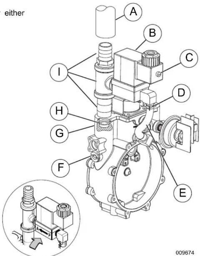
text_image
either A B C D I H G F E 009674Figure 2-3. Demand Regulator Assembly
A. Carburetor Fuel Hose
F. Jet Keeper Port
B. Solenoid Body
G. Outlet Port
C. Connector Screw
H. Fuel Jet
D. Spring Clamp
I. Black Pipe Assembly
E. Fuel Enrichment Hose
- Remove black pipe assembly from outlet port. If clearance is not sufficient, first remove fuel solenoid assembly.
- Rotate NG fuel jet counterclockwise to remove from the outlet port.
NOTE: Both the NG and LP fuel jets are slotted so that they may be removed and installed using an ordinary flat blade screwdriver.
- Rotate LP fuel jet counterclockwise to remove from the jet keeper port.
NOTE: The orifice size is stamped on each jet. The jet with the larger orifice is used for running on NG.
- Rotate LP fuel jet clockwise to install in the outlet port.
- Rotate NG fuel jet clockwise to install in the jet keeper port.
- Install fuel solenoid assembly, if removed.
NOTE: Solenoid must be installed with flow arrow pointed toward black pipe assembly. See inset of Figure 2-3.
- Apply appropriate pipe sealant to threads of black pipe assembly and install into outlet port.
NOTE: On 5.4L (48 kW) units, install two screws (with flat washers, lock washers and hex nuts) to fasten fuel inlet flange to frame rail.
- Expand spring clamp on fuel enrichment hose and install onto hose barb.
- Push power wire connector onto fuel solenoid and install screw.
- Install ca rburetor fuel hose onto outlet port.
- Install negative battery cable (black) onto negative (-) battery terminal.
- Turn on the main gas supply.
- See Change Fuel Selection.
Change Fuel Selection
NOTE: Failure to convert both the hardware and software will result in decreased performance and an increase in emissions, which is a violation of Environmental Protection Agency (EPA) regulations. It is the responsibility of the installer to make sure that only the correct recommended fuel is supplied to the generator fuel system. Thereafter, the owner/operator must ensure that only the proper fuel is supplied.
- Once fuel regulator is converted to desired fuel type call 888-9ACTIVATE for the control panel password. This fuel selection conversion is required to be password protected by EPA regulations.
- Access the control panel located behind the viewing window at the rear of the unit.
- From the Home screen, press ESCAPE to display the Main Menu.
- Navigate the software using UP ARROW, DOWN ARROW, ENTER and ESCAPE. For more detailed information, see .
Battery Requirements
| Group 26,12 Volt | 1.5L, 2.4L Engines: For areas wheretemperatures regularly drop below 32^ F( 0^ C). |
| NOTE: Battery dimensions (L x W x H) for Group 26battery must not exceed 8-3/16" x 6-13/16" x 7-3/4"(208mm x 173mm x 197mm). | |
| Group24F, 12Volt | 5.4L Engine: For areas wheretemperatures regularly drop below 32^ F( 0^ C). |
| NOTE: Battery dimensions (L x W x H) for Group 24Fbattery must not exceed 10-3/4" x 6-13/16" x 9"(273mm x 173mm x 229mm). | |
Battery Charger
A 2.5 amp battery charger is integrated into the control panel module. It operates as a "Smart Charger" which ensures output charging levels are safe and continuously optimized to promote maximum battery life.
Battery Safety Precautions
Always recycle batteries in accordance with local laws and regulations. Contact your local solid waste collection site or recycling facility to obtain information on local recycling processes. For more information on battery recycling, visit the Battery Council International website at: http://batterycouncil.org
- Stationary emergency generators installed with automatic transfer switches will crank and start automatically when NORMAL (UTILITY) source voltage is removed or is below an acceptable preset level. To prevent automatic startup and possible injury to personnel, do not connect battery cables until NORMAL source voltage at the transfer switch is correct and the system is ready to be placed into operation.
- Storage batteries give off EXPLOSIVE hydrogen gas. This gas can form an explosive mixture around the battery for several hours after charging. The slightest spark can ignite the gas and cause an explosion. An explosion can shatter the battery and cause blindness or other injury. Any area that houses a storage battery must be properly ventilated. Do not allow smoking, open flame, sparks, or any spark producing tools or equipment near the battery.
- When working on the battery, always remove watches, rings, or other metal objects, and only use tools that have insulated handles. Do not lay tools or metal parts on top of the battery.
- Discharge static electricity from the body before touching the battery by first touching a grounded metal surface.
- Wear full eye protection, protective clothing, and gloves when handling a battery.
- Immediately wash down spilled electrolyte with an acid neutralizing agent. Use a solution of 1 pound (500 grams) bicarbonate of soda to 1 gallon (4 liters) of water. Add the bicarbonate of soda solution until evidence of reaction (foaming) has ceased. Flush the resulting liquid with water.
Corrosion Protection
Periodically wash and wax the enclosure using automotive type products. Frequent washing is recommended in salt water/coastal areas.
This page intentionally left blank.
Section 3: Activation and Startup
Orientation
NOTE: The 2.4L (32 kW) unit is depicted in the artwork used in this manual. The location and appearance of some components may vary between engine models.
The side of the enclosure with the viewing window (A) is identified as the rear of the generator set. The right and left sides are identified by standing at the rear and looking towards the front of the unit. The battery is located on the side of the unit (B).

text_image
A B 009676Figure 3-1. Enclosure (Rear Left View)
Remove Side Access Panels
NOTE: Access panels are located at both the left and right sides of the enclosure.
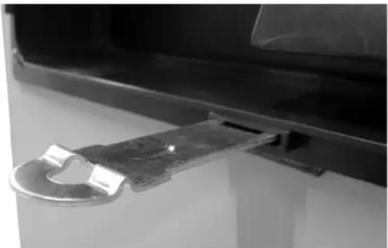
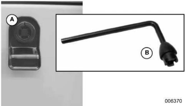
- Remove key from bag attached to door of unit.
- In sert key (B) into latch (A) and rotate counterclockwise 1/2 turn. See Figure 3-2.
- Raise pa nel using thumb latch.

natural_image
Close-up of a black plastic mechanical component with a labeled end (A) and a close-up view of its tip (B), no text or symbols present.Figure 3-2. Access Panel Key and Latch (Typical)
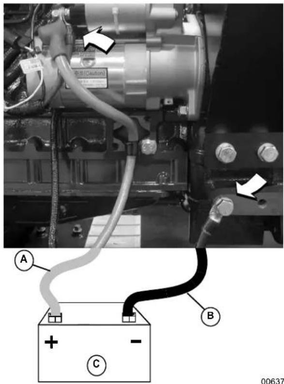
Install Battery
WARNING
Explosion. Batteries emit explosive gases. Always connect positive battery cable first to avoid spark. Failure to do so could result in death or serious injury. (000133)
- Loosen two screws with nylon washers to release hold-down clamp from battery tray.
- See Figure 3-3. Install battery (C) onto tray.
- Insta II two screws with nylon washers to secure hold-down clamp to battery tray.
- In stall positive battery cable (red) (A) to positive (+) battery terminal.
- I install negative battery cable (black) (B) to negative (-) battery terminal.
text_image
警告(Caution) A B C 00637Figure 3-3. Battery Cable Connections
Open Viewing Window
- See Figure 3-4. Remove plastic film from both sides of viewing window.
- Ro tate viewing window upward to access control panel.
- T o hold viewing window in the open position, remove rod from clip at back of window and insert into hole in frame (A).

text_image
A 006373Figure 3-4. Viewing Window
Activate Unit
Display Reads:Up Arrow = (+)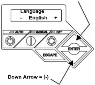 | Generator Active is displayed on the LCD screen when the unit is first powered up. After displaying firmware and hardware version codes, as well as other system information, the Installation Wizard is launched, and the Language screen is displayed.Use UP ARROW or DOWN ARROW to scroll to desired language.Press ENTER. | If the wrong language is selected, it may be changed later using the Edit menu. |
| Display Reads:Activate me (ENT) or ESC to run in manual | Press ENTER. Press ESCAPE to abort the | activation sequence. NOTACTIVATED is displayed and the generator will run in manual mode only. Disconnect and reconnect the negative battery cable to restart the activation routine. If power is removed after a successful activation, no data is lost, but the time and date must be updated. |
| Display Reads:To Activate go to www.activategen.com | Go to www.activategen.com or call 1-888-9ACTIVATE (922-8482, US & Canada only) if activation passcode is not available.If activation pass code is available, wait a few seconds for the next display. | |
| Display Reads:SN 1234567890PASS CODE XXXXX | Use UP ARROW or DOWN ARROW to increment or decrement the digit to correspond to the first number of the pass code.Press ENTER.Repeat step to enter remaining digits. | Press ESCAPE to return to preceding digits if a correction becomes necessary.If attempts to enter the activation code are unsuccessful, check the number against the code given on activategen.com. If it is correct, contact 1-888-9ACTIVATE (922-8482, US & Canada only). For international assistance, call 01-262-953-5155. |
| Display Reads:Select Hour (0-23)- 6 + | Use UP ARROW or DOWN ARROW to increment or decrement the hour. Press ENTER.Use UP ARROW or DOWN ARROW to increment or decrement the minute. Press ENTER.Use UP ARROW or DOWN ARROW to select the month. Press ENTER.Use UP ARROW or DOWN ARROW to increment or decrement the date. Press ENTER.Use UP ARROW or DOWN ARROW to increment or decrement the year. Press ENTER. | |
| Display Reads:Quiet Test Mode?Yes No | Use UP ARROW or DOWN ARROW to select either Yes or No.Press ENTER. | Select YES to perform exercise at low speed. Select NO to perform exercise at normal operating speed. |
| Display Reads:Select Hour (0-23)- 1 + | Set Exercise Time.Use UP ARROW or DOWN ARROW to increment or decrement the hour. Press ENTER.Use UP ARROW or DOWN ARROW to increment or decrement the minute. Press ENTER.Use UP ARROW or DOWN ARROW to scroll to the day of the week. Press ENTER. | In the AUTO mode, the engine starts and runs once each week at the time and day specified. During the exercise cycle, the unit runs approximately 12 minutes and then shuts down. Transfer of loads to the generator does not occur unless utility power fails. |
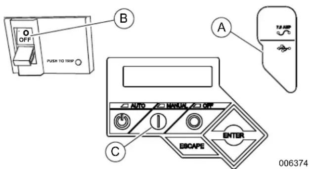
Start and Run Engine
- See Figure 3-5. Pull up rubber flap covering fuse holder and verify installation of 7.5 amp fuse (A).
- Move the Main Circuit Breaker switch down to the OFF (Open) position (B).
- Verify both auxiliary shutdown switches are ON (I). See Figure 3-6 for the locations.
- Pr ess MANUAL on the control panel (C) to start the engine. A blue LED illuminates to confirm that the system is in the MANUAL mode.
- Allo w the engine to run until it reaches normal operating temperature.
- Pr ess OFF on the control panel to stop the engine. A red LED illuminates to confirm that the system is in the OFF mode.
text_image
OFF PUSH TO TRIP A B C AUTO MANUAL OFF EBAPE ENTER TJ-APR 006374Figure 3-5. Generator Control Panel
Operational Checks
NOTE: The following procedures require special tools and skills. Contact an IASD to perform these tasks.
Self Test
Upon power up, the controller goes through a system self test which checks for the presence of utility voltage on the DC circuits. This is done to prevent damage if the installer mistakenly connects AC utility power sense wires into the DC terminal block. If utility voltage is detected, the controller displays a warning message and locks out the generator, thereby preventing damage to the controller. Remove power to the controller to clear this warning.
Utility voltage must be turned on and present at the N1 and N2 terminals inside the generator control panel for this test to be performed and pass.
Before starting, complete the following:
- V erify the generator is OFF. A red LED on the control panel illuminates to confirm that the system is in the OFF mode.
- Verify the Main Circuit Breaker switch on the generator control panel is in the OFF (Open) position.
- T urn off all circuit breakers/electrical loads that will be powered by the generator.
- Verify both auxiliary shutdown switches are ON (I). See Figure 3-6 for the locations.
- Check the coolant and engine lubricating oil levels. See Check Coolant Level and Hoses and Check Lubricating Oil Level and Drain Hose.
During initial start up only, the generator may exceed the normal number of start attempts and experience an “over crank” fault. This is due to accumulated air in the fuel system during installation. Reset the control board and restart up to two more times, if necessary. If unit fails to start, contact an IASD for assistance.
Check Manual Transfer Switch Operation
Refer to the manufacturer's instructions.

DANGER
Electrocution. Do not manually transfer under load. Disconnect transfer switch from all power sources prior to manual transfer. Failure to do so will result in death or serious injury, and equipment damage. (000132)
Electrical Checks
Complete electrical checks as follows:
- V erify that the generator is OFF. A red LED on the control panel illuminates to confirm that the system is in the OFF mode.
- Verify that the Main Circuit Breaker switch on generator control panel is in the OFF (Open) position.
- T urn OFF all circuit breakers/electrical loads that will be powered by the generator.
- T urn on the utility power supply to the transfer switch using the means provided (such as a utility main line circuit breaker).

DANGER
Electrocution. High voltage is present at transfer switch and terminals. Contact with live terminals will result in death or serious injury. (000)
- Use an accurate AC voltmeter to check utility power source voltage across transfer switch terminals N1, N2, and N3 (if three phase). Normal line-to-line voltage should be equivalent to rated unit voltage.
- Check utility power source voltage across terminals N1, N2, and N3 (if three phase) and the transfer switch neutral lug.
- When certain that utility supply voltage is compatible with transfer switch and load circuit ratings, turn OFF the utility power supply to the transfer switch.
- Pr ess MANUAL on the control panel to crank and start the engine.
- Allow the engine to warm up for about five minutes. Move the Main Circuit Breaker switch on the
generator control panel up to the ON (or closed) position.
- Connect an accurate AC frequency meter across transfer switch terminal lugs E1, E2, and E3 (if three phase) and verify the proper rated frequency (50 Hz or 60 Hz).
- Use an accurate AC voltmeter to check generator output voltage across transfer switch terminals E1 to E2, (E2 to E3 and E3 to E1 if three phase). Normal line-to-line voltage should be equivalent to site specific utility voltage.
- Successively connect the AC voltmeter test leads across terminal lugs E1 and Neutral, then E2 and Neutral (and E3 and Neutral if three phase). Line-to-neutral reading in each case should match utility voltage reading. If system is three phase, verify that generator phase rotation matches utility phase rotation.
- Move the Main Circuit Breaker switch on the generator control panel down to the OFF (Open) position.
- Press OFF on the control panel to shut the engine down.
NOTE: Do not proceed unless certain that generator AC voltage and frequency are correct and within the stated limits.
Test Generator Under Load
To test the generator set with electrical loads applied, proceed as follows:
- Verify that the generator is OFF. A red LED on the control panel illuminates to confirm that the system is in the OFF mode.
- T urn OFF all breakers/electrical loads that will be powered by the generator.
- T urn OFF the utility power supply to the transfer switch, using the means provided (such as a utility main line circuit breaker).

DANGER
Electrocution. Do not manually transfer under load. Disconnect transfer switch from all power sources prior to manual transfer. Failure to do so will result in death or serious injury, and equipment damage. (000132)
- Manually set the transfer switch to the STANDBY position, i.e., load terminals connected to the generator's E1, E2, and E3 (if three phase) terminals.
- Pr ess MANUAL on the control panel. The engine will crank and start.
- Allow the engine to warm up for a few minutes.
- Mo ve the Main Circuit Breaker switch on the generator control panel up to the ON (or closed)
position. The switch is now powered by the standby generator.
- T urn ON the circuit breaker/electrical loads powered by the generator.
- Con nect a calibrated AC voltmeter and a frequency meter across terminal lugs E1, E2, and E3 (if three phase). Voltage should be approximately unit rated voltage. Check with clamp on amp meter to ensure unit is not overloaded.
- Let the generator run at full rated load for 20-30 minutes. Listen for unusual noises, vibration, or other indications of abnormal operation. Check for oil leaks, evidence of overheating, etc.
- When testing under load is complete, turn OFF electrical loads.
- Move the Main Circuit Breaker switch on the generator control panel up to the OFF (or open) position.
- Allow the engine to run at no-load for 2-5 minutes.
- Press OFF on the control panel to shut the engine down. A red LED illuminates to confirm that the system is in the OFF mode.
Test Auxiliary Shutdown Switch Operation
The generator is equipped with an independent means of shutting down prime mover (engine) for use in emergency situations. The shutdown mechanism, when activated, requires a mechanical reset.
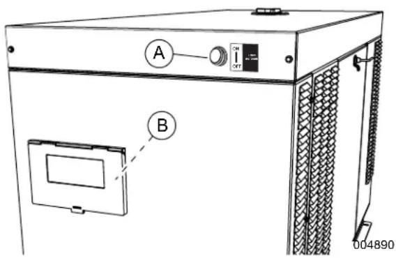
See Figure 3-6. Generators 15 kW and larger are equipped with two auxiliary shutdown switches. One auxiliary shutdown switch (A) is located on the generator roof above and to the right of the viewing window. The second auxiliary shutdown switch (B) is inside the control panel enclosure.
text_image
A B 004890Figure 3-6. Auxiliary Shutdown Switches
Test auxiliary shutdown switches after installation to verify correct operation.
- V erify auxiliary shutdown switches are ON (I).
-
Pre ss MANUAL key on control panel keypad to start engine.
-
With engine running, set one auxiliary shutdown switch to OFF (O). Engine should shut down immediately.
-
If engine stops, set auxiliary shutdown switch to ON (I), clear alarm on controller, and restart engine to verify generator is operating normally. After verifying normal operation of first auxiliary switch, verify operation of second auxiliary switch.
- If engine does not stop, auxiliary shutdown switch is not functioning correctly. Contact an IASD.
NOTE: Auxiliary shutdown switches are not intended to be a primary means to shut down generator under normal operating conditions. Accidental activation of an auxiliary shutdown switch will prevent generator from operating during a power outage.
Check Automatic Operation
To check the system for proper automatic operation, proceed as follows:
- V erify that the generator is OFF. A red LED on the control panel illuminates to confirm that the system is in the OFF mode.
- Inst all front cover of the transfer switch.
- T urn ON the utility power supply to the transfer switch, using the means provided (such as a utility main line circuit breaker).
NOTE: Transfer Switch will transfer back to utility position.
- Mo ve the Main Circuit Breaker switch on the generator control panel up to the ON (or closed) position.
- Pre ss AUTO on the control panel. The system is now ready for automatic operation.
- T urn OFF the utility power supply to the transfer switch.
With the generator ready for automatic operation, the engine will crank and start when the utility source power is turned OFF after a 10 second delay (factory default setting). After starting, the transfer switch connects load circuits to the standby side. Let the system operate through its entire automatic sequence of operation.
With the generator running and loads powered by generator AC output, turn ON the utility power supply to the transfer switch. The system transfers back to the utility position and then runs through the cool down cycle and shuts down.
Securing the Generator
- Use key to install left and right side access panels.
- Close viewing window .
NOTE: Obtain viewing window hasp, if not installed. See Figure 3-7 With the retaining tab at the bottom, insert square end of hasp into slot below viewing window. Push on hasp until it snaps in place. Gently pull on hasp to verify that it will not come free.
- Install cu stomer supplied padlock into hasp.
natural_image
Close-up of a metal hinge attached to a black vehicle door (no visible text or symbols)006376
Figure 3-7. Install Viewing Window Hasp
This page intentionally left blank.
Section 4: Operation
Control Panel
NOTE: The control panel is intended for use by qualified service personnel only.
The control panel is located behind the viewing window at the rear of the unit. See Figure 3-5 and Figure 4-1.
! DANGER
Automatic start-up. Disconnect utility power and render unit inoperable before working on unit. Failure to do so will result in death or serious injury.
(000191)
NOTE: For added security, place a DO NOT OPERATE tag or placard on both the control panel and transfer switch.
Auto/Manual/Off
| Feature Description | |
| AUTO | Press to activate fully automatic operation. Green LED illuminates to confirm that system is in AUTO mode.Transfer to standby power occurs if utility power fails.Functionality of exercise timer is enabled, if set. |
| MANUAL | Press to crank and start engine. Blue LED illuminates to confirm that system is in MANUAL mode.Transfer to standby power occurs if utility power fails.Functionality of exercise timer is disabled. |
| OFF | Press to shut down engine, if running. Red LED illuminates to confirm that system is in OFF mode.Transfer to standby power does not occur if utility power fails. |
text_image
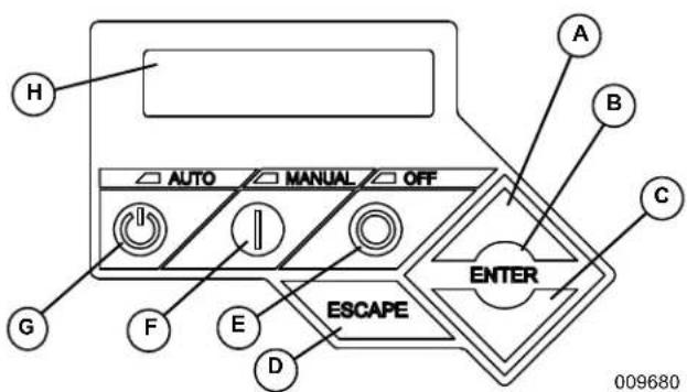
AUTO MANUAL OFF A B C ENTER ESCAPE D E F G H 009680Figure 4-1. Control Panel and LCD Screen
| A. Up Arrow |
| B. Enter |
| C. Down Arrow |
| D. Escape |
| E. Off |
| F.Manual |
| G. Auto |
| H. LCD Screen |
Menu Navigation
See Figure 4-2.
| Feature Description | |
| System Menus | |
| HOME Screen | The system returns to the Home screen if the control panel is not used for five minutes. The screen normally displays a Status message, such as Ready to Run (Auto mode) or Switched to OFF (Off mode), and the total Hours of Protection. If an active alarm/warning condition occurs, the associated Alarm/Warning message is displayed. To clear the Alarm/Warning message, press OFF on the control panel followed by ENTER. In the event of multiple Alarms/Warnings, the next message is then displayed. The highest priority alarm is always displayed first. |
| Display Backlight | Normally off. If the operator presses any button, the backlight will automatically light and remain on for 30 seconds. |
| MAIN MENU | Enables the operator to navigate the software using UP ARROW, DOWN ARROW, ENTER and ESCAPE. The Main Menu can be accessed from any sub menu by consecutively pressing ESCAPE. Each time ESCAPE is pressed, the preceding menu is displayed. The Main Menu is reached when the System, Date/Time, Battery, and Sub Menus are displayed. |
| SUB-MENUS | The Sub-Menus screen includes HISTORY, MAINT, EDIT, AND DEALER menus. |
| HISTORY | The HISTORY screen includes an Alarm Log and Run Log. The Alarm Log displays the last 50 alarm events. The Run Log displays the last 50 operational events. |
| MAINTENANCE MENU | Includes Run Hours, Maintenance Log, and Schedule. Run Hours displays cumulative hours on engine. Maintenance Log displays the last service warnings and service completions. Scheduled displays when the next scheduled maintenance interval warning will occur. |
| EDIT MENU | Includes Language, Current Date/Time, Exercise Settings, Firmware Update, Startup Delay, and Warm up Time. All of these settings are adjustable without a password. |
| DEALER MENU | Includes settings that are password protected and can be adjusted by an Independent Authorized Service Dealer during installation or a service visit. |
| Navigation | |
| ESCAPE Used | to abort a routine or back u p to the preceding menu. |
| ENTER Used | to make a selection or save an entry. |
| UP ARROW DOWN ARROW | Used to move forward or backward from menu to menu or to scroll forward or backward (increment or decrement) through available selections. |
| NOTE: Pressing the control panel illuminates the backlight for 30 seconds. The backlight also illuminates for 30 seconds whenever an active Alarm/Warning message is displayed. | |

flowchart
graph TD
A["Home Screen"] --> B["Switched to 'OFF' Hours of Protection 0 (H)"]
B --> C["SYSTEM"]
C --> D["DATE/TIME"]
D --> E["BATTERY"]
E --> F["SUB MENUS"]
F --> G["Main Menu"]
G --> H["Run Hours (H) 0.0"]
H --> I["Run Hrs"]
I --> J["Scheduled"]
J --> K["EXAMPLE: 'Inspect Battery 200 RnHr or 12/27/14'<br>Service Schedule A, B or C'<br>Next Maintenance 200 RnHr or 12/27/14'"]
K --> L["Current Date/Time 02/14/14 04:00"]
L --> M["Current Date/Time 02/14/14 04:00"]
M --> N["Current Date/Time 02/14/14 04:00"]
N --> O["Current Date/Time 02/14/14 04:00"]
O --> P["Current Date/Time 02/14/14 04:00"]
P --> Q["Current Date/Time 02/14/14 04:00"]
Q --> R["Current Date/Time 02/14/14 04:00"]
R --> S["Current Date/Time 02/14/14 04:00"]
S --> T["Current Date/Time 02/14/14 04:00"]
T --> U["Current Date/Time 02/14/14 04:00"]
U --> V["Current Date/Time 02/14/14 04:00"]
V --> W["Current Date/Time 02/14/14 04:00"]
W --> X["Current Date/Time 02/14/14 04:00"]
X --> Y["Current Date/Time 02/14/14 04:00"]
Y --> Z["Current Date/Time 02/14/14 04:00"]
Z --> AA["Current Date/Time 02/14/14 04:00"]
AA --> AB["Current Date/Time 02/14/14 04:00"]
AB --> AC["Current Date/Time 02/14/14 04:00"]
AC --> AD["Current Date/Time 02/14/14 04:00"]
AD --> AE["Current Date/Time 02/14/14 04:00"]
AE --> AF["Current Date/Time 02/14/14 04:00"]
AF --> AG["Current Date/Time 02/14/14 04:00"]
AG --> AH["Current Date/Time 02/14/14 04:00"]
AH --> AI["Current Date/Time 02/14/14 04:00"]
AI --> AJ["Current Date/Time 02/14/14 04:00"]
AJ --> AK["Current Date/Time 02/14/14 04:00"]
AK --> AL["Current Date/Time 02/14/14 04:00"]
AL --> AM["Current Date/Time 02/14/14 04:00"]
AM --> AN["Current Date/Time 02/14/14 04:00"]
AN --> AO["Current Date/Time 02/14/14 04:00"]
AO --> AP["Current Date/Time 02/14/14 04:00"]
AP --> AQ["Current Date/Time 02/14/14 04:00"]
AQ --> AR["Current Date/Time 02/14/14 04:00"]
AR --> AS["Current Date/Time 02/14/14 04:00"]
AS --> AT["Current Date/Time 02/14/14 04:00"]
AT --> AU["Current Date/Time 02/14/14 04:00"]
AU --> AV["Current Date/Time 02/14/14 04:00"]
AV --> AW["Current Date/Time 02/14/14 04:00"]
AW --> AX["Current Date/Time 02/14/14 04:00"]
AX --> AY["Current Date/Time 02/14/14 04:00"]
AY --> AZ["Current Date/Time 02/14/14 04:00"]
AZ --> BA["Current Date/Time 02/14/14 04:00"]
BA --> BB["Current Date/Time 02/14/14 04:00"]
AE --> BC["Warning Message(S)<br>"Low Battery"<br>"Exercise Set Error"<br>"Schedule A Maint"<br>"Schedule B Maint"<br>"Schedule C Maint"<br>"Battery Problem"<br>"Charger Warning"<br>"Charger Missing AC"<br>"USB Warning"<br>"Download Failure"<br>"Check Engine""]
AE --> BD["ALARM MESSAGE(S)<br>"High Engine Temp"<br>"Low Oil Pressure"<br>"Overcrank"<br>"Overspout"<br>"RPM Sense Loss"<br>"Underspout"<br>"Controller Fault"<br>"Ignition Fault Code"<br>"WIRING ERROR"<br>"Over Voltage"<br>"Under Voltage"<br>"Overload"<br>"Canbus Error"<br>"Missing Cam Pulse"<br>"Missing Cran Pulse"<br>"Low Fuel Pressure"<br>"E-Stop""]
AE --> BE["ALARM MESSAGE(S)<br>"High Engine Temp"<br>"Low Oil Pressure"<br>"Overcrank"<br>"Overspout"<br>"RPM Sense Loss"<br>"Underspout"<br>"Controller Fault"<br>"Ignition Fault Code"<br>"WIRING ERROR"<br>"Over Voltage"<br>"Under Voltage"<br>"Overload"<br>"Canbus Error"<br>"Missing Cam Pulse"<br>"Missing Cran Pulse"<br>"E-Stop""]
AE --> BF["ALARM MESSAGE(S)<br>"High Engine Temp"<br>"Low Oil Pressure"<br>"Overcrank"<br>"Overspout"<br>"RPM Sense Loss"<br>"Underspout"<br>"Controller Fault"<br>"Ignition Fault Code"<br>"WIRING ERROR"<br>"Over Voltage"<br>"Under Voltage"<br>"Overload"<br>"Canbus Error"<br>"Missing Cam Pulse"<br>"E-Stop""]
AE --> BG["ALARM MESSAGE(S)<br>"High Engine Temp"<br>"Low Oil Pressure"<br>"Overcrank"<br>"Overspout"<br>"RPM Sense Loss"<br>"Underspout"<br>"Controller Fault"<br>"Ignition Fault Code"<br>"WIRING ERROR"<br>"Over Voltage"<br>"Under Voltage"<br>"Overload"<br>"E-Stop""]
AE --> BH["ALARM MESSAGE(S)<br>"High Engine Temp",<br>"Low Oil Pressure",<br>"Overcrank",<br>"Overspout",<br>"RPM Sense Loss",<br>"Underspout",<br>"Controller Fault",<br>"Ignition Fault Code",<br>"WIRING ERROR",<br>"Over Voltage",<br>"E-Stop""]
AE --> BI["ALARM MESSAGE(S)<br>"High Engine Temp",<br>"Low Oil Pressure",<br>"Overcrank",<br>"Overspout",<br>"RPM Sense Loss",<br>"Underspout",<br>"Controller Fault",<br>"Ignition Fault Code",<br>"WIRING ERROR",<br>"E-Stop""]
AE --> BJ["ALARM MESSAGE(S)<br>"High Engine Temp",<br>"Low Oil Pressure",<br>"Overcrank",<br>"Overspout",<br>"RPM Sense Loss",<br>"Underspout",<br>"E-Stop""]
AE --> BK["ALARM MESSAGE(S)<br>"High Engine Temp",<br>"Low Oil Pressure",<br>"Overcrank",<br>"Overspout",<br>"RPM Sense Loss",<br>"Underspout",<br>"E-Stop""]
AE --> BL["ALARM MESSAGE(S)<br>"High Engine Temp",<br>"Low Oil Pressure",<br>"Overcrank",<br>"Overspout",<br>"RPM Sense Loss",<br>"Underspout",<br>"E-Stop""]
AE --> BM["ALARM MESSAGE(S)<br>"High Engine Temp",<br>"Low Oil Pressure",<br>"Overcrank",<br>"Overspout",<br>"RPM Sense Loss",<br>"Underspout",<br>"E-Stop""]
AE --> BN["ALARM MESSAGE(S)<br>"High Engine Temp",<br>"Low Oil Pressure",<br>"Overcrank",<br>"Overspout",<br>"RPM Sense Loss",<br>"Underspout",<br>"E-Stop""]
AE --> BO["ALARM MESSAGE(S)<br>"High Engine Temp",<br>"Low Oil Pressure",<br>"Overcrank",<br>"Overspout",<br>"RPM Sense Loss",<br>"Underspout",<br>"E-Stop""]
AE --> BP["ALARM MESSAGE(S)<br>"High Engine Temp",<br>"Low Oil Pressure",<br>"Overcrank",<br>"Overspout",<br>"RPM Sense Loss",<br>"Underspout",<br>"E-Stop""]
AE --> BQ["ALARM MESSAGE(S)<br>"High Engine Temp",<br>"Low Oil Pressure",<br>"Overcrank",<br>"Overspout",<br>"RPM Sense Loss",<br>"Underspout",<br>"E-Stop""]
AE --> BR["ALARM MESSAGE(S)<br>"High Engine Temp",<br>"Low Oil Pressure",<br>"Overcrank",<br>"Overspout",<br>"RPM Sense Loss",<br>"Underspout",<br>"E-Stop""]
AE --> BS["ALARM MESSAGE(S)<br>"High Engine Temp",<br>"Low Oil Pressure",<br>"Overcrank",<br>"Overspout",<br>"RPM Sense Loss",<br>"Underspout",<br>"E-Stop""]
AE --> BT["ALARM MESSAGE(S)<br>"High Engine Temp",<br>"Low Oil Pressure",<br>"Overcrank",<br>"Overspout",<br>"RPM Sense Loss",<br>"Underspout",<br>"E-Stop""]
AE --> BU["ALARM MESSAGE(S)<br>"High Engine Temp,<br>"Low Oil Pressure",<br> "Overcrank",<br> "Overspout",<br> "RPM Sense Loss",<br> "Underspout",<br> "Controller Fault", "Wiring Error", "Over Voltage", "Under Voltage", "Overload", "Canbus Error", "Missing Cam Pulse", "Missing Cran Pulse", "E-Stop""]
AE --> BV["ALARM MESSAGE(S)<br>'High Engine Temp',<br>'Low Oil Pressure',<br>'Overcrank',<br>'Overspout',<br>'RPM Sense Loss',<br>'Underspout',<br>'Controller Fault', "Ignition Fault Code',<br>'Over Voltage', "Under Voltage", "Overload", "Canbus Error", "Missing Cam Pulse", "Missing Cran Pulse", "E-Stop""]
AE --> BW["ALARM MESSAGE(S)<br>'High Engine Temp',<br>'Low Oil Pressure',<br>'Overcrank',<br>'Overspout',<br>'RPM Sense Loss',<br>'Underspout',<br>'Controller Fault', "Ignition Fault Code',<br>'Over Voltage', "Under Voltage", "Overload", "Canbus Error", "Missing Cam Pulse", "Missing Cran Pulse", "E-Stop""]
AE --> BX["ALARM MESSAGE(S)<br>'High Engine Temp',<br>'Low Oil Pressure',<br>'Overcrank',<br>'Overspout',<br>'RPM Sense Loss',<br>'Underspout',<br>'Controller Fault', "Ignition Fault Code',<br>'Over Voltage', "Under Voltage", "Overload", "Canbus Error", "Missing Cam Pulse", "Missing Cran Pulse", "E-Stop""]
AE --> BY["ALARM MESSAGE(S)<br>'High Engine Temp',<br>'Low Oil Pressure',<br>'Overcrank',<br>'Overspout',<br>'RPM Sense Loss',<br>'Underspout',<br>'Controller Fault', "Ignition Fault Code',<br>'Over Voltage', "Under Voltage", "Overload", "Canbus Error", "Missing Cam Pulse", "Missing Cran Pulse", "E-Stop""]
AE --> BZ["ALARM MESSAGE(S)<br>'High Engine Temp',<br>'Low Oil Pressure',<br>'Overcrank',<br>'Overspout',<br>'RPM Sense Loss',<br>'Underspout',<br>'Controller Fault', "Ignition Fault Code',<br>'Over Voltage', "Under Voltage", "Overload", "Canbus Error", "Missing Cam Pulse", "Missing Cran Pulse", "E-Stop""]
AE --> CA["ALARM MESSAGE(S)<br>'High Engine Temp',<br>'Low Oil Pressure',<br>'Overcrank',<br>'Overspout',<br>'RPM Sense Loss',<br>'Underspout',<br>'Controller Fault', "Ignition Fault Code',<br>'Over Voltage', "Under Voltage", "Overload", "Canbus Error", "Missing Cam Pulse", "Missing Cran Pulse", "E-Stop""]
AE --> CB["ALARM MESSAGE(S)<br>'High Engine Temp',<br>'Low Oil Pressure',<br>'Overcrank',<br>'Overspout',<br>'RPM Sense Loss',<br>'Underspout',<br>'Controller Fault', "Ignition Fault Code',<br>'Over Voltage', "Under Voltage", "Overload", "Canbus Error", "Missing Cam Pulse", "Missing Cran Pulse", "E-Stop""]
AE --> CC["ALARM MESSAGE(S)<br>'High Engine Temp,<br>'Low Oil Pressure',<br>'Overcrank',<br>'Overspout',<br>'RPM Sense Loss',<br>'Underspout',<br>'Controller Fault', "Ignition Fault Code',<br>'Over Voltage', "Under Voltage", "Overload", "Canbus Error", "Missing Cam Pulse", "Missing Cran Pulse", "E-Stop""]
AE --> DD["ALARM MESSAGE(S)<br>'High Engine Temp,<br>'Low Oil Pressure',<br>'Overcrank',<br>'Overspout',<br>'RPM Sense Loss',<br>'Underspout',<br>'Controller Fault', "Ignition Fault Code',<br>'Over Voltage', "Under Voltage", "Overload", "Canbus Error", "Missing Cam Pulse", "Missing Cran Pulse", "E-Stop""]
AE --> DE["ALARM MESSAGE(S)<br>'High Engine Temp,<br>'Low Oil Pressure',<br>'Overcrank',<br>'Overspout',<br>'RPM Sense Loss',<br>'Underspout',<br>'Controller Fault', "Ignition Fault Code',<br>'Over Voltage', "Under Voltage", "Overload", "Canbus Error", "Missing Cam Pulse", "Missing Cran Pulse", "E-Stop""]
AE --> DF["ALARM MESSAGE(S)<br>'High Engine Temp,<br>'Low Oil Pressure',<br>'Overcrank',<br>'Overspout',<br>'RPM Sense Loss',<br>'Underspout',<br>'Controller Fault', "Ignition Fault Code',<br>'Over Voltage', "Under Voltage", "Overload", "Canbus Error", "Missing Cam Pulse", "Missing Cran Pulse", "E-Stop""]
AE --> DG["ALARM MESSAGE(S)<br>'High Engine Temp,<br>'Low Oil Pressure',<br>'Overcrank',<br>'Overspout',<br>'RPM Sense Loss',<br>'Underspout',<br>'Controller Fault', "Ignition Fault Code',<br>'Over Voltage', "Under Voltage", "Overload", "Canbus Error", "Missing Cam Pulse", "Missing Cran Pulse", "E-Stop""]
AE --> DH["ALARM MESSAGE(S)<br>'High Engine Temp,<br>'Low Oil Pressure',<br>'Overcrank',<br>'Overspout',<br>'RPM Sense Loss',<br>'Underspout',<br>'Controller Fault', "Ignition Fault Code',<br>'Over Voltage', "Under Voltage", "Overload", "Canbus Error", "Missing Cam Pulse", "Missing Cran Pulse", "E-Stop""]
AE --> DI["ALARM MESSAGE(S)<br>'High Engine Temp,<br>'Low Oil Pressure',<br>'Overcrank',<br>'Overspout',<br>'RPM Sense Loss',<br>'Underspout',<br>'Controller Fault', "Ignition Fault Code',<br>'Over Voltage', "Under Voltage", "Overload", "Canbus Error", "Missing Cam Pulse", "Missing Cran Pulse", "E-Stop""]
AE --> DJ["ALARM MESSAGE(S)<br>'High Engine Temp,<br>'Low Oil Pressure',<br>'Overcrank',<br>'Overspout',<br>'RPM Sense Loss',<br>'Underspout',<br>'Controller Fault', "Ignition Fault Code<br>, 'Under Voltage', 'Under Voltage', 'Possible Message(s) Corrupted File Invalid File File Not Found<br>Unsupported Device Controller Fault', 'GUI V XXX To XXX*''"] ]
AE --> DK["ALARM MESSAGE(S)<br>'High Engine Temp,<br>'Low Oil Pressure',<br>'Overcrank',<br>'Overspout',<br>'RPM Sense Loss<br>, 'Underspout<br>, 'Controller Fault'<br>, 'Ignition Fault Code<br>, 'Under Voltage<br>, 'Under Voltage'<br>, 'Canbus Error<br>, 'Missing Cam Pulse'<br>, 'Missing Cran Pulse'<br>, 'E-Stop'<br>"] ]
Figure 4-2. Navigation Menu
Alarm/Warning Conditions
The owner/operator is alerted to Alarm and/or Warning conditions via the control panel LCD screen. All Alarm conditions cause the generator to shut down.
The Warning messages alert the operator to conditions that do not disable the unit or require immediate correction.
The possible Alarm/Warning messages are listed below.
| Alarm Messages Warning Messages | |||
| •High Engine Temperature•Low Oil Pressure•Overcrank•Overspeed•RPM Sense Loss•Underspeed•Controller Fault•Ignition Fault Code•Auxiliary Shutdown | •WIRING ERROR•Over Voltage•Under Voltage•Overload•Canbus Error•Missing Cam Pulse•Missing Crank Pulse•Low Fuel Pressure•E-Stop | •Low Battery•Exercise Set Error•Schedule A Maintenance•Schedule B Maintenance•Schedule C Maintenance•Battery Problem | •Charger Warning•Charger Missing AC•USB Warning•Download Failure•Check Engine |
NOTE: Unless properly trained to correct and clear Alarm/Warning conditions, contact an IASD.
Change Time and Date
To change the time and date after activation, see the Navigation Menu in Figure 4-3. If power is lost (battery is disconnected/reconnected, control panel fuse is removed/installed, etc.), the display automatically prompts the user for the Time and Date. All other information is retained in memory.
Programmable Timers
Dealer Programmable
Exercise Time
A programmable exercise time is provided. In the AUTO mode, the engine starts and runs once each week at the time and day specified. During the exercise cycle, the unit runs approximately 12 minutes and then shuts down. Transfer of loads to the generator does not occur unless utility power fails.
NOTE: A Dealer password is required to change the duration of Exercise Cycle.
User Programmable
Start-Up Delay Timer
A programmable line interrupt delay (or Start-Up Delay) timer is provided. When utility voltage fails (falls below 60% of nominal), the start-up delay timer is started. If the voltage rises above the Utility Volts Low threshold, the timer is reset. If the utility voltage remains below the threshold during the duration of the timer, the unit cranks and starts.
NOTE: The factory default setting is five seconds, but is adjustable from 2 to 1500 seconds.
Warm-Up Delay Timer
A programmable Warm-Up Delay timer is provided. As soon as the generator starts, the warm-up timer is started. When the warm-up timer expires, the control transfers load to the generator (through the transfer switch) if the utility voltage is less than 80% of nominal. If utility voltage is greater than the threshold at expiration of the warm-up time, the load is not transferred to the generator and a cool-down period begins. At the end of the cool-down period, the generator stops.
NOTE: The factory default setting is five seconds, but is adjustable from 5 to 1500 seconds.
USB Port for Firmware Updates
A USB port is located beneath the rubber flap on the control panel and is provided for firmware updates. Firmware updates must be performed by an Independent Authorized Service Dealer.
NOTE: The USB port is intended for use with a USB thumb drive only. The USB port is not intended for charging devices such as phones or laptops. Do not connect any consumer electronics to the USB port. Contact an IASD for any firmware updates.
Battery Charger
NOTE: The battery charger is integrated into the control panel module.
The battery charger ensures:
- Output is continually optimized to promote maximum battery life.
- Charging levels are safe.
NOTE: A warning message is displayed on the LCD screen when the battery requires service.
Transfer Switch Automatic Operation
In AUTO, the generator starts automatically when utility source voltage drops below the preset level. Once the unit starts, loads are transferred to the standby power source.
To select automatic operation:
- Verify that the transfer switch main contacts are set to the UTILITY position (loads connected to the utility power source).
- Verify that normal UTILITY power source voltage is available to transfer switch terminal lugs N1, N2 and N3 (if three phase).
- Move the Main Circuit Breaker switch on the control panel up to the ON (Closed) position.
- Press AUTO on the control panel. A green LED illuminates to confirm that the system is in the AUTO mode.
Automatic Sequence of Operation
Utility Failure
If the control panel is set to AUTO when the utility power fails, a ten second Start-Up Delay timer is started (user programmable). If utility power is still absent when the time expires, the engine cranks and starts.
Once started, a five second engine Warm-Up Delay timer starts (user programmable). When the time has elapsed, the load is transferred to the generator. If utility power is restored (above 90% of nominal, dealer programmable) between the time the engine is first started and expiration of the warm-up time, the controller completes the start cycle and then runs through its normal cool-down cycle (while the load remains on the utility source throughout the episode).
Cranking
The cyclic cranking is controlled as follows:
Fifteen (15) seconds crank, seven (7) seconds rest, seven (7) seconds crank, seven (7) seconds rest; this sequence is repeated for a total of six (6) crank cycles.
Load Transfer
With the generator running, the transfer of load is dependent upon the operating mode as follows:
| AUTO | Starts and runs if utility power fails (falls below 60% of nominal) forfiveconsecutive seconds (adjustable).Starts afivesecond (adjustable) engine warm-up timer.Does not execute transfer if utility power returns before expiration of warm-up timer (but finishes the warm-up and cool-down cycles).Transfers back to utility once utility power returns (above 80% of nominal) forfifteenconsecutive seconds.Only shuts down if OFF is pressed or an alarm shutdown occurs.Once utility power returns, starts a cool-down cycle before it shuts down.NOTE:Cool-down cycle isfiveminutes if turbocharger equipped, one minute if naturally aspirated. |
| EXERCISE | |
| Only works in AUTO mode.Does not exercise if generator is already running in AUTO.During exercise cycle, transfers only if utility power fails fortenconsecutive seconds. | |
| MANUAL | Engine cranks and runs even if utility power is present, but does not transfer to generator.Transfers to generator if utility fails (falls below 60% of nominal) fortenconsecutive seconds.Transfers back to utility when utility returns forfifteenconsecutive seconds. The engine continues to run until the AUTO or OFF key is pressed. |
Transfer Switch Manual Operation

DANGER
Electrocution. Do not manually transfer under load. Disconnect transfer switch from all power sources prior to manual transfer. Failure to do so will result in death or serious injury, and equipment damage. (000132)
Prior to automatic operation, manually exercise the transfer switch to verify that the interference with proper operation of the mechanism. Manual operation of the transfer switch is required if automatic operation fails.
IMPORTANT NOTE: Always use the applicable transfer switch owner's manual for actual manual transfer switch operation instructions. The information presented here describes a transfer switch, which is not used for three phase applications. See specific manual for three phase transfer switch.
Transfer to Generator Power
When utility power fails, manually transfer to standby power and start the generator as follows:
- Press OFF on the control panel. A red LED illuminates to confirm that the system is in the OFF mode.
- Move the Main Circuit Breaker switch down to the OFF (Open) position.
- Turn off the utility power supply to the transfer switch using the means provided (such as a utility main line circuit breaker).
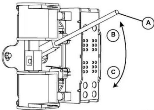
e4. i Use the manual transfer handle (A) inside the transfer switch to move the main contacts to the STANDBY position (loads connected to the standby power source) (C).
- Press MANUAL on the control panel. The engine cranks and starts.
- Allow the engine to run for two minutes to bring it up to normal operating temperature.
- Move the Main Circuit Breaker switch up to the ON (Closed) position.
text_image
Technical diagram of a mechanical device with labeled components A, B, and C, showing directional arrows indicating movement or flow.006375
Figure 4-3. Manual Transfer Switch Operation (Typical)
NOTE: V-style transfer switch not used for three phase applications.
Transfer Back to Utility Power
When utility power is restored, manually transfer back to utility power and shut down the generator as follows:
NOTE: Verify that utility voltage has returned and is at the proper value.
-
M ove the Main Circuit Breaker switch down to the OFF (Open) position.
-
Allow the engine to run for two minutes at no-load to bring it up to normal operating temperature.
-
Pre ss OFF on the control panel to shut down the engine.
-
Verify that utility power supply to the transfer switch is turned off.
-
Use the manual transfer handle inside the transfer switch to move the main contacts to the UTILITY position (loads connected to the utility power source) (B).
-
T urn on the utility power supply to the transfer switch using the means provided.
-
Pre ss AUTO on the control panel. A green LED illuminates to confirm that the system is in the AUTO mode.
This page intentionally left blank.
Section 5: Maintenance
Component Locations
The side of the enclosure with the viewing window is identified as the rear of the generator set. The right and left sides are identified by standing at the rear and looking towards the front of the unit.
NOTE: The 2.4L (32 kW) unit is depicted in the artwork used in this manual. The location and appearance of some components may vary between engine models.

text_image
A B C D E F 006378| A 7.5 Amp Fuse and USB Port |
| B Control Panel and LCD Screen |
| C Main Circuit Breaker |
| D Viewing Window |
| E Left Side |
| F Right Side |
Figure 5-1. Rear View
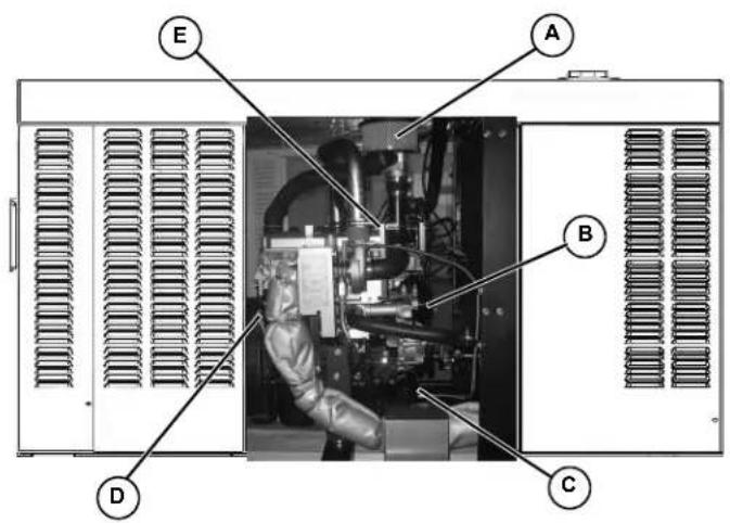
text_image
A B C D E| A Air Filter Element |
| B Timing Belt |
| C Oil Filter |
| D Oil Level Dipstick |
| E Oil Fill Cap |
Figure 5-2. Right Side View
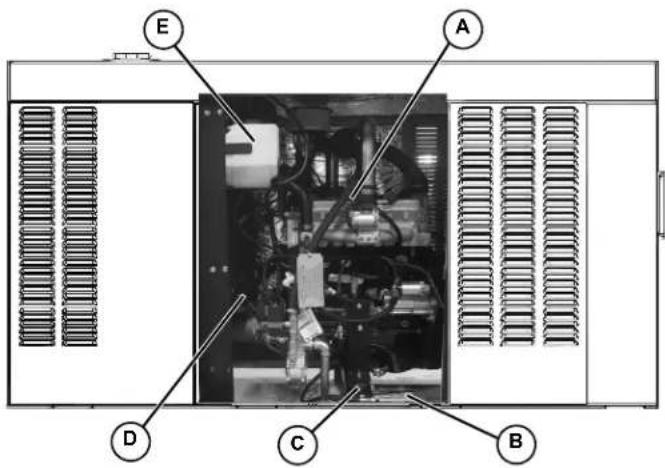
text_image
E A D C B| A Spark Plugs |
| B Battery |
| C Oil Drain Hose |
| D Coolant Drain |
| E Coolant Overflow Reservoir |
Figure 5-3. Left Side View
NOTE: All normal maintenance and service items are easily accessible for consumer convenience. Wherever possible, touch points are colored orange to provide for quick and easy recognition.
Access Panels
Access panels are located at both the left and right sides of the enclosure.
Removal
- Insert key (B) into latch and rotate counterclockwise 1/2 turn. See Figure 5-4.
- Raise pa nel using thumb latch (A).
natural_image
Close-up of a black mechanical component with a curved arm and labeled parts (A and B), no readable text or symbols beyond labels.Figure 5-4. Access Panel Key and Latch (Typical)
Installation
- Lower panel into position using thumb latch.
- Inser t key into latch and rotate clockwise 1/2 turn.
Maintenance
Regular maintenance will improve performance and extend engine/equipment life. Generac Power Systems, Inc. recommends that all maintenance work be performed by an Independent Authorized Service Dealer (IASD). Regular maintenance, replacement, or repair of the emissions control devices and systems may be performed by any repair shop or person of the owner's choosing. To obtain emissions control warranty service free of charge, the work must be performed by an IASD. See the emissions warranty.
WARNING
Equipment damage. Only qualified service personnel may install, operate, and maintain this equipment. Failure to follow proper installation requirements could result in death, serious injury, and equipment or property damage. (000182a)
It is important to perform all maintenance at the interval specified in the Service Maintenance Schedule. This ensures safe and proper operation, as well as compliance with applicable emissions standards
Service Maintenance Schedule
Observe the maintenance tasks and intervals shown in the table below.
| Service | 30 HoursEngine Break In | Daily If RunningContinuously | Schedule AEveryYear or125 Hours | Schedule BEvery2 Years or250 Hours | Schedule CEvery1000 Hours |
| Check Enclosure Louvers | ●●●● | ||||
| Check Fuel Lines | ●●●● | ||||
| Check Coolant Level and Hoses | ●●●● | ||||
| Check Radiator for Clogging | ●●●● | ||||
| Check Lubricating Oil Level and Drain Hose | ●●●● | ||||
| Replace Lubricating Oil and Oil Filter | ●●●● | ||||
| Check Battery Condition/Fluid Level | ●●● | ||||
| Check/Adjust Accessory/Drive Belt Tension | ●●● | ||||
| Replace Air Filter Element | ●●● | ||||
| Drain/Flush Coolant System | ● | ● | |||
| Clean/Gap/Replace Spark Plugs | ● | ● | |||
| Replace Timing Belt (2.4L Engines Only) | ● | ||||
| Tighten Critical Fasteners | ● |
NOTE: If the unit reaches a Schedule A or Schedule B maintenance interval with 900 to 999 total hours, have an Independent Authorized Service Dealer perform the Schedule C maintenance tasks as well (and reset the A-B-C/Year maintenance schedule counter).
Remove From Service
To ensure safety, follow the steps below prior to inspection, maintenance or service.
IMPORTANT NOTE: If currently experiencing a utility outage, see Removal From Service During Utility Outages for special instructions.
- Open the viewing window. See Open Viewing Window.
- See Figure 5-5. Move the Main Circuit Breaker switch down to the OFF (Open) position (A).
- Verify both auxiliary shutdown switches are OFF (O).
- Press OFF on the control panel (B). A red LED illuminates to confirm that the system is in the OFF mode.
- Remove T1 fuse from transfer switch.
- Pull up rubber flap (C) covering fuse holder and remove 7.5 amp fuse.
WARNING
Accidental Start-up. Disconnect the negative battery cable, then the positive battery cable when working on unit. Failure to do so could result in death or serious injury. (00013)
- Disconnect NEGATIVE battery cable.
- Place a DO NOT OPERATE tag or placard on both the control panel and transfer switch.
- If the unit has been running, wait five minutes for the engine to cool.

text_image
OFF PUSH TO TRIP A C T2 AMP AUTO MANUAL OFF B ENTER BSCAPE 006374Figure 5-5. Generator Control Panel
30 Hour Break-In
Perform the following task:
- Replace Lubricating Oil and Oil Filter
NOTE: See Replace Lubricating Oil and Oil Filter under Schedule A Maintenance.
Daily Maintenance
Perform the following tasks:
- Check Enclosure Louvers
- Check Fuel Lines
- Check Coolant Level and Hoses
- Check Radiator for Clogging
- Check Lubricating Oil Level and Drain Hose
NOTE: See Check Enclosure Louvers through Check Coolant Level and Hoses under Schedule A Maintenance.
Schedule A Maintenance
NOTE: Perform Schedule A maintenance once each year or after 125 hours of service, whichever comes first.
The 2.4L (32 kW) unit is depicted in the artwork used in this manual. For the general location of components in all other models, see Figure 5-9.
Schedule A Maintenance Item Locations
NOTE: The side of the enclosure with the viewing window is identified as the rear of the generator set. The right and left sides are identified by standing at the rear and looking towards the front of the unit.
| Model | 22/27 kW | 25/30 kW | 32/38 kW | 36/45 kW | 48 kW | 60 kW |
| Engine | 2.4L | 1.5L | 2.4L | 2.4L | 5.4L | 2.4L |
| Coolant Overflow Reservoir | L | L | L | L | L | L |
| Oil Dipstick | R | R | R | R | L | R |
| Oil Drain Hose | L | R | L | L | R | L |
| Oil Filter | R | R | R | R | L | R |
| Oil Fill Cap | E | E | E | E | R | E |
| Oil Supply Tank Fill Cap | - | - | - | TL | - | TL |
| Battery | L | R | L | L | R | L |
| Fan Belt | E | E | E | E | E | E |
| Air Filter Element | L | R | L | L | E | L |
| R = Right Side L = Left Side E = Either Side T = Top - = Not Applicable | ||||||
Preliminary Instructions
- See Remove From Service.
- Remove left and right side access panels. See Access Panels.
- Remove negative battery cable (black) from negative (-) battery terminal.
Check Enclosure Louvers
- Verify that intake and exhaust louvers and openings are clean and unobstructed. Keep clear of leaves, grass, snow, and debris.
- Wipe exterior surfaces clean using a damp cloth.
- Loosen dirt, oil, etc. with a soft bristle brush.
- Remove loose dirt and debris using a vacuum cleaner, or low pressure compressed air (not exceeding 25 psi (172 kPa).
NOTE: Periodically wash and wax enclosure using automotive type products. Frequent washing is recommended in salt water/coastal areas.
Check Fuel Lines
- Check fuel lines for leaks. Tighten fittings and clamps if necessary.
- Check fuel lines for nicks, dents, kinks, or other damage. Replace as necessary.
Check Coolant Level and Hoses

WARNING
Risk of burns. Allow engine to cool before draining oil or coolant. Failure to do so could result in death or serious injury.
(000139)
- Verify that the coolant level is between the HOT and COLD marks on the overflow reservoir. See Figure 5-6.
NOTE: Coolant expands when hot, so the level may be higher than the HOT mark. Do not add coolant higher than the HOT mark.
- If the coolant level is below the COLD mark, remove fill cap from overflow reservoir and add coolant. See Coolant Water Treatment.
- Check coolant hoses for leaks. Tighten hose clamps, if necessary.
- Check hoses for nicks, cuts, tears or general deterioration. Replace as necessary.

natural_image
Close-up of a white plastic electrical box with a black clip, mounted on a black cable (no visible text or symbols)
text_image
XO XO XO XO COLDFigure 5-6. Coolant Overflow Reservoir
Check Radiator for Clogging
- Use a flashlight to inspect the radiator fins.
- L ook for debris, accumulations of dirt, or other deposits.
- Car efully remove any debris from radiator fins. Use warm soapy water and a soft bristled remove dirt and other deposits, if necessary. 15.
Check Lubricating Oil Level and Drain Hose
NOTE: If changing engine lubricating oil and filter, see Replace Lubricating Oil and Oil Filter.
- If the engine was running, allow at least 10 minutes to elapse to ensure that the oil has fully drained into the oil pan.
NOTE: The most accurate oil level readings are obtained when the engine is cold.
- Rem ove the dipstick (B) and wipe dry with a clean, lint free cloth. See Figure 5-7.
- Slowly inser t the dipstick into the dipstick tube.
- V erify that the dipstick is fully seated in the dipstick tube.
NOTE: Some dipsticks require more effort to fully seat than others.
- Allo w at least 10 seconds to elapse.
- Slowly re move the dipstick.
- Verify that the oil level is at or near the FULL mark (A). Add oil as necessary (C).
NOTE: Observe the oil level on both sides of the dipstick. The lower of the two readings is the correct oil level measurement.
- If necessary, remove the oil fill cap and slowly add oil. Do not fill above "FULL" mark on dipstick.
- Install dips tick and oil fill cap.
- Install battery negative cable (black) onto battery negative (-) terminal.
-
Pull up rubber flap covering fuse holder and install 7.5 amp fuse.
-
Press MANUAL on the control panel to start the engine.
- Allow the engine to run for one minute.
- Press OFF on the control panel to shut down the engine. A red LED illuminates to confirm that the system is in the OFF mode.
- Return to step 1.
NOTE: The most common reasons for inaccurate oil level readings are:
- Reading the dipstick before the oil has fully drained into the oil pan.
- Inserting and removing the dipstick too quickly.
- Reading the dipstick when it has not been fully seated in the dipstick tube.
-
Reading only the high level side of the dipstick.
-
Check oil drain hose for leaks. Check hose for nicks, cuts, tears or general deterioration. Replace as necessary.
- Pull up rubber flap covering fuse holder and remove 7.5 amp fuse.
- Remove battery negative cable (black) from battery negative (-) terminal.
NOTE: On 36 kW, 45 kW, and 60 kW models, check the level of oil in the clean oil supply tank. Add clean oil as necessary. For more information, see Lube Oil Maintainer System.
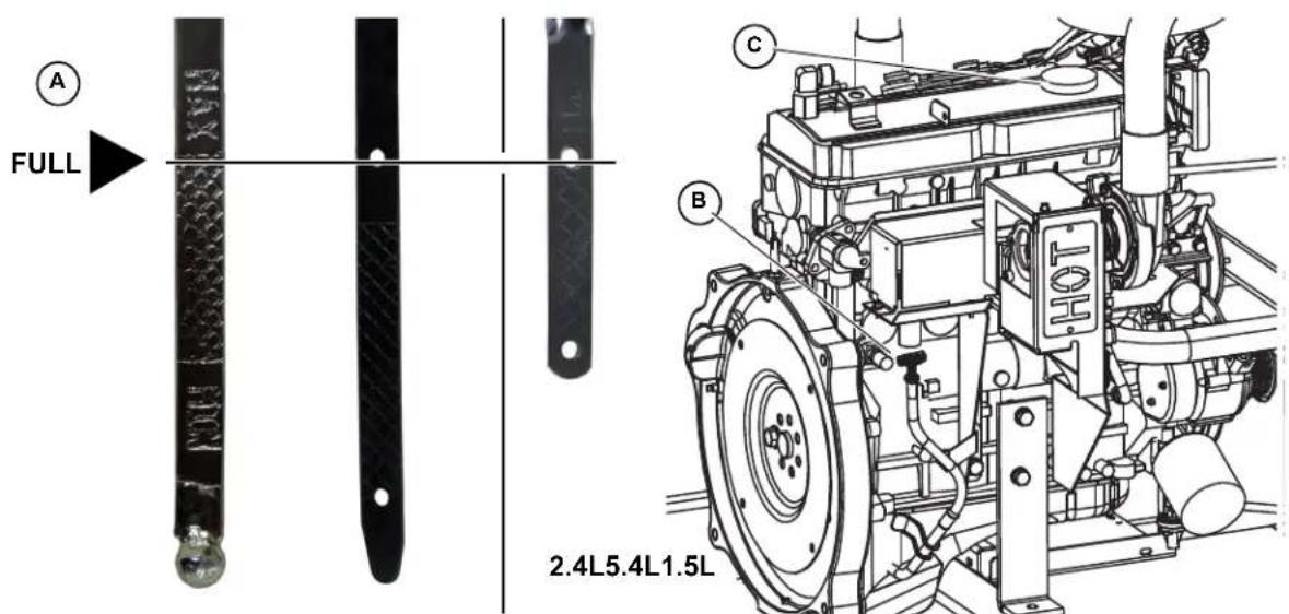
text_image
FULL 2.4L5.4L1.5LFigure 5-7. Oil Level Dipstick and Oil Fill Cap
Replace Lubricating Oil and Oil Filter
NOTE: On 36 kW, 45 kW, and 60 kW models, close shutoff valve to avoid draining the oil supply tank with the crankcase oil. For more information, see Lube Oil Maintainer System.
-
Rem ove oil drain hose from holding clamp (A). See Figure 5-8.
-
Use one wrench to hold hex on hose fitting (to prevent rotation), and use second wrench to remove drain plug.

WARNING
Risk of burns. Allow engine to cool before draining oil or coolant. Failure to do so could result in death or serious injury.
(000139)
Skin irritation. Avoid prolonged or repeated contact with used motor oil. Used motor oil has been shown to cause skin cancer in laboratory animals. Thoroughly wash exposed areas with soap and water.
(000210)
-
Drain oil into a suitable container.
-
In stall drain plug onto end of oil drain hose.
-
Insta II oil drain hose into holding clamp.
-
Rotate oil filter counterclockwise to remove from oil filter adapter (B). See Figure 5-8.
-
App ly a light coat of clean engine oil to gasket of new oil filter.
-
Insta II oil filter by hand until gasket just contacts oil filter adapter. Tighten oil filter an additional 3/4 to one full turn.
-
Remov e fill cap and fill engine with the recommended quantity and type of oil. See Engine Oil Recommendations. Crankcase oil capacity is listed below:
| Lubrication System Capacity (Oil Pan Including Oil Filter) | ||||||
| Model | 22/27 kW | 25-30 kW | 32/38 kW | 36/45 kW | 48 kW | 60 kW |
| Engine | 2.4L | 1.5L | 2.4L | 2.4L | 5.4L | 2.4L |
| 4.0 quarts (3.8 liters) | • | • | • | • | ||
| 6.0 quarts (5.7 liters) | • | |||||
| 5.25 quarts (5 liters) | • | |||||
-
Install fill cap.
-
Install negative battery cable (black) onto negative (-) battery terminal.
-
Pull up rubber flap covering fuse holder and install 7.5 amp fuse.
-
Press MANUAL on the control panel to start the engine.
- Allow the engine to run for one minute. Check for leaks while the engine is running.
- Press OFF on the control panel. A red LED illuminates to confirm that the system is in the OFF mode.
-
Wait ten minutes for the engine to cool and to allow oil to drain back to the oil pan.
-
Check oil level and add oil as necessary. See Check Lubricating Oil Level and Drain Hose.
- Install fill cap.
NOTE: On 36 kW, 45 kW, and 60 kW models, open shutoff valve to enable Lube Oil Maintainer System.
NOTE: Dispose of used oil and oil filter at a proper collection center.
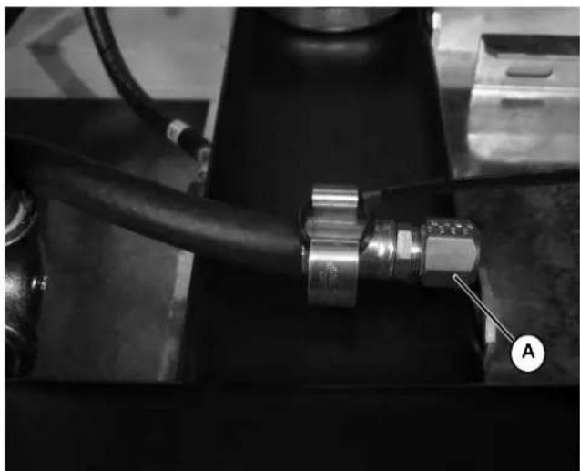
natural_image
Close-up of a mechanical assembly with a black pipe fitting and a labeled component (A), no visible text or symbols.
natural_image
Technical line drawing of a mechanical assembly with labeled component B (no text or symbols beyond label)Figure 5-8. Oil Drain Hose, Fill Cap, Dipstick and Filter
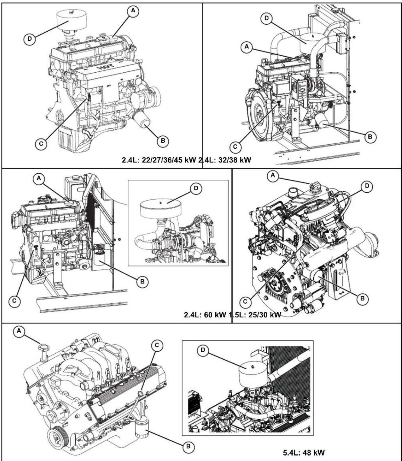
Figure 5-9. Engine Oil and Air Cleaner Maintenance (All Models)
| A Oil Fill Cap |
| B Oil Filter |
| C Oil Level Dipstick |
| D Air Cleaner |
Check Battery Condition/Fluid Level
Check Condition and Clean
- See Figure 3-3 for illustration. Verify top of battery is clean and dry. Dirt and electrolyte on top of the battery can cause battery to self-discharge. Clean battery top with a solution of baking soda (sodium bicarbonate) and water (5 teaspoons baking soda per quart or liter of water). When solution stops bubbling, rinse off the battery with clean water.
- Clea n cable clamps and battery terminals using a wire brush or sandpaper to remove any oxidation.
- Inspect battery screws, clamps and cables for breakage, loose connections and corrosion. Tighten and clean as necessary.
- Check the battery posts for melting or damage caused by over tightening.
- Inspect battery for discoloration, raised top or a warped or distorted case, which might indicate that the battery has been frozen, overheated, or overcharged.
- Inspec t the battery case for cracks or leaks.
- Check the battery fluid level of unsealed batteries. See Check Fluid Level.
- Check the battery state of charge. See Check State of Charge.
- Rep lace battery if necessary. See Battery Replacement.
Check Fluid Level
Check the fluid level of unsealed batteries. If necessary, fill with distilled water only. DO NOT use tap water.
Check State of Charge
Check the state of charge using a Digital Multimeter. Recharge and retest if state of charge is below manufacturer's recommendations. Replace battery if necessary.
Battery Replacement
Removal

!WARNING
Electrical shock. Disconnect battery ground terminal before working on battery or battery wires. Failure to do so could result in death or serious injury. (000164)
WARNING
Accidental Start-up. Disconnect the negative battery cable, then the positive battery cable when working on unit. Failure to do so could result in death or serious injury. (000130)
- Remove negative battery cable (black) (B) from negative (-) battery terminal.
- Remo ve positive battery cable (red) (A) from positive (+) battery terminal.
- See Figure 5-10. Install rubber protective cover over positive (+) battery terminal (A).
- Lo osen two screws with nylon washers to release battery hold-down clamp from battery tray.
- Gr asp battery strap (B), and lift battery from battery tray.
- Remo ve rubber protective cover from positive (+) battery terminal.
Installation
WARNING
Accidental Start-up. Disconnect the negative battery cable, then the positive battery cable when working on unit. Failure to do so could result in death or serious injury. (000130)
- Install rubber protective cover over positive (+) battery terminal (A).
- Gr asp battery strap (B) and lift battery.
- Set battery onto battery tray.
- T ighten two screws with nylon washers to secure hold-down clamp to battery tray.
- Remo ve rubber protective (A) cover from positive (+) battery terminal.
- Install positive battery cable (red) to positive (+) battery terminal.
- Insta II negative battery cable (black) to negative (-) battery terminal.
NOTE: If continuing with Schedule A maintenance procedures, leave the battery negative cable (black) disconnected.
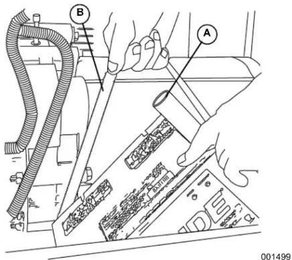
text_image
Technical diagram showing hands operating a mechanical device with labeled parts A and B, including a cable and component assembly.Figure 5-10. Remove/Install Battery
- Reche ck belt deflection and repeat steps as necessary.
Check and Adjust Accessory/Drive Belt
Check
Check the accessory/drive belt condition.
- Per form visual inspection as follows:
- Inspect belt for cracks, fraying, excessive wear or other damage.
- Verify belt is free of grease and oil.
- Replace belt if contaminated, damaged, frayed or worn.
NOTE: Use a solution of soap and warm water to clean pulleys, if necessary. Avoid use of solvents, but if used, always follow by a soap and water wash.
- Check the fan belt deflection. Adjust the belt deflection as follows:
- Using a suitable gauge, apply 22 lbs (10 kgf) force midway between the water pump and alternator pulleys. See Figure 5-11.
NOTE: 5.4 L (48 kW) units are provided with an automatic belt tensioner and do not need adjustment.
• Take note of gauge reading. If belt deflection is not within specification, see Adjust.
| Belt Deflection | English | Metric |
| 3/8 - 5/8 in | 7.6 - 12.7 mm |
Adjust
- Loosen DC alternator tension bracket screw. Rotate alternator outward to reduce belt deflection, rotate inward to increase belt deflection.
- T ighten DC alternator tension bracket screw to 17-22 ft-lbs (23-30 Nm).
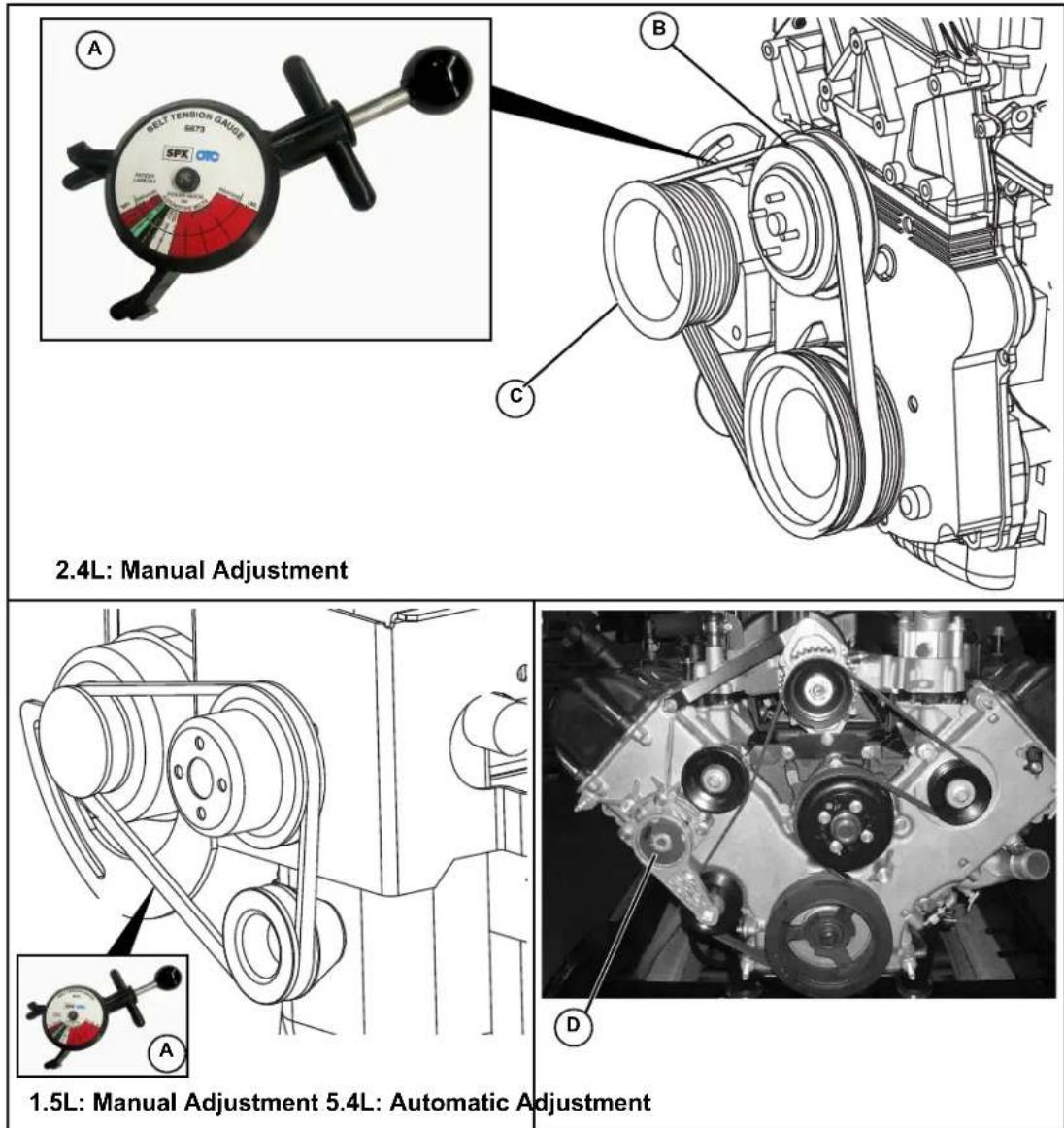
Figure 5-11. Check Accessory/Drive Belt Deflection
| A Belt Deflection gauge |
| B Water Pump Pulley |
| C Alternator Pulley |
| D Automatic Tensioner |
Replace Air Filter Element
- Remove wing nut (B), lock washer (C), and flat washer (D) from threaded rod to release air cleaner cover. See Figure 5-12.
- Rem ove the air filter element (A) and discard.
-
Th oroughly clean air cleaner cover of any dust, dirt, or debris.
-
Place ne w air filter element against adapter flange.
NOTE: The air filter element is not directional.
- Insta II air cleaner cover (E) over threaded rod. Install flat washer, lock washer and wing nut. Tighten wing nut until snug.
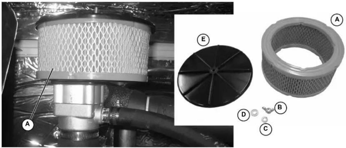
natural_image
Technical illustration of a mechanical component with labeled parts (A, B, C, D, E), showing internal structure and assembly details (no readable text or symbols beyond labels)Figure 5-12. Air Cleaner Cover and Filter Element
NOTE: Service kits are available from Independent Authorized Service Dealers.
Final Instructions
If only performing Schedule A maintenance procedures, proceed as follows:
- Install battery negative cable (black) onto battery negative (-) terminal.
- Install left and right side access panels. See Access Panels.
- See Return To Service.
Schedule B Maintenance
NOTE: Perform Schedule B maintenance every two years or after 250 hours of service, whichever comes first. Before proceeding below, first perform all tasks listed under Schedule A Maintenance.
NOTE: The 2.4L (32 kW) unit is depicted in the artwork used in this manual. For the general location of components in all other models, see Schedule B Maintenance Item Locations.
Schedule B Maintenance Item Locations
NOTE: The side of the enclosure with the viewing window is identified as the rear of the generator set. The right and left sides are identified by standing at the rear and looking towards the front of the unit.
| Model | 22/27 kW | 25/30 kW | 32/38 kW | 36/45 kW | 48 kW | 60 kW |
| Engine | 2.4L | 1.5L | 2.4L | 2.4L | 5.4L | 2.4L |
| Coolant Drain Hose | L | R | L | L | R | L |
| Radiator Fill Cap | T | T | T | T | T | T |
| Coolant Overflow Reservoir | L | L | L | L | L | L |
| Spark Plugs | L | R | L | L | B | L |
| R = Right Side L = Left Side B = Both Sides T = Top | ||||||
Drain/Flush Coolant System
-
Disconnect and empty coolant overflow reservoir.
-
Install an d connect coolant overflow reservoir.

WARNING
Risk of burns. Allow engine to cool before draining oil or coolant. Failure to do so could result in death or serious injury. (000139)
-
Rotate and remove plastic cover at top of enclosure.
-
Slowly unscrew radiator cap.
-
Locate drain cock at bottom left side of radiator.
NOTE: If unit is not equipped with drain hose, install suitable length of rubber hose to drain cock.
-
Rotate hex fitting to open drain cock (A). See Figure 5-13
-
Remov e coolant drain hose from holding clamp.
-
Use wrench to hold hex on hose fitting (to prevent rotation), and use second wrench to remove drain plug.
-
Dr ain coolant into a suitable container.
-
Install plug at end of drain hose.
-
Insta II drain hose in holding clamp.
-
Rotate hex fitting to close radiator drain cock.
-
Obtain the recommended quantity and type of coolant. See Coolant Water Treatment.
| System Coolant Capacity | ||||||
| Model | 22/27 kW | 25/30 kW | 32/38 kW | 36/45 kW | 48 kW | 60 kW |
| Engine | 2.4L | 1.5L | 2.4L | 2.4L | 5.4L | 2.4L |
| 2.0 gallons (7.6 liters) | • | |||||
| 2.5 gallons (9.5 liters) | • | • | • | • | ||
| 3.0 gallons (11.4 liters) | • | |||||
- Insert funnel into filler neck of radiator (B). See Drain/Fill Coolant System.
- Slowly pour coolant into filler neck until radiator is full.
- Install radiator cap.
- Press MANUAL on the control panel to start the engine. A blue LED illuminates to confirm that the system is in the MANUAL mode.
- Allow engine to run until the thermostat opens, as indicated by heating of the top radiator hose.
- Check coolant hoses for leaks. Tighten clamps, if necessary.
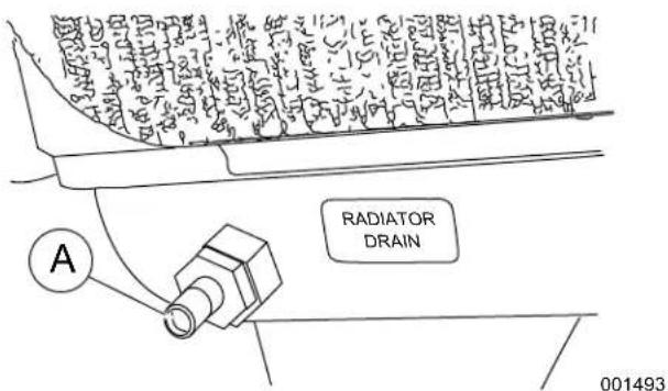
text_image
RADIATOR DRAIN 001493NOTE: Drain hose removed for illustration purposes.
- Press OFF on the control panel to shut the engine down.
- Wait for the engine to cool.
- Repeat steps 4-21 to drain and refill cooling system.
- Slowly unscrew radiator cap. Slowly pour coolant into filler neck until radiator is full.
- Add coolant to the overflow reservoir. See Check Coolant Level and Hoses.
- In stall plastic cover at top of enclosure and rotate until tight.
- Check hoses for nicks, cuts, tears or general deterioration. Replace as necessary.
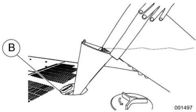
natural_image
Technical diagram of a mechanical assembly with labeled component B, showing no readable text or symbols.Figure 5-13. Drain/Fill Coolant System
Clean/Gap/Replace Spark Plugs
Clean, gap or replace spark plugs as follows:

WARNING
Electric shock. Do not disconnect spark plug wires with engine running. Doing so could result in death or serious injury.
(000140a)
- Remove battery negative cable (black) from battery negative (-) terminal.
- Rem ove spark plug cables from spark plug terminals (A). See Figure 5-14.

natural_image
Close-up of automotive engine components with hoses and connectors (no visible text or symbols)NOTE: When disconnecting spark plug cable from spark plug terminal, always grasp and pull on the boot at terminal end of the cable. Pulling on cable portion can result in parts damage.
- Th oroughly clean area around spark plugs.
- Remo ve spark plugs from cylinder head using an appropriate spark plug socket wrench.
- Check condition of threads in cylinder head and on spark plugs. If necessary, soften deposits with penetrating oil and clean out with a thread chaser.
- Clea n spark plugs using a wire brush and commercial solvent. Do not blast spark plugs. Use new spark plugs if necessary.

natural_image
Illustration of hands connecting a screw to a mechanical component labeled 'P' (no text or symbols beyond label)Figure 5-14. Adjust Spark Plug Gap
- Che ck spark plug gap using a wire feeler gauge (B). Adjust gap by carefully bending ground electrode as follows:
| Spark Plug Gap | ||||||
| Model | 22/27 kW | 25/30 kW | 32/38 kW | 36/45 kW | 48 kW | 60 kW |
| Engine | 2.4L | 1.5L | 2.4L | 2.4L | 5.4L | 2.4L |
| 0.71 mm (0.028 in.) | • | • | ||||
| 0.9 mm (0.035 in.) | • | |||||
| 1.07-1.17 mm (0.042-0.046 in.) | • | • | ||||
| 1.29-1.45 mm (0.051-0.057 in.) | • | |||||
- Finger tighten spark plugs into cylinder head, and then using a spark plug socket, tighten as follows:
| Spark Plug Torque | ||
| Engine | ft-lbs | N-m |
| 1.5L, 2.4L | 18 | 25 |
| 5.4L | 13 | 18 |
- Install spark plug cables onto spark plug terminals.
- Verify that spark plug cables are captured in cable clips at top of valve cover.
Final Instructions
If only performing Schedule A and Schedule B maintenance procedures, proceed as follows:
- Insta II battery negative cable (black) onto battery negative (-) terminal.
- Inst all left and right side access panels. See Access Panels.
- See Return To Service.
Schedule C Maintenance
NOTE: Perform Schedule C maintenance after 1000 hours of service. Before proceeding below, first perform all tasks listed under Schedule A Maintenance and Schedule B Maintenance.
IMPORTANT NOTE: The following procedures require special tools and skills. Contact an Independent Authorized Service Dealer to perform these tasks.
- Remove battery negative cable (black) from battery negative (-) terminal.
- Proceed as follows:
- Replace timing belt (2.4L engines only).
- Tighten critical fasteners.
- Replace upper and lower radiator hoses.
- Replace engine coolant bypass hoses.
- Replace block heater hoses.
NOTE: Reset the A-B-C/Year time maintenance schedule counter using the Dealer Sub Menu (password required).
- Install battery negative cable (black) onto battery negative (-) terminal.
- Install front access panel. Install left and right side access panels. See Access Panels.
- See Return To Service.
Return To Service
After inspection, maintenance or service of the generator, return the unit to service as follows:
- Pull up rubber flap covering fuse holder and install 7.5 amp fuse (A). See Figure 5-5.
- Install T1 fuse in transfer switch.
- Verify both auxiliary shutdown switches are ON (I). See Figure 3-6 for the locations.
- Press AUTO on the control panel. A green LED illuminates to confirm that the system is in the AUTO mode (B).
- Move the Main Circuit Breaker switch up to the ON (Closed) position (C).
- Close the viewing window.
- Remove the DO NOT OPERATE tag or placard from both the control panel and transfer switch.
- Reset the time and date.
Lube Oil Maintainer System
Description
NOTE: Oil reservoir is empty when shipped from factory. Fill with clean engine oil to activate the system.
The 36 kW, 45 kW, and 60 kW models are equipped with a Lube Oil Maintainer System. The system is installed at the factory and calibrated at the factory to the correct engine-running crankcase oil level. As needed, the system keeps the engine lubricating oil full by automatically adding clean oil from the oil supply tank.
NOTE: The Lube Oil Maintainer System is equipped with three wires (red, white, black) which are not used in this unit.
See Figure 5-15. The green bar (A) observed through the viewing lens (B) shows the normal oil level operating range of the Lube Oil Maintainer Regulator during engine running operation. When the oil level is within the green bar, the internal float holds the inlet valve closed to keep the crankcase oil at the current level.
As the engine uses oil, the float drops to open the inlet valve and allow clean oil to be supplied to the crankcase, replenishing engine oil to the full mark indicated on the oil dipstick. The float then rises with the crankcase oil level until it reaches a point where the inlet valve closes.
When the oil level as observed through the viewing lens is below the normal operating range green bar, it is an indication that the oil supply tank is low or the oil inlet screen is clogged (C).
NOTE: It is normal for the oil level to be above the normal operating range green bar (D) when engine is not running.
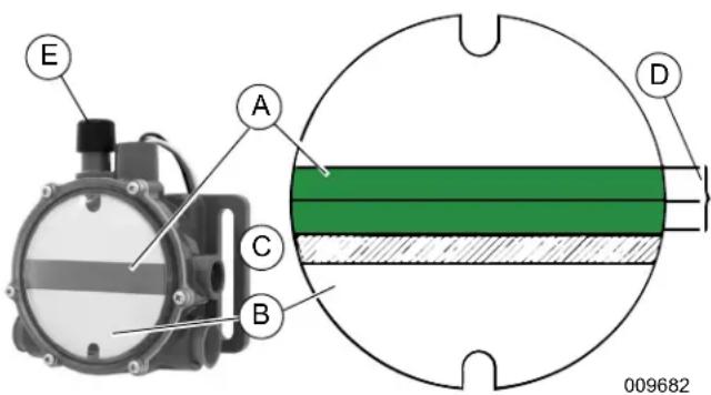
text_image
E A C B D 009682Figure 5-15. Lube Oil Maintainer Regulator
NOTE: When changing engine oil, always close the shutoff valve to avoid draining the clean oil in the oil supply tank with the crankcase oil. See Figure 5-9.
Fill Oil Supply Tank
- Rotate plastic cover counter-clockwise and remove from top of enclosure. See Figure 5-17.
- Remove fill cap at top of oil supply tank (Figure 5-18).
- Add clean engine oil to oil supply tank (2-1/2 gallons [9.46 liters] capacity).
- Install fill cap at top of oil supply tank.
- Install plastic cover at top of enclosure and rotate clockwise until tight.
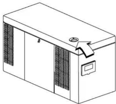
natural_image
Line drawing of a rectangular industrial machine with ventilation grilles and a handle (no text or symbols)Figure 5-16. Access Oil Supply Tank
009678
Test Functionality
See Figure 5-15. Momentarily press the test button (E) to confirm that the float is operating correctly.
NOTE: Do not hold the test button down for a prolonged period of time or the crankcase can be over filled. Over filling the crankcase can result in engine damage.
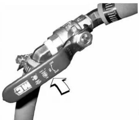
natural_image
Close-up of a mechanical device with a labeled component and an arrow pointing to it (no readable text or symbols)009681
Figure 5-17. Shutoff Valve (Shown in Open Position)
Shutoff Valve
See Figure 5-17 and Figure 5-18. When draining engine crankcase oil, always close shutoff valve to avoid draining clean oil from supply tank.
After filling crankcase with clean oil, remember to open shutoff valve to enable operation of Lube Oil Maintainer System.
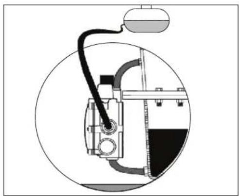
natural_image
Technical diagram of a mechanical device inside a circular frame, showing internal components and wiring (no text or labels)
natural_image
Technical line drawing of a mechanical device with internal components and external wiring (no text or symbols)001756
Figure 5-18. Lube Oil Maintainer Assembly and Function Diagram
| A | Oil Inlet Hose | F | Test Button | L | Regulator |
| B | Regulator Viewing Lens | G | Running Engine Crankcase | M | Shutoff Valve |
| C | Center of Green Bar | H | Oil Level | N | 2-1/2 Gallon Oil Supply Tank |
| D | Crankcase Hose | J | Engine Crankcase Oil Pan | O | Fill Cap |
| E | Oil Supply Tank | K | Oil Drain Hose | — | — |
This page intentionally left blank.
Section 6: Troubleshooting
Engine Troubleshooting
| Problem Cause Correction | ||
| The engine will not crank. | Fuse blown. | Replace 7.5 amp fuse in generator control panel. Correct short circuit condition if fuse blows again. |
| Loose, corroded or defective, battery cables. | Tighten, clean or replace as necessary.* | |
| Defective starter contact. | Tighten, clean or replace as necessary.* | |
| Defective starter motor. | Tighten, clean or replace as necessary.* | |
| Dead Battery. Charge or replace battery. | ||
| The engine cranks but will not start. | Out of fuel. Replenish fuel. Turn on fuel valve. | |
| Defective fuel solenoid. * | ||
| Open F1 7.5 amp fuse. | Replace F1 7.5 amp fuse if fuse blows again.* | |
| Open F2 15 amp fuse. | Replace F2 15 amp fuse if fuse blows again.* | |
| Defective fuel system. * | ||
| No fuel supply. Turn on fuel supply.* | ||
| The engine starts hard and runs rough. | Air cleaner plugged or damaged. Check/replace air cleaner. | |
| The generator is set to OFF, but the engine continues to run. | Defective keypad. | * |
| Defective control board. | * | |
| There is no AC output from the generator. | Main line circuit breaker is in the OFF (OPEN) position. | Reset circuit breaker to ON (CLOSED) position. |
| Generator internal failure. | * | |
| There is no transfer to standby after utility source failure. | Defective transfer switch coil. | * |
| Defective transfer relay. | * | |
| Transfer relay circuit open. | * | |
| Defective control logic board. | * | |
| Unit consumes large amounts of oil. | Engine over filled with oil. | Adjust oil to correct level. |
| Engine breather defective. | * | |
| Incorrect oil type or viscosity. | See Engine Oil Recommendations. | |
| Damaged gasket, seal, or hose. | Check for oil leaks. | |
| * Contact an Independent Authorized Service Dealer for assistance. | ||
Controller Troubleshooting
| Active Alarm Problem Solution | ||
| NOT ACTIVATED | Unit will not start in AUTO with utility loss. | Refer to activation section in Owner's Manual. |
| NONE Unit running | in AUTO but no power in house. | Check MLCB. Contact Independent Authorized Service Dealer (IASD) if MLCB is in the ON position. |
| NONE Unit will not start in AUTO with utility loss. | Check screen for start delay countdown. If the start up delay is greater than expected, contact IASD to adjust from 2 to 1500 seconds. | |
| HIGH TEMPERATURE | Unit shuts down during operation. | Check ventilation around the intake, exhaust and rear of generator. Contact IASD if no obstruction is found. |
| OVERLOAD Unit shuts down during operation. | Clear alarm and remove loads from the generator. Put back in AUTO and restart. | |
| RPM SENSE LOSS | Unit was running and shuts down, attempts to restart. | Clear alarm and remove loads from the generator. Put back in AUTO and restart. If problem returns, contact IASD to investigate possible fuel issue. |
| LOW OIL PRESSURE | Unit will not start in AUTO with utility loss. | Check oil level. Add oil per Owner's Manual. Contact IASD if oil level is correct. |
| RPM SENSE LOSS Unit will not start in AUTO with utility loss. | Clear alarm. From the MAIN menu on the control panel, navigate to the BATTERY MENU. Contact IASD if battery is GOOD. Replace battery If CHECK BATTERY is displayed. | |
| OVERCRANK Unit will not start in AUTO with utility loss. | Clear alarm. Attempt to start the unit in MANUAL. If it does not start or starts and runs rough, contact IASD. | |
| OVERSPEED | Unit will not start in AUTO with utility loss. | Contact IASD. |
| UNDER VOLTAGE | Unit will not start in AUTO with utility loss. Contact IASD. | |
| UNDERSPEED | Unit will not start in AUTO with utility loss. | Contact IASD. |
| MISWIRE Unit will not start in AUTO with utility loss. Contact IASD. | ||
| OVERVOLTAGE | Unit will not start in AUTO with utility loss. | Contact IASD. |
| LOW BATTERY | Warning active. | Clear alarm. From the MAIN menu on the control panel, navigate to the BATTERY MENU. Contact IASD if battery is GOOD. Replace battery If CHECK BATTERY is displayed. |
| BATTERY PROBLEM | Warning active. | Contact IASD. |
| CHARGER WARNING | Warning active. | Contact IASD. |
| SERVICE SCHEDULE A | Warning active. | Perform SERVICE SCHEDULE A maintenance; press ENTER to clear. |
| SERVICE SCHEDULE B | Warning active. | Perform SERVICE SCHEDULE B maintenance; press ENTER to clear. |
| SERVICE SCHEDULE C | Warning active. | Perform SERVICE SCHEDULE C maintenance; press ENTER to clear. |
| AUXILIARY SHUTDOWN | Unit will not start in AUTO with utility loss. | Verify both auxiliary shutdown switches are ON (I). See Figure 3-6 for the locations. |
Removal From Service During Utility Outages
If, during prolonged utility outages, the user wishes to remove the unit from service to conserve fuel, reduce run hours, or to perform maintenance tasks, then complete the steps listed below.
IMPORTANT NOTE: Failure to abide by this procedure can result in equipment damage.
To remove the generator from service while running in AUTO and online, proceed as follows:
- Turn the main utility disconnect to OFF (Open).
- Open the viewing window. See Open Viewing Window.
- Move the Main Circuit Breaker switch down to the OFF (Open) position.
- Press OFF on the control panel. A red LED illuminates to confirm that the system is in the OFF mode.
NOTE: If inspection and/or maintenance tasks are to be performed, complete the additional steps listed below.
- Remove T1 fuse from transfer switch.
- Pull up rubber flap covering fuse holder and remove 7.5 amp fuse.
- Remove battery negative cable (black) from battery negative (-) terminal.
- Place a DO NOT OPERATE tag or placard on both the control panel and transfer switch.
To return the generator to service, proceed as follows:
NOTE: If inspection and/or maintenance tasks were performed, start with step 1. If the unit was just shut down to conserve fuel or to reduce run hours, start at step 5.
-
Install battery negative cable (black) onto battery negative (-) terminal.
-
Pull up rubber flap covering fuse holder and install 7.5 amp fuse.
-
Install T1 fuse in transfer switch.
-
Remove the DO NOT OPERATE tag or placard from both the control panel and transfer switch.
-
Press AUTO on the control panel. A green LED illuminates to confirm that the system is in the AUTO mode. Allow the generator to start and run for a few minutes.
-
Move the Main Circuit Breaker switch up to the ON (Closed) position.
-
Turn the main utility disconnect to ON (Closed).
-
Close the viewing window.
Storage
Prepare For Storage
If the generator cannot be exercised every seven days and will be out of service longer than 90 days, prepare for storage as follows:
- Open the viewing window. See Open Viewing Window.
- Press MANUAL on the control panel to start the engine. A blue LED illuminates to confirm that the system is in the MANUAL mode.
- Allow the engine to run until it reaches normal operating temperature.
- Press OFF on the control panel. A red LED illuminates to confirm that the system is in the OFF mode.
- Move the Main Circuit Breaker switch on the control panel down to the OFF (Open) position.
- Pull up rubber flap covering fuse holder and remove 7.5 amp fuse.
- Turn off utility power to the transfer switch.
- Place a DO NOT OPERATE tag or placard on both the control panel and transfer switch.
- Wait five minutes for the engine to cool.
- Remove left and right side access panels. See Access Panels.
NOTE: On 36 kW, 45 kW, and 60 kW models, close shutoff valve to avoid draining the oil supply tank with the crankcase oil. For more information, see Lube Oil Maintainer System.
- Remove oil drain hose from holding clamp.
- Use one wrench to hold hex on hose fitting (to prevent rotation), and use second wrench to remove drain plug.
- Drain oil into a suitable container.
- Install drain plug onto end of oil drain hose.
- Install oil drain hose into holding clamp.
- Rotate oil filter counterclockwise to remove from oil filter adapter.
- Apply a light coat of clean engine oil to gasket of new oil filter.
- Install oil filter by hand until gasket just contacts oil filter adapter. Tighten oil filter an additional 3/4 to one full turn.
- Remove oil fill cap and fill engine with the recommended oil. See Engine Oil Recommendations.
- Install oil fill cap.
NOTE: Dispose of used oil and oil filter at a proper collection center.
WARNING
Explosion. Batteries emit explosive gases. Always disconnect negative battery cable first to avoid spark. Failure to do so could result in death or serious injury. (000238)
- Remove battery negative cable (black) from battery negative (-) terminal.
- Remove battery positive cable (red) from battery positive (+) terminal.
- Remove two screws to release battery hold clamp from platform.
- Remove battery and store in a cool, dry room.
- Install left and right side access panels. See Access Panels.
- Thoroughly clean and wipe down the generator. See Corrosion Protection.
Return From Storage
To return the unit to service after storage, proceed as follows:
- Thoroughly clean and wipe down the generator. See Corrosion Protection.
- Remove left and right side access panels. See Access Panels.
- Install battery onto tray oriented with the negative (-) post toward the front of the enclosure.
- Install two screws with nylon washers to secure battery hold-down clamp to tray.
- Check battery. See Check Battery Condition/Fluid Level.
WARNING
Explosion. Batteries emit explosive gases. Always connect positive battery cable first to avoid spark. Failure to do so could result in death or serious injury. (000133)
- Install battery positive cable (red) onto battery positive (+) terminal.
- Install battery negative cable (black) onto battery negative (-) terminal.
- Check oil level and add oil as necessary. DO NOT OVERFILL.
NOTE: On 36 kW, 45 kW, and 60 kW models, open shutoff valve to enable Lube Oil Maintainer System.
- Open the viewing window. See Open Viewing Window.
-
Pull up rubber flap covering fuse holder and install 7.5 amp fuse.
-
Move the Main Circuit Breaker switch up to the ON (Closed) position.
- Press MANUAL on the control panel to start the engine. A blue LED illuminates to confirm that the system is in the MANUAL mode.
- Allow the engine to run until it is reaches normal operating temperature. Check for leaks while the engine is running.
- Press OFF on the control panel. A red LED illuminates to confirm that the system is in the OFF mode.
- Install left and right side access panels. See own Access Panels.
- Turn on utility power to the transfer switch.
- Press AUTO on the control panel. A green LED illuminates to confirm that the system is in the AUTO mode.
- Reset the time and date.
- Close the viewing window.
Attention After Submersion
Do NOT start and operate the generator if it has been submerged in water. Have an Independent Service Dealer thoroughly clean, dry, and inspect the generator following any submersion. If the structure (home) has been flooded, it should be inspected by a certified electrician to ensure there won't be any electrical problems during generator operation or when utility power is returned.
Part No. 0K8185
Rev. D 05/28/2019
©2019 Generac Power Systems, Inc.
All rights reserved
Specifications are subject to change without notice.
No reproduction allowed in any form without prior written
consent from Generac Power Systems, Inc.
GENERAC®
Generac Power Systems, Inc.
S45 W29290 Hwy. 59
Waukesha, WI 53189
1-888-GENERAC (1-888-436-3722)
www.generac.com