
1030850 - Beer Tap Perlick - Free user manual and instructions
Find the device manual for free 1030850 Perlick in PDF.

| Product Type | Nitro Beverage Dispensing Kit (Dual Infuser) |
| Model Number | 1030850 |
| Brand | Perlick |
| Number of Infusers | 2 (Dual) |
| Compatible Beverages | Nitro coffee, cold brew, and other nitrogen-infused drinks |
| Gas Type | Nitrogen (N2) |
| Recommended Gas Pressure | 28-32 PSI |
| Included Components | Dual nitrogen infuser, 6-way air distributor, twin-gauge regulator, 30 ft red gas line, 5 ft beverage tubing (5 pieces), 4 gray gas disconnects, 4 black liquid disconnects, air scoop, snorkel tubing, mounting templates, tapping parts bag (includes clamps, screws, wrench, etc.) |
| Input Connections | Ball-lock quick disconnects: gray for gas, black for liquid |
| Output Connections | Beverage lines to tower/faucet |
| Control Feature | Nitrogen Control System (NCS) dial for adjusting infusion level |
| Installation Time | 1.5 to 2 hours per install |
| Required Tools | 1/4" hex-nut driver, Teflon tape, 5/16" hex bit, safety glasses, 5/32" drill bit, mallet, large adjustable wrench, hand drill, torpedo level, measuring tape, gloves, optional needle nose pliers and ear clamp pliers |
| Safety Features | Safety chain for tank, pressure relief valve on keg, warning against excess bend radius |
| Cleaning Instructions | Flush lines with water, use cleaning chemical for cold beverage systems, soak stout nozzle in carbonated water, pH test rinse water |
| Warranty | 1 year limited warranty on nitrogen infuser; 90-day warranty on replacement parts |
| Regulatory Compliance | California Prop 65 warning (chromium) |
| Service Parts Available | Quick disconnects, tubing, air distributor, regulator, air scoop, etc. (see manual for part numbers) |
Frequently Asked Questions - 1030850 Perlick
User questions about 1030850 Perlick
0 question about this device. Answer the ones you know or ask your own.
Ask a new question about this device
Download the instructions for your Beer Tap in PDF format for free! Find your manual 1030850 - Perlick and take your electronic device back in hand. On this page are published all the documents necessary for the use of your device. 1030850 by Perlick.
USER MANUAL 1030850 Perlick
INSTALLATION AND OPERATION INSTRUCTIONS
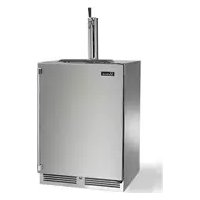
PERLICK NITRO BEVERAGE DISPENSING KIT (SINGLE AND DUAL INFUSERS)

natural_image
Interior view of a stainless steel water control cabinet with two gas cylinders and two side handles (no visible text or symbols)PRODUCT NUMBERS
RS-NDK
1030849 (Single)
1030850 (Dual)
Scan the QR code
to watch our Nitro
Dispensing Kit Installation
video on YouTube

GENERAL INFORMATION
Introduction
Congratulations on your purchase of a Perlick Nitro Beverage Dispensing Kit. This manual has been prepared to assist you in the setup of your kit and to acquaint you with its operation and maintenance.
We dedicate considerable time to ensure that our products provide the highest level of customer satisfaction. If service is required, your dealer or customer support at techservice@partstown.com or 844-411-8050 can provide you with a list of qualified service agents. For your own protection, never return merchandise for credit without our approval.
We thank you for selecting a Perlick product and assure you of our continuing interest in your satisfaction.
Warranty
To register your product, visit our web site at www.perlick.com. Click on "Commercial", then "Service". Click on the link "Warranty Registration Form". You must complete and submit this form or the installation date will revert back to the ship date.
Please record the purchase date and the dealer's name, address and telephone number below.
Model Number: ____
Order Number: ____
Purchase Date: ____
Dealer Name & Address ____
Phone Number
Form No. Z2751
Rev. 10.25.22
TABLE OF CONTENTS
General Information....1
Safety 2
Infuser Warranty Information....3
Tool & Time Requirements 3
Preparing For Use....4
Parts List....5
RS-NDK (Single Infuser) 5
1030849 (Single Infuser) 6
1030850 (Dual Infuser) 7
Tapping Parts Bag 8
Infuser Assembly Instructions 9
Installation Operations....11
Filling The Keg 20
Line Setup Check....21
System Cleaning....23
Troubleshooting....25
Service Parts List....27
SAFETY
PLEASE READ all instructions completely before attempting to install or operate the unit. Take particular note of the DANGER, WARNING and CAUTION information in the manual. The information is important for the safe and efficient installation, operation and care of your Perlick unit.
DANGER
Indicates a hazard that WILL result in serious injury or death if
precautions are not followed.
WARNING
Indicates a hazard MAY cause serious injury or death if
precautions are not followed.
CAUTION
Indicates a hazard where minor or moderate injury may occur if
precautions are not followed.
NOTICE
Indicates that property damage may occur if warnings or
instructions are not followed.
IMPORTANT!
Read and understand all information in this manual before attempting the installation. All plumbing and electrical work must be performed by a qualified technician and conform to all applicable state and local codes.

WARNING: California Prop 65 Notice
These products may expose you to chemicals including Chromium, which are known to the state of California to cause cancer and birth defects or other reproductive harm. For more information on whether a product in this list contains these chemicals, please refer to the specific product page at perlick.com. Or to find out more about Prop 65, go to P65Warnings.ca.gov.
Perlick is committed to continuous improvement. Therefore, we reserve the right to change specifications without prior notice
ADDITIONAL INFUSER WARRANTY INFORMATION
NITROGEN INFUSER WARRANTY:
WARRANTY: Perlick warrants that for a period of one (1) year following delivery, if the nitrogen infuser belonging to kit(s) 1030849, 1030850, or RS-NDK you have purchased will (a) perform in accordance with published specifications, and (b) will be free from defects in materials or workmanship. In the event a nitrogen infuser from any of the aforementioned kit(s) does not meet this warranty, subject to the conditions set forth in these terms and conditions, Perlick's sole obligation will be, at its election, to repair or replace the nitrogen infuser in question.
PERLICK MAKES NO OTHER WARRANTIES REGARDING THE NITROGEN INFUSERS, EXPRESS OR IMPLIED, AND ALL IMPLIED WARRANTIES OF MERCHANTABILITY, NON-INFRINGEMENT AND FITNESS FOR A PARTICULAR PURPOSE ARE HEREBY DISCLAIMED. IN NO EVENT WILL PERLICK BE LIABLE FOR PUNITIVE, SPECIAL OR CONSEQUENTIAL DAMAGES, OR FOR AN AMOUNT IN EXCESS OF THE PURCHASE PRICE OF THE DEFECTIVE PERLICK PRODUCT.
NITRO INFUSER REPLACEMENT PARTS WARRANTY:
Perlick Corporation provides the following limited warranty for Perlick genuine service parts (Product) only if originally purchased by you for use (not resale) from, a Perlick Master Parts Distributor (original purchase).
Perlick warrants that on the date of original purchase and for the immediately following 90-day period, this Product will be free from defects in material or workmanship. If, during the warranty period, this product is found to be defective in material or workmanship, it will be exchanged with no additional charge. Warranty replacement does not include exchange when the problem results from accident, disaster, misuse, abuse, improper installation, non-Perlick modification (remanufacturing), using apart from customer or reseller dismantle & salvage, improper storage, malfunctioning equipment or normal wear and tear.
TOOL & TIME REQUIREMENTS
| Allocate 1.5 To 2 Hours Per Install 1/4" Hex-Nut Driver (for Worm-drive Clamps) | |
| Teflon Tape 5/16" Hex-Drive Bit | |
| Safety Glasses 5/32" Drill Bit | |
| Mallet Or Hammer For Knockout Center Punch | |
| Large Adjustable Wrench Torpedo Level | |
| Hand Drill/Driver Measuring Tape Or Ruler | |
| Gloves Optional: Needle Nose Pliers | |
| Optional: Ear Clamp Pliers (For Oetiker Clamps) | |
Perlick is committed to continuous improvement. Therefore, we reserve the right to change specifications without prior notice
Preparing For Use
UNCRATING AND INSPECTION
Remove all crating material before operating. Carefully inspect product for hidden damage. If damage is discovered, file your claim immediately with the transport company. Perlick is not responsible for damage in transit.

Deviations from the intended components listed in the Nitro Kits
1030849, 1030850, and RS-NDK are not authorized and may result in injury or death.

Any tubing installed to a hose barb must be properly and firmly
affixed by a worm-drive clamp or Oetiker clamp from the Nitro Kit. A proper installation must compress a worm-drive clamp or Oetiker clamp to the tubing and hose barb. All three components must be overlapping, otherwise there will be a reduced oxygen supply which can lead to injury or death.

Ensure unused gas valves and lines on the air distributor are set to
their off position (lever arm perpendicular to the gas line), otherwise there will be a reduced oxygen supply which can result in injury or death.

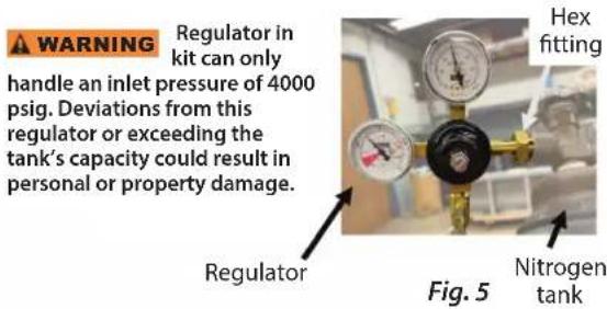
Any gas tank that provides an inlet pressure more than 4,000 PSI is
not recommended, otherwise there will be a reduced oxygen supply which can result in injury, death, and property damage to the regulator.

Any threaded connection has a risk of leakage if Teflon tape is not
applied resulting in a reduced oxygen supply which can lead to injury or death.

Any threaded connection needs to be properly affixed by a wrench
according to the installation instructions, otherwise there will be a reduced oxygen supply which can lead to injury or death.

When removing and replacing kegs, ensure the gas is properly
shut off by setting the regulator or gas tank to a closed position, otherwise there will be a reduced oxygen supply which can lead to injury or death.

Ensure safety chain is properly mounted to the refrigeration unit
per the installation instructions, otherwise property damage may occur to the nitrogen tank if toppled. Personal damage may ensue if the nitrogen tank leaks from being damaged resulting in injury or death.

When removing and replacing kegs, ensure they are properly
vented by pulling upwards on the ring for safety release valve for ten seconds, otherwise personal injury may occur when removing the its lid.

A refrigeration unit must not be drilled into unless the specified area
is safe to drill by a mounting template or no-drill-zone drawing, otherwise there may be electrical or refrigerant damage.

Ensure the keg lid rests flush and an even seal is produced, otherwise the
keg will not hold its pressure and the beverage will not dispense properly.

When removing or replacing kegs, avoid any unnecessary contact to
the air distributor and nitrogen infuser to avoid property damage.
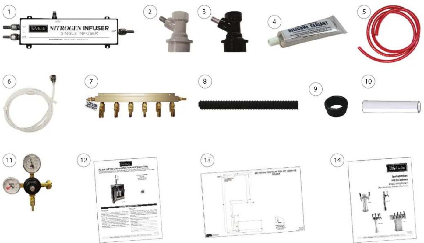
RS-NDK - PARTS LIST

ITEM NO. DESCRIPTION QTY.
| 1 Infuser, Single Nitrogen 1 EA | ||
| 2 Disconnect, Ball-Lock, For Gas (Gray) 4 EA | ||
| 3 Disconnect, Ball-Lock, For Liquid (Black) 4 EA | ||
| 4 Silicone 1 EA | ||
| 5 Red Gas Line 30 FT | ||
| 6 Beverage Tubing 5 EA | ||
| 7 Distributor, Air 6-Way 1 EA | ||
| 8 Tubing, Snorkel 5 FT | ||
| 9 Bushing 1 EA | ||
| 10 | Sleeve, Air | 1 EA |
| 11 | Regulator, Nitrogen Twin-Gauge | 1 EA |
| 12 | Air Scoop | 1 EA |
| 13 | Nitro Installation Instructions | 1 EA |
| 14 | Mounting Template, 1031011 | 1 EA |
| 15 | Dispensing Tower Installation Instructions | 1 EA |
| Page 7 | Bag, Tapping Parts | 1 EA |
Perlick is committed to continuous improvement. Therefore, we reserve the right to change specifications without prior notice
1030849 (SINGLE INFUSER) - PARTS LIST
ITEM NO. DESCRIPTION QTY.
| 1 Infuser, Single Nitrogen 1 EA | |
| 2 Disconnect, Ball-Lock, For Gas (Gray) 4 EA | |
| 3 Disconnect, Ball-Lock, For Liquid (Black) 4 EA | |
| 4 Silicone 1 EA | |
| 5 Red Gas Line 30 FT | |
| 6 Beverage Tubing 5 EA | |
| 7 Distributor, Air 6-Way 1 EA | |
| 8 Tubing, Snorkel 5 FT | |
| 9 Bushing 1 EA | |
| 10 Sleeve, Air | 1 EA |
| 11 Regulator, Nitrogen Twin-Gauge | 1 EA |
| 12 Nitro Installation Instructions | 1 EA |
| 13 Mounting Template, 1031011 | 1 EA |
| 14 Dispensing Tower Installation Instructions | 1 EA |
| Page 7 Bag, Tapping Parts | 1 EA |
Perlick is committed to continuous improvement. Therefore, we reserve the right to change specifications without prior notice
1030850 (DUAL INFUSER) - PARTS LIST
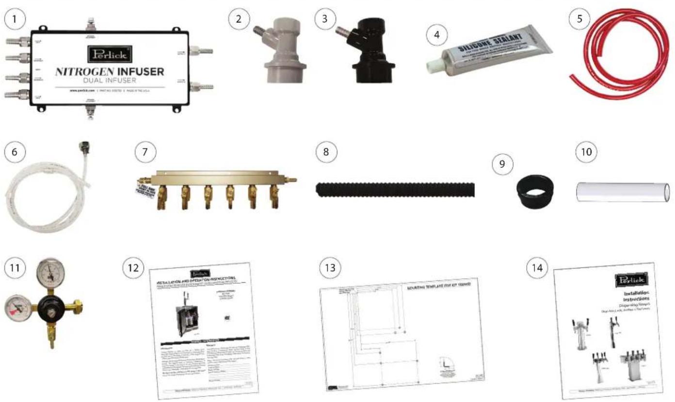
ITEM NO. DESCRIPTION QTY.
| 1 Infuser, Dual Nitrogen 1 EA | ||
| 2 Disconnect, Ball-Lock, For Gas (Gray) 4 EA | ||
| 3 Disconnect, Ball-Lock, For Liquid (Black) 4 EA | ||
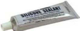
| 4 Silicone 1 EA | ||
| 5 Red Gas Line 30 FT | ||
| 6 Beverage Tubing 5 EA | ||
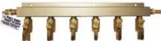
| 7 Distributor, Air 6-Way 1 EA | ||
| 8 Tubing, Snorkel 5 FT | ||
| 9 Bushing 1 EA | ||
| 10 | Sleeve, Air | 1 EA |
| 11 | Regulator, Nitrogen Twin-Gauge | 1 EA |
| 12 | Nitro Installation Instructions | 1 EA |
| 13 | Mounting Template, 1031023 | 1 EA |
| 14 | Dispensing Tower Installation Instructions | 1 EA |
| Page 7 | Bag, Tapping Parts | 1 EA |
Perlick is committed to continuous improvement. Therefore, we reserve the right to change specifications without prior notice
Perlick
PERLICK NITRO BEVERAGE DISPENSING KIT
Operation/Installation Manual
TAPPING PARTS BAG
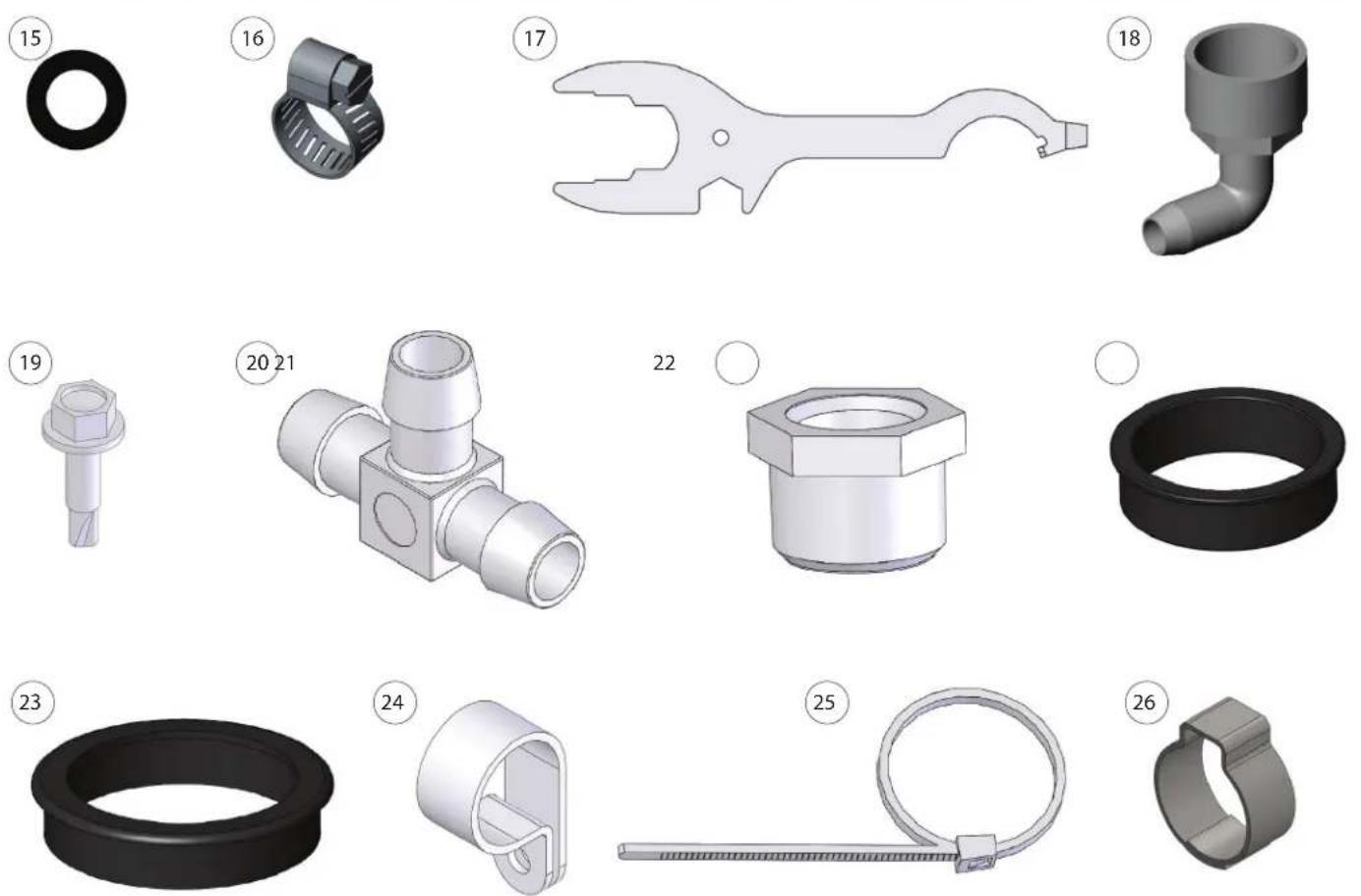
ITEM NO. DESCRIPTION QTY.
| 15 Gasket, Coupling 10 | |
| 16 Clamp, Stainless Steel, Worm-drive 19 | |
| 17 Wrench, Combination 1 | |
| 18 Elbow, Nylon, 3/4" FPT X 1/2" Hose Barb 1 | |
| 19 Screw, Self-Drilling, #10 X 3/4", Hex Washer Head with Serrations 8 | |
| 20 Tee, 1/2" Insert, Three Hose Barb 1 | |
| 21 Bushing, Reducer, Nylon, 3/4" NPT, 1/2" NPT 1 | |
| 22 Bushing, Snap, 1.5", Nylon | 4 |
| 23 Bushing, Snap, 2", Nylon | 2 |
| 24 Clamp, Cable, 3/4" Dia. X 1/2", Plastic | 3 |
| 25 Tie, Cable | 1 |
| 26 Clamp, Stepless Ear, Stainless Steel (Oetiker Clamp) | 19 |
Perlick is committed to continuous improvement. Therefore, we reserve the right to change specifications without prior notice
ASSEMBLY INSTRUCTIONS FOR SINGLE NITROGEN INFUSER KIT(1030849, RS-NDK)

flowchart
graph TD
    A["NITROGEN TANK"] --> B["COFFEE KEG"]
    B --> C["INPUTS"]
    C --> D["GAS BEVERAGE"]
    D --> E["OUTPUT"]
    E --> F["TO FAUCET"]
    G["REGULATOR"] --> H["INPUTS"]
    H --> C
    style A fill:#f9f,stroke:#333
    style B fill:#ccf,stroke:#333
    style C fill:#cfc,stroke:#333
    style D fill:#fcc,stroke:#333
    style E fill:#cff,stroke:#333
    style F fill:#ffc,stroke:#333

All Components shown are reference only
- Drill six mounting holes according to Operation 1 via an electric drill and a 5/32" drill bit.
- Determine how many nitrogen lines are needed for you application. Cut to length (leave room for error) and mount the gas lines to the air distributor with worm-drive clamp or Oetiker clamp (Reference Operation 2).
- Mount the 6-way air distributor by aligning its holes with the drilled holes in Operation 1. Install two self-tapping screws from the parts bag with a drill and 5/16" hex bit according to Operation 2.
- Install the nitrogen source inside or outside the refrigeration unit according to Operation 3.
- Connect a red gas line to the regulator (Fig. 5) and to the inlet of the 6-way air distributor (Fig. 4). Use a worm-drive clamp or Oetiker clamp (Reference Operation 3).
- Install the regulator to the nitrogen source using a large adjustable wrench and teflon tape for the threaded connection (Reference Operation 3). Ensure the tank and regulator are set to their closed positions (figure 17).
- Install one gas line from the 6-way air distributor and one new beverage line to the nitro infuser's inputs with a worm-drive clamp or Oetiker clamp and cut off threaded connector for the beverage line according to Operation 4.
- Install one beverage line to the output beverage connection on the infuser via a worm-drive clamp or Oetiker clamp (Reference Operation 4).
- Mount the nitrogen infuser to holes drilled in Step 1 above using the small black screws from the infuser and a phillips bit and drill.
-
Attach the beverage line from the input of nitro infuser to a black quick disconnect with a worm-drive or Oetiker clamp (Reference Operation 5).
-
Repeat Step 8 but attach a red gas line from the air distributor to the gray quick disconnect with a worm-drive clamp or Oetiker clamp (Reference Operation 5).
- Connect the quick disconnects to the keg(s) by lifting up on the outer ring (Reference Operation 6).
a) Black quick disconnect attaches to out.
b) Gray quick disconnect attaches to in. - Connect the output beverage line from the infuser (and any other beverage lines) to the tower (Operation 7). Cut off connectors if the tower has a hose barb, and not a threaded connection.
- Mount the faucets to the tower and the tower to refrigeration cabinet (Reference Operation 8).
- Install the air scoop according to Operation 9.
- If a nitrogen tank is being used inside the refrigeration unit, connect both ends of the safety chain and wrap the chain around the tank. Drive a self-taping screw through the chain.
- Ensure that the tank, regulator and all non-used gas lines are set to a closed position (Fig. 18).
- Using the adjustable screw on the front of the regulator, adjust the pressure to 28 PSI for optimal dispensing.
- Adjust the NCS dial on the infuser to the desirable output for coffee and froth.
- Open the gas tank and set the regulator to an open position.
- Allow the beverage 1-2 minutes to pressurize and serve!
ASSEMBLY INSTRUCTIONS FOR DUAL NITROGEN INFUSER KIT(1030850, RS-NDK)

flowchart
graph TD
    A["TO FAUCET"] --> B["OUTPUTS"]
    C["TO FAUCET"] --> B
    B --> D["INPUTS"]
    D --> E["NCS"]
    E --> F["GAS A"]
    E --> G["BEVERAGE A"]
    E --> H["BEVERAGE B"]
    E --> I["GAS B"]
    J["NITROGEN TANK"] --> K["REGULATOR"]
    L["COFFEE KEG"] --> K
    M["COFFEE KEG"] --> K
    K --> N["NCS"]
    N --> O["Output"]
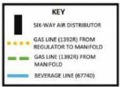
Fig.16 (Line Setup Check for Dual Infuser)
All Components shown are reference only
- Drill six mounting holes according to Operation 1 via an electric drill and a 5/32" drill bit.
- Determine how many nitrogen lines are needed for you application. Cut to length (leave room for error) and mount the gas lines to the air distributor with worm-drive clamp or Oetiker clamp (Reference Operation 2).
- Mount the 6-way air distributor by aligning its holes with the drilled holes in Step 1 above. Install two self-tapping screws from the parts bag with a drill and 5/16" hex bit according to Step 2.
- Install the nitrogen source inside or outside the refrigeration unit according to Operation 3.
- Connect a red gas line to the regulator (Fig. 5) and to the inlet of the 6-way air distributor (Fig. 4). Use a worm-drive clamp or Oetiker clamp (Reference Operation 3).
- Install the regulator to the nitrogen source using a large adjustable wrench and teflon tape for the threaded connection (Reference Operation 3). Ensure the tank and regulator are set to their closed positions (figure 17).
- Install two gas lines from the 6-way air distributor and two new beverage lines to the nitro infuser's inputs with a worm-drive clamp or Oetiker clamp and cut off threaded connector for the beverage line according to Operation 4.
- Install two beverage lines to the output beverage connection on the infuser via a worm-drive clamp or Oetiker clamp. (Reference Operation 4)
- Mount the nitrogen infuser to holes drilled in Step 1 using the small black screws from the infuser and a phillips bit and drill.
-
Attach the two beverage lines from the input of nitro infuser to a black quick disconnect with a worm-drive or Oetiker clamp (Reference Operation 5).
-
Repeat Step 8, but attach two gas lines from the air distributor to the gray quick disconnect with a worm-drive clamp or Oetiker clamp (Reference Operation 5)
- Connect the quick disconnects to the keg(s) by lifting up on the outer ring (Reference Operation 6).
a) Black quick disconnect attaches to out.
b) Gray quick disconnect attaches to in. - Connect the two output beverage lines from the infuser (and any other beverage lines) to the tower Operation 7. Cut off connectors if the tower has a hose barb, and not a threaded connection.
- Mount the faucets to the tower and the tower to refrigeration cabinet (Reference Operation 8).
- Install the air scoop according to Operation 9.
- If a nitrogen tank is being used inside the refrigeration unit, connect both ends of the safety chain and wrap the chain around the tank. Drive a self-taping screw through the chain.
- Ensure that the tank, regulator and all non-used gas lines are set to a closed position. (Fig. 18)
- Using the adjustable screw on the front of the regulator, adjust the pressure to 28 PSI for optimal dispensing.
- Adjust the NCS dial on the infuser to the desirable output for coffee and froth.
- Open the gas tank and set the regulator to an open position.
- Allow the beverage 1-2 minutes to pressurize and serve!
OPERATION #1 - MOUNTING LOCATIONS FOR SINGLE INFUSER
-
Mark holes according to the drill sites below with a hammer and center punch. Place the mounting template in the corner of the refrigeration unit according to the direction below. The mounting template (1031011) can be found in the kit and on perlick.com.
-
Drill the six mounting holes shown on this page with a 5/32" drill bit.
NOTICE
Any deviation from this pattern more than a 1/2" from it's original location can result
in electrical or refrigerant damage.
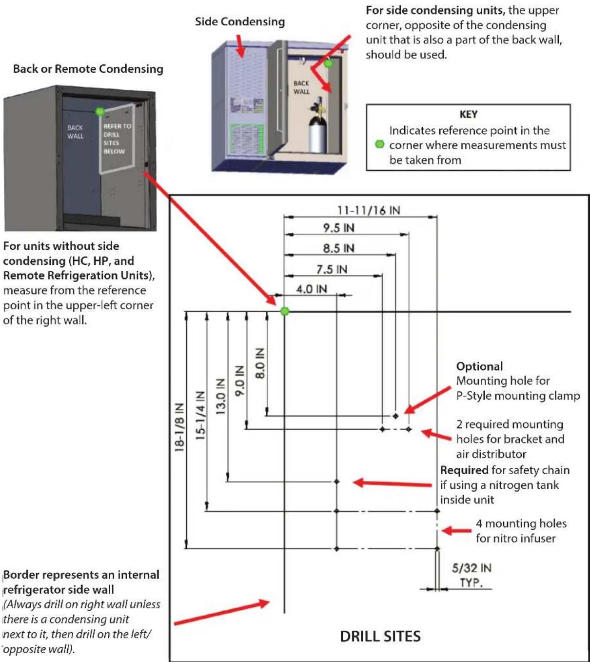
For units without side condensing (HC, HP, and Remote Refrigeration Units), measure from the reference point in the upper-left corner of the right wall.
For side condensing units, the upper corner, opposite of the condensing unit that is also a part of the back wall, should be used.
KEY
Indicates reference point in the
corner where measurements must be taken from
(Always drill on right wall unless there is a condensing unit next to it, then drill on the left/ opposite wall).
Perlick is committed to continuous improvement. Therefore, we reserve the right to change specifications without prior notice
Perlick
OPERATION #1 - MOUNTING LOCATIONS FOR DUAL INFUSER
-
Mark holes according to the drill sites below with a hammer and center punch. Place the mounting template in the corner of the refrigeration unit according to the direction below. The mounting template (1031023) can be found in the kit and on perlick.com.
-
Drill the six mounting holes shown on this page with a 5/32" drill bit.
NOTICE
Any deviation from this pattern more than a 1/2" from it's original location can result
in electrical or refrigerant damage.
Back or Remote Condensing

For units without side condensing (HC, HP, and Remote Refrigeration Units), measure from the reference point in the upper-left corner of the right wall.
Side Condensing

For side condensing units, the upper corner, opposite of the condensing unit that is also a part of the back wall, should be used.
KEY
Indicates reference point in the corner where measurements must be taken from
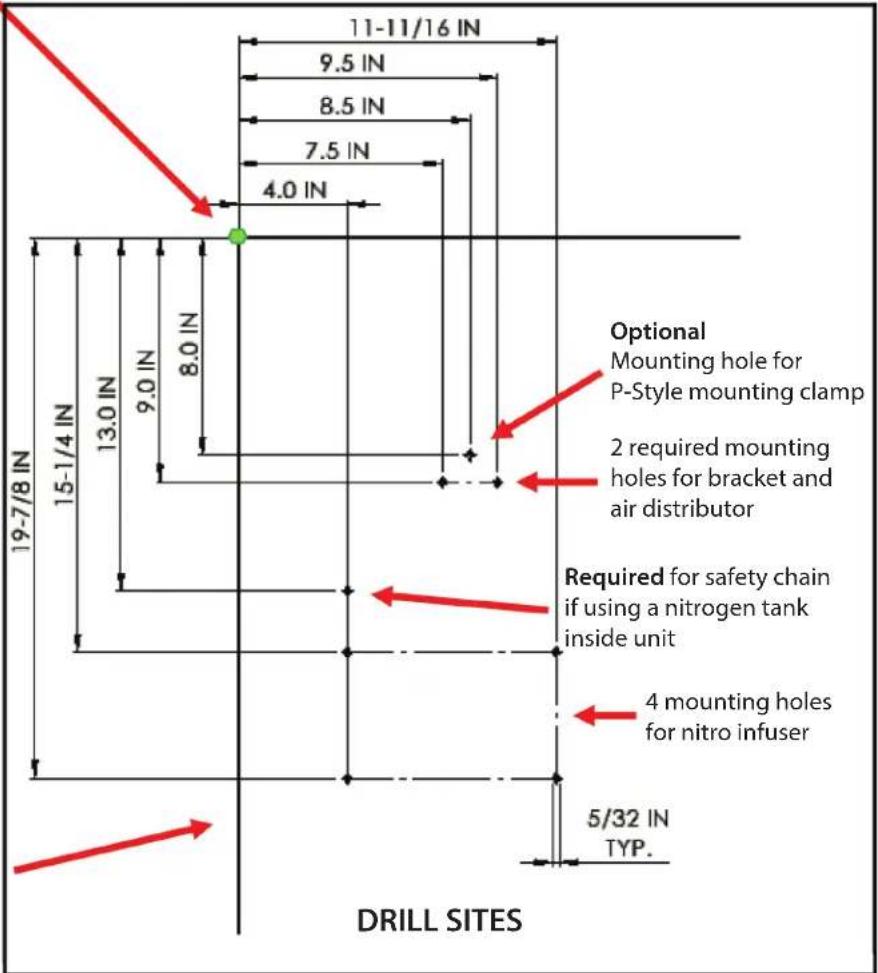
Border represents an internal refrigerator side wall
(Always drill on right wall unless there is a condensing unit next to it, then drill on the left/opposite wall).
Perlick is committed to continuous improvement. Therefore, we reserve the right to change specifications without prior notice
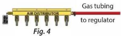
OPERATION #2-AIR DISTRIBUTOR INSTALLATION
- Determine how many gas lines are needed
a) Two nitrogen lines are needed for nitro-brew coffee.
b) One nitrogen line is needed for cold brew. -
Attach the required amount of red gas tubing to the air distributor for the application. Compress a worm-drive clamp or Oetiker clamp onto each gas tube. Ensure the tubing is being compressed to the hose barb.
a) Ensure worm-drive clamp or Oetiker clamp doesn't interfere with opening/closing valve (Fig. 1). -
Drive two self-taping screws with a 5/16" hex bit from the tapping parts bag provided in the kit to attach the air distributor to the cabinet.

natural_image
Mechanical assembly diagram showing a red cylindrical component with a yellow bracket and a gray handle, labeled as Fig. 1 (no text or symbols on the diagram itself)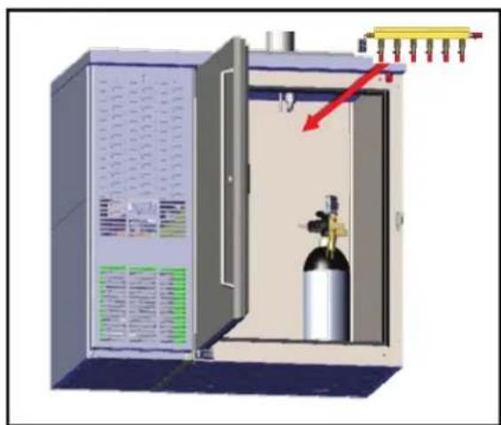
natural_image
3D diagram of a gas cylinder inside a control cabinet with a red arrow pointing to the cylinder (no text or symbols present)Fig. 2
Ensure worm-drive clamp or Oetiker clamp clamp does not interfere with opening and closing of valve.

Fig. 3
OPERATION #3 - NITROGEN TANK INSTALLATION
INTERNAL NITROGEN TANK MOUNTING
- Place the tank, regulator, and air distributor inside the refrigeration unit (Fig. 4) to determine length of gas tubing in Step 2.
- Cut the red gas tubing to the desired length based on where the components will be located.
- Route the red gas tubing to the regulator (Fig. 5) and to the air distributor (Fig. 4). Attach the tubing to the hose barb with a worm-drive clamp or Oetiker clamp. Ensure it is compressing the tube and hose barb.
- Attach the regulator to nitrogen tank via an adjustable wrench. Rotate the hex fitting (Fig. 5) until the it can no longer be rotated.
a) Make sure to use teflon tape on all pressurized, threaded connections.
EXTERNAL NITROGEN TANK MOUNTING
- For an external nitrogen source, identify the knockout's location and remove it.
- Cut the red gas tubing to the desired length based off of where the external nitrogen tank is located.
- Place the air distributor inside the refrigeration unit and route the red gas tubing through the knockout hole.
- Attach the routed red gas tubing to the air distributor (Fig. 1) and regulator (Fig. 5) to barbed fittings and secure the tubing in place with worm-drive clamp or Oetiker clamp (Reference Fig. 5 to observe installed components).
- Ensure the knockout hole is sealed (with the provided sealant).
- Attach regulator to nitrogen tank via an adjustable wrench. Rotate the hex fitting (Fig. 5) until the it can no longer be rotated.
a) Make sure to use teflon tape on all pressurized, threaded connections.

All Components shown are reference only

OPERATION #4 - NITROGEN INFUSER INSTALLATION
- Attach a new beverage line and a red gas line from the air distributor to the input hose barbs on the nitrogen infuser. The inputs will say gas & beverage. (Fig. 9)
a) If the dual infuser is being used, repeat
Step 1 for the other two inputs.
b) Place a worm-drive clamp or Oetiker clamp around the tubing before connecting to the hose barb.
c) Ensure to never have a smaller bend radius than 2 inches during installation.
d) Remove the connector on the beverage lines connected to the input.
- Repeat Step 1, however attach new beverage lines to output(s). One output for single and two for dual. These lines will later be connected to the tower (Fig. 8).
a) If the tower does not have a threaded connection, remove the connector.
WARNING
Never apply more than a two-inch bend radius to beverage tubing.
- Attach the infuser to the cabinet via a phillips screwdriver and the four black screws provided in the nitrogen infuser's packaging to the mounting holes drilled in Operation 1.
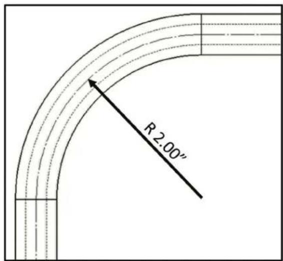
Fig. 8
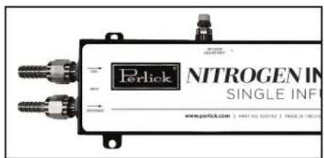
Single infuser inputs

Dual infuser inputs
- Place worm-drive or Oetiker clamps around tubing that will attach to the quick disconnects.
-
Use the beverage tubing from the nitrogen infuser's inputs (one line for single infuser and two lines for the dual infuser) in Operation 4 and attach it to the hose barb on the black quick disconnect(s) (Fig. 10).
-
Slide the worm-drive clamp or Oetiker clamp over the hose barb and tubing and tighten the clamp with a 1/4" nut driver to compress the beverage line to the hose barb.
- Repeat Steps 1 through 3 for the red gas lines from the air distributor but ensure the gas line is connected to the gray quick disconnect. There must be one gas line per beverage input line from the nitro infuser (Fig. 11).
Black quick
disconnect
for liquid
natural_image
Close-up of a gas cylinder with black and white components, no visible text or symbolsFig. 10 Fig. 11
natural_image
Close-up of a white industrial robotic arm with a handle and base, no visible text or symbolsGray quick disconnect for gas
OPERATION #6 - CONNECTING TO KEG
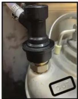
- Place quick disconnects onto tank (Fig. 11).
a) It is critical that the gray or gas quick disconnect(s) are placed where the tank has the word in embossed into its surface (Fig. 11 and 12).
b) It is critical that the black or liquid quick disconnect(s) is placed where the tank has out embossed into its surface (Fig. 10 and 12). - Make sure a good connection is made and the connectors are seated properly.
a) Pull up on the plastic ring to unlock the quick disconnect. This will allow the quick disconnect to be easily secured or removed.
b) A noticeable clicking sound & positional shift will be made when the disconnect is secured.
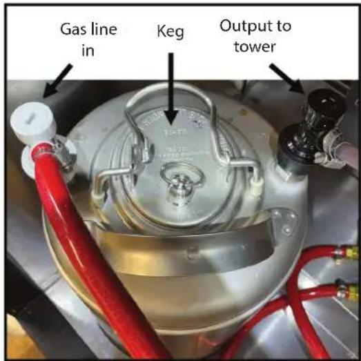
Fig. 12
- If the connection point sticking out from the tower is threaded, simply screw on the beverage lines. Otherwise, follow Steps 2-6.
- Cut off threaded connector from beverage tubing.
- Place a worm-drive or Oetiker clamp, from the tapping parts bag, around the beverage tubing that comes from the output of the nitrogen infuser.
- Connect the tubing to the hose barb sticking out from the tower's base.
- Position and tighten the worm-drive or Oetiker clamp(s) to compress beverage lines onto the hose barb (Fig. 13).
- Ensure the newly installed beverage lines are properly routed through the refrigeration unit before mounting the tower.

Fig. 13
- Install the tower and drainer or drip pans per dispensing tower installation instructions (included with this kit and may also be found at perlick.com)
a) Ensure the appropriate type/model/design. Refer to the Tower Installation Manual.
NOTICE
The Sexy/Adara Towers' installation mirror's the Lucky and Panther Towers'
installation instructions.
- Attach the faucets to the tower via the faucet wrench located in the tapping parts bag.

natural_image
Two 3D diagrams showing a door opening with a red arrow indicating force or movement, no text or symbols present.Fig. 14
Perlick is committed to continuous improvement. Therefore, we reserve the right to change specifications without prior notice
- Refer to the Tower Installation Manual in Operation 8 for additional material on air scoop installation.
- Identify the air scoop and how many attachment points are needed (varies based on refrigeration model).
- Find the evaporator fan's cover in the refrigeration unit and remove the necessary screws via a philips screwdriver for the air scoop's attachment points.
-
Replace the screws on the evaporator fan's cover with the air scoop installed.
-
Place the accordian-style (black) tubing into the bushing.
a) Place a zip tie on the side of the tubing nearest to the evaporator fan. This will ensure the tubing does not slip out. - Snap in bushing with the tubing and zip tie installed.
- Gauge how much tubing needs to be routed into the tower and cut.
a) Ensure there is at least a couple inches of tubing routed up into the tower for sufficient air flow.
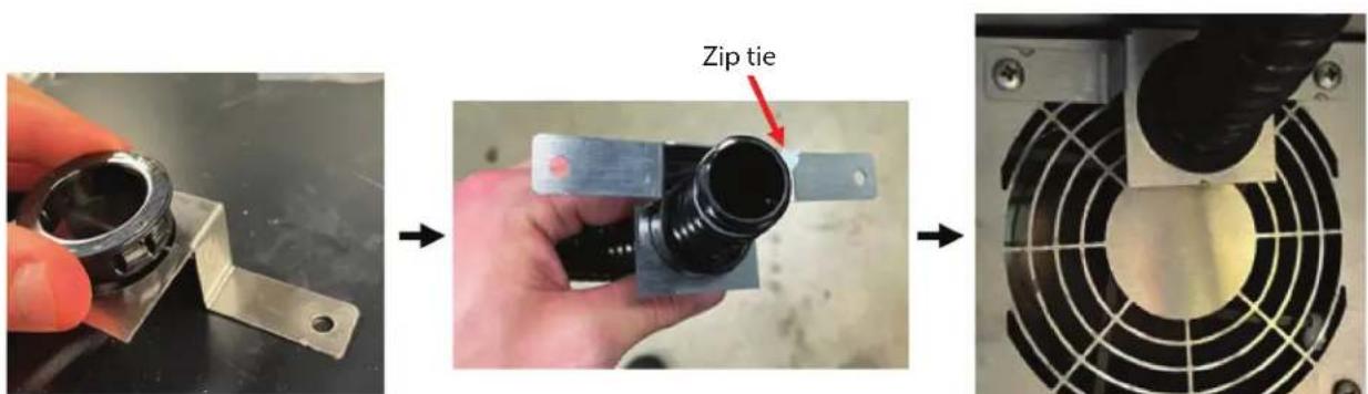
Fig. 15
Installation Process for air scoop, tubing, and bushing

Perlick is committed to continuous improvement. Therefore, we reserve the right to change specifications without prior notice
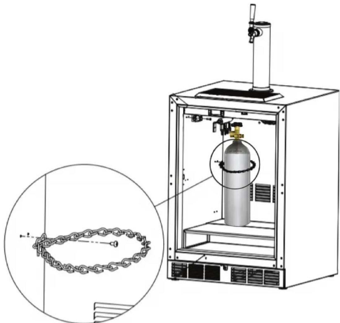
OPERATION #10- SECURING NITROGEN KEG TO REFRIGERATION UNIT
- Locate the mounting hole in Operation 1 designated for the safety chain.
- Connect both ends of the safety chain together and with pliers, close the open loop (Fig. 17).
- Drive a self-tapping screw from the parts bag through the S-hook (Fig. 17).
- Give the chain a slight tug to ensure it is properly affixed.
- Install nitrogen tank by sliding safety chain up the tank until it is secure.
natural_image
Technical illustration of a gas cylinder inside a mechanical device, with an inset showing a chain and chain ring (no text or symbols present)Fig. 17
FILLING KEG WITH NITRO BREW
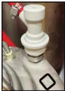
- Before opening the keg, ensure the system is depressurized.
a) Close all valves on the nitrogen tank & air distributor(s). Refer to Fig. 18 if unsure on what a closed/open valve looks like.
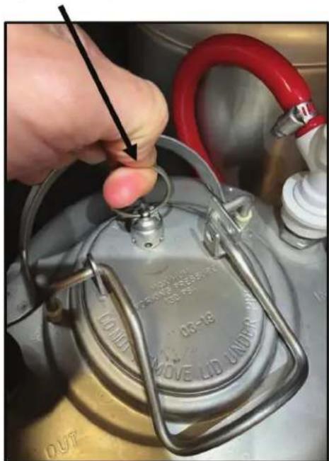
b) Pull upwards on the pressure relief on the keg for 10 seconds (Fig. 19).
-
Open the keg cover and remove lid from keg.
-
Place the funnel into the top of the keg, then place strainer into funnel.
a) The strainer will improve the integrity of the system by disallowing coffee grounds to build up.
-
Make sure the keg, funnel, and stainer are clean prior to use.
-
Slowly pour coffee into the stainer.
-
Clean the strainer as needed so that clogging is kept to a minimum. Repeat these steps with as many tanks as desired.
-
After the beverage is in the keg and the cover is replaced, move tank into position and using Operation 6, attach lines.

Fig. 18
Pull ring to alleviate pressure.
natural_image
Close-up of a hand adjusting a metal tank lid with red hose and metallic casing (no visible text or symbols)Fig. 19
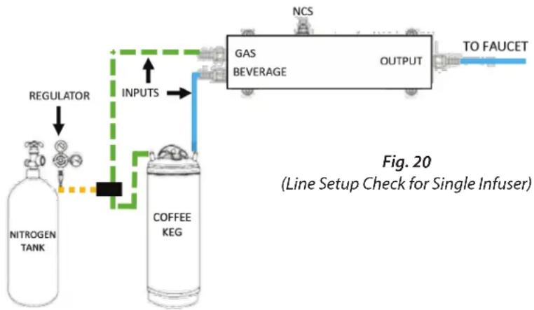
LINE SETUP CHECK SINGLE INFUSER (FOR POST-INSTALLATION & CLEANING)
- Ensure there is a nitrogen line connected to the input of the nitrogen infuser and the air distributor.
- Make sure the beverage tubing is connected to the input of the nitrogen infuser and attached to a BLACK quick disconnect.
- Check that there is a gray quick disconnect attached to a air distributor line.
- See if quick disconnects are properly placed on the tank according to Operation 7.
-
Confirm the connection is made from the regulator to the air distributor.
a) If two air distributors are used, check the connections to the barbed tee fitting, air distributors, and regulator. -
Ensure the regulator is tightly affixed to the tank.
- Tug each line installed to ensure a secure connection is made between the hose barb and the line.
a) If the line makes any indication that its slipping out of the worm-drive clamp or Oetiker clamp, uninstall the clamp and redo this connection. - Before opening regulator and setting pressure, fill kegs with desired beverage.
- Set the regulator to 28 PSI.
- Wait 1-2 minutes for the system to pressurize.
- The system is ready dispense!
flowchart
graph TD
    A["NITROGEN TANK"] --> B["Regulator"]
    B --> C["COFFEE KEG"]
    C --> D["INPUTS"]
    D --> E["GAS BEVERAGE"]
    E --> F["OUTPUT"]
    F --> G["TO FAUCET"]
    style A fill:#f9f,stroke:#333
    style B fill:#ccf,stroke:#333
    style C fill:#cfc,stroke:#333
    style D fill:#fcc,stroke:#333
    style E fill:#cff,stroke:#333
    style F fill:#ffc,stroke:#333
    style G fill:#cfc,stroke:#333
All Components shown are reference only
LINE SETUP CHECK DUAL INFUSER (FOR POST-INSTALLATION & CLEANING)
- Ensure there are two nitrogen lines connected to the inputs of the nitrogen infuser and an air distributor.
- Make sure two beverage tubes are connected to the input of the nitrogen infuser (Beverage A & B) and are attached to a black quick disconnect.
- Check that there are two gray quick disconnects attached to two different lines on the air distributor.
- See if quick disconnects are in properly installed on the tank according to Operation 7.
- Check the connections between the barbed tee fitting, air distributors, and regulator (Fig. 21).
-
Ensure the regulator is tightly affixed to the tank.
-
Tug each and beverage tube installed in this operation to ensure a secure connection is made.
a) If the line makes any indication that its slipping out of the worm-drive clamp or Oetiker clamp, uninstall the clamp and redo this connection. - Before opening regulator and setting pressure, fill kegs with desired beverage.
- Set the regulator to 28 PSI.
- Wait 1-2 minutes for the system to pressurize.
- The system is ready to dispense.

flowchart
graph TD
    A["TO FAUCET"] --> B["OUTPUTS"]
    C["TO FAUCET"] --> B
    B --> D["INPUTS"]
    D --> E["NCS"]
    E --> F["COFFEE KEG"]
    E --> G["NITROGEN TANK"]
    H["GAS A"] --> I["BEVERAGE A"]
    J["GAS B"] --> K["BEVERAGE B"]
    L["NCS"] --> M["REGULATOR"]
    M --> N["NITROGEN TANK"]
    style M fill:#f9f,stroke:#333
Fig. 21 (Line Setup Check for Dual Infuser)
All Components shown are reference only
SYSTEM CLEANING OVERVIEW
Regardless of what type of cleaning chemical you are using, you should follow three simple steps when cleaning your nitro beverage dispensing system.
- You need to start by flushing any remaining coffee within your beverage lines. Do this by pushing clean water through your lines and opening the faucet on the service side. At first, you will see a mixture of coffee and water flowing through the faucet. Continue to run the faucet until the water runs clear.
Removing coffee from the lines will ensure the chemicals will be able to contact the surface of your lines and clean the residue that remains.
- Next, you want to introduce the chemicals to the line. Using pressurized cleaning, you need to keep the faucets closed and allow the chemicals to remain in the lines while pressurized for 15 minutes.
CAUTION
Before using any cleaning chemicals, food products and
packaging materials must be removed from the room or carefully protected.
CAUTION
Always use proper protective wear including gloves and eye
protection.
CAUTION
Use only cleaning chemicals that are designed for cold
beverage equipment and dispensing systems that rinse clean and do not leave behind any residue or odor.
NOTICE
When adding the chemicals, you need to strictly adhere to
the concentration recommendations as stated by the chemicals' manufacturer. Failure to do so could either make the concentration dangerously high—risking damage to both you and your system—or it could make the solution too diluted, thus making it ineffective.
Further, most manufacturers have a recommended solution temperature. Follow these instructions as well, as certain chemical solutions may be less effective at certain temperatures.
-
Finally, you want to flush the lines with water again, this time to remove the chemical solution. Because cleaning chemicals may not look much different than water, we recommend using a pH tester to ensure no chemicals remain. Regardless of what chemical you are using, the water flowing out of the faucet should return to a neutral pH before reusing the system.
-
Once you have cleared out the cleaning solution, reattach your keg lines and run beverage through the faucets until any remaining water has been eliminated.
STEP BY STEP CLEANING INSTRUCTIONS
FLUSH KEGS OF REMAINING BEVERAGE
- Empty kegs of all product.
- Turn Nitrogen Gas off and vent keg pressure.
- Remove stout faucet nozzles and soak in carbonated water. Clean nozzles with brush.
- Close Faucets.
CHEMICALLY CLEAN SYSTEM
- Remove keg lid.
- Pour a specialized cleaning agent designed for cold coffee dispensing systems into rinsed empty keg.
NOTICE
Strictly adhere to the concentration
recommendations as stated by the chemicals' manufacturer. Failure to do so could either make the concentration dangerously high —risking damage to both you and your system — or it could make the solution too diluted, thus making it ineffective.
-
Reattach keg lid. Pressurize with Nitrogen.
-
Place an empty bucket under the faucet.
-
Flush out product from all beverage lines until all you see is cleaning solution.
-
Close the faucet and allow lines to soak for 15 minutes.
-
Open faucets and empty until cleaning solution is completely flushed from lines.
-
Close faucets.
-
Turn Nitrogen Gas off and vent keg pressure.
-
Remove keg lid and rinse keg thoroughly with fresh water.
FLUSH SYSTEM WITH RINSE WATER
- Fill tank with a minimum of 2 gallons of warm (80° - 95°F) rinse water.
- Reattach Keg lid and pressurize with Nitrogen.
- Place an empty bucket under the faucet.
- Open faucets and thoroughly flush cleaner from all beverage lines with rinse water.
- Check rinse water with PH paper to ensure all cleaning solution is rinsed from lines.
- If rinse water does not test PH neutral, continue rinsing and retest until PH neutral is obtained.
- Replace nozzle on stout faucets.
- Recouple your coffee keg and pressurize with Nitrogen.
- Flush out remaining water in system from both beverage lines until a minimum of 12 ounces of coffee is flushed through the lines and discard.
- Close faucets.
DAILY MAINTENANCE
- Remove stout faucet nozzles and soak in carbonated water.
- Clean nozzles with brush.
TROUBLESHOOTING GUIDE
| ISSUE PROBABLE CAUSE REMEDY | ||
| Why is my cold brew running slower than usual? | Clogged Stout Faucet | If your cold brew is running slowly, unscrew the spout and soak it in warm water with your cleaner of choice. Another tip is to soak the stout nozzle in carbonated water. The rising bubbles should help loosen anything that may be clogging it. To ensure the stout nozzle is clean, shine a flashlight (your phone is great for this) through the bottom of the nozzle and monitor if any openings are clogged. |
| Nitrogen Gas System | Double check your gas tank is full and wide open. Assure there are no leaks in the gas line by spraying connections with soapy water and looking for bubbles. Double check lines for kinks. If you are using a Corny Keg, check the lid seal and bar lock connectors for leaks as well. | |
| Beverage Line is Frozen | You can thaw these lines by leaving your refrigerator door open for a few minutes, or by grabbing the frozen line with your bare hands until the liquid starts flowing at a normal rate again. Use a commercial grade thermometer to double check your system is running to expectations. | |
| Why is my beverage sputtering? | Infusion Level Too High | Adjust infusion level by turning your Nitrogen Control System (NCS) valve to a closed position. Open NCS valve to add nitrogen as desired. You can lock your infusion level by tightening the hex nut against the NCS. If the NCS valve will not turn, ensure the hex nut is loose and not already locked against the body. Refer to the Nitrogen Adjustment Video on the first page of the installation instructions. |
| Nitrogen Gas Pressure is Too High | We recommend setting your nitrogen regulator between 28-32 PSI as a starting point. If you find the beverage is not flowing as expected, adjust as necessary. | |
| Clogged Stout Faucet | If your cold brew is running slowly, unscrew the spout and soak it in warm water with your cleaner of choice. Another tip is to soak the stout nozzle in carbonated water. The rising bubbles should help loosen anything that may be clogging it. To ensure the stout nozzle is clean, shine a flashlight (your phone is great for this) through the bottom of the nozzle and monitor if any openings are clogged. | |
| Beverage Line is Frozen | You can thaw these lines by leaving your refrigerator door open for a few minutes, or by grabbing the frozen line with your bare hands until the liquid starts flowing at a normal rate again. Use a commercial grade thermometer to double check your system is running to expectations. | |
| The infusion level is too little or too much | Nitrogen Gas System | Double check your gas tank is full and wide open. Assure there are no leaks in the gas line by spraying connections with soapy water and looking for bubbles. Double check lines for kinks. If you are using a Corny Keg, check the lid seal and bar lock connectors for leaks as well. |
| Nitrogen Control System (NCS) Valve | Begin with the NCS valve all the way closed. Open the valve to add nitrogen as desired. You can lock your infusion level by tightening the hex nut against the body. If the NCS valve will not turn, ensure the hex nut is loose and not already locked against the body. Refer to the Nitrogen Adjustment Video on the first page of the installation instructions. | |
| Issues with installation | N/A | Refer to the troubleshooting installation guide (Operation 16). |
Perlick is committed to continuous improvement. Therefore, we reserve the right to change specifications without prior notice
TROUBLESHOOTING INSTALLATION & CUSTOMER SERVICE INFORMATION
Is your beverage not dispensing?
a) Before ordering a service components (found at the end of this guide) for a nitro system, please check bullet points "b)" - "k)" and confirm your lines are properly setup according to Operation 12.
b) Check if beverage kegs are empty.
c) Ensure the beverage keg's lid is properly shut. The lid should be parallel to the ground if installed properly (should not be angled).
d) Check the regulator to see if the nitrogen tank is empty.
e) Ensure nitrogen tank and all necessary gas lines are set to an open position. Unused, open gas lines will cause the beverage to dispense improperly and cause a safety hazard since nitrogen is being released.
f) Tug each beverage and gas line by its connection to ensure a secure connection.
- If the tubing is sliding off the hose barb during the check, cut the tubing and reapply it to the hose barb. Ensure a hose drive clamp is firmly affixed and compressing the tubing to the barb.
g) Remove and reapply the quick disconnects to ensure they are properly attached.
h) Using an adjustable wrench, ensure the hex nut that attaches the regulator to the tank is firmly attached.
i) Ensure there are no beverage leaks by checking inside the refrigeration unit. Also, listen for any hissing or high-pitched noises to confirm there are no gas leaks.
j) Check to see if fluid is flowing in and out of the nitrogen infuser.
- If fluid flow can not be resolved through this troubleshooting process, proceed to the last step.
k) Reach out to customer support at techservice@partstown.com or 844-411-8050 for any additional questions.
SERVICE PARTS
 10309691 10309691 | 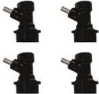 10309742 10309742 | 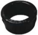 Includes Contents on page 710309753 Includes Contents on page 710309753 |
 4 4 |  10309775 10309775 |  1309786 1309786 |
 10309797 10309797 |  10309808 10309808 |  10309819 10309819 |
 103098210 103098210 | 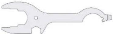 103098211 103098211 |  |
ITEM DESCRIPTION PART#
| 1 Grey Quick Disconnects For Gas Lines (4 ea.) 1030969 | |
| 2 Black Quick Disconnects For Beverage Lines (4 ea.) 1030974 | |
| 3 Parts Bag Plus Air Scoop Bushing (1 ea.) 1030975 | |
| 4 Silicone (1 ea.) 1030976 | |
| 5 Red Gas Tubing (30 ft.) 1030977 | |
| 6 Beverage Tube With Connector (5 ea.) 1030978 | |
| 7 6-Way Air Distributor (1 ea.) 1030979 | |
| 8 5 Feet Of Snorkel Tubing (5 ea.) 1030980 | |
| 9 Air Sleeve (1 ea.) 1030981 | |
| 10 Regulator (1 ea.) 1030982 | |
| 11 Wrench, Combination (1 ea.) | 1030986 |
Perlick is committed to continuous improvement. Therefore, we reserve the right to change specifications without prior notice
Scan the QR code
to watch our Nitro
Dispensing Kit Installation
video on YouTube


Form No. Z2751
Rev. 10.25.22
- INSTALLATION AND OPERATION INSTRUCTIONS
- PERLICK NITRO BEVERAGE DISPENSING KIT (SINGLE AND DUAL INFUSERS)
- PRODUCT NUMBERS
- GENERAL INFORMATION
- Introduction
- Warranty
- TABLE OF CONTENTS
- SAFETY
- IMPORTANT!
- WARNING: California Prop 65 Notice
- ADDITIONAL INFUSER WARRANTY INFORMATION
- NITROGEN INFUSER WARRANTY:
- NITRO INFUSER REPLACEMENT PARTS WARRANTY:
- Preparing For Use
- UNCRATING AND INSPECTION
- RS-NDK - PARTS LIST
- Perlick
- PERLICK NITRO BEVERAGE DISPENSING KIT
- Operation/Installation Manual
- ASSEMBLY INSTRUCTIONS FOR SINGLE NITROGEN INFUSER KIT(1030849, RS-NDK)
- ASSEMBLY INSTRUCTIONS FOR DUAL NITROGEN INFUSER KIT(1030850, RS-NDK)
- OPERATION #1 - MOUNTING LOCATIONS FOR SINGLE INFUSER
- NOTICE
- KEY
- OPERATION #1 - MOUNTING LOCATIONS FOR DUAL INFUSER
- Border represents an internal refrigerator side wall
- OPERATION #2-AIR DISTRIBUTOR INSTALLATION
- OPERATION #3 - NITROGEN TANK INSTALLATION
- INTERNAL NITROGEN TANK MOUNTING
- EXTERNAL NITROGEN TANK MOUNTING
- OPERATION #4 - NITROGEN INFUSER INSTALLATION
- WARNING
- OPERATION #6 - CONNECTING TO KEG
- OPERATION #10- SECURING NITROGEN KEG TO REFRIGERATION UNIT
- FILLING KEG WITH NITRO BREW
- LINE SETUP CHECK SINGLE INFUSER (FOR POST-INSTALLATION & CLEANING)
- LINE SETUP CHECK DUAL INFUSER (FOR POST-INSTALLATION & CLEANING)
- SYSTEM CLEANING OVERVIEW
- CAUTION
- STEP BY STEP CLEANING INSTRUCTIONS
- FLUSH KEGS OF REMAINING BEVERAGE
- CHEMICALLY CLEAN SYSTEM
- Strictly adhere to the concentration
- FLUSH SYSTEM WITH RINSE WATER
- DAILY MAINTENANCE
- TROUBLESHOOTING INSTALLATION & CUSTOMER SERVICE INFORMATION
- Is your beverage not dispensing?
Brand : Perlick
Model : 1030850
Category : Beer Tap