IGS-1000-8UP4X - Switch Planet - Free user manual and instructions
Find the device manual for free IGS-1000-8UP4X Planet in PDF.

User questions about IGS-1000-8UP4X Planet
0 question about this device. Answer the ones you know or ask your own.
Ask a new question about this device
Download the instructions for your Switch in PDF format for free! Find your manual IGS-1000-8UP4X - Planet and take your electronic device back in hand. On this page are published all the documents necessary for the use of your device. IGS-1000-8UP4X by Planet.
USER MANUAL IGS-1000-8UP4X Planet
Industrial Ethernet Switch
IGS-1000 Series
User's Manual
Table of Contents
- Package Contents .... 3
- Hardware Introduction .... 5
2.1 Switch Front Panel 5
2.2 LED Indicators....6
2.3 Switch Upper Panel 9
2.4 Wiring the Power Inputs....10
2.5 Wiring the Fault Alarm Contact 12
2.6 Grounding the Device....13
- Installation....14
3.1 DIN-rail Mounting Installation.... 14
3.2 Wall-mount Plate Mounting 16
- Product Specifications .... 17
- Customer Support 21
1. Package Contents
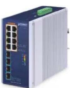
Thank you for purchasing PLANET IGS-1000-8T4X, IGS-1000-8UP4X and IGS-1000-4UP2X Industrial Ethernet Switches. The descriptions of this IGS-1000 series are as follows:
| IGS-1000-8T4X | Industrial 8-Port 10/100/1000T + 4-Port 10G SFP+ Ethernet Switch (-40~75 degrees C) |
| IGS-1000-8UP4X | Industrial 8-Port 10/100/1000T 802.3bt PoE + 4-Port 10G SFP+ Ethernet Switch (-40~75 degrees C) |
| IGS-1000-4UP2X | Industrial 4-Port 10/100/1000/2500T 802.3bt PoE + 4-Port 10G SFP+ Ethernet Switch (-40~75 degrees C) |
The hardware specifications of these models are shown below:
| Item Mode Name | 10/100/1000TRJ45 Ports | 10/100/1G/2.5G RJ45Ports | 1G/2.5G/10GX SFP+ Slots | PoE Ports | Power Input Range |
| IGS-1000-8T4X | 8 -- 4 -- | DC 9~48V | |||
| IGS-1000-8UP4X | 8 -- 4 8 x 802.3bt DC | 48~54V | |||
| IGS-1000-4UP2X | 4 2 4 x | 802.3bt DC | 48~54V |
In the following sections, the term "Industrial Ethernet Switch" refers to the IGS-1000-8T4X, IGS-1000-8UP4X or IGS-1000-4UP2X.
Open the box of the Industrial Ethernet Switch and carefully unpack it. The box should contain the following items:
| Industrial Ethernet Switch x 1 QR Code Sheet x 1 Wall-mount Kit x 1 | |||
 |  |  | |
| DIN-rail Kit x 1 RJ45 Dust Cap SFP Dust Cap | |||
 |  |  |  |
| IGS-1000-8T4X and IGS-1000-8UP4X | IGS-1000-4UP2X | IGS-1000-8T4X/ IGS-1000-8UP4X x 8 IGS-1000-4UP2X x 4 | IGS-1000-8T4X/ IGS-1000-8UP4X x 4 IGS-1000-4UP2X x 2 |
If any of these are missing or damaged, please contact your dealer immediately; if possible, retain the carton including the original packing material, and use them again to repack the product in case there is a need to return it to us for repair.
2. Hardware Introduction
2.1 Switch Front Panel
The front panels of the Industrial Ethernet Switch series consist of Ethernet interfaces and LED indicators as shown below:
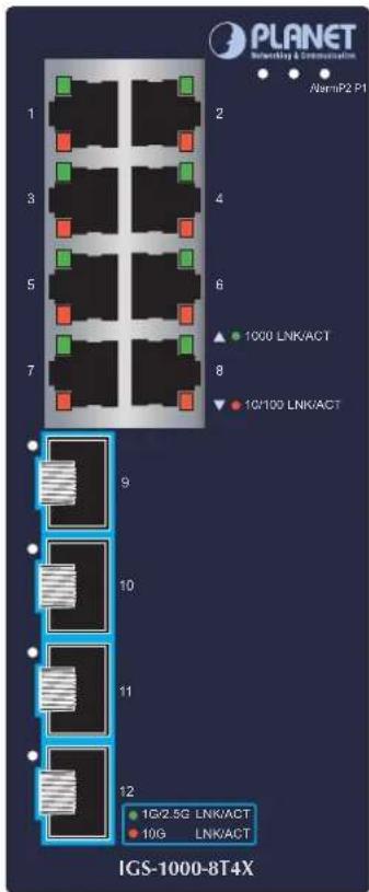
Figure 2-1: IGS-1000-8T4X front panel
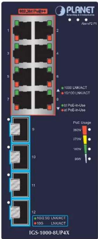
Figure 2-2: IGS-1000-8UP4X front panel
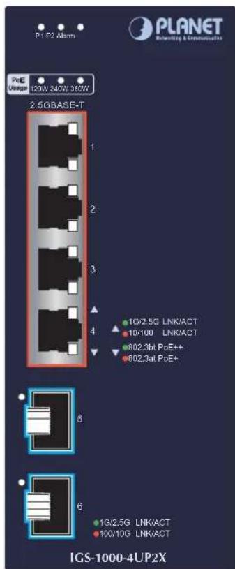
Figure 2-3: IGS-1000-4UP2X front panel
■ RJ45 Copper Interfaces
| Model Description Port No. | ||
| IGS-1000-8T4X Eight 10/100/1000BASE-T Port 1 to Port 8 | ||
| IGS-1000-8UP4X | Eight 10/100/1000BASE-T come with 802.3bt PoE++ type 4 injector function | Port 1 to Port 8 |
| IGS-1000-4UP2X | Four 10/100/1000/2500BASE-T come with 802.3bt PoE++ type 4 injector function | Port 1 to Port 4 |
■ 10Gigabit SFP+ Slots
| Model Description Port No. | ||
| IGS-1000-8T4X | Four 1G/2.5G/10GBASE-X SFP+ slots Port 9 to Port 12 | |
| IGS-1000-8UP4X | ||
| IGS-1000-4UP2X Two 1G/2.5G/10GBASE-X SFP+ slots Port 5 and Port 6 | ||
2.2 LED Indicators
IGS-1000-8T4X
■ System
| LED Color Function | ||
| P1 Green Lights: Indicates power 1 has power. | ||
| P2 Green Lights: Indicates power 2 has power. | ||
| Alarm | Red | Lights: Indicates either power 1 or power 2 has no power. |
■ 10/100/1000Mbps RJ45 Ports (Port 1 to Port 8)
| LED | Color | Function |
| 1000LNK/ACT | Green | Lights: To indicate the port is running at 1000Mbps and successfully established.Blinks: To indicate that the switch is actively sending or receiving data over that port. |
| 10/100LNK/ACT | Amber | Lights: To indicate the port is running at 10/100Mbps and successfully established.Blinks: To indicate that the switch is actively sending or receiving data over that port. |
■ 10GBASE-X SFP+ Interfaces (Port 9 to Port 12)
| LED | Color | Function |
| 1G/2.5GLNK/ACT | Green | Lights: To indicate the port is running at 1000Mbps or 2500Mbps and successfully established.Blinks: To indicate that the switch is actively sending or receiving data over that port. |
| 10GLNK/ACT | Amber | Lights: To indicate the port is running at 10Gbps and successfully established. |
IGS-1000-8UP4X
■ System
| LED Color Function | ||
| P1 Green Lights: Indicates power 1 has power. | ||
| P2 Green Lights: Indicates power 2 has power. | ||
| Alarm | Red | Lights: Indicates either power 1 or power 2 has no power. |
■ 10/100/1000Mbps RJ45 PoE++ Ports (Port 1 to Port 8)
| LED Color Function | ||
| 1000LNK/ACT | Green | Lights: To indicate the port is running at 1000Mbps and successfully established.Blinks: To indicate that the switch is actively sending or receiving data over that port. |
| 10/100LNK/ACT | Amber | Lights: To indicate the port is running at 10/100Mbps and successfully established.Blinks: To indicate that the switch is actively sending or receiving data over that port. |
| PoE-in-Use | Green | Lights: To indicate the PoE port is working in 4-pair PoE mode (End-span+Mid-span) and offers up to 95 watts of power. |
| Amber | Lights: To indicate the PoE port is working in 802.3at PoE+mode (End-span or mid-span) and offers up to 36 watts of power. | |
■ 10GBASE-X SFP+ Interfaces (Port 9 to Port 12)
| LED Color | Function | |
| 1G/2.5GLNK/ACT | Green | Lights: To indicate the port is running at 1000Mbps or 2500Mbps and successfully established.Blinks: To indicate that the switch is actively sending or receiving data over that port. |
| 10GLNK/ACT | Amber | Lights: To indicate the port is running at 10Gbps and successfully established. |
■ PoE Usage LED
| LED Color Function | ||
| 360W | Amber | Blinks: To indicate the system consumes close to 360-watt PoE power budget |
| 270W | Amber | Lights: To indicate the system consumes over 270-watt PoE power budget |
| 180W | Amber | Lights: To indicate the system consumes over 180-watt PoE power budget |
| 90W | Amber | Lights: To indicate the system consumes over 90-watt PoE power budget |
IGS-1000-4UP2X
■ System
| LED Color Function | ||
| P1 Green Lights: Indicates power 1 has power. | ||
| P2 Green Lights: Indicates power 2 has power. | ||
| Alarm | Red | Lights: Indicates either power 1 or power 2 has no power. |
■ 10/100/1000/2500Mbps RJ45 PoE++ Ports (Port 1 to Port 4)
| LED Color Function | ||
| 1G/2.5GLNK/ACT | Green | Lights: To indicate the port is running at 1000Mbps or 2500Mbps and successfully established.Blinks: To indicate that the switch is actively sending or receiving data over that port. |
| 10/100LNK/ACT | Amber | Lights: To indicate the port is running at 10/100Mbps and successfully established.Blinks: To indicate that the switch is actively sending or receiving data over that port. |
| PoE-in-Use | Green | Lights: To indicate the PoE port is working in 4-pair PoE mode (End-span+Mid-span) and offers up to 95 watts of power. |
| Amber | Lights: To indicate the PoE port is working in 802.3at PoE+ mode (End-span or mid-span) and offers up to 36 watts of power. | |
■ 10GBASE-X SFP+ Interfaces (Port 5 to Port 6)
| LED Color Function | ||
| 1G/2.5GLNK/ACT | Green | Lights: To indicate the port is running at 1000Mbps or 2500Mbps and successfully established.Blinks: To indicate that the switch is actively sending or receiving data over that port. |
| 100/10GLNK/ACT | Amber | Lights: To indicate the port is running at 100Mbps or 10Gbps and successfully established. |
■ PoE Usage LED
| LED Color Function | ||
| 360W | Amber | Blinks: To indicate the system consumes close to 360-watt PoE power budget |
| 240W | Amber | Blinks: To indicate the system consumes close to 240-watt PoE power budgetLights: To indicate the system consumes over 240-watt PoE power budget |
| 120W | Amber | Blinks: To indicate the system consumes close to 120-watt PoE power budgetLights: To indicate the system consumes over 120-watt PoE power budget |
2.3 Switch Upper Panel
The upper panel of the Industrial Ethernet Switch consists of one terminal block connector within two power input.
Figure 2-3 shows the upper panel of the IGS-1000-8T4X.
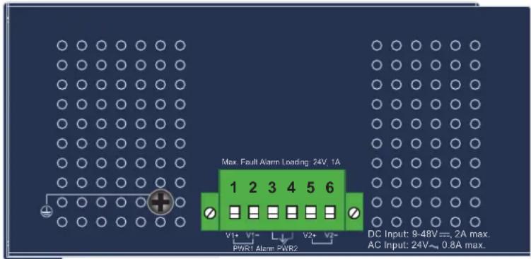
Figure 2-3: IGS-1000-8T4X Upper Panel
Figure 2-4 shows the upper panel of the IGS-1000-4UP2X and IGS-1000-8UP4X
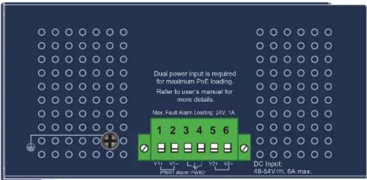
Figure 2-4: IGS-1000-4UP2X and IGS-1000-8UP4X Upper Panel
2.4 Wiring the Power Inputs
The 6-contact terminal block connector on the top panel of Industrial Ethernet Switch is used for two DC redundant power inputs. Please follow the steps below to insert the power wire.

Caution
When performing any of the procedures like inserting the wires or tightening the wire-clamp screws, make sure the power is OFF to prevent from getting an electric shock.
- Insert positive and negative DC power wires into Contacts 1 and 2 for Power 1, or Contacts 5 and 6 for Power 2.
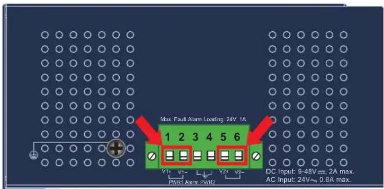
- Tighten the wire-clamp screws for preventing the wires from loosening.
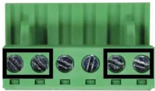
natural_image
Close-up of a green electronic component with five circular metallic components, no visible text or symbols.1 2 3 4 5 6
Power 1 Alarm Power 2
+ - + -

Note
- The wire gauge for the terminal block should be in the range between 12 and 24 AWG.
- The IGS-1000-8T4X supports DC input range of 9V to 48V.
The IGS-1000-4UP2X and IGS-1000-8UP4X supports DC input range of 48V to 54V.
To avoid damage, please use the IGS-1000 Series under its specification.

Caution
PWR1 and PWR2 must provide the same DC voltage while operating with dual power input.
2.5 Wiring the Fault Alarm Contact
The fault alarm contacts are in the middle of the terminal block connector as the picture shows below. Inserting the wires, the Industrial Ethernet Switch will detect the fault status of the power failure and then forms an open circuit. The following illustration shows an application example for wiring the fault alarm contacts.
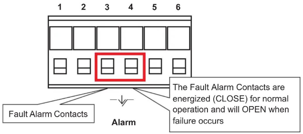
Insert the wires into the fault alarm contacts

Note
- The wire gauge for the terminal block should be in the range between 12 and 24 AWG.
- Alarm relay circuit accepts up to 24V with a maximum current of 1A.
2.6 Grounding the Device
Users MUST complete grounding wired with the device; otherwise, a sudden lightning could cause fatal damage to the device.
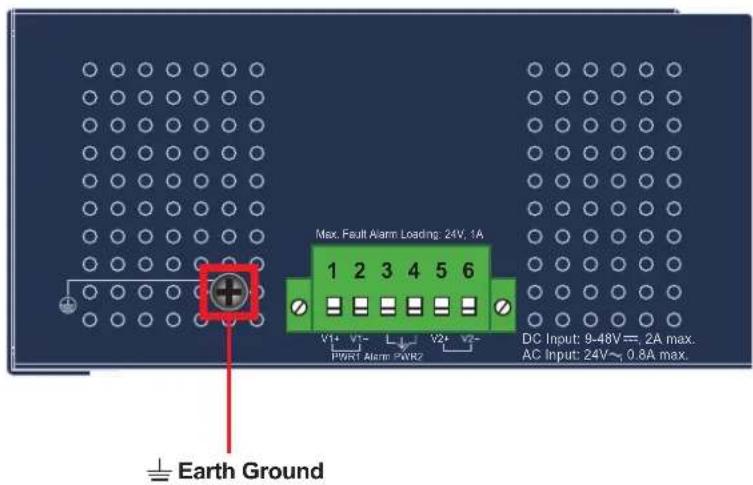

EMD (Lightning) DAMAGE IS NOT COVERED UNDER WARRANTY.
3. Installation
This section describes the functionalities of the Industrial Ethernet Switch's components and guides you to installing it on the DIN-rail and wall. Basic knowledge of networking is assumed. Please read this chapter completely before continuing.

Note
The installation procedures of the IGS-1000-8T4X and IGS-1000-8UP4X are the same as those shown below.
3.1 DIN-rail Mounting Installation
■ IGS-1000-8T4X and IGS-1000-8UP4X
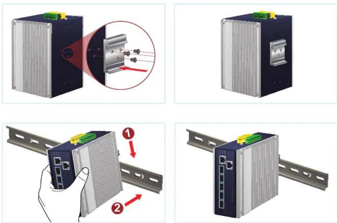
* The above pictures are for illustration only.
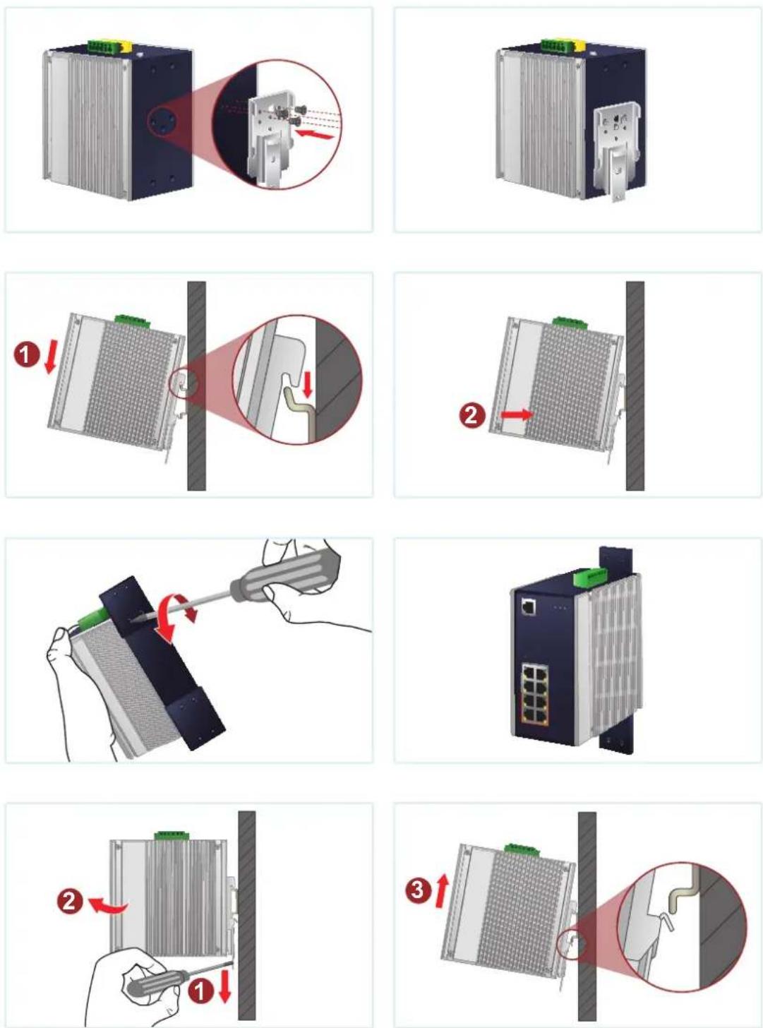
3.2 Wall-mount Plate Mounting

natural_image
Illustration of hands using a screwdriver to adjust or install a textured panel (no text or symbols visible)* The above pictures are for illustration only.
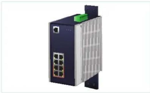
natural_image
3D rendering of a network switch device with ports and ventilation slots (no text or symbols visible)
Caution
You must use the screws supplied with the wall-mounting brackets. Damage caused to the parts by using incorrect screws would invalidate your warranty.
- Product Specifications
| Model IGS-1000-8T4X IGS-1000-8UP4X IGS-1000-4UP2X | |||
| Hardware Specifications | |||
| Copper Ports | 810/100/1000BASETRJ45 auto-MDI/MDI-X ports | 810/100/1000BASETRJ45 auto-MDI/MDI-X ports | 410/100/1000/2500BASETRJ45 auto-MDI/MDI-X ports |
| PoE InjectorPorts | -- | 8 ports with802.3bt PoE++injector function(Ports 1 to 8) | 4 ports with802.3bt PoE++injector function(Ports 1 to 4) |
| SFP+ Slots | 4 10GBASE-X SFP+interfaces(Ports 9 to 12)Backwardcompatible with1000BASE-X and2500BASE-X SFPtransceivers | 4 10GBASE-X SFP+interfaces(Ports 9 to 12)Backwardcompatible with1000BASE-X and2500BASE-X SFPtransceivers | 2 10GBASE-X SFP+interfaces(Ports 5 to 6)Backwardcompatible with100BASE-FX, 1000BASE-Xand 2500BASE-X SFPtransceivers |
| Connector | Removable 6-pin terminal blockPin 1/2 for Power 1Pin 3/4 for fault alarmPin 5/6 for Power 2 | ||
| PowerRequirements | 9~48V DC, 4A max.Redundant powerwith reverse polarityprotection function | 48~54V DC, 8A max.Redundant powerwith reverse polarityprotection function | |
| PowerConsumption | Max. 14.73watts/50.2BTU | Max. 8.69watts/29.6BTU(System on)Max. 387.2watts/1320BTU(Ethernet + PoE FullLoading) | Max. 4.86watts/16.6BTU(System on)Max. 372watts/1268.5BTU(Ethernet + PoE FullLoading) |
| Dimensions(W x D x H) | 76 x 135 x 152 mm | 76 x 135 x 152 mm | 76.8 x 107.3 x 152 mm |
| Weight 1213g | 1349g 1018g | ||
| Enclosure IP30 aluminum case | |||
| Installation | DIN-rail kit and wall-mount kit* Please note that the DIN-rail kit for the IGS-1000-4UP2X is different from that of the other two models. | ||
| ESD Protection | ±8KV air gap discharge±4KV contact discharge | ||
| Surge Immunity | ±5KV | ||
| LED Indicators | System:P1, P2 (Green),Alarm (Red) | System:P1, P2 (Green),Alarm (Red) | System:P1, P2 (Green),Alarm (Red) |
| 10/100/1000BASE-T RJ45 Interfaces (Port 1 to Port 8):1000Mbps LNK/ACT (Green)10/100Mbps LNK/ ACT (Amber) | 10/100/1000BASE-T RJ45 Interfaces (Port 1 to Port 8):1000Mbps LNK/ACT (Green)10/100Mbps LNK/ ACT (Amber)802.3bt PoE-in-Use (Green)802.3at PoE-in-Use (Amber) | 10/100/1000/2500BASE-T RJ45 Interfaces (Port 1 to Port 4):1000/2500Mbps LNK/ACT (Green)10/100Mbps LNK/ACT (Amber)802.3bt PoE-in-Use (Green)802.3at PoE-in-Use (Amber) | |
| Per 1G/2.5G/10Gbps SFP+ Interfaces1G/2.5Gbps LNK/ACT (Green)100/10Gbps LNK/ACT (Amber) | |||
| PoE Usage:90W, 180W, 270W,360W (Amber) | PoE Usage:120W, 240W, 360W (Amber) | ||
| Switch Specifications | |||
| Switch Architecture | Store-and-Forward | ||
| Switch Fabric | 96Gbps 96Gbps 60Gbps | ||
| Throughput (packet per second) | 71.43Mpps@64bytes | 71.43Mpps@64bytes | 44.462Mpps@64bytes |
| Address Table | 16K entries 16K entries | 4K entries | |
| Buffer Memory | 12M bits on-chip buffer memory | 12M bits on-chip buffer memory | 8M bits on-chip buffer memory |
| Jumbo Frame | 9Kbytes 9Kbytes 12Kbytes | ||
| Flow Control | Back pressure for half duplexIEEE 802.3x pause frame for full duplex | ||
| Power over Ethernet | |||
| PoE Standard | -- | IEEE 802.3bt PoE++ PSEBackward compatible with IEEE 802.3at PoE+PSE | |
| PoE Power Supply Type | -- | 802.3bt, End-span+ Mid-span | |
| PoE Power Output | -- | 95 watts max. | |
| Power Pin Assignment | -- | End-span+ Mid-span: 1/2(-), 3/6(+), 4/5(+), 7/8(-) | |
| PoE Power Budget (max.) | -- | Single power input: 240W maximumDual power input: 360W maximum | |
| Standards Conformance | |
| Regulatory Compliance | FCC Part 15 Class A, CE |
| Stability Testing | IEC 60068-2-32 (free fall)IEC 60068-2-27 (shock)IEC 60068-2-6 (vibration) |
| Standards Compliance | IEEE 802.3 EthernetIEEE 802.3u Fast EthernetIEEE 802.3ab Gigabit EthernetIEEE 802.3z Gigabit SX/LXIEEE 802.3ae 10 Gigabit EthernetIEEE 802.3x Full-Duplex Flow ControlIEEE 802.3bt Power over Ethernet Plus Plus PSE(For IGS-1000-8UP4X and IGS-1000-4UP2X)IEEE 802.3at Power over Ethernet Plus PSE(For IGS-1000-8UP4X and IGS-1000-4UP2X)IEEE 802.3af Power over Ethernet Plus(For IGS-1000-8UP4X and IGS-1000-4UP2X)IEEE 802.1p Class of ServiceIEEE 802.3bz 2.5GBASE-T(For and IGS-1000-4UP2X) |
| Environment | |
| Temperature | Operating: -40~75 degrees CStorage: -40~75 degrees C |
| Humidity | Operating: 5~90% (non-condensing)Storage: 5~90% (non-condensing) |
5. Customer Support
Thank you for purchasing PLANET products. You can browse our online FAQ resource at the PLANET Web site first to check if it could solve your issue. I support information, please contact PLANET support team.
PLANET online FAQs: https://www.planet.com.tw/en/support/faq
Support team mail address: support@planet.com.tw
Copyright © PLANET Technology Corp. 2024.
Contents are subject to revision without prior notice.
PLANET is a registered trademark of PLANET Technology Corp.
All other trademarks belong to their respective owners.
FCC Warning
This device has been tested and found to comply with the limits for a Class A digital device, pursuant to Part 15 of the FCC Rules. These limits are designed to provide reasonable protection against harmful interference when the equipment is operated in a commercial environment. This equipment generates, uses, and can radiate radio frequency energy and, if not installed and used in accordance with the Instruction manual, may cause harmful interference to radio communications. Operation of this equipment in a residential area is likely to cause harmful interference in which case the user will be required to correct the interference at his own expense.
WEEE Warning

To avoid the potential effects on the environment and human he result of the presence of hazardous substances in electrical and electronic equipment, end users of electrical and electronic equipment should understand the meaning of the crossed-out wheeled bin symbol. Do not dispose of WEEE as unsorted municipal waste and have to collect such WEEE separately.