KITBZPOWUK - Uncategorized StarTech.com - Free user manual and instructions
Find the device manual for free KITBZPOWUK StarTech.com in PDF.

| Product Type | Uninterruptible Power Supply (UPS) / Battery Backup |
| Brand | StarTech.com |
| Model | KITBZPOWUK |
| Input Voltage | 100–240 V AC, 50/60 Hz |
| Output Voltage | 5 V DC (USB) or 12 V DC (depending on model) |
| Battery Type | Lithium-ion (Li-ion), rechargeable |
| Battery Capacity | 2000 mAh (estimated) |
| Dimensions (L x W x H) | 12.5 x 7.5 x 2.5 cm (approx.) |
| Weight | 200 g (approx.) |
| Charging Time | 2–3 hours (estimated) |
| Run Time (half load) | 30–60 minutes (estimated) |
| Output Ports | 1 x USB-A, 1 x DC barrel |
| Protection Features | Overcharge, over-discharge, short-circuit, surge protection |
| Operating Temperature | 0°C to 40°C |
| Storage Temperature | -10°C to 50°C |
| Compliance | CE, FCC, RoHS |
| Included Accessories | USB charging cable, user manual |
| Maintenance | Keep dry, avoid extreme temperatures, charge periodically |
| Safety Instructions | Do not disassemble, use only with compatible devices |
| Repairability | Battery is replaceable by professional (non-user serviceable) |
Frequently Asked Questions - KITBZPOWUK StarTech.com
User questions about KITBZPOWUK StarTech.com
0 question about this device. Answer the ones you know or ask your own.
Ask a new question about this device
Download the instructions for your Uncategorized in PDF format for free! Find your manual KITBZPOWUK - StarTech.com and take your electronic device back in hand. On this page are published all the documents necessary for the use of your device. KITBZPOWUK by StarTech.com.
USER MANUAL KITBZPOWUK StarTech.com
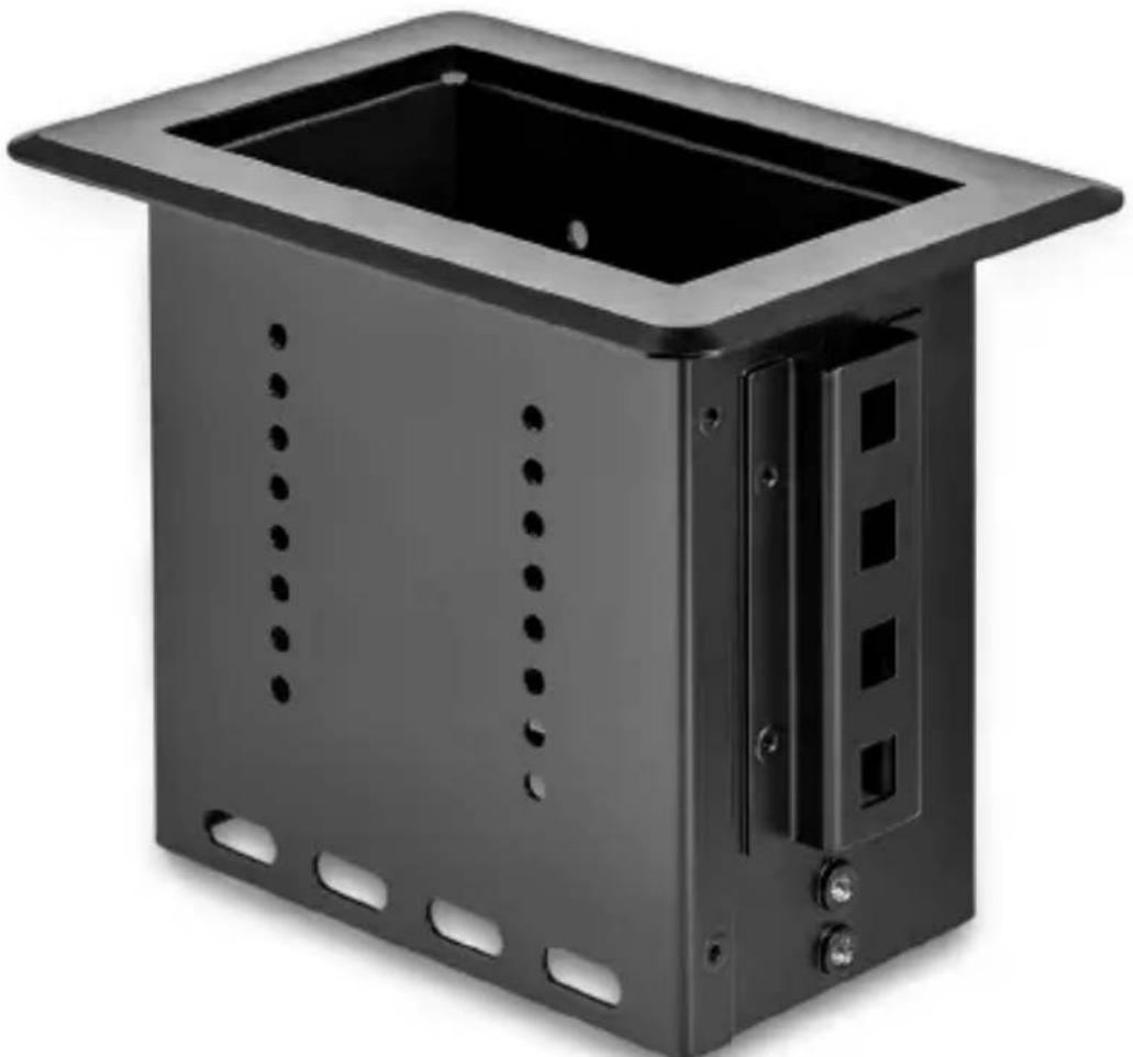
Single-Module Conference Table Box
natural_image
Exterior view of a black metal enclosure with rectangular top and side cutouts (no text or symbols)Actual product may vary from photos
User Manual
SKU#: BEZ4MOD
Compliance Statements
Use of Trademarks, Registered Trademarks, and other Protected Names and Symbols
This manual may make reference to trademarks, registered trademarks, and other protected names and/or symbols of third-party companies not related in any way to StarTech.com. Where they occur these references are for illustrative purposes only and do not represent an endorsement of a product or service by StarTech.com, or an endorsement of the product(s) to which this manual applies by the third-party company in question. Regardless of any direct acknowledgement elsewhere in the body of this document, StarTech.com hereby acknowledges that all trademarks, registered trademarks, service marks, and other protected names and/or symbols contained in this manual and related documents are the property of their respective holders.
Safety Statements
Safety Measures
- Wiring terminations should not be made with the product and/or electric lines under power.
- Product installation and/or mounting should be completed by a certified professional as per the local safety and building code guidelines.
- Cables (including power and charging cables) should be placed and routed to avoid creating electric, tripping or safety hazards.
Mesures de sécurité
Make sure to assemble this product according to the instructions. Failure to do so might result in personal injury or property damage.
Never use this product if parts are missing or damaged.
To view manuals, videos, drivers, downloads, and more visit www.startech.com/support
Table of Contents
Compliance Statements....1
Safety Statements....1
Warning Statements 2
Product Diagram 4
Product Information 5
Package Contents ....5
Requirements 6
Installation 7
Cutting the Table/Surface 7
Installing the Module in the Modular Table Box....10
Installing the Lacing Bar (Cable Organization)....13
Installing the Modular Table Box into a Surface.... 14
Assembling the Cable Management Module 16
Assembly Requirements: 16
Installing the Cable Management Module....17
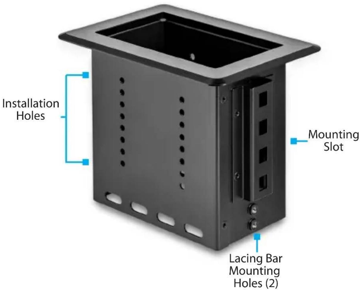
Product Diagram
Product Information
Package Contents
BOX4MODULE
- Modular Table Box x 1
-
Installation Kit
-
Wing Fastener x 2
• Die Cut Outline x 1 - Lacing Bar x 1
• Lacing Bar Screws (M4 x 4 mm) x 4
• Cable Management Module
• Cable Management Bracket x 1
• Cable Management Top Plates x 2
- Cable Management Plate Screws (#6-32 x 3/8") x 4
- Cable Management Bracket Mounting Screws (#6-32 x 3/8") x 4
- Small Cable Bushing x 1
• Large Cable Bushing x 1
- User Manual x 1
Requirements
Installation:
Installation requirements are sold separately.
• Surface for Installation
- Cable Ties
- Tools
• 3/8 Wood Drill Bit x 1
• Phillips Head Screwdriver x 1
- Jigsaw x 1
- Drill x 1
- Writing Utensil x 1
- Painter's Tape x 1
Module:
Module requirements are optional and will depend on the configuration needed for the Conference Table setup. Modules to choose from include:
- Docking Station Module (MOD4DOCKACPD)
• Cable Management Module (MOD4CABLEH)
Note: Half size module included, additional cable management brackets sold separately.
• Power Module (MOD4POWERNA, MOD4POWEREU, or MOD4POWERUK)
• A/V Connectivity Module (MOD4AVHD)
• A/V Module with HDMI over CAT5e/CAT6 (MOD4AVHDBT)
Installation
For additional information on installing the Modular Table Box, please visit www.startech.com/BEZ4MOD to watch the installation video.
Notes: StarTech.com is not responsible for any damages related to the installation of this product.
Prior to installation, please test the product's port compatibility with all devices and displays intended for use with this product.
The thickness of the table surfaced used for installation should not exceed 2.25 inches.
Cutting the Table/Surface
Note: Check the underside of the table/surface you are installing the Modular Table Box into to ensure that there are no obstructions that may interfere with the installation.
- Carefully cut along the dotted guideline on the Die Cut Outline, cutting off the four edges of the Die Cut Outline, leaving the inner Surface Cut-Out Area intact.
Note: The Die Cut Outline has been created with a built in margin of error of 1/16" (1.5 mm) in either direction of the marked cut line, to compensate for any deviation while cutting out the Surface Cut-Out Area.
-
Before cutting the surface of the table, measure and align the Surface Cut-Out Area (created in step 1) into the desired position on the table's surface. Tape the Surface Cut-Out Area in place using Painter's Tape.
-
Using a Writing Utensil, trace around the Surface Cut-Out Area to create a guide on the table's surface.

Surface Cut-Out Area
-
Carefully remove the Surface Cut-Out Area from the table's surface.
-
Using a Drill with a 3/8" Wood Drill Bit, carefully drill pilot holes in each of the four corners of the guide.
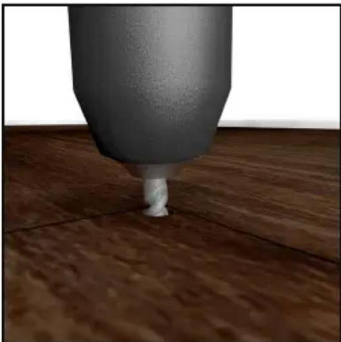
natural_image
Close-up of a sculpted cylindrical object on a wooden floor, no visible text or symbolsDrill Pilot Holes
- Insert the Jigsaw Blade into one of the pilot holes and carefully cut into the surface, along the guide lines to connect the four pilot holes, cutting the installation hole out of the table's surface.
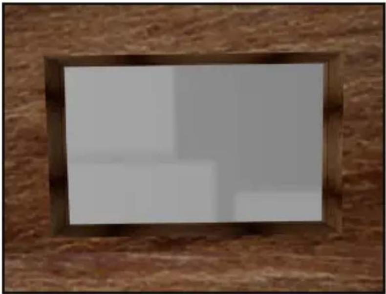
natural_image
Wooden brick wall with a rectangular frame showing a blank white image (no text or symbols visible)Installation Hole
Installing the Module in the Modular Table Box
Notes: Modules can be mounted using three different mounting depths depending on your conference table setup.
See Assembling the Cable Module and Installing the Cable Module if you intend to use the Cable Module in your Modular Table Box configuration.
- Determine the mounting depth of the Module inside the Modular Table Box. Take into consideration cable bend radius and the amount of clearance needed to properly close the Modular Table Box lid while cables are connected to the Module.
To view manuals, videos, drivers, downloads, and more visit www.startech.com/support
Notes: Before installing a Module into the Modular Table Box, connect each of the conference room devices to the bottom of the Module (see Connecting Devices to the Bottom of the Module or Connecting Devices to the Top of the Module sections in the Module's User Manual).
Connect the Universal Power Adapter to the bottom of the Module (see Powering the Module section in the Module's User Manual).
-
When connecting conference room devices and power to the Module, feed the cables through the Modular Table Box from the bottom up and connect the required cables to the corresponding ports on the Module.
-
Insert the Module into the Modular Table Box.
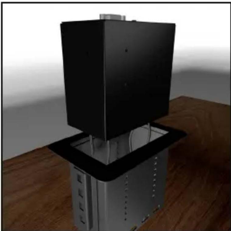
natural_image
3D rendering of a black server rack mounted on a metallic base, placed on a wooden table (no text or symbols visible)Insert Module into Modular Table Box
To view manuals, videos, drivers, downloads, and more visit www.startech.com/support
- Align the Module with the Installation Holes on both sides of the Modular Table Box.
- Insert the Module Screws (x 8, 4 per side) through the Installation Holes on the Modular Table Box and into the Mounting Holes on the Module.
Note: The eight Module Screws are packaged with the Module.
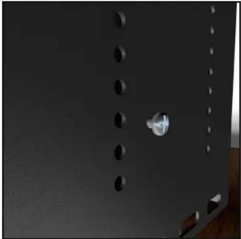
natural_image
Close-up of a dark metal panel with multiple circular indentations and a central metallic knob (no text or symbols visible)Inserting Module Screws
- Using a Phillips Head Screwdriver, tighten the Module Screws. Be careful not to overtighten.
Installing the Lacing Bar (Cable Organization)
-
On the Modular Table Box or Single Modular Table Box, align the Mounting Holes on the Lacing Bar with the Mounting Holes on the Modular Table Box.
-
Insert the Lacing Bar Screws (2 per side) through the Mounting Holes on the Lacing Bar and into the Modular Table Box.
Note: The Modular Table Box has three Lacing Bar mounting options (left, center, and right). Mount the Lacing Bar in the position that best suits your needs.
natural_image
Close-up of a black door with metallic doorrests and a white panel, set against a wooden floor and bright light (no text or symbols visible)Installing the Lacing Bar
To view manuals, videos, drivers, downloads, and more visit www.startech.com/support
- Using a Phillips Head Screwdriver, tighten the Lacing Bar Screws. Be careful not to overtighten.
- Using Cable Ties (sold separately), attach the cables connected to the Module(s) to the Lacing Bar.
Note: The Lacing Bar is used for cable management and can help reduce cable strain, bend radius, unintentional cable disconnects and improve organization.
Installing the Modular Table Box into a Surface
- Place the Modular Table Box (sold separately or included in a bundle) into the hole in the table's surface.
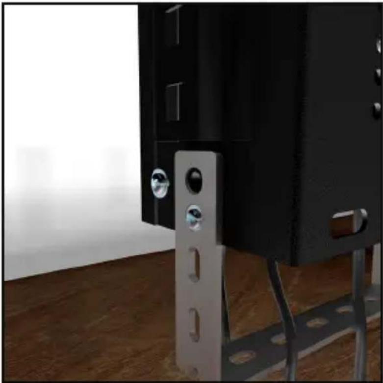
- Under the table's surface, slide the Wing Fasteners (1 per side) into a Mounting Slot on the Mounting Bracket. The Mounting Slot you use will be determined by the height of the table's surface.
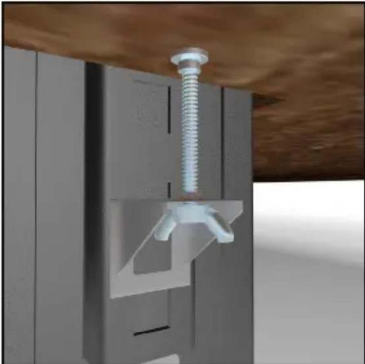
natural_image
3D rendering of a mechanical assembly with a metallic screw and bracket (no text or symbols visible)Installing the Wing Fasteners
To view manuals, videos, drivers, downloads, and more visit www.startech.com/support
- Secure the Modular Table Box in place by tightening each of the Wing Fasteners until the top of the nut comes in contact with the bottom of the table's surface, creating a tight seal between the table's surface and the Modular Table Box. Be careful not to overtighten the Wing Fasteners.
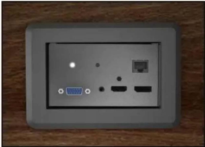
natural_image
Front panel of a wall-mounted electronic device showing ports and indicators (no readable text or symbols)Modular Table Box
Assembling the Cable Management Module
The Cable Management Module is used to organize up to 2 cables in the Modular Table Box.
Assembly Requirements:
- Modular Table Box (SKU: BEZ4MOD or BOX4MODULE) x 1
• Cable Management Module x 1
• Cable Management Bracket x 1 - Small Cable Bushing x 1
• Large Cable Bushing x 1
• Cable Management Plate x 2 - Plate Screws (#6-32 x 3/8) x 4
- Bracket Screws (#6-32 x 3/8) x 4
- Tools
• Phillips Head Screwdriver x 1
- Align one of the Cable Management Plates with the Plate Screw Holes and Bushing Holes on the top of the Cable Management Bracket. Insert 2 of the Plate Screws through the Cable Management Plate and into the Cable Management Bracket.
- Using the Phillips Head Screwdriver tighten the 2 Plate Screws, securing the Cable Management Plate in place. Be careful not to over tighten the Plate Screws.
- Insert one cable (max 7.9 mm diameter) through the slit in the Small Cable Bushing. Using just enough force to get the cable through the slit without damaging the bushing.
- Insert one cable (max 14.5 mm diameter) through the slit in the Large Cable Bushing. Using just enough force to get the cable through the slit without damaging the bushing.
-
Feed the cables through the bottom of the Cable Management Bracket.
-
Align the other Cable Management Plate with the Plate Screw Holes and Bushing Holes on the top of the Cable Management Bracket. Insert 2 of the Plate Screws, through the Cable Management Plate and into the Cable Management Bracket.
- Using the Phillips Head Screwdriver tighten the 2 Plate Screws, securing the Cable Management Plate in place. Be careful not to over tighten the Plate Screws.
- Carefully push the Cable Bushings into the designated Bushing Holes, snapping them into place.
Installing the Cable Management Module
If you intend to use the Cable Management Module in your Modular Table Box configuration you will need to install it at the same time you are installing the other Modules.
- Determine the mounting depth of the Module inside the Modular Table Box. Consider the cable bend radius and the amount of clearance needed to properly close the Modular Table Box lid while cables are connected to the Module.
- Insert the Module into the Modular Table Box.
- Align the Module with the Installation Holes on both sides on the Modular Table Box.
- Insert the Module Screws (x 4, 2 per side) through the Installation Holes on the Modular Table Box and into the Mounting Holes on the Module.
- Using a Phillips Head Screwdriver, tighten the Module Screws, be careful not to overtighten.
Technical Support
StarTech.com's lifetime technical support is an integral part of our commitment to provide industry-leading solutions. If you ever need help with your product, visit www.startech.com/support and access our comprehensive selection of online tools, documentation, and downloads.
For the latest drivers/software, please visit www.startech.com/downloads
Warranty Information
This product is backed by a two-year warranty.
StarTech.com warrants its products against defects in materials and workmanship for the periods noted, following the initial date of purchase. During this period, the products may be returned for repair, or replacement with equivalent products at our discretion. The warranty covers parts and labor costs only.
StarTech.com does not warrant its products from defects or damages arising from misuse, abuse, alteration, or normal wear and tear.
Limitation of Liability
In no event shall the liability of StarTech.com Ltd. and StarTech.com USA LLP (or their officers, directors, employees or agents) for any damages (whether direct or indirect, special, punitive, incidental, consequential, or otherwise), loss of profits, loss of business, or any pecuniary loss, arising out of or related to the use of the product exceed the actual price paid for the product.
Some states do not allow the exclusion or limitation of incidental or consequential damages. If such laws apply, the limitations or exclusions contained in this statement may not apply to you.
Hard-to-find made easy. At StarTech.com, that isn't a slogan. It's a promise.
StarTech.com is your one-stop source for every connectivity part you need. From the latest technology to legacy products — and all the parts that bridge the old and new — we can help you find the parts that connect your solutions.
We make it easy to locate the parts, and we quickly deliver them wherever they need to go. Just talk to one of our tech advisors or visit our website. You'll be connected to the products you need in no time.
Visit www.startech.com for complete information on all StarTech.com products and to access exclusive resources and time-saving tools.
StarTech.com is an ISO 9001 Registered manufacturer of connectivity and technology parts. StarTech.com was founded in 1985 and has operations in the United States, Canada, the United Kingdom and Taiwan servicing a worldwide market.
Reviews
Share your experiences using StarTech.com products, including product applications and setup, what you love about the products, and areas for improvement.
StarTech.com Ltd.
45 Artisans Cres.
London, Ontario
N5V 5E9
Canada
StarTech.com LLP
2500 Creekside Pkwy.
Lockbourne, Ohio
43137
U.S.A.
StarTech.com Ltd.
Unit B, Pinnacle
15 Gowerton Rd., Brackmills
Northampton
NN4 7BW
United Kingdom
FR: fr.startech.com
DE: de.startech. com
ES: es.startech.com
NL: nl.startech.com
IT: it.startech.com
JP: jp.startech.com