AP345 - Access Point IP-COM - Free user manual and instructions
Find the device manual for free AP345 IP-COM in PDF.

User questions about AP345 IP-COM
0 question about this device. Answer the ones you know or ask your own.
Ask a new question about this device
Download the instructions for your Access Point in PDF format for free! Find your manual AP345 - IP-COM and take your electronic device back in hand. On this page are published all the documents necessary for the use of your device. AP345 by IP-COM.
USER MANUAL AP345 IP-COM
©2018 IP-COM Networks Co., Ltd. All rights reserved.
IP-COM is the registered trademark of IP-COM Networks Co., Ltd. Other brand and product names mentioned herein are trademarks or registered trademarks of their respective holders. Copyright of the whole product as integration, including its accessories and software, belongs to IP-COM Networks Co., Ltd. No part of this publication can be reproduced, transmitted, transcribed, stored in a retrieval system, or translated into any language in any form or by any means without the prior written permission of IP-COM Networks Co., Ltd.
Disclaimer
Pictures, images and product specifications herein are for references only. To improve internal design, operational function, and/or reliability, IP-COM reserves the right to make changes to the products described in this document without obligation to notify any person or organization of such revisions or changes. IP-COM does not assume any liability that may occur due to the use or application of the product or circuit layout(s) described herein. Every effort has been made in the preparation of this document to ensure accuracy of the contents, but all statements, information and recommendations in this document do not constitute the warranty of any kind, express or implied.
Preface
Thank you for choosing IP-COM! Please read this user guide before you start with AP345.
Conventions
The typographical elements that may be found in this document are defined as follows.
| Item Presentation Example | ||
| Cascading menus > | Network Settings > LAN Setup | |
| Parameter and value | Bold | Set SSID to Tom. |
| Variable | Italic | Format: XX:XX:XX:XX:XX:XX |
| UI control | Bold | On the Quick Setup page, click the Save button. |
The symbols that may be found in this document are defined as follows.
| Symbol Meaning | |
 | This format is used to highlight information of importance or special interest. Ignoring this type of note may result in ineffective configurations, loss of data or damage to device. |
 | This format is used to highlight a procedure that will save time or resources. |
Acronyms and Abbreviations
| Acronym or Abbreviation | Full Spelling |
| AC AP Controller | |
| AP Access Point | |
| DHCP Dynamic Host Configuration Protocol | |
| DNS Domain Name Server | |
| DTIM | Delivery Traffic Indication Message |
| GI Guard Interval | |
| ISP Internet Service Provider | |
Acronym or Abbreviation
Full Spelling
PPP Point to Point Protocol
SSID Service Set Identifier
VLAN Virtual Local Area Network
Additional Information
For more information, search this product model on our website at
http://www.ip-com.com.cn
Technical Support
If you need more help, contact us by any of the following means. We will be glad to assist you as soon as possible.

+86-755-27653089

info@ip-com.com.cn

http://www.ip-com.com.cn
Contents
1 Introduction .... 1
1.1 Overview.... 1
1.2 Appearance.... 1
1.2.1 LED indicator, button, and ports 1
1.2.2 Bottom label .... 3
2 Quick Setup 4
2.1 Overview....4
2.2 Deploying the AP without an IP-COM management router/AC 4
2.3 Deploying the AP with an IP-COM AP controller 8
2.4 Deploying the AP with an IP-COM router with AP control function.... 11
3 Login 12
3.1 Logging in to the web UI of the AP 12
3.2 Logging out of the web UI of the AP 13
3.3 Web UI layout 14
3.4 Common buttons.... 15
4 Status ....16
4.1 System status 16
4.2 Wireless status.... 18
4.3 Traffic statistics 20
4.4 Wireless clients 21
5 Working Mode....22
5.1 Overview....22
5.2 Setting WiFi network in AP mode 24
5.3 Setting WiFi network in Client+AP mode 25
6 Network Settings....27
6.1 LAN setup.... 27
6.2 Changing the LAN IP address of the AP 29
6.2.1 Dynamic IP address.... 29
6.2.2 Static IP address.... 29
6.3 DHCP server 31
6.3.1 Overview 31
6.3.2 Configuring the DHCP server 31
6.3.3 DHCP clients.... 33
7 Wireless Settings ....34
7.1 SSID settings.... 34
7.1.1 Overview.... 34
7.1.2 Changing the SSID settings 36
7.1.3 Examples 42
7.2 Radio settings....63
7.2.1 Overview 63
7.2.2 Changing the radio settings 63
7.3 Radio optimization....67
7.3.1 Overview....67
7.3.2 Changing the radio optimization settings....68
7.4 Frequency analysis.... 71
7.4.1 Overview 71
7.4.2 Checking frequency analysis.... 71
7.4.3 Detecting rogue APs.... 72
7.5 WMM settings 73
7.5.1 Overview 73
7.5.2 Changing the WMM settings.... 74
7.6 Access control.... 76
7.6.1 Overview 76
7.6.2 Configuring access control 76
7.6.3 Example.... 77
7.7 Advanced settings.... 79
7.7.1 Overview 79
7.7.2 Changing the advanced settings.... 79
7.8 QVLAN settings 81
7.8.1 Overview 81
7.8.2 Configuring the QVLAN settings 81
7.8.3 Example.... 82
8 SNMP 85
8.1 Overview 85
8.1.1 SNMP management framework 85
8.1.2 Basic SNMP operations 85
8.1.3 SNMP protocol version 86
8.1.4 MIB introduction.... 86
8.2 Configuring the SNMP function 87
8.3 Example 89
9 Deployment....91
9.1 Overview.... 91
9.2 Configuring the deployment mode.... 93
9.2.1 Configuring the local deployment mode 93
9.2.2 Configuring the cloud deployment mode.... 93
10 Tools....95
10.1 Firmware upgrade....95
10.2 Date & time....97
10.2.1 System time 97
10.2.2 Login timeout interval....99
10.3 Logs.... 100
10.3.1 Logs 100
10.3.2 Configuring log settings 101
10.4 Configuration 104
10.4.1 Backup and restoring configurations 104
10.4.2 Resetting the AP.... 105
10.5 Account.... 107
10.6 Diagnostics tool.... 108
10.6.1 Locating the faulty node 108
10.7 Reboot device 109
10.7.1 Manual reboot.... 109
10.7.2 Reboot schedule 109
10.8 LED control.... 111
10.9 Uplink check.... 112
10.9.1 Overview.... 112
10.9.2 Configuring uplink check.... 112
Appendix....114
1 Introduction
1.1 Overview
AP345 is a dual band (2.4/5 GHz) wireless access point offering a wireless transmission rate as high as 1200 Mbps. It can be powered on by DC power supply or IEEE 802.3af/at PoE power supply. Users can manage the AP through its web UI, or by an IP-COM wireless AP controller or an IP-COM router with AP controller (AC) function. In addition, its ceiling design makes it suitable for WiFi coverage in multiple places, such as hotels and enterprises.
1.2 Appearance
This section describes the LED indicator, button, ports, and bottom label of your AP.
1.2.1 LED indicator, button, and ports
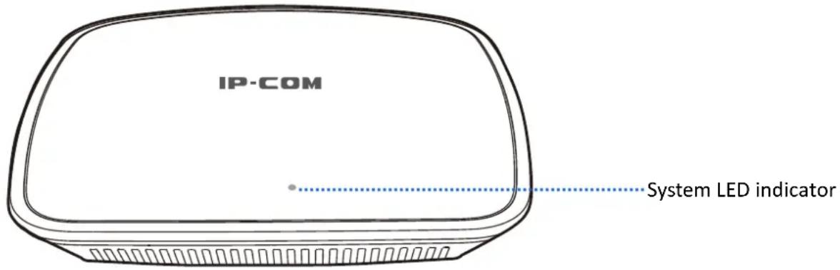
System LED indicator
| System LED indicator | Solid on | - The system is starting. - If the indicator keeps solid on after the AP finishes startup, it indicates that the system is faulty. |
| Blinking | The AP is working properly. | |
| Off | - The AP is not powered on. - The LED indicator has been turned off. - The AP is faulty. |
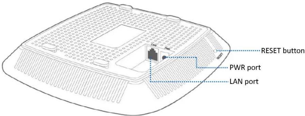
RESET button
When the system LED indicator blinks, hold down the RESET button for about 8 seconds. The AP is reset successfully when the system LED indicator gets solid on.
LAN port
It is a 10/100 Mbps auto-negotiation port used to exchange data with other devices or connect to IEEE 802.3af/at PoE power supply using an Ethernet cable to power on the AP.
PWR port
It is a power port used to connect to a DC power resource using the power adapter included in the package.
1.2.2 Bottom label
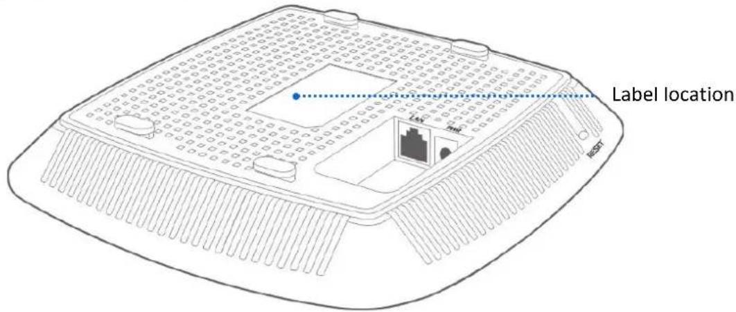
The bottom label shows the AP's default IP address, login username and password, input DC power supply, and serial number. See the following figure:
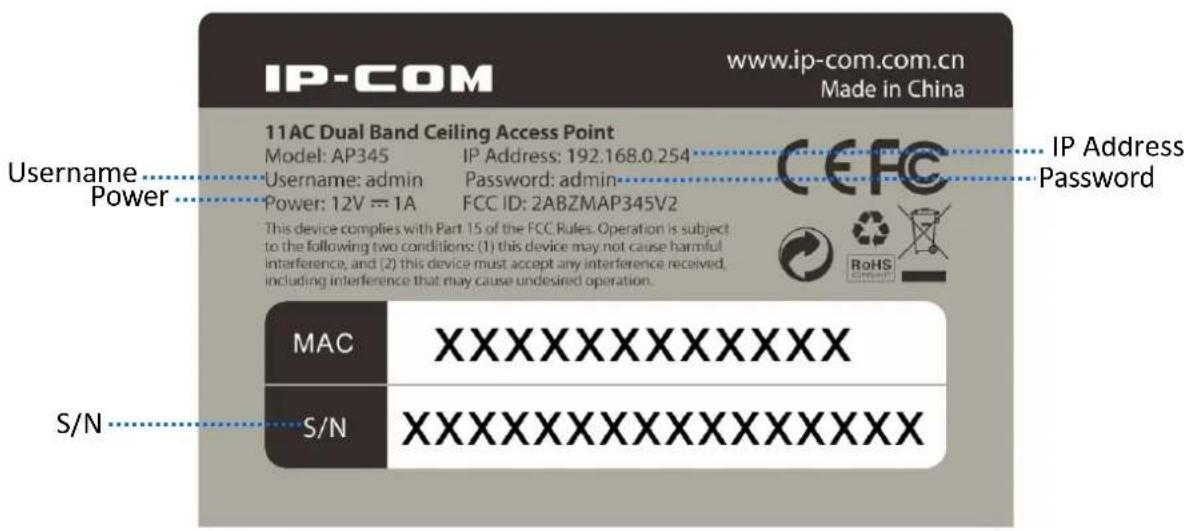
IP Address: It specifies the default IP address of the AP. You can use this IP address to log in to your AP's web UI when you set it for the first time. After you change the IP address, you should use the new IP address to log in to its web UI.
Username/Password: It specifies the default login username/password used to log in to the web UI of the AP. After you change the username/password, you should use the new username/password to log in to its web UI.
Power: It specifies the input DC power supply of the AP.
S/N: It specifies the serial number of the AP. If the AP is faulty, you need to provide this serial number for repair.
2 Quick Setup
2.1 Overview
This chapter is about how to set up APs in different scenarios. Please select one according to your scenario.
2.2 Deploying the AP without an IP-COM management router/AC
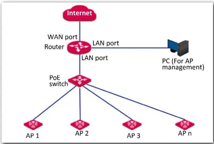
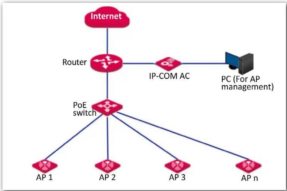
1. Connect devices.
(1) Ensure that your router is connected to the internet.
(2) Ensure that your router and PoE switch are connected to power supply.
(3) Connect your computer and PoE switch to LAN ports of the router using Ethernet cables.
(4) Connect LAN port of your AP to a PoE port of your PoE switch using an Ethernet cable.
The network topology is shown as follows:
flowchart
graph TD
    A["Internet"] --> B["WAN port Router"]
    A --> C["LAN port"]
    B --> D["POE switch"]
    C --> D
    D --> E["AP 1"]
    D --> F["AP 2"]
    D --> G["AP 3"]
    D --> H["AP n"]
    C --> I["PC (For AP management)"]

Note
- If you choose to power on your AP using DC power supply, connect the PWR port of your AP to a DC power resource using the included power adapter.
- If you have several IP-COM APs, to avoid IP address conflict, you should connect one AP to a PoE port of your PoE switch first and set a new IP address for the AP. Then repeat this procedure to connect other APs one by one and configure new IP addresses for them respectively.
After finishing connection, ensure that the AP's LED indicator blinks and the lower-right network icon on your computer is not displayed
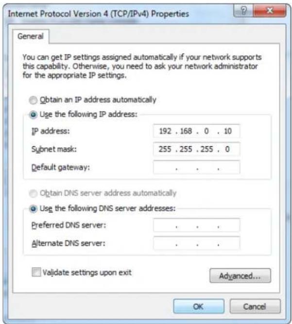
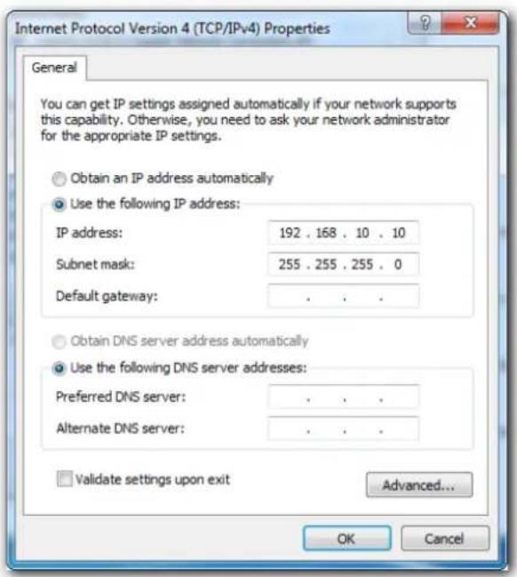
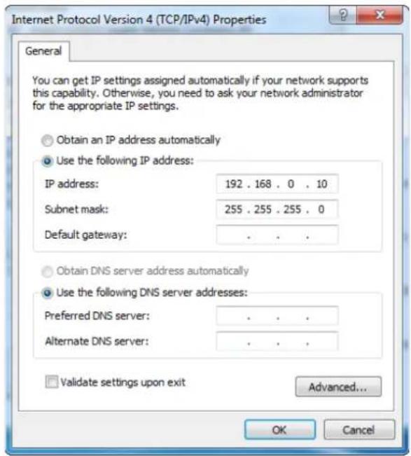
- Configure the IP address of your computer (Example: Win7).
(1) Right-click the network icon on the lower-right corner of your computer. Then click Open Network and Sharing Center, Local Area Connection, and Properties.
(2) Double-click Internet Protocol Version 4 (TCP/IPv4), select Use the following IP address, set IP address to 192.168.0.x (x: 2 to 253. The IP address in this example is 192.168.0.10) and Subnet mask to 255.255.255.0.
(3) Click OK.
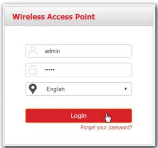
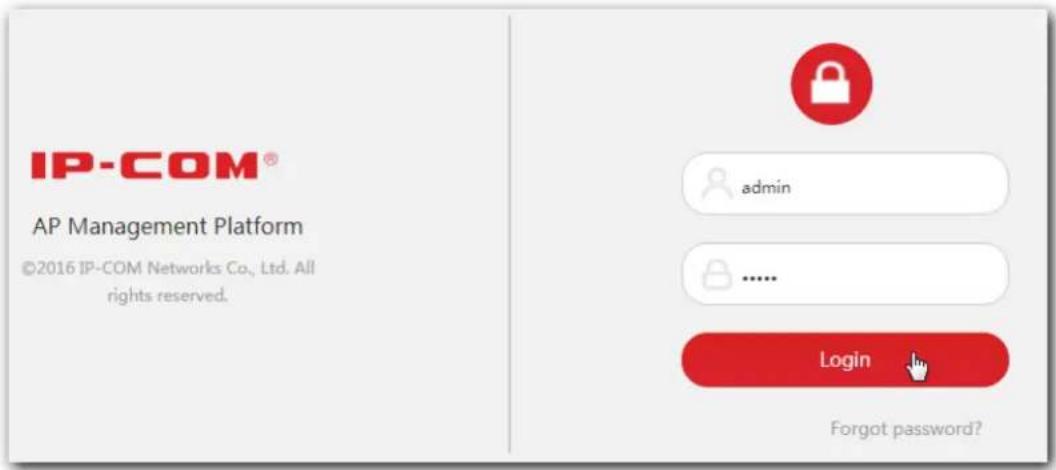
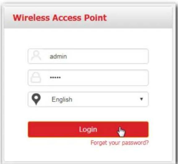
- Log in to the web UI of your AP.
(1) Start a web browser on your computer. Enter 192.168.0.254 in the address bar, and press Enter.
(2) Enter the user name and password (default: admin/admin) of the AP.
(3) Click Login.
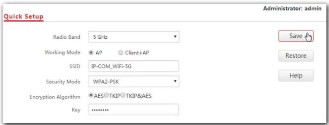
- Set SSID (WiFi name) and key (WiFi password) for the WiFi network of your AP.
(1) To access the configuration page, click Quick Setup.
(2) Configure SSID, Security Mode (WPA2-PSK is recommended), Key for the 2.4 GHz WiFi network, and click Save.
(3) Set Radio Band to 5 GHz, configure SSID, Security Mode and Key for it as well, and click Save.
- Change the IP address of your AP.
(1) To access the configuration page, click Network Settings > LAN Setup.
(2) IP Address: Change the IP address of the AP to 192.168.0.x (x: 2 to 253), which is 192.168.0.250 in this example.
(3) Click Save.
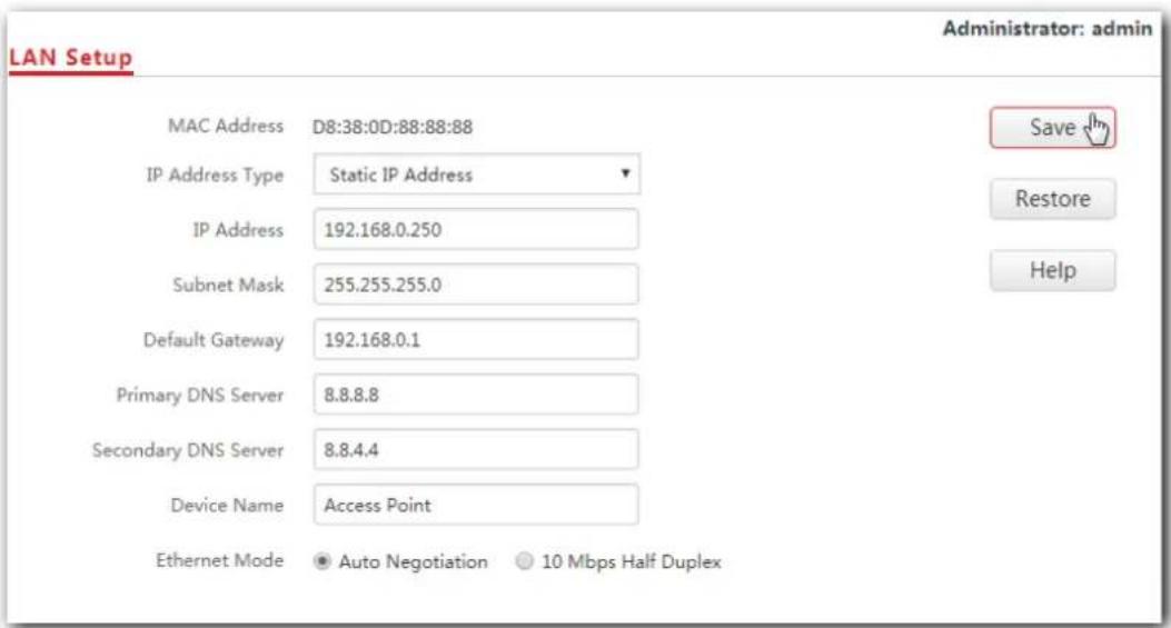
Wait a moment to apply the settings.

Note
The new IP address you set for the AP should not been used by other devices in the same LAN network, and the IP address of your management computer should be in the same network segment as that of the new IP address.
- Connect your wireless devices like smart phones to the WiFi network of your AP using the WiFi name and password you set in step 4.
---End
2.3 Deploying the AP with an IP-COM AP controller
A hotel may be deployed with lots of APs, so you are recommended to use an IP-COM AP controller (AC) to manage the APs centrally. The following describes the procedures.
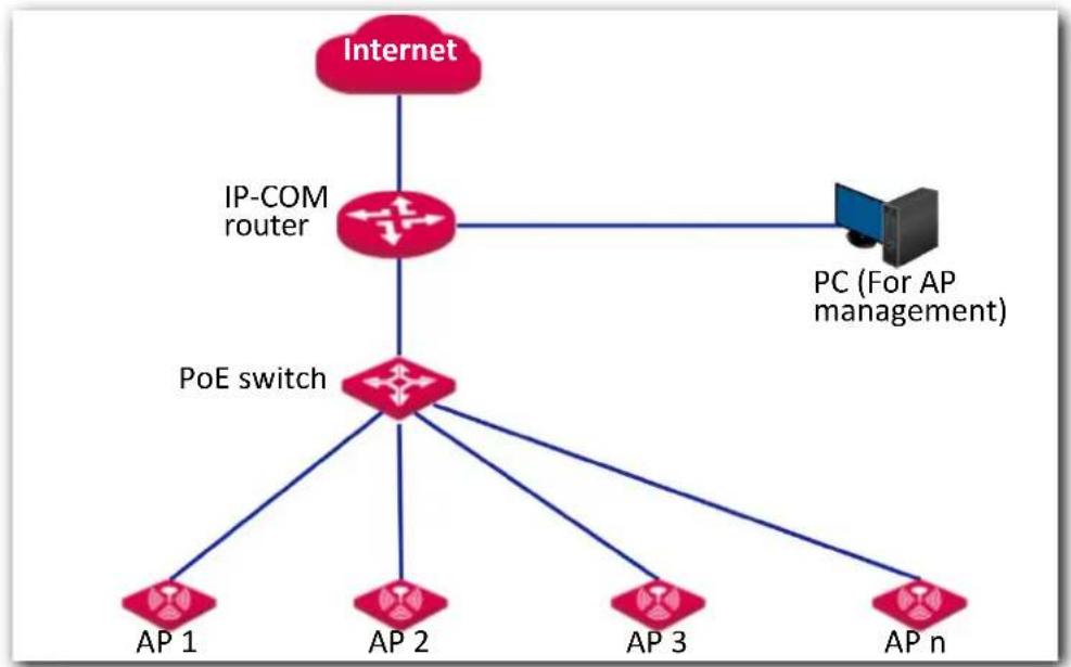
- Connect devices.
(1) Ensure that your router is connected to the internet.
(2) Ensure that your router, PoE switch and AC are connected to power supply.
(3) Connect your IP-COM AC and PoE switch to LAN ports of your router using Ethernet cables. IP-COM AC2000 is used for instructions in this example.
(4) Connect your APs to PoE ports of your PoE switch using Ethernet cables.
(5) Connect your computer to a port of your AC.
flowchart
graph TD
    A["Internet"] --> B["Router"]
    B --> C["IP-COM AC"]
    B --> D["PoE switch"]
    C --> E["PC (For AP management)"]
    D --> F["AP 1"]
    D --> G["AP 2"]
    D --> H["AP 3"]
    D --> I["AP n"]

Note
If you choose to power on your AP using DC power supply, connect the PWR port of your AP to a DC power resource using the included power adapter.
After finishing connection, ensure that the AP's LED indicator blinks and the lower-right network icon on your computer is not displayed
- Set the IP address of your computer (Example: Windows 7)
(1) Right-click the network icon on the lower-right corner of your computer. Then click Open Network and Sharing Center, Local Area Connection, and Properties.
(2) Double-click Internet Protocol Version 4 (TCP/IPv4), select Use the following IP address, set IP address to 192.168.10.x (x: 2 to 253. The IP address in this example is 192.168.10.10) and Subnet mask to 255.255.255.0.
(3) Click OK.
- Log in to the web UI of the AC.
(1) Start a web browser on the computer connected to the AC, enter the management IP address of the AC (default: 192.168.10.1) in the address bar, and press Enter.
(2) Enter the user name and password of the AC (default user name and password: admin/admin) and click Login.
- Configure the APs.
(1) To access the configuration page, choose Manage Policy. Then click ☑ to access the detailed configuration page.
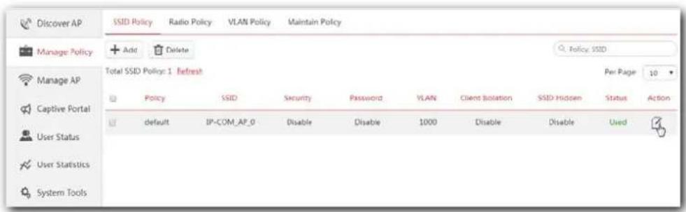
(2) SSID, Security and Key: Set an SSID (WiFi name), security, key (WiFi password) for your AP, and click Save to apply the settings.
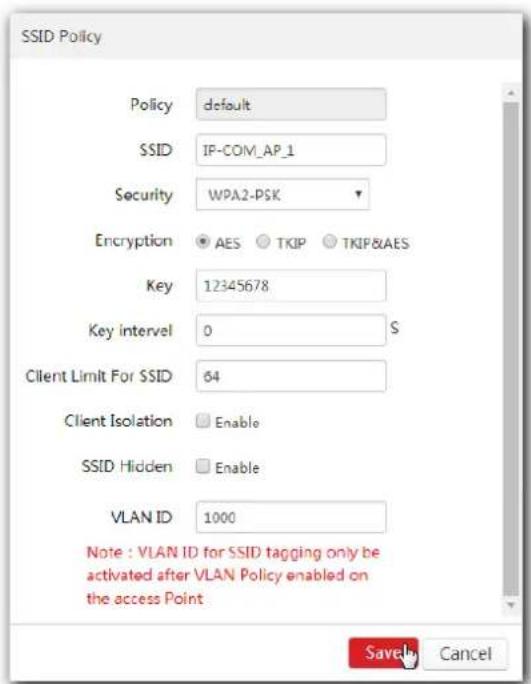
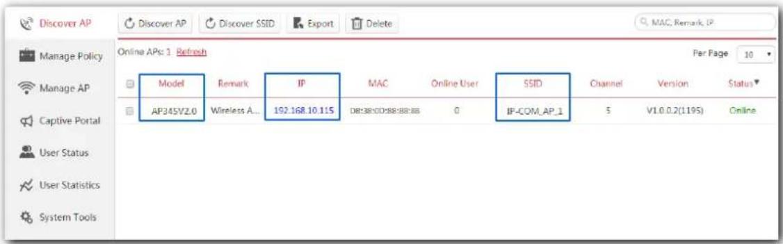
Wait a minute. The AP will obtain the WiFi settings from the AC automatically. You can view your AP's new SSID and IP address on the Discover AP page.
- Connect your wireless devices like smart phones to the WiFi network of your AP using the WiFi name and password you set in step 4.
---End
2.4 Deploying the AP with an IP-COM router with AP control function
A hotel may be deployed with a large number of APs. But you can manage them centrally using an IP-COM router with AP control function. The following describes the procedure.
- Connect devices.
(1) Ensure that your IP-COM router is connected to the internet.
(2) Ensure that your router and PoE switch are connected to power supply.
(3) Connect your computer and PoE switch to the LAN ports of the router using Ethernet cables.
(4) Connect your APs to PoE ports of your PoE switch using Ethernet cables.
The network topology is shown as follows:
flowchart
graph TD
    A["Internet"] --> B["IP-COM router"]
    B --> C["PoE switch"]
    C --> D["AP 1"]
    C --> E["AP 2"]
    C --> F["AP 3"]
    C --> G["AP n"]
    B --> H["PC (For AP management)"]

Note
If you choose to power on your AP using DC power supply, connect the PWR port of your AP to a DC power resource using the included power adapter.
After finishing connection, ensure that the AP's LED indicator blinks and the
lower-right network icon on your computer is not displayed

- Start a web browser on your computer and log in to the web UI of the router. For details about managing your APs, refer to your router's user guide.
---End
3 Login
3.1 Logging in to the web UI of the AP
If you want to log in to the web UI of your AP, perform the following procedures:
- Connect your management computer to the AP' WiFi network or the PoE switch connected to the AP using an Ethernet cable.
- Set IP address of your computer to 192.168.0.x (x: 2 - 253) and subnet mask to 255.255.255.0.

Note
If your AP is managed by an IP-COM AC/router, the AP's IP address may have been changed. In that case, go to the web UI of the router/AC to view the new IP address of the AP, set the IP address of your computer in the same network segment as the AP's new IP address, then log in to the AP's web UI using the new IP address.
-
Start a web browser on the computer, enter the IP address of the AP (default: 192.168.0.254) in the address bar, and press Enter.
-
Enter the user name and password of the AP (default user name and password: admin/admin) and press Login.

Note
If your AP's login page does not appear, refer to Q1 in A.2 FAQ.
---End
Log in to the web UI of the AP successfully. See the following figure:
3.2 Logging out of the web UI of the AP
When you close the web browser, the system logs you out automatically, or if you log in to the web UI of the AP but perform no operation within the login timeout interval, the AP logs you out as well. The default login timeout interval of the AP is 5 minutes, and you can change it on the page Tools > Date & Time > Login Timeout Interval.
3.3 Web UI layout
The web UI of the AP is composed of four parts, including the navigation trees of two levels, tab page area, and configuration area. See the following figure.
| No. | Name | Description |
| 1 | Level-1 navigation bar | The navigation bars and tab pages display the function menu of the AP. When you select a function in the navigation bar, the corresponding configuration appears in the configuration area. |
| 2 | Level-2 navigation bar | |
| 3 | Tab page area | |
| 4 | Configuration area | In this area, you can view and modify configuration of the AP. |

Tip
The functions and parameters dimmed on the web UI indicates that they cannot be changed in the current configuration or they are not supported by the AP. If you want to configure the functions or parameters dimmed on the web UI, you need to configure their related functions or parameters on the web UI first.
3.4 Common buttons
The following table describes the common buttons available on the web UI of the AP.
| Button Description | |
| Save | Click it to save the configuration on the current page and enable the configuration to take effect. |
| Restore | Click it to set the configuration on the current page back to the original configuration. |
| Help | Click it to view corresponding help information on the page. |
4 Status
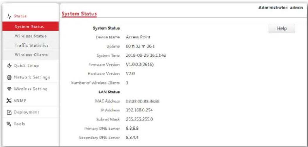
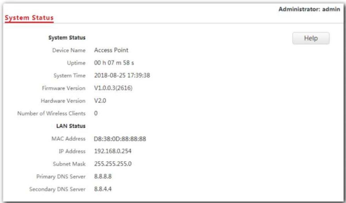
4.1 System status
This page displays the system status and LAN port status of the AP. To access the page, click Status > System Status.
Parameter description
| Parameter Description | |
| Device Name | It specifies the name of the AP. You can change the AP's name on Network Settings > LAN Setup page. |
| Uptime It specifies the time that has elapsed since the AP starts up this time. | |
| System Time It specifies the current system time of the AP. | |
| Firmware Version | It specifies the current firmware version number of the AP. If you have upgraded the firmware version of the AP, view the current firmware version here to check whether the upgrade is successful. |
| Hardware Version | It specifies the current hardware version number of the AP. |
| Number of Wireless Clients | It specifies the number of wireless devices connected to the AP currently. |
| MAC Address | It specifies the physical address of the AP's LAN port. If you connect the AP to other devices using Ethernet cables, the AP uses this MAC address to communicate with those devices. |
| IP Address | It specifies the AP's IP address used to log in to its web UI. If you want to change the IP address, access the Network Settings > LAN Setup page and perform according to the on-screen instructions. |
| Subnet Mask It specifies the subnet mask of the AP's IP address. | |
| Primary DNS Server | It specifies the primary DNS server of the AP. |
| Secondary DNS Server | It specifies the secondary DNS server of the AP. |
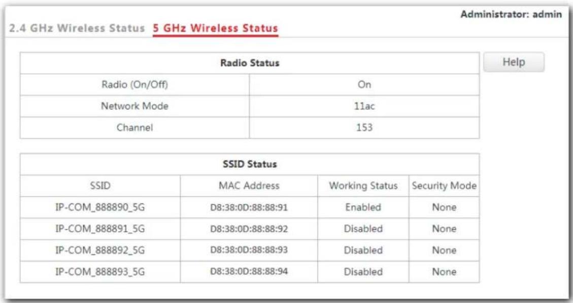
4.2 Wireless status
This page displays radio frequency and SSID status of the AP. To access the page, click Status > Wireless Status.
| Radio Status | |||
| Radio (On/Off) | On | ||
| Network Mode | 11b/g/n | ||
| Channel | 7 | ||
| SSID Status | |||
| SSID | MAC Address | Working Status | Security Mode |
| IP-COM_888888 | D8:38:0D:88:88:89 | Enabled | None |
| IP-COM_888889 | D8:38:0D:88:88:8A | Disabled | None |
| IP-COM_88888A | D8:38:0D:88:88:8B | Disabled | None |
| IP-COM_88888B | D8:38:0D:88:88:8C | Disabled | None |
| IP-COM_88888C | D8:38:0D:88:88:8D | Disabled | None |
| IP-COM_88888D | D8:38:0D:88:88:8E | Disabled | None |
| IP-COM_88888E | D8:38:0D:88:88:8F | Disabled | None |
| IP-COM_88888F | D8:38:0D:88:88:90 | Disabled | None |
Parameter description
| Parameter Description | ||
| Radio Status | Radio (On/Off) | It specifies whether the WiFi network at the corresponding band is enabled. - On: It represents the WiFi network at the corresponding band is enabled. - Off: It represents the WiFi network at the corresponding band is disabled. You can change the radio status on the Wireless Settings > Radio Settings page. |
| Network Mode | It specifies the current network mode of the AP over the 2.4/5 GHz band. You can change the network mode on the Wireless Settings > Radio Settings page. | |
| Channel | It specifies the current working channel of the AP over the 2.4/5 GHz band. You can change the working channel on the Wireless Settings > Radio Settings page. | |
| SSID Status | SSID | It specifies the names of WiFi networks of the AP over the 2.4/5 GHz band. The AP supports eight WiFi networks over 2.4 GHz band and four over 5 GHz band. The first SSID in the SSID status table is the primary SSID of each band. By default, the WiFi network corresponding to the primary SSID is enabled, and the other WiFi networks are disabled. |
| MAC Address | It specifies the physical address of the corresponding SSID. | |
| Working Status | It specifies whether the corresponding WiFi network is enabled. | |
| Security Mode | It specifies the security mode of the corresponding WiFi network. | |
4.3 Traffic statistics
To access the page, click Status > Traffic Statistics.
This page displays statistics about historical packets of AP's WiFi network.
| SSID | Received Traffic | Received Packets | Transmitted Traffic | Transmitted Packets | Help |
| IP-COM_888888 | 3.12MB | 12937 | 0.01MB | 80 | Refresh |
| IP-COM_888889 | 0.00MB | 0 | 0.00MB | 0 | |
| IP-COM_88888A | 0.00MB | 0 | 0.00MB | 0 | |
| IP-COM_88888B | 0.00MB | 0 | 0.00MB | 0 | |
| IP-COM_88888C | 0.00MB | 0 | 0.00MB | 0 | |
| IP-COM_88888D | 0.00MB | 0 | 0.00MB | 0 | |
| IP-COM_88888E | 0.00MB | 0 | 0.00MB | 0 | |
| IP-COM_88888F | 0.00MB | 0 | 0.00MB | 0 |
4.4 Wireless clients
This page displays information about the wireless devices connected to AP's WiFi networks. To access the page, click Status > Wireless Clients.
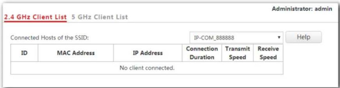
By default, this page displays information about the wireless devices connected to the primary WiFi network of each band. To view information about the wireless devices connected to the other WiFi networks, select the SSIDs from the drop-down list box.
5 Working Mode
5.1 Overview
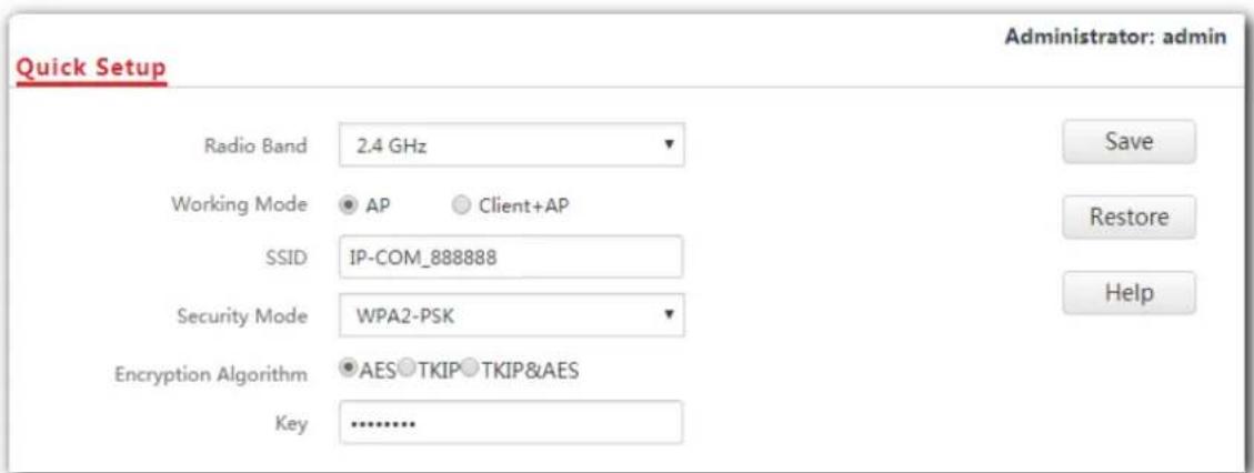
This chapter is mainly about your AP's working mode: AP and Client+AP. To access the configuration page, click Quick Setup. See the following figure.
Parameter description
| Parameter Description | |
| Working Mode | It specifies the working mode you set for your AP, including AP mode and Client+AP mode. |
| SSID | It specifies the SSID (WiFi name) you set for your AP. |
| Security Mode | It specifies the security mode you set for your AP's WiFi network, including None, WEP, WPA-PSK, WPA2-PSK, Mixed WPA/WPA2-PSK, WPA and WPA2. |
| Key | It specifies the WiFi password you set for your AP's WiFi network. |
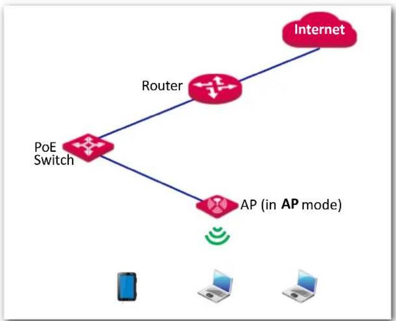
AP mode
By default, the AP works in AP mode. In this mode, the AP connects to an upstream device (such as a router or PoE switch) using an Ethernet cable and converts wired signal into wireless one to offer WiFi coverage. See the following topology.
flowchart
graph TD
    A["PoE Switch"] --> B["Router"]
    A --> C["AP (in AP mode)"]
    D["Internet"] --> B
    E["Mobile Device"] --> F["Laptop"]
    G["Desktop Computer"] --> H["Laptop"]
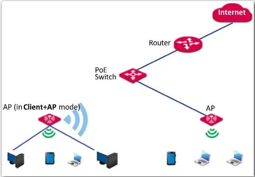
Client+AP mode
In this mode, the AP is wirelessly bridged to an upstream device (such as a wireless router or AP) to extend the WiFi coverage of the upstream device. See the following topology.
flowchart
graph TD
    A["Internet"] --> B["Router"]
    B --> C["PoE Switch"]
    C --> D["AP (in Client+AP mode)"]
    D --> E["Desktop"]
    D --> F["Laptop"]
    D --> G["Laptop"]
    D --> H["Laptop"]
    C --> I["Router"]
    I --> J["AP"]
    J --> K["Laptop"]
    J --> L["Laptop"]
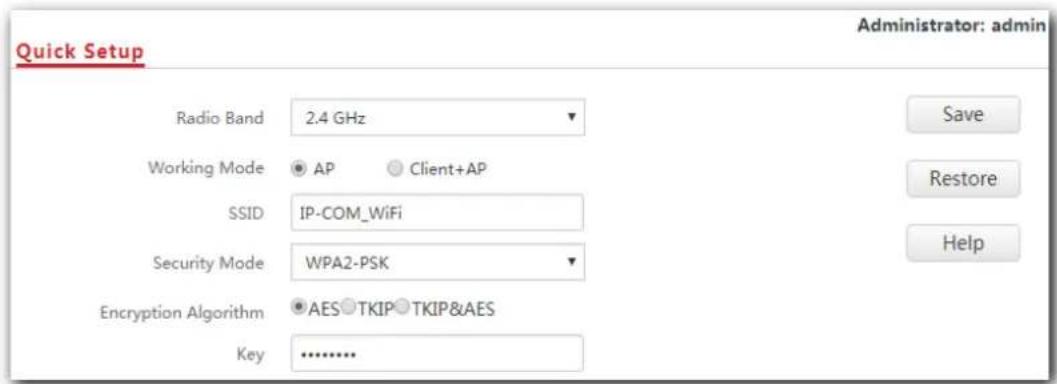
5.2 Setting WiFi network in AP mode
- Click Quick Setup.
- Radio Band: Select the radio band according to your requirement, which is 2.4 GHz in this example.
- Working Mode: Select AP mode.
- SSID: Set a WiFi name for the WiFi network of your AP, which is IP-COM_WiFi in this example.
- Security Mode: Select one security mode for your AP. You are recommended to select WPA2-PSK.
- Encryption Algorithm: Select one encryption algorithm for your AP, which is AES in this example.
- Key: Set a WiFi password for your AP's WiFi network.
- Click Save.
---End
After configuration, connect wireless devices to the WiFi network of your AP using the SSID and WiFi password you set on the Quick Setup page.
5.3 Setting WiFi network in Client+AP mode
- Click Quick Setup.
- Radio Band: Select the radio band according to your requirement, which is 2.4 GHz in this example.
- Working Mode: Click Client+AP mode.
- Click Scan.
- Select the WiFi network you want to extend from the WiFi network list that appears, which is Tom-WiFi in this example.

Note
- If no WiFi network is found, click Wireless Settings > Radio Settings to ensure that Enable Wireless is selected, and try scanning again.
- After a WiFi network is selected, the AP identifies its SSID, security mode, encryption algorithm, channel of WiFi network and populates them automatically. However, some other parameters such as Key must be entered yourself.
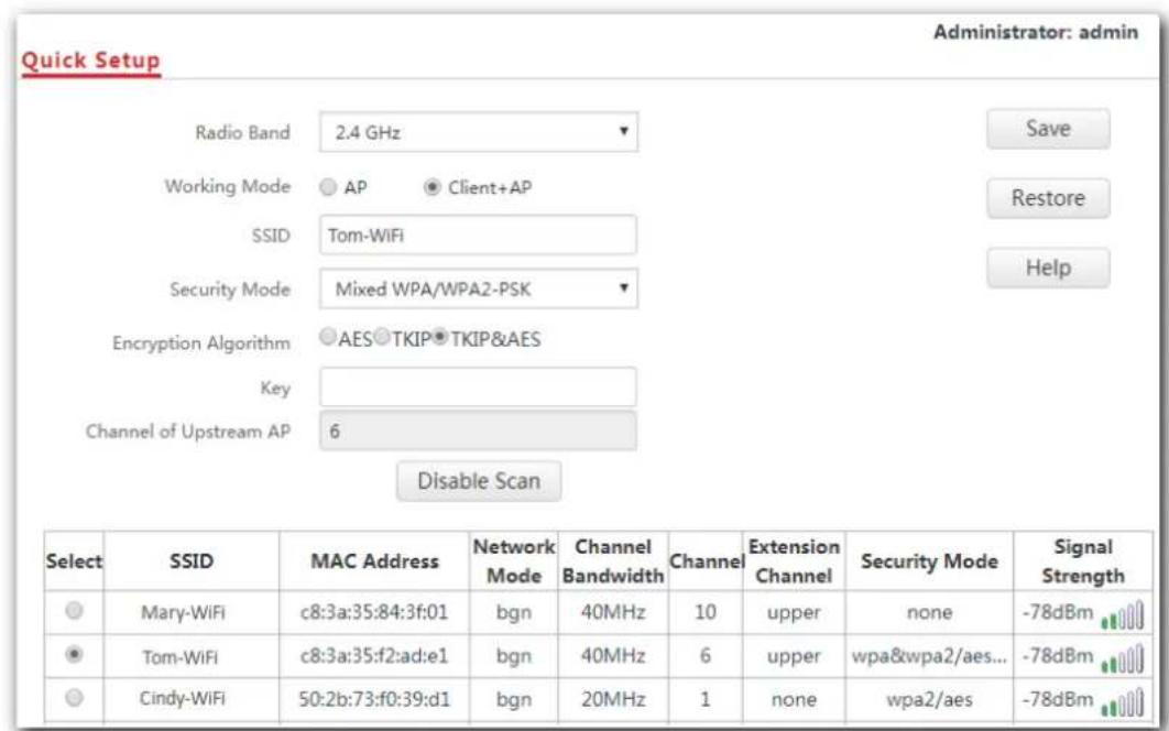
- If the WiFi network of the upstream device is encrypted, enter the WiFi password of the upstream device's in the Key box. Click Save.
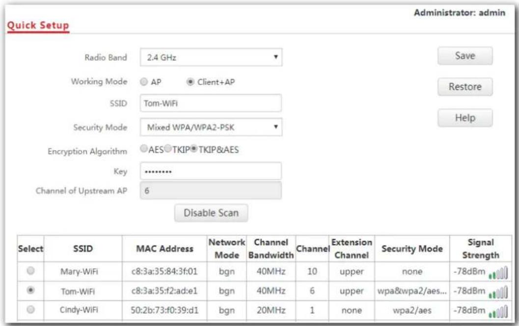
---End
After the configuration, your computer connected to the AP can access the internet directly. And you can also connect wireless devices to the AP's WiFi network using the AP's own SSID and WiFi password. If you do not know the SSID of the AP, click Wireless Settings > SSID Settings.
6 Network Settings
6.1 LAN setup
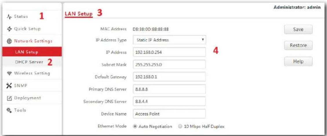
This page enables you to check the MAC address of your AP's LAN port, and set the LAN port's IP address type and other parameters. To access the page, click Network Settings > LAN Setup.
Parameter description
Parameter Description
MAC Address It specifies the MAC address of the AP's LAN port.
| IP Address Type | It specifies how the AP gets its IP address. The default option is Static IP Address. |
| Static IP Address: It indicates that the AP has static IP address information. In this condition, you need to set IP address, subnet mask, gateway, and DNS server information for the AP manually.DHCP: It indicates that the AP gets IP address, subnet mask, gateway, and DNS server information from a DHCP server in your LAN network automatically. |
Parameter Description

| If IP Address Type is set to DHCP, you should log in to the web UI of the AP using the AP's IP address assigned by the DHCP server. To get the AP's IP address, find it in the client list of the DHCP server. | |
| IP Address | It specifies the IP address of the AP (default: 192.168.0.254). You can access the web UI of the AP using this IP address. |
| Subnet Mask | It specifies the subnet mask of the IP address of the AP. The default subnet mask is 255.255.255.0. |
| Default Gateway | It specifies the gateway IP address of the AP.Generally, to ensure that the AP can access the internet successfully, you should set the gateway IP address to the LAN IP address of the router connected to the internet. |
| Primary DNS Server | It specifies the IP address of the primary DNS server of the AP.If DNS proxy function is supported on your router connected to the internet, you can set the IP address of the primary DNS server to the LAN IP address of your router. Otherwise, enter a correct DNS server IP address. |
| Secondary DNS Server | It specifies the IP address of the secondary DNS server of the AP. This parameter is optional. |
Device Name It specifies the name of the AP.
- Auto Negotiation: In this mode, this device can be powered through the LAN port using a CAT 5e or better Ethernet cable with a maximum transmission distance of 100 meters.
- 10 Mbps Half Duplex: In this mode, this device can be powered through the LAN port using a CAT 5e or better Ethernet cable with a maximum transmission distance of 150 to 200 meters.
6.2 Changing the LAN IP address of the AP
6.2.1 Dynamic IP address
This IP address type enables your AP to obtain an IP address, a subnet mask, a gateway IP address, DNS server IP addresses from a DHCP server automatically. If a large number of APs are deployed, you are recommended to adopt this type to prevent IP address conflicts and reduce your workload.
Procedure:
- To access the configuration page, click Network Settings > LAN Setup.
- Set IP Address Type to DHCP.
- Click Save.
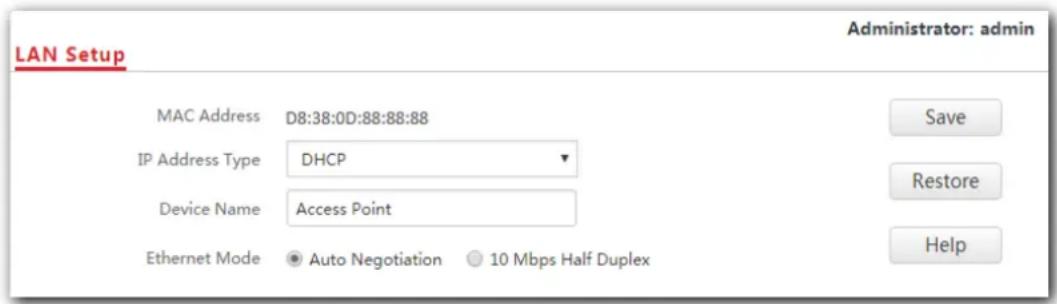
---End
After the configuration, if you want to log in to the web UI of your AP, first find the IP address of the AP from the client list of the DHCP server, then ensure that the IP address of your computer and the IP address of the AP belong to the same network segment, finally log in to the web UI of your AP using its new IP address.

Note
If the IP address of your computer is not in the same network segment as the new IP address of your AP, please set an IP address for your computer which is in the same network segment as the AP's new IP address. For detailed steps to set an IP address for your computer, refer to A.1 Configuring a static IP address for your computer (Example: Win7) in this user guide.
6.2.2 Static IP address
If you want to set AP's IP address yourself, set IP Address Type to Static IP Address first, then configure IP address, subnet mask, gateway IP address, and DNS server IP addresses for your AP manually. This type is recommended only when you need to deploy just a few APs.
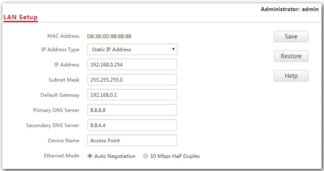
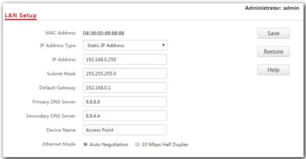
Procedure:
- To access the configuration page, click Network Settings > LAN Setup.
- Set IP Address Type to Static IP Address.
- IP Address: Enter the static IP address for your AP, which is 192.168.0.250 in this example.
- Subnet Mask: Enter the subnet mask for your AP, which is 255.255.255.0 in this example.
- Gateway: Enter the gateway for your AP, which is 192.168.0.1 in this example.
- Primary DNS Server: Enter the primary DNS server for your AP, which is 8.8.8.8 in this example.
- Secondary DNS Server: If this parameter is available, enter the secondary DNS server for your AP, which is 8.8.4.4 in this example. Otherwise, leave this box blank.
- Click Save.
---End
After the configuration, if the new IP address of the AP belongs to the same network segment as the IP address of your management computer, you can log in to the web UI of the AP directly using the new IP address. Otherwise, before logging in to the AP's web UI using the new IP address, assign your computer an IP address that belongs to the same network segment as the new IP address.
6.3 DHCP server
6.3.1 Overview
The AP supports the DHCP server function to assign IP addresses to devices connected to it. By default, this function is disabled.
6.3.2 Configuring the DHCP server
- To access the configuration page, choose Network Settings > DHCP Server.
- DHCP Server: Select Enable.
- Gateway Address: Enter the gateway address, which is 192.168.0.1 in this example.
- Primary DNS Server: Enter the primary DNS server, which is 8.8.8.8 in this example.
- Click Save.
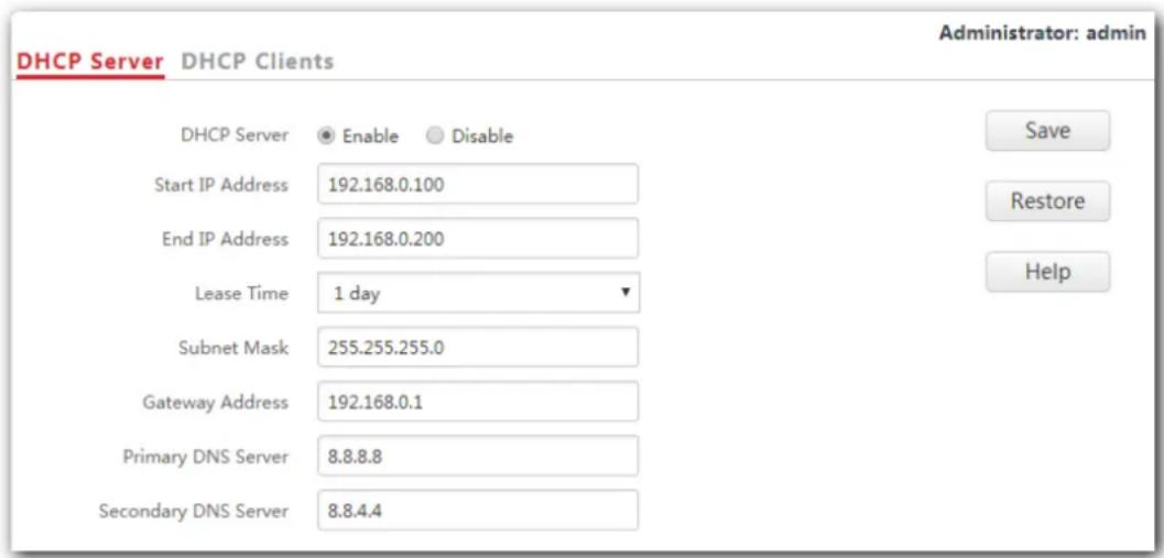
---End
Parameter description
| Parameter Description | |
| DHCP Server | It specifies whether to enable the DHCP server function of the AP. By default, it is disabled. |
| Start IP Address | It specifies the start IP address of the DHCP server's IP address pool. The default value is 192.168.0.100. |
| End IP Address | It specifies the end IP address of the DHCP server's IP address pool. The default value is 192.168.0.200. |
Parameter Description
 The start and end IP addresses must belong to the same network segment as the IP address of the AP. The start and end IP addresses must belong to the same network segment as the IP address of the AP. | |
| Lease Time | It specifies the validity period of an IP address assigned by the DHCP server to a device. By default, it is 1 day.When half of the lease time has elapsed, the device sends a DHCP request to the DHCP server to renew the lease time. If the request succeeds, the lease time is extended based on the request. Otherwise, the device sends a request again when 7/8 of the lease time has elapsed. If the request succeeds, the lease time is extended based on the request. Otherwise, the device must request a new IP address from the DHCP server after the lease time expires.You are recommended to retain the default value. |
| Subnet Mask | It specifies the subnet mask assigned by the DHCP server to devices. The default value is 255.255.255.0. |
| Gateway Address | It specifies the gateway IP address assigned by the DHCP server to devices. Generally, it is the LAN IP address of the router connected to the internet. The default value is 192.168.0.1.Only through a gateway can a LAN device access a server or host which is not in the local network segment. You are recommended to enter a gateway IP address which can access the internet. Otherwise, the device in the LAN network cannot access the internet. |
| Primary DNS Server | It specifies the DNS server address provided by your ISP. If you do not know it, please consult your ISP. |
| To enable devices to access the internet, set this parameter to a correct DNS server IP address or DNS proxy IP address. | |
| Secondary DNS Server | It specifies the second DNS server address (if any) provided by your ISP. This parameter is optional, which indicates you can leave it blank if your ISP does not provide this parameter. |

Note
If another DHCP server is available in your LAN, ensure that the IP address pool of the AP does not overlap the IP address pool of that DHCP server. Otherwise, IP address conflicts may occur.
6.3.3 DHCP clients
If the AP's DHCP server function is enabled, this module enables you to view detailed information about devices that obtain IP addresses from the AP's DHCP server, which includes host names, IP addresses, MAC addresses, and lease time.
To access the page, choose Network Settings > DHCP Server > DHCP Clients.
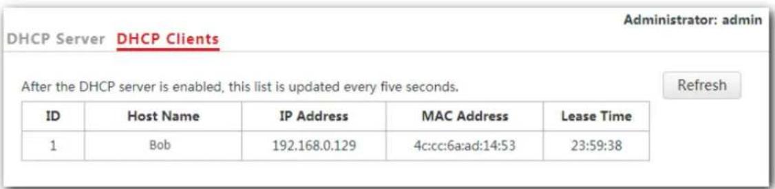
You can click Refresh to view the latest DHCP client list.
7 Wireless Settings
7.1 SSID settings
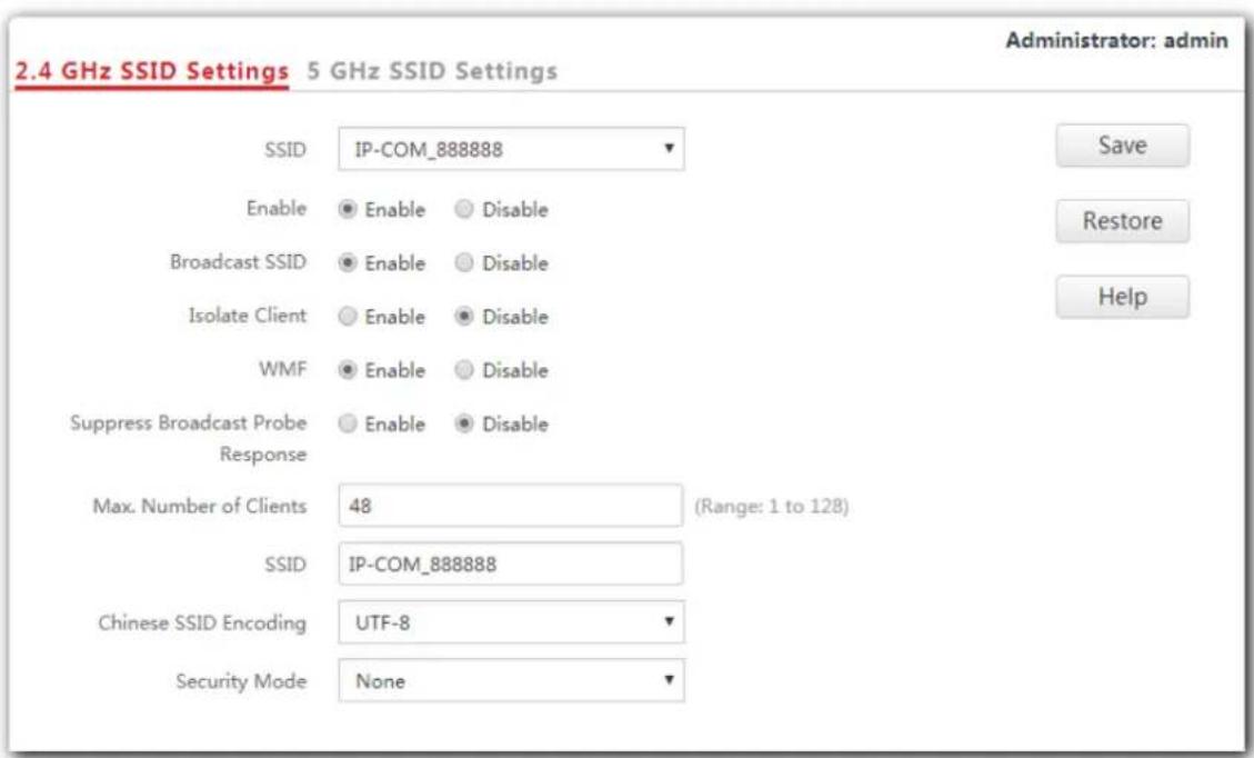
7.1.1 Overview
This module enables you to set SSID-related parameters of the AP. To access the configuration page, click Wireless Settings > SSID Settings.
Broadcast SSID
When the AP broadcasts an SSID, wireless devices nearby can detect the SSID. When this parameter is set to Disable, the AP does not broadcast the SSID so that nearby wireless devices cannot detect the SSID. In this case, you need to enter the SSID manually on your wireless devices to connect to the WiFi network corresponding to the SSID. To some extent, disabling broadcasting SSID enhances the security of the WiFi network.
However, even though setting Broadcast SSID to Disable, a hacker can still connect to the
corresponding WiFi network if he/she manages to obtain the SSID by other means.
Isolate Client
This parameter implements a function similar to the VLAN function for wired networks. It isolates the wireless devices connected to the same WiFi network, so that the wireless devices can access only the wired network connected to the AP. You can apply this function to hotspot setup in public such as hotels and airports to improve network security.
WMF
The number of wireless devices keeps increasing currently, but wired and wireless bandwidth resources are limited. Therefore, the multicast technology, which enables single-point data transmission and multi-point data reception, has been widely used in networks in order to reduce bandwidth requirements and prevent network congestion.
Nevertheless, if a large number of devices are connected to a wireless interface of a WiFi network and multicast data is intended for only one of the devices, the data is still sent to all the devices, which increases unnecessary wireless resource usage and may lead to wireless channel congestion. In addition, multicast stream forwarding over an 802.11 network is not secure, either.
The WMF function of the AP converts multicast traffic into unicast traffic and forwards the traffic to the multicast traffic destination in the WiFi network, helping save wireless resources, ensuring reliable transmission, and reducing delays.
Max. Number of Clients
This parameter specifies the maximum number of devices that can connect to the WiFi network corresponding to an SSID. If the number is reached, the WiFi network rejects new connection requests from devices. This limit helps balance load among APs.
Chinese SSID Encoding
It specifies the encoding format of Chinese SSIDs, which consists of UTF-8 (default) and GB2312. This setting is effective only when an SSID contains Chinese characters. If you want your Chinese SSID to be displayed properly, select the encoding format supported by you wireless devices.
Security Mode
A WiFi network uses radio open to the public as its data transmission medium. If the WiFi network is not protected by necessary measures, any device can connect to the network to access unprotected data over the network or the resources of the network. To ensure communication security, transmission links of WiFi network must be encrypted.
The AP supports various security modes for network encryption, including None, WEP, WPA-PSK, WPA2-PSK, Mixed WPA/WPA2-PSK, WPA, and WPA2.
None
It indicates that any wireless device can connect to the WiFi network. This option is not recommended because it leads to network insecurity.
WEP
It uses a static key to encrypt all exchanged data, and ensures that a WLAN has the same level of security as a wired LAN. However, data encrypted based on WEP can be easily cracked. In addition, WEP supports a maximum WiFi network throughput of only 54 Mbps. Therefore, this security mode is not recommended.
WPA-PSK, WPA2-PSK, and Mixed WPA/WPA2-PSK
They belong to pre-shared key or personal key modes, where Mixed WPA/WPA2-PSK supports both WPA-PSK and WPA2-PSK.
WPA-PSK, WPA2-PSK, and Mixed WPA/WPA2-PSK adopt a pre-shared key for authentication, while the AP generates another key for data encryption. This prevents the vulnerability caused by static WEP keys, and makes the three security modes suitable for ensuring security of home WiFi networks. Nevertheless, because the initial pre-shared key for authentication is manually set and all devices use the same key to connect to the same AP, the key may be disclosed unexpectedly. This makes the security modes not suitable for scenarios where high security is required.
WPA and WPA2
To address the key management weakness of WPA-PSK and WPA2-PSK, the WiFi Alliance puts forward WPA and WPA2, which use 802.1x to authenticate devices and generate data encryption-oriented root keys. WPA and WPA2 use the root keys to replace the pre-shared keys that set manually, but adopt the same encryption process as WPA-PSK and WPA2-PSK.
WPA and WPA2 uses 802.1x to authenticate devices and the login information of a device is managed by the device. This effectively reduces the probability of information leakage. In addition, each time a device connects to an AP that adopts the WPA or WPA2 security mode, the RADIUS server generates a data encryption key and assigns it to the device, which makes it difficult for attackers to obtain the key. These features of WPA and WPA2 security modes help increase network security significantly, making WPA and WPA2 the preferred security modes of WiFi networks that require high security.
7.1.2 Changing the SSID settings
To change the SSID settings, perform the following procedure:
- Choose Wireless Settings > SSID Settings.
- Click a tag page as required, which is 2.4 GHz SSID Settings in this example.
- Select the SSID from the SSID drop-down list box.
- Change the parameters as required. Generally, you only need to set the SSID, and Security Mode, Key parameters.
5. Click Save.
---End
Parameter description
| Parameter Description | |
| SSID | It specifies the SSID to be configured.The AP supports eight SSIDs over the 2.4 GHz band and four over the 5 GHz band. The first SSID displayed in the SSID list of the corresponding band is the primary SSID of that band. |
| Enable | It specifies whether to enable the selected SSID.The primary SSID of each band is enabled by default, while the others are disabled. Users can enable them if required. |
| Broadcast SSID | It specifies whether to broadcast the selected SSID.- Enable: It indicates that the AP broadcasts the selected SSID. In this case, nearby wireless devices can detect the SSID.- Disable: It indicates that the AP does not broadcast the selected SSID so that nearby wireless devices cannot detect the SSID. In this case, if you want to connect a wireless device to the WiFi network corresponding to the SSID, you must enter the SSID on the device manually. |
Parameter Description

| This AP can hide its SSID automatically. When an SSID's connected devices number reaches its max number of clients, the AP stops broadcasting the SSID. | |
| Isolate Client | - Enable: It indicates that the wireless devices connected to the AP with the selected SSID cannot communicate with each other, which improves WiFi network security.- Disable: It indicates that the wireless devices connected to the AP with the selected SSID can communicate with each other. By default, Isolate Client is disabled. |
| WMF | - Enable: It indicates that the WMF function is enabled.- Disable: It indicates that the WMF function is disabled. By default, WMF function is disabled. |
| Suppress Broadcast Probe Response | - Enable: It indicates that the Suppress Broadcast Probe Response function is enabled. After this function is enabled, this device does not respond to the requests without an SSID, saving wireless resources.- Disable: It indicates that the Suppress Broadcast Probe Response function is disabled. By default, the function is disabled. |
| Max. Number of Clients | It specifies the maximum number of devices that can be concurrently connected to the WiFi network corresponding to an SSID.After this upper limit is reached, the AP rejects new requests from devices for connecting to the wireless network. |
| SSID | If you want to change the selected SSID, enter the new SSID in this box. |
| Chinese SSID Encoding | It specifies the encoding format of Chinese characters in an SSID. The default value is UTF-8. This parameter takes effect only if the SSID contains Chinese characters. |
| Security Mode | It specifies the security mode of the selected SSID. The options include: None, WEP, WPA-PSK, WPA2-PSK, Mixed WPA/WPA2-PSK, WPA and WPA2. Refer to following contents for details about these options. |
None
It allows any wireless device to connect to the WiFi network. This option is not recommended because it leads network insecurity.
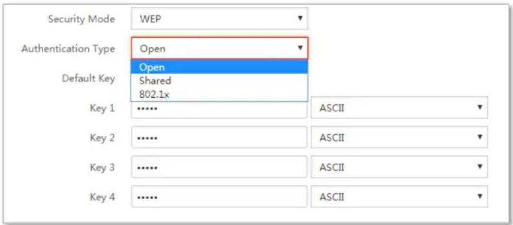
WEP
Parameter description
Parameter Description
| It specifies the encryption type for the WEP security mode of the AP. The options includeOpen, Shared, and802.1x, and they share the same encryption process. | |
| - OpenIt specifies that authentication is not required and data exchanged is encrypted using WEP. In this case, a wireless device can connect to the wireless network corresponding to the selected SSID without being authenticated, and the data exchanged between the device and the network is encrypted in WEP security mode. | |
| Authentication Type | - SharedIt specifies that a shared key is used for authentication and data exchanged is encrypted using WEP. In this case, a wireless device must use a preset WEP key to connect to the wireless network corresponding to the selected SSID. The wireless device can be connected to the wireless network only if they use the same WEP key. |
| - 802.1xIt specifies that 802.1x authentication is required and data exchanged is encrypted using WEP. In this case, ports are enabled for user authentication when valid devices connect to the wireless network corresponding to the selected SSID, and disabled when invalid devices connect to the wireless network. | |
| Default Key | It specifies the default WEP key for theOpenandSharedencryption types.For example, ifDefault Keyis set toKey 2, a wireless device can connect to the wireless network corresponding to the selected SSID only with the password specified byKey 2. |
| Parameter Description | |
| ASCII | It indicates that a key selected for theOpen or Shared authentication type contains hexadecimal characters. 5 or 13 ASCII characters are allowed in the key. |
| Hexadecimal | It indicates that a key selected for theOpen or Shared authentication type contains hexadecimal characters. 10 or 26 hexadecimal characters (range: 0-9, a-f, and A-F) are allowed in the key. |
| RADIUS Server IP | These parameters are dedicated to the 802.1x authentication type. |
| RADIUS Port | It specifies the IP address/port number/shared key of the RADIUS server for authentication. |
| RADIUS Password | |
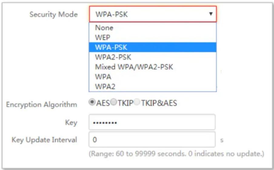
WPA-PSK, WPA2-PSK, and Mixed WPA/WPA2-PSK
Parameter description
Parameter Description
| It indicates the personal or pre-shared key security mode, including WPA-PSK, WPA2-PSK, and Mixed WPA/WPA2-PSK. | |
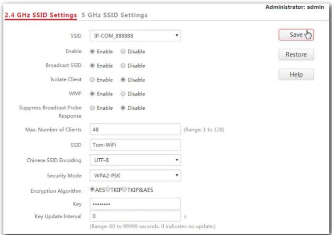
| Security Mode | WPA-PSK: It indicates that the WiFi network corresponding to the selected SSID is encrypted using WPA-PSK.WPA2-PSK: It indicates that the WiFi network corresponding to the selected SSID is encrypted using WPA2-PSK.Mixed WPA/WPA2-PSK: It indicates that wireless devices can connect to the WiFi network corresponding to the selected SSID using either WPA-PSK or WPA2-PSK. |
| Encryption Algorithm | It specifies the encryption algorithm corresponding to the selected security mode. If Security Mode is set to WPA-PSK, this parameter has the AES and TKIP values. If Security Mode is set to WPA2-PSK or Mixed |
Parameter Description
| WPA/WPA2-PSK, this parameter has the AES, TKIP, and TKIP&AES values. - AES: It specifies the Advanced Encryption Standard. - TKIP: It specifies the Temporal Key Integrity Protocol. If TKIP is used, the maximum wireless throughput of the AP is limited to 54 Mbps. - TKIP&AES: It specifies that both the TKIP and AES encryption algorithms are supported. Wireless devices can connect to the WiFi network corresponding to the selected SSID using TKIP or AES. | |
| Key | It specifies a pre-shared WPA key. A WPA key can contain 8 to 63 ASCII characters or 8 to 64 hexadecimal characters. |
| Key Update Interval | It specifies the automatic update interval of a WPA key for data encryption. A shorter interval results in higher data security. The value 0 indicates that a WAP key is not updated. |
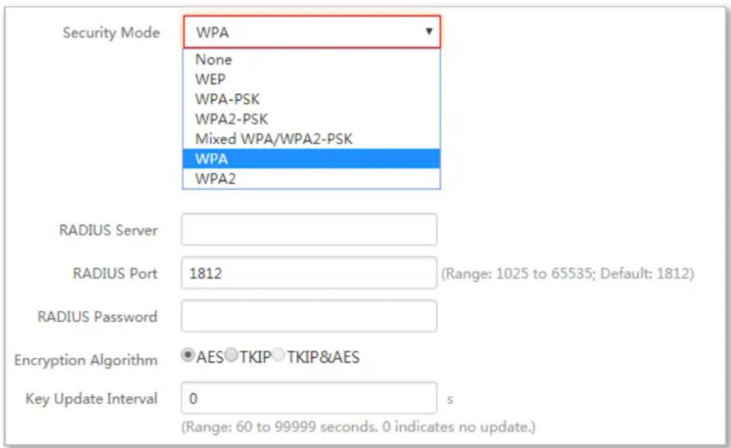
WPA and WPA2
Parameter description
Parameter Description
| The WPA and WPA2 options are available for network protection with a RADIUS server. | |
| Security Mode | WPA: It indicates that the WiFi network corresponding to the selected SSID is encrypted using WPA.WPA2: It indicates that the WiFi network corresponding to the selected SSID is encrypted using WPA2. |
| Parameter Description | |
| RADIUS Server | It specifies the IP address of the RADIUS server for client authentication. |
| RADIUS Port | It specifies the port number of the RADIUS server for client authentication. |
| RADIUS Password | It specifies the shared password of the RADIUS server. |
| Encryption Algorithm | It specifies the encryption algorithm corresponding to the selected security mode. The available options include AES, TKIP, and TKIP&AES.AES: It specifies the Advanced Encryption Standard.TKIP: It specifies the Temporal Key Integrity Protocol.TKIP&AES: It specifies that both the TKIP and AES encryption algorithms are supported. Wireless devices can connect to the WiFi network corresponding to the selected SSID using TKIP or AES. |
| Key Update Interval | It specifies the automatic update interval of a WPA key for data encryption. A shorter interval results in higher data security. The value 0 indicates that a WAP key is not updated. |
7.1.3 Examples
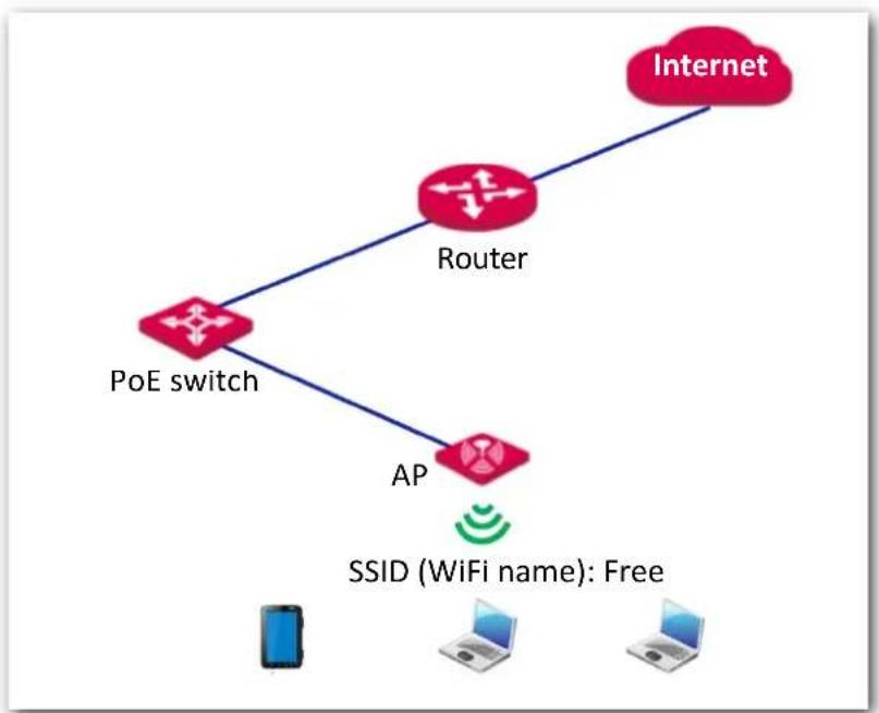
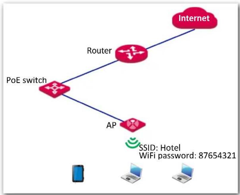
Setting up a non-encrypted WiFi network
Networking requirement
In a hotel, guests can connect to the WiFi network without a password and access the internet through the WiFi network.
flowchart
graph TD
    A["PoE switch"] --> B["Router"]
    A --> C["AP"]
    B --> D["Internet"]
    C --> D
    style A fill:#f9f,stroke:#333
    style D fill:#ccf,stroke:#333
    note bottom of D SSID (WiFi name): Free
Procedures:
- Choose Wireless Settings > SSID Settings.
- If you want to set SSID of 5 GHz WiFi network, click 5 GHz SSID Settings. And 2.4 GHz SSID Settings is used for instructions in this example.
- SSID: Select a SSID from the SSID drop-down list box, which is IP-COM_888889 in this example.
- Enable: Select Enable.
- SSID: Set the value of the SSID box to Free.
- Security Mode: Select None.
- Click Save.
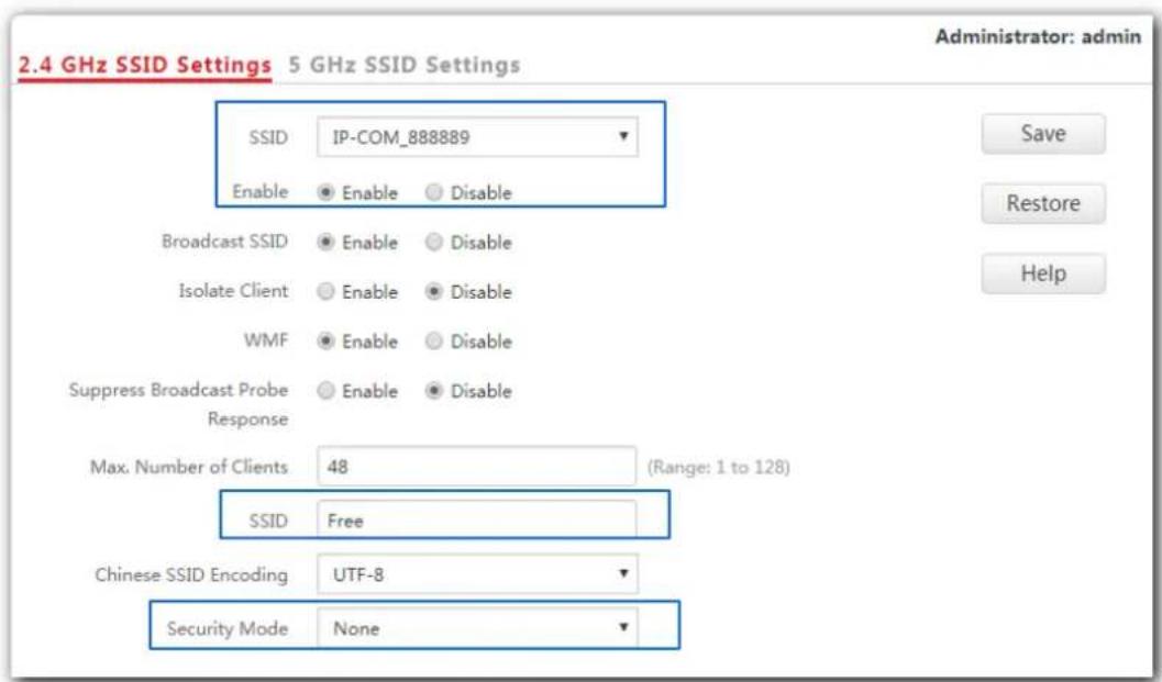
---End
Verification
Wireless devices can connect to the WiFi network named Free without a password.
Setting up a WiFi network encrypted by WPA-PSK or WPA2-PSK
Networking requirement
WiFi network in a hotel with a certain level of security must be configured through a simply procedure. In this case, WPA-PSK or WPA2-PSK mode is recommended. See the following figure.
flowchart
graph TD
    A["PoE switch"] --> B["Router"]
    A --> C["AP"]
    B --> D["Internet"]
    C --> D
    E["Mobile Device"] --> F["WiFi Password: 87654321"]
    G["Computer"] --> H["WiFi Password: 87654321"]
Procedures:
- Choose Wireless Settings > SSID Settings.
- If you want to set SSID of 5 GHz WiFi network, click 5 GHz SSID Settings. And 2.4 GHz SSID Settings is used for instructions in this example.
- SSID: Select a SSID from the SSID drop-down list box, which is IP-COM_888889 in this example.
- Enable: Select Enable.
- SSID: Set the value of the SSID box to Hotel.
- Security Mode: Select WPA2-PSK.
- Encryption Algorithm: Select AES.
- Key: Enter 87654321.
- Click Save.
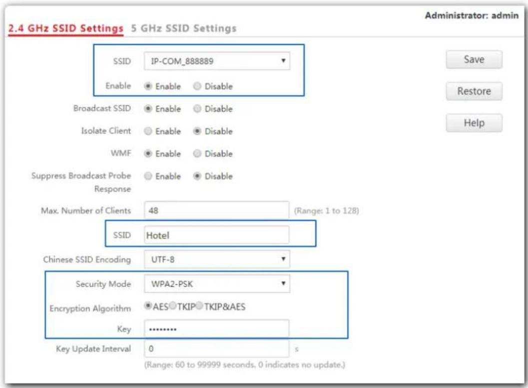
---End
Verification
Wireless devices can connect to the WiFi network named Hotel using the password 87654321.
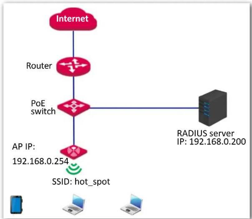
Setting up a WiFi network encrypted by WPA or WPA2
Networking requirement
In this case a highly secure WiFi network is required and a RADIUS server is available. To fulfill the requirement, WPA or WPA2 mode is recommended. See the following figure.
flowchart
graph TD
    A["Internet"] --> B["Router"]
    B --> C["PoE switch"]
    C --> D["RADIUS server"]
    D --> E["AP IP: 192.168.0.254"]
    D --> F["SSID: hot_spot"]
    G["Laptop"] --> H["AP IP: 192.168.0.200"]
Procedures:
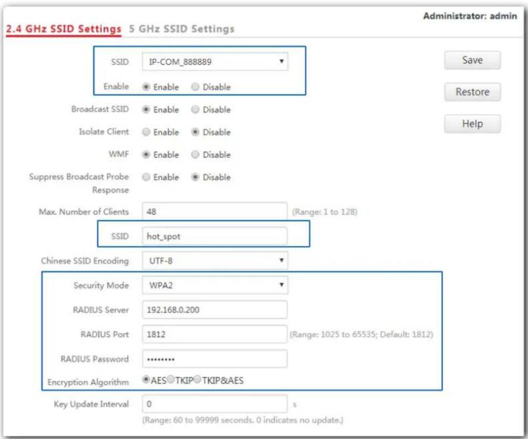
1. Configure the AP.
Assume that the IP address of the RADIUS server is 192.168.0.200, the password is 12345678, and the port number for authentication is 1812.
Assume that the second SSID of the AP is used.
(1) Choose Wireless Settings > SSID Settings.
(2) If you want to set SSID of 5 GHz WiFi network, click 5 GHz SSID Settings. And 2.4 GHz SSID Settings is used for instructions in this example.
(3) Select the second SSID from the SSID drop-down list box.
(4) Enable: Select Enable.
(5) Change the value of the SSID text box to hot_spot.
(6) Set Security Mode to WPA2.
(7) Set RADIUS Server IP, RADIUS Port, and RADIUS Password to 192.168.0.200, 1812, and 12345678 respectively.
(8) Encryption Algorithm: Select AES.
(9) Click Save.
- Configure the RADIUS server.

Note
Windows 2003 is used as an example to describe how to configure the RADIUS server.
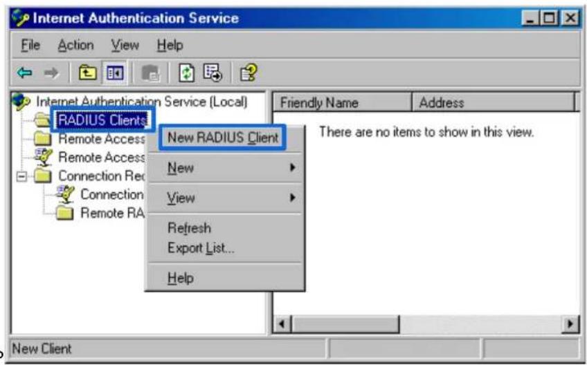
(1) Configure a RADIUS client.
In the Computer Management dialog box, double-click Internet Authentication Service, right-click RADIUS Clients, and choose New RADIUS Client.
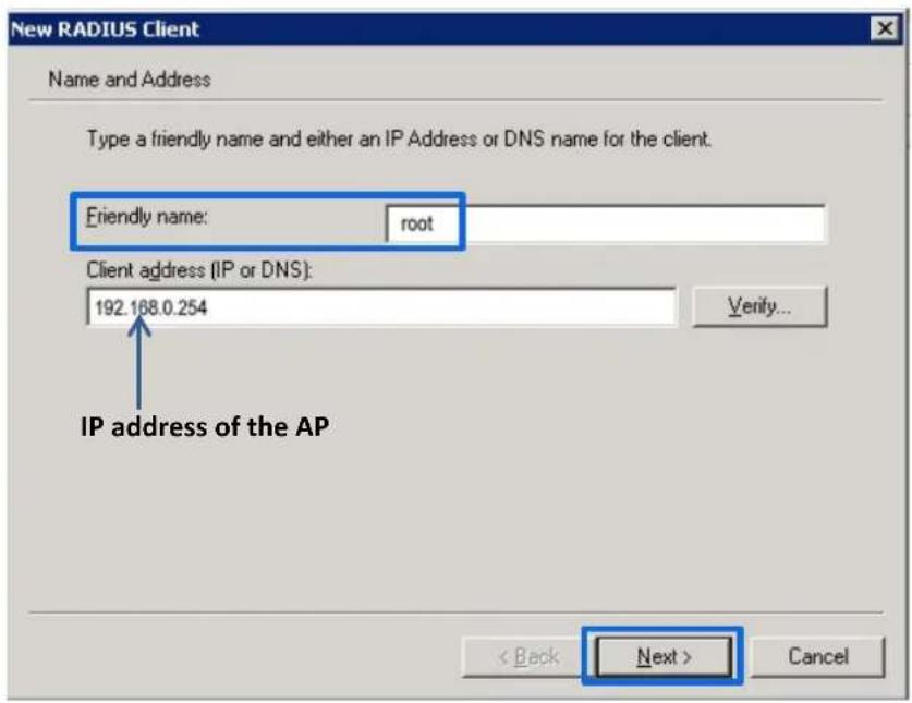
Enter a RADIUS client name (which can be the name of the AP) and the IP address of the AP, and click Next.
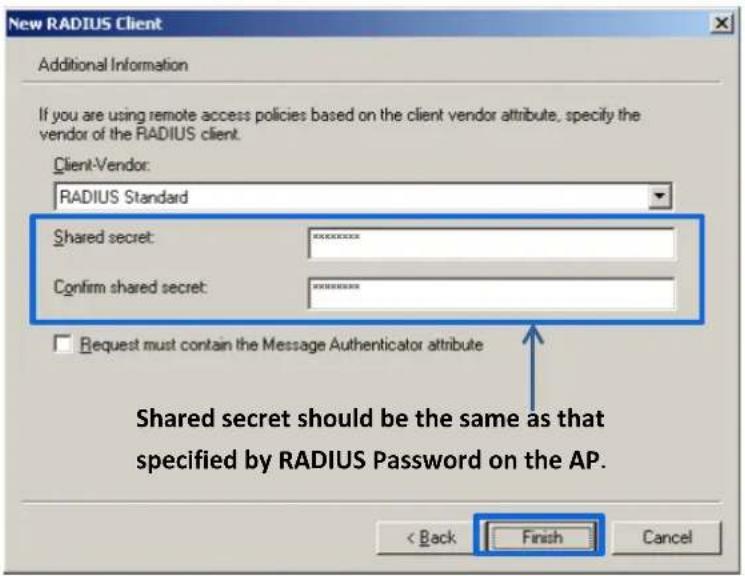
Enter 12345678 in the Shared secret and Confirm shared secret text boxes, and click Finish.
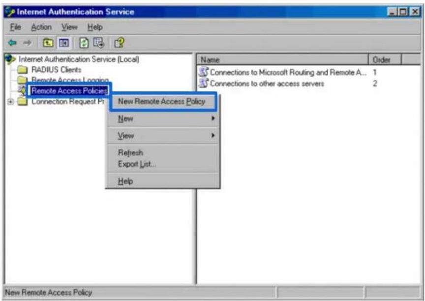
(2) Configure a remote access policy.
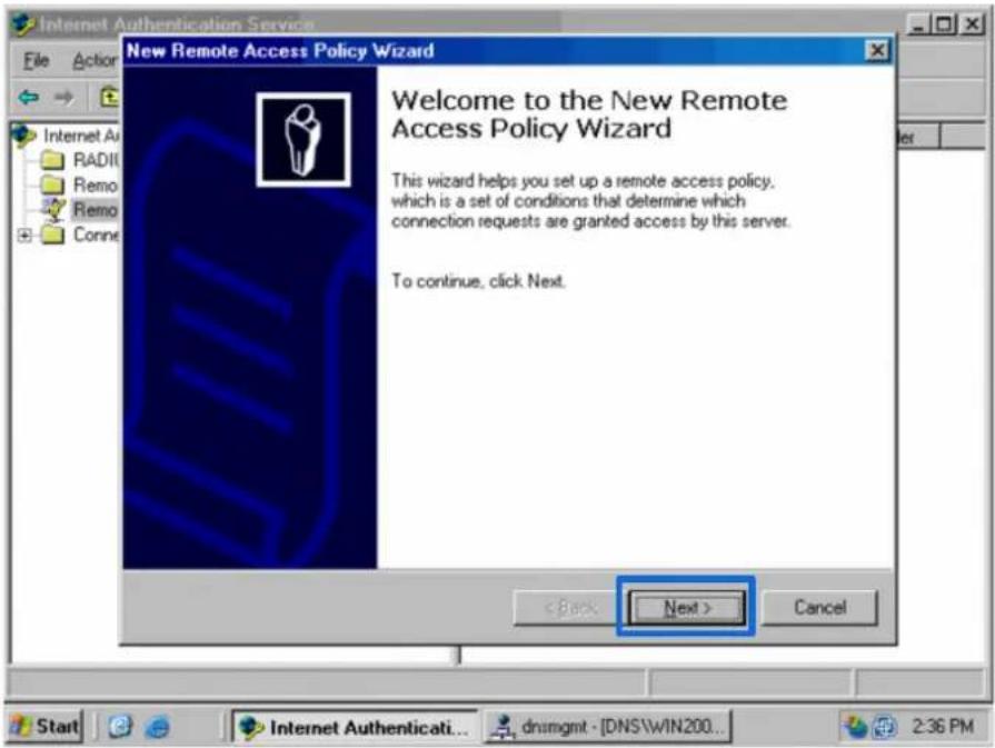
Right-click Remote Access Policies and choose New Remote Access Policy.
In the New Remote Access Policy Wizard dialog box that appears, click Next.
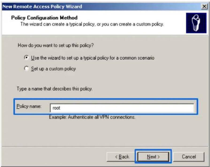
Enter a policy name and click Next.
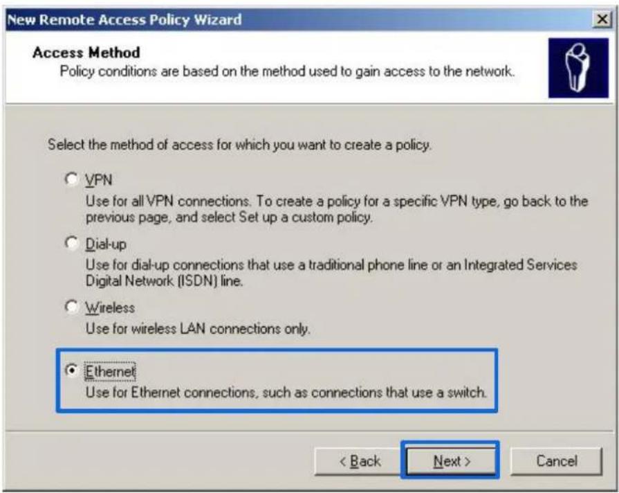
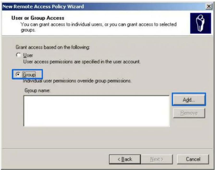
Select Ethernet and click Next.
Select Group and click Add.
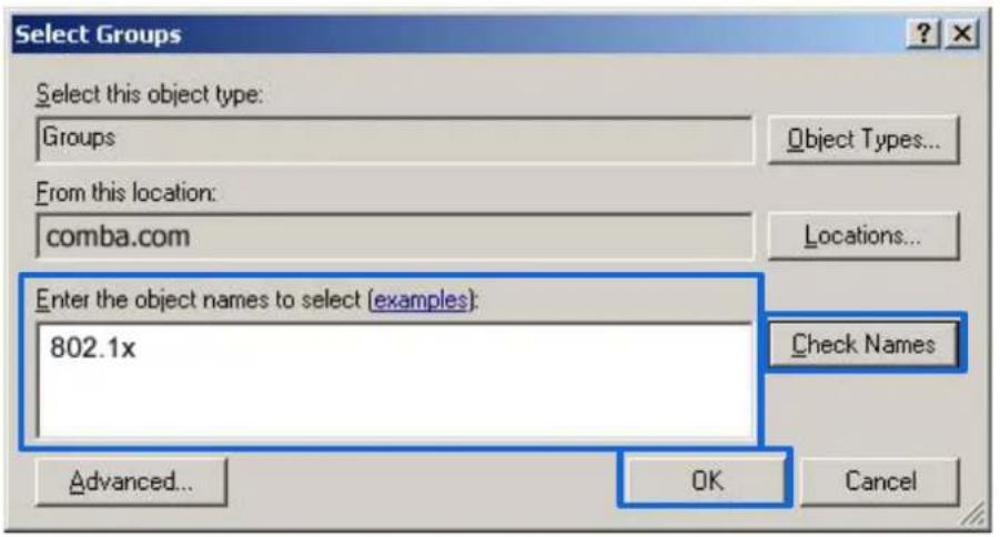
Enter 802.1x in the Enter the object names to select text box, click Check Names, and click OK.
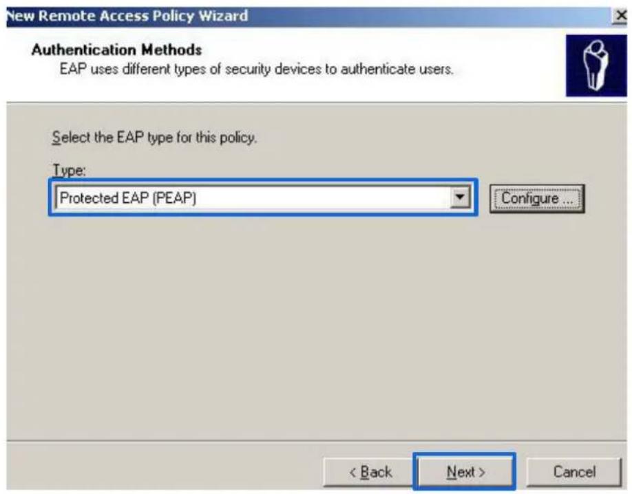
Select Protected EAP (PEAP) and click Next.
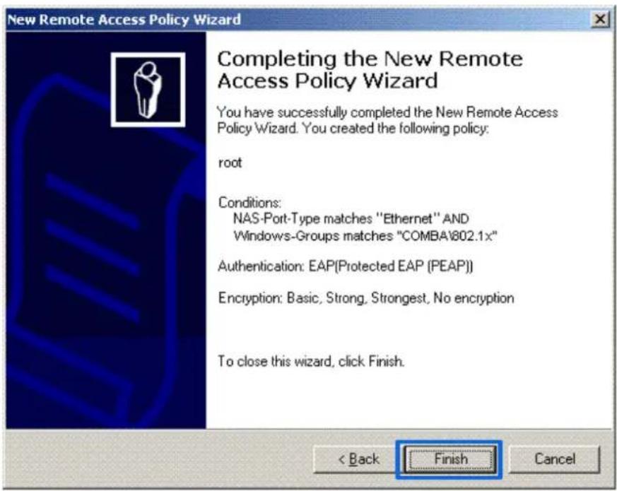
Click Finish. The remote access policy is created.
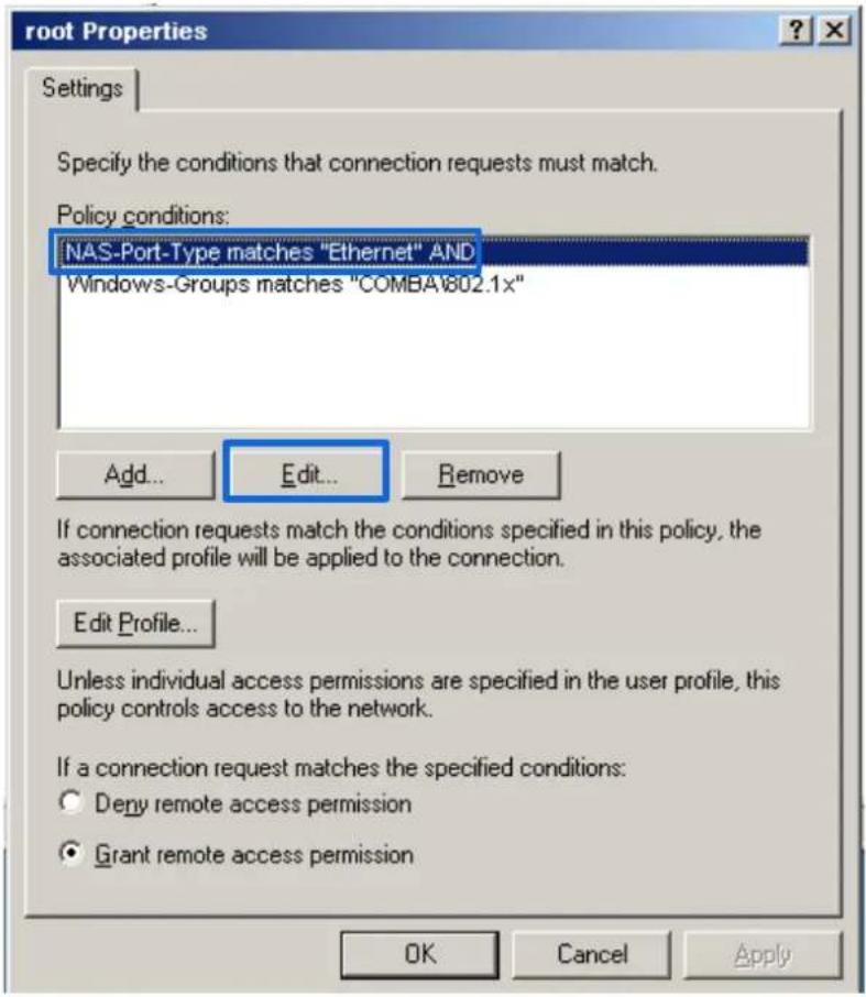
Right-click root and choose Properties. Select Grant remote access permission, select NAS-Port-Type matches "Ethernet" AND, and click Edit.
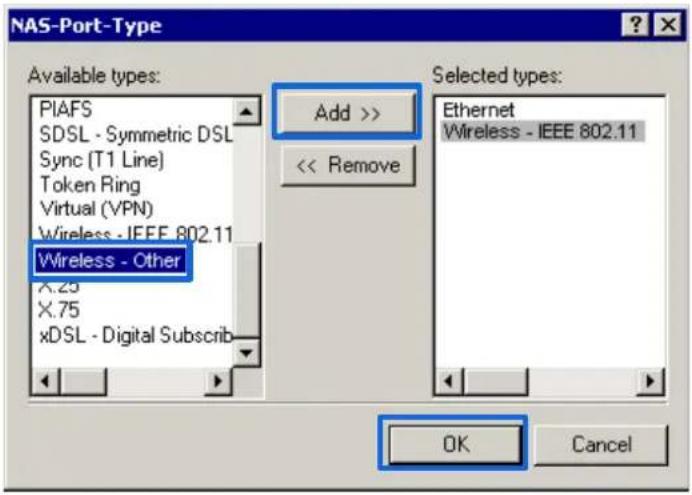
Select Wireless – Other, click Add, and click OK.
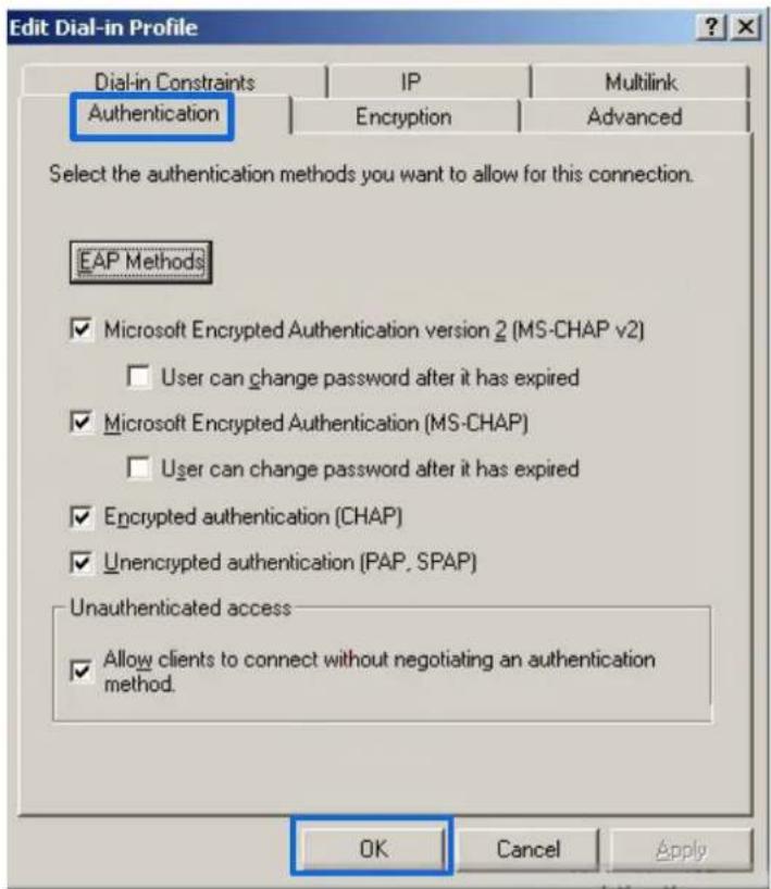
Click Edit Dial-in Profile, click the Authentication tab, configure settings as shown in the following figure, and click OK.
When a message appears, click No.
(3) Configure user information.
Create a user and add the user to group 802.1x.
---End
3. Configure your wireless device.

Tip
Windows 7 is taken as an example to describe the procedure.
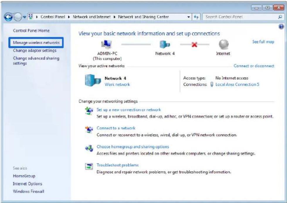
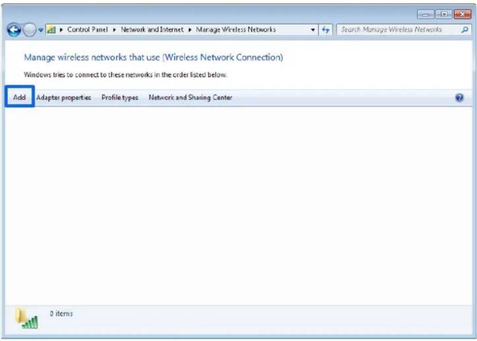
Choose Start > Control Panel, click Network and Internet, click Network and Sharing Center, and click Manage wireless networks.
Click Add.
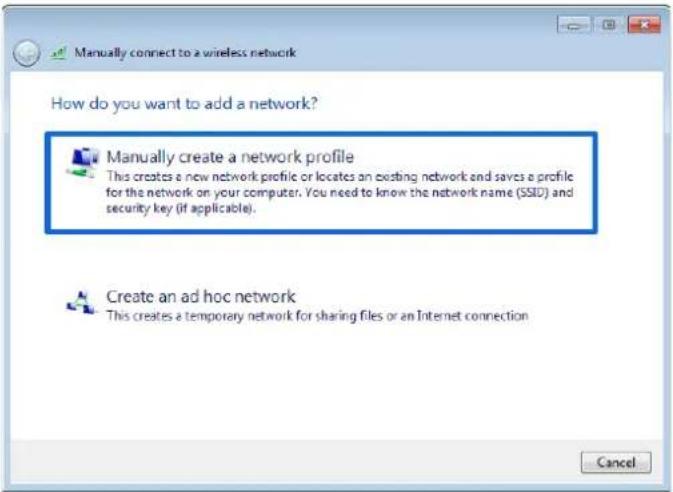
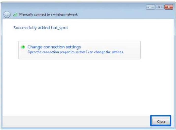
Click Manually create a network profile.
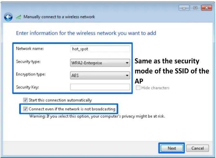
Enter WiFi network information, select Connect even if the network is not broadcasting, and click Next.
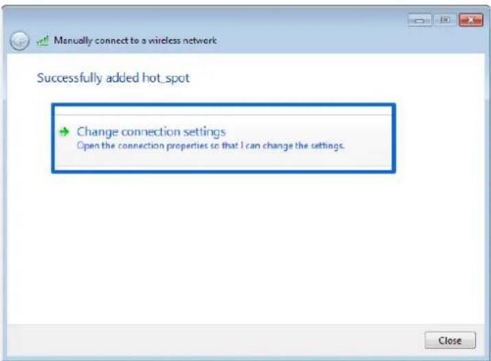
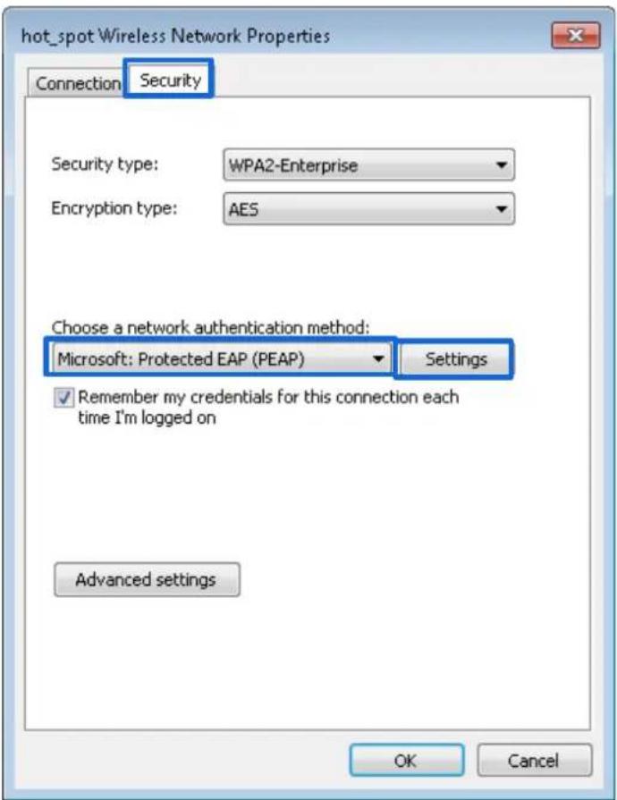
Click Change connection settings.
Click the Security tab, select Microsoft: Protected EAP (PEAP), and click Settings.
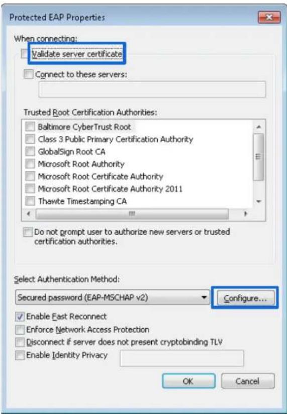
Deselect Validate server certificate and click Configure.
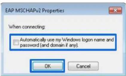
Deselect Automatically use my Windows logon name and password (and domain if any) and click OK.
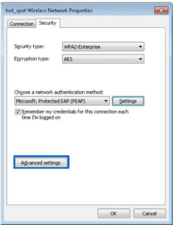
Click Advanced settings.
Select User or computer authentication and click OK.
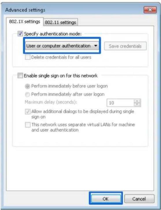
Click Close.
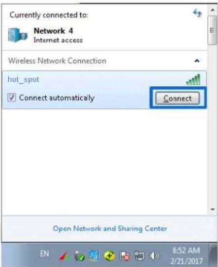
Click the network icon in the lower-right corner of the desktop and choose the WiFi network of the AP, which is hot_spot in this example.
In the Windows Security dialog box that appears, enter the user name and password set on the RADIUS server and click OK.
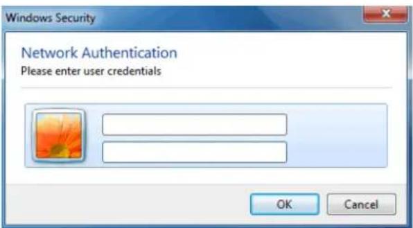
---End
Verification
Wireless devices can connect to the WiFi network named hot_spot.
7.2 Radio settings
7.2.1 Overview
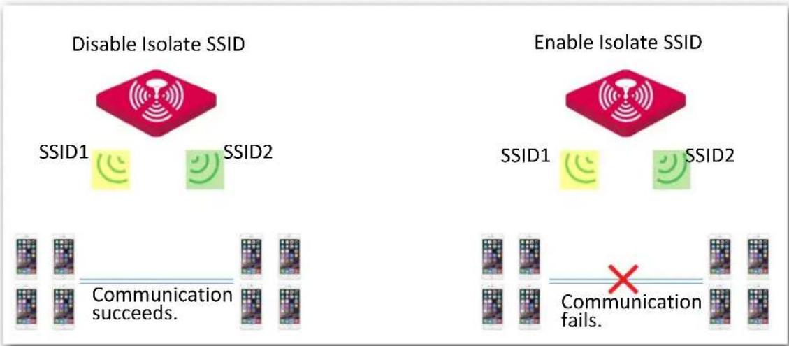
This module is used to set radio parameters of the AP, such as country/region and network mode. It also enables you to turn on/off the Isolate SSID function. The following describes the Isolate SSID function briefly.
Isolate SSID
This function isolates the wireless devices connected to different WiFi networks of the AP. For example, if user A connects to the WiFi network corresponding to SSID1, whereas user B connects to the WiFi network corresponding to SSID2, the two users cannot communicate with each other after Isolate SSID is enabled.
flowchart
graph TD
    A["Disable Isolate SSID"] --> B["SSID1"]
    A --> C["SSID2"]
    D["Enable Isolate SSID"] --> E["SSID1"]
    D --> F["SSID2"]
    G["Communication succeeds."] --> H["Mobile 1"]
    G --> I["Mobile 2"]
    J["Communication fails."] --> K["Mobile 1"]
    J --> L["Mobile 2"]
    M["Mobile 1"] --> N["Mobile 2"]
    O["Mobile 2"] --> P["Mobile 1"]
    Q["Mobile 2"] --> R["Mobile 1"]
    S["Mobile 2"] --> T["Mobile 1"]
    U["Mobile 2"] --> V["Mobile 1"]
    W["Mobile 2"] --> X["Mobile 1"]
    Y["Mobile 2"] --> Z["Mobile 1"]
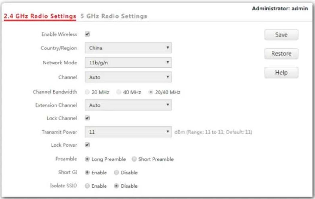
7.2.2 Changing the radio settings
- Choose Wireless Settings > Radio Settings.
- Click a tag page as required, which is 2.4 GHz Radio Settings in this example.
- Change the parameters as required. Generally, you only need to change the Enable Wireless, Channel, and Lock Channel settings.
- Click Save.
---End
Parameter description
| Parameter Description | |
| Enable Wireless | It specifies whether to enable the radio function of the AP. |
| Country/Region | It specifies the country or region where the AP is used. This parameter helps comply with channel regulations of the country or region. |
| Network Mode | It specifies the WiFi network mode of the AP, which includes 11b, 11g, 11b/g, and 11b/g/n. This parameter can be set if Lock Channel is not selected.11b: Only wireless devices compliant with 802.11b can connect to the 2.4 GHz WiFi network of the AP.11g: Only wireless devices compliant with 802.11g can connect to the 2.4 WiFi networks of the AP.11b/g: Only wireless devices compliant with 802.11b or 802.11g can connect to the 2.4 WiFi networks of the AP.11b/g/n: Wireless devices compliant with 802.11b or 802.11g, or they work at 2.4 GHz and compliant with 802.11n, can connect to the 2.4 WiFi networks of the AP.11a: Only wireless devices compliant with 802.11a can connect to the 5 GHz WiFi network of the AP.11ac: Only wireless devices compliant with 802.11ac can connect to the 5 GHz WiFi network of the AP.11a/n: Wireless devices compliant with 802.11a / 802.11n and work at 5 GHz can connect to the 5 WiFi networks of the AP. |
| Channel | It specifies the operating channel of the AP. This parameter can be set if Lock Channel is not selected. If you select Auto from the drop-down-list box, the AP adjusts its operating channel automatically according to the ambient environment. |
| Channel Bandwidth | It specifies the wireless channel bandwidth of the AP. This parameter can be set if the AP works in 802.11b/g/n, 802.11ac or 802.11a/n mode and Lock Channel is not selected.- 20 MHz: It indicates that the AP can use only 20 MHz channel bandwidth.- 40 MHz: It indicates that the AP can use only 40 MHz channel bandwidth.- 20/40 MHz: It indicates that the AP automatically adjusts its channel bandwidth to 20 MHz or 40 MHz according to the ambient environment.- 80 MHz: It indicates that the AP can use only 80 MHz channel bandwidth. |
| Extension Channel | It specifies the wireless extension channel of the AP. |
| Lock Channel | It is used to lock the channel settings of the AP. If this parameter is selected, channel settings including Country/Region, Network Mode, Channel, Channel Bandwidth, and Extension Channel cannot be changed. |
| Transmit Power | It specifies the transmit power of the AP. If the AP has a higher transmit power, its WiFi coverage is wider. However, reasonably decreasing the transmit power will improve the AP's WiFi network performance and security. |
| Lock Power | It specifies whether the current transmit power settings of the AP can be changed. If you tick this box, the current transmit power could not be changed. |
| Preamble | It specifies a group of bits located at the beginning of a packet, according to which the receiver of the packet can perform synchronization and prepare for receiving data. By default, the Long Preamble option is selected for compatibility with old network adopters installed on wireless devices. To achieve better synchronization performance of networks, you can select the Short Preamble option. |
| Short GI | It specifies short guard interval. Propagation delay of WiFi signal will happen to the receiving port during transmission. If the following data block is sent too fast, it will interfere the previous data block. A short guard interval can be used to circumvent this interference. Enabling the short GI function can yield a 10% improvement in data throughput. By default, this function is enabled. |
Parameter Description
| Isolate SSID | It specifies whether to isolate the wireless devices connected to the AP with different SSIDs. |
| Disable: It specifies the Isolate SSID function is disabled, so that the wireless devices connected to the AP with different SSIDs can communicate with each other. | |
| Enable: It specifies the Isolate SSID function is enabled, so that the wireless devices connected to the AP with different SSID cannot communicate with each other, which improves WiFi network security. |
7.3 Radio optimization
7.3.1 Overview
WiFi scenarios
WiFi scenarios are mainly divided into two types: ordinary ones and high-density ones.
Ordinary WiFi scenarios
They include WiFi network in places of wide WiFi coverage, such as offices, schools warehouses and hospitals. In general, comparing with a greater maximum number of clients, greater WiFi coverage is preferred in these scenarios.
■ High-density WiFi scenarios
They include WiFi network in large-scale places where a lot of end-user devices are used. Many APs are deployed for WiFi coverage in these places, such as meeting rooms, classrooms, stadiums, airports and train stations. In general, comparing with greater WiFi coverage, a greater maximum number of clients is preferred in these scenarios.
Performance optimization parameters
To fulfill different WiFi requirements in different WiFi scenarios, this AP supports several radio optimization parameters for users to have better WiFi network.
Prioritize 5 GHz
In general, channels of 2.4 GHz WiFi network are used more frequently and widely than those of 5 GHz WiFi network. But many channels of 2.4 GHz WiFi network are overlapped and congested, and interference between WiFi signals is strong as well. Comparatively, 5 GHz WiFi network provides more channels which are not overlapped. However, when devices supporting both 2.4 and 5 GHz WiFi signals connect to WiFi network, they connect to 2.4 GHz WiFi network first. This makes the channels of 2.4 GHz WiFi network more congested and wastes those of 5 GHz WiFi network.
When 5 GHz WiFi signal strength AP receives from an end-user device is higher than AP's 5 GHz threshold value, prioritize 5 GHz function of the AP enables the device to connect to AP's 5 GHz WiFi network first, making more devices to connect to 5 GHz WiFi network and improving network performance in 2.4 GHz WiFi network.

Note
Before the prioritize 5 GHz function is enabled, you should ensure both the 2.4 GHz and 5 GHz WiFi network are enabled, and SSIDs, security modes and WiFi password of 2.4 GHz and 5 GHz WiFi network are the same as each other.
Air Interface Scheduling
FIFO (First in first out) is used in traditional packet scheduling. In WiFi environment of mixed rates, high-speed users have stronger transmission capability, higher spectrum efficiency, but less air interface time, while low-speed users have weaker transmission capability, lower spectrum efficiency, but more air interface time, which reduces AP's throughput rate and working efficiency.
Air interface scheduling of this AP distributes downlink transmission time to users fairly, making users of different speeds get the same downlink transmission time, achieving higher throughput rate and greater concurrent users for the AP.
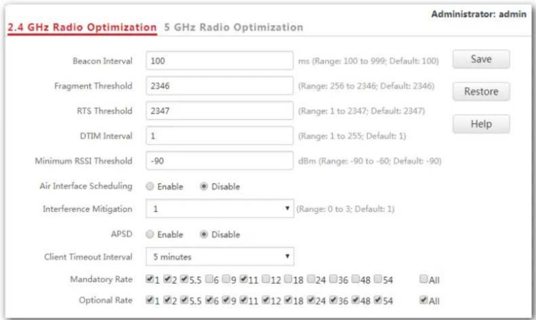
7.3.2 Changing the radio optimization settings

Note
It is recommended to change the settings only under the instruction of professional personnel, so as to prevent wireless performance from getting worse.
- Choose Wireless Settings > Radio Optimization.
- Click a tag page as required, which is 2.4 GHz Radio Optimization in this example.
- Change the parameter settings as required.
- Click Save.
---End
Parameter description
| Parameter Description | |
| Beacon Interval | It specifies the interval for transmitting the Beacon frame.The Beacon frame is transmitted at the specified interval to announce the presence of a wireless network. Generally, a smaller interval enables wireless devices to connect to the AP more quickly, while a larger interval ensures higher data transmission speed for the AP. |
| Fragment Threshold | It specifies the threshold of a fragment. Unit of this parameter is byte.Fragmenting is a process that divides a frame into several fragments, which are transmitted and acknowledged separately. If the size of a frame exceeds this threshold, the frame is fragmented.In an environment of high error rate, you can reduce the threshold to enable the AP to resend only the fragments that have not been sent successfully, so as to increase the frame throughput.In an environment without interference, you can increase the threshold to reduce the number of acknowledgement times, so as to increase the frame throughput. |
| RTS Threshold | It specifies the frame length threshold for triggering the RTS/CTS mechanism. Unit of this parameter is byte.If a frame exceeds this threshold, the RTS/CTS mechanism is triggered to reduce conflicts.Set the RTS threshold based on the actual situation. An excessively small value increases the RTS frame transmission frequency and bandwidth requirement. A higher RTS frame transmission frequency enables a WiFi network to recover from conflicts quicker. For a WiFi network with high user density, you can reduce this threshold for reducing conflicts. The RTS mechanism requires some network bandwidth. Therefore, it is triggered only when frames exceed this threshold. |
| DTIM Interval | It specifies the interval for transmitting the Delivery Traffic Indication Message (DTIM) frame. Unit of this parameter is Beacon.A countdown starts from this value. The AP transmits broadcast and multicast frames in its cache only when the countdown reaches zero.For example, if DTIM Interval is set to 1, the AP transmits all cached frames after each beacon frame is transmitted. |
| Minimum RSSI Threshold | Set a minimum strength of received signals acceptable to the AP. If the strength of the signals transmitted by a wireless device is weaker than this threshold, the wireless device cannot connect to the AP.If there are multiple APs, an appropriate Minimum RSSI Threshold ensures that wireless devices can connect to the AP' WiFi networks with strong signals. |
| Prioritize 5 | It specifies whether to enable the Prioritize 5 GHz function. If the function is enabled, devices supporting 5 GHz WiFi network connects to AP's 5 GHz |
| GHz | WiFi network first. Otherwise, devices connects to 2.4GHz or 5 GHz WiFi network randomly. This parameter only appears on the5 GHz Radio Optimization page. |
| 5 GHz Threshold | When Prioritize 5 GHz function is enabled, if the 5 GHz WiFi signal strength AP receives from end user is higher than the 5 GHz threshold value, end users connect to AP's 5 GHz WiFi network first. Otherwise, end users connect to 2.4 GHz WiFi network first. |
| Air Interface Scheduling | Used to enable/disable the air interface scheduling function.It helps equal clients' transmission time, thus improving the experience of clients with high transmission rate. |
| Interference Mitigation | Select an interference mitigation mode for your AP.-0: The energy detection mechanism is disabled.-1: The energy detection mechanism is enabled. When the received signal strength is weaker than -70 dBm, this device stops transmitting data, so as to prevent packet loss due to interference.-2: The energy detection mechanism is enabled. When the received signal strength is weaker than -50 dBm, this device stops transmitting data, so as to prevent packet loss due to interference.-3: The energy detection mechanism is enabled. When the received signal strength is weaker than -70 dBm, this device automatically switches to a better channel. |
| APSD | It enables the AP to reduce power consumption after a specified period during which no traffic is transmitted or received by the AP. By default, it is disabled. |
| MU-MIMO | Multi-User Multiple-Input Multiple-Output. After this function is enabled, AP can communicate with multiple users concurrently, avoiding WiFi network congestion and improving communication. This parameter only appears on the5 GHz Radio Optimization page. |
| Client Timeout Interval | It specifies the wireless device disconnection interval of the AP. The AP disconnects a wireless device if no traffic is transmitted or received by the wireless client within the interval. |
| Mandatory Rate | Select the transmission rate sets you want the AP to support. Wireless devices must supports the basic rate sets you select, or they cannot connect to the AP's WiFi networks. |
| Optional Rate | Select the transmission rate sets you want the AP to support. Unlike the basic rate sets, it is acceptable for wireless devices not to support the supported rate sets you select. |
7.4 Frequency analysis
7.4.1 Overview
This module consists of two functions: frequency analysis and rouge AP detection.
Frequency analysis
This function enables you to check number of signals in every channel and the channel usage. You can select a channel with a low usage for your AP to improve wireless data transmission.
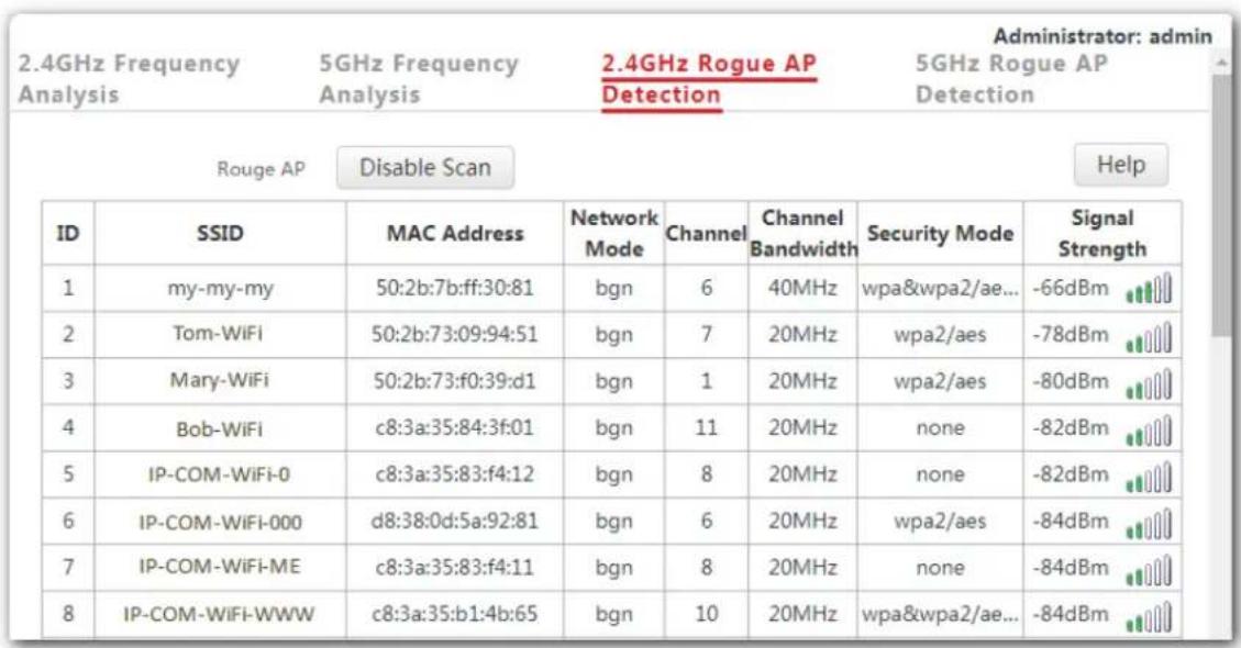
Rouge AP detection
This function enables you to know about the wireless signals near the AP, including information about SSID, MAC address, channel and signal strength.
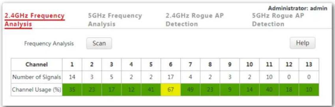
7.4.2 Checking frequency analysis
- To access the configuration page, click Wireless Settings > Frequency Analysis.
- Click 2.4GHz Frequency Analysis or 5GHz Frequency Analysis based on your need.
- Frequency Analysis: Click Scan.
| 2.4GHz Frequency Analysis | 5GHz Frequency Analysis | 2.4GHz Rogue AP Detection | Administrator: admin 5GHz Rogue AP Detection |
| Frequency Analysis | Scan | Help |
---End
After clicking Scan, you can select a channel with a low usage for your AP based on the results.
- If the underpainting of the channel usage is green, it indicates the channel is not congested.
- If the underpainting of the channel usage is yellow, it indicates the channel is congested.
- If the underpainting of the channel usage is red, it indicates the channel is so congested that it nearly could not be used.
7.4.3 Detecting rogue APs
- To access the configuration page, click Wireless Settings > Frequency Analysis.
- Click 2.4GHz Rogue AP Detection or 5GHz Rogue AP Detection based on your need.
- Rogue AP: Click Scan.
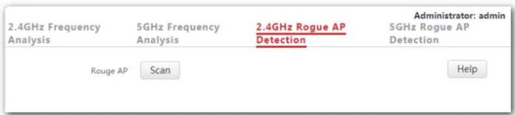
---End
Wait a minute. Then the scanning result appears. See the following figure:
7.5 WMM settings
7.5.1 Overview
802.11 networks offer wireless access services based on the Carrier Sense Multiple Access with Collision Avoidance (CSMA/CA) channel competition mechanism, which allows all wireless devices to fairly compete for channels. All the services implemented over WiFi networks share the same channel competition parameters. Nevertheless, different services usually have different requirements for bandwidth, delay, and jitter. This requires wireless networks to offer accessibility based on the services implemented over the networks.
WMM is a wireless QoS protocol used to ensure that packets with high priorities are transmitted first. This ensures better experience of voice and video service over WiFi networks.
WMM involves the following terms:
- Enhanced Distributed Channel Access (EDCA): It is a channel competition mechanism to ensure that packets with higher priorities are assigned more bandwidth and transmitted earlier.
- Access Category (AC): The WMM mechanism divides WLAN traffic by priority in descending order into the AC-VO (voice stream), AC-VI (video stream), AC-BE (best effort), and AC-BK (background) access categories. The access categories use queues with different priorities to send packets. The WMM mechanism ensures that packets in queues with higher priorities have more opportunities to access channels.
According to the 802.11 protocol family, all devices listen on a channel before using the channel to send data. If the channel stays idle for or longer than a specified period, the devices wait a random backoff period within the contention window. The device whose backoff period expires first can use the channel. The 802.11 protocol family applies the same backoff period and contention window to all devices across a network to ensure that the devices have the same channel contention opportunity.
EDCA Parameters
WMM changes the contention mechanism of 802.11 networks by dividing packets into four ACs, among which the ACs with higher priorities have more opportunities to access channels. The ACs help achieve different service levels.
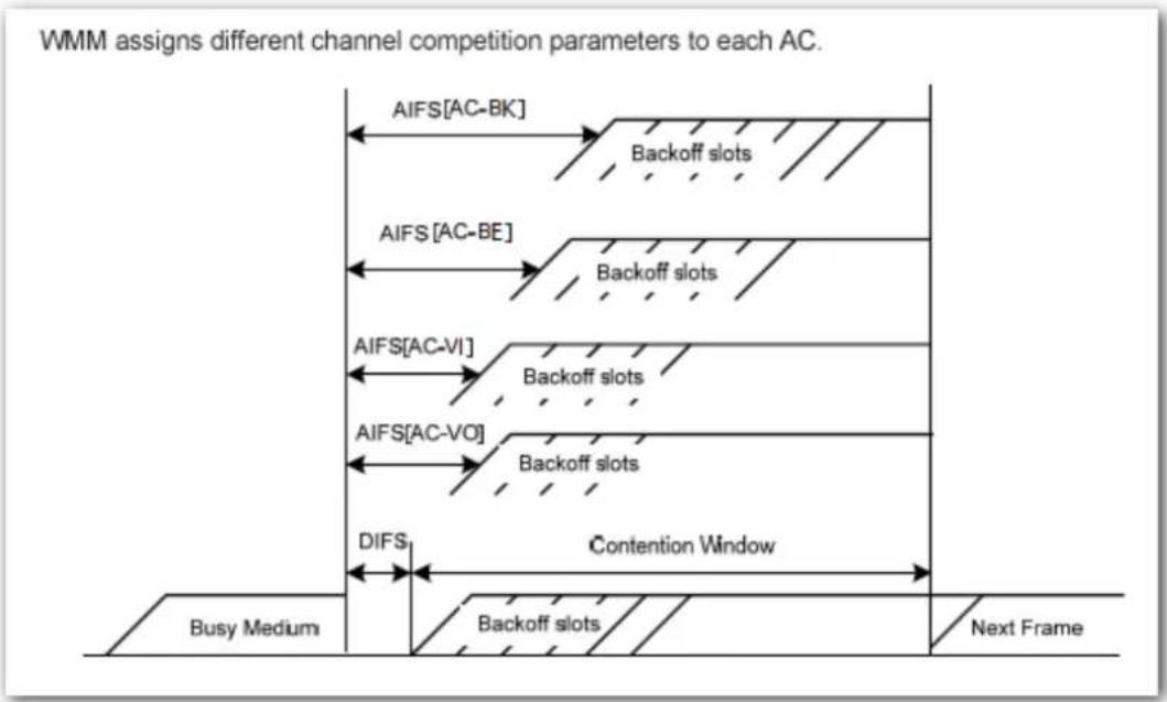
WMM assigns each AC a set of EDCA parameters for channel contention, including:
- Arbitration Inter Frame Spacing Number (AIFSN): Different from the fixed distributed inter-frame spacing (DIFS) specified in the 802.11 protocol family, AIFSN varies across ACs. A greater AIFSN indicates a longer backoff period. See AIFS in the following figure.
- Contention window minimum (CWmin) and contention window maximum (CWmax) specify the average backoff period. The period increases along with these two values. See the backoff slots in the following figure.
- Transmission Opportunity (TXOP): It specifies the maximum channel use duration after successful channel contention. The duration increases along with this value. The
value 0 indicates that a device can send only one packet through a channel after winning contention for the channel.
flowchart
graph TD
    A["Busy Medium"] --> B["DIFS"]
    B --> C["Backoff slots"]
    C --> D["Contention Window"]
    D --> E["Next Frame"]
    F["AIFS[AC-BK"]] --> G["Backoff slots"]
    H["AIFS[AC-BE"]] --> I["Backoff slots"]
    J["AIFS[AC-VI"]] --> K["Backoff slots"]
    L["AIFS[AC-VO"]] --> M["Backoff slots"]
    N["AIFS[AC-BK"]] --> O["Backoff slots"]
    P["AIFS[AC-BE"]] --> Q["Backoff slots"]
    R["AIFS[AC-VI"]] --> S["Backoff slots"]
    T["AIFS[AC-VO"]] --> U["Backoff slots"]
    V["AIFS[AC-BK"]] --> W["Backoff slots"]
    X["AIFS[AC-BE"]] --> Y["Backoff slots"]
    Z["AIFS[AC-VI"]] --> AA["Backoff slots"]
    AB["AIFS[AC-VO"]] --> AC["Backoff slots"]
    AD["AIFS[AC-BK"]] --> AE["Backoff slots"]
    AF["AIFS[AC-BE"]] --> AG["Backoff slots"]
    AH["AIFS[AC-VI"]] --> AI["Backoff slots"]
    AJ["AIFS[AC-VO"]] --> AK["Backoff slots"]
    AL["AIFS[AC-BK"]] --> AM["Backoff slots"]
    AN["AIFS[AC-BE"]] --> AO["Backoff slots"]
    AP["AIFS[AC-VI"]] --> AQ["Backoff slots"]
    AR["AIFS[AC-VO"]] --> AS["Backoff slots"]
    AT["AIFS[AC-BK"]] --> AU["Backoff slots"]
    AV["AIFS[AC-BE"]] --> AW["Backoff slots"]
    AX["AIFS[AC-VI"]] --> AY["Backoff slots"]
    AZ["AIFS[AC-VO"]] --> BA["Backoff slots"]
    BB["AIFS[AC-BK"]] --> BC["Backoff slots"]
    BD["AIFS[AC-BE"]] --> BE["Backoff slots"]
    BF["AIFS[AC-VI"]] --> BG["Backoff slots"]
    BH["AIFS[AC-VO"]] --> BI["Backoff slots"]
    BJ["AIFS[AC-BK"]] --> BK["Backoff slots"]
    BL["AIFS[AC-BE"]] --> BM["Backoff slots"]
    BN["AIFS[AC-VI"]] --> BO["Backoff slots"]
    BP["AIFS[AC-VO"]] --> BP1["Backoff slots"]
    BQ["AIFS[AC-BK"]] --> BR["Backoff slots"]
    BS["AIFS[AC-BE"]] --> BT["Backoff slots"]
    BU["AIFS[AC-VI"]] --> BV["Backoff slots"]
    BW["AIFS[AC-VO"]] --> BX["Backoff slots"]
    BY["Busy Medium"] --> BZ["Diffs"]
ACK Policies
WMM specifies the Normal ACK and No ACK policies.
According to the No ACK policy, no ACK packet is used during wireless packet transmission to acknowledge packet reception. This policy is applicable to scenarios where interference is mild and can effectively improve transmission efficiency. In case of strong interference, lost packets are not sent again if this policy is adopted. This leads a higher packet loss rate and reduces the overall performance.
- According to the Normal ACK policy, each time a receiver receives a packet, it sends back an ACK packet to acknowledge packet reception.
7.5.2 Changing the WMM settings
By default, the WMM function of the AP is enabled and the Optimized for scenario with more than 10 users mode is adopted. The following procedures describe how to set the WMM settings:
- Choose Wireless Settings > WMM Setting.
- Click a tag page as required, which is 2.4 GHz WMM in this example.
- Set WMM Settings to Enable.
- Optimization Mode: Select the required WMM optimization mode. If you select Custom, set the WMM parameters as required.
- Click Save.
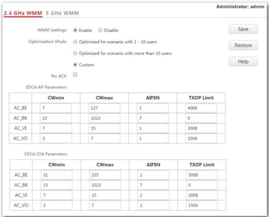
---End
Parameter description
| Parameter Description | |
| WMM Settings | - Enable: It is used to enable the WMM function. - Disable: It is used to disable the WMM function. |
| Optimization Mode | It specifies the WMM optimization modes supported by the AP: - Optimized for scenario with 1 - 10 users: If 10 or less devices are connected to the AP, you are recommended to select this mode to increase device throughput. - Optimized for scenario with more than 10 users: If more than 10 devices are connected to the AP, you are recommended to select this mode to ensure device connectivity. - Custom: This mode enables you to set the WMM EDCA parameters for manual optimization. |
| No ACK | This item appears only after you set your Optimization Mode as Custom. - If the box is ticked, the No ACK policy is adopted. - If the box is unticked, the Normal ACK policy is adopted. |
| EDCA Parameters | For details, refer to section 7.5.1 Overview. |
7.6 Access control
7.6.1 Overview
It specifies that you can allow/disallow wireless devices with specified MAC addresses to access the AP's WiFi networks. The AP supports the following MAC address filter modes:
- Disable: It indicates that the access control function is disabled.
Allow: It indicates that only the wireless devices with the specified MAC addresses can access the specific WiFi network of AP. - Disallow: It indicates that only the wireless devices with the specified MAC addresses cannot access the specific WiFi network of AP.
7.6.2 Configuring access control
- Choose Wireless Settings > Access Control.
- Click a tag page as required, which is 2.4 GHz Access Control in this example.
- From the SSID drop-down list box, select the SSID on which the address access control function is implemented.
- Select an access control mode from the MAC Address Filter Mode drop-down list box.
- If you select Disable, the Access Control function will be disabled.
- If you select Allow or Disallow, enter the MAC addresses you want to control in the access control list and click Add.
If you want to control a wireless device that has been connected to the AP, directly click Add corresponding to the device.
5. Click Save.
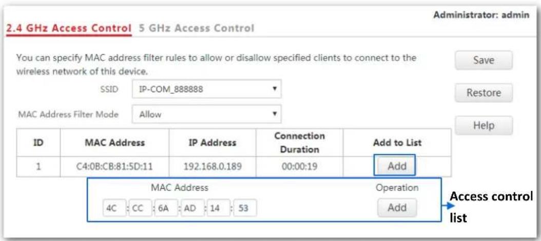
---End
Parameter description
| Parameter Description | |
| SSID | It specifies the SSID on which the MAC address access control is implemented. |
| MAC Filter Mode | It specifies the mode to disallow/allow device with specific MAC addresses to access the selected SSID, or allow all devices to access the selected SSID.·Disable: It indicates that access control function is disabled.·Allow: It indicates that only the wireless devices in the access control list can access the specific WiFi network with the selected SSID.·Disallow: It indicates that only the wireless devices in the access control list cannot access the specific WiFi network with the selected SSID. |
7.6.3 Example
Networking requirement
2.4 GHz WiFi network with a SSID Hotel WiFi has been set up in a hotel. However, it is required that only staffs are allowed to connect to this WiFi network.
It is recommended for the administrator to configure AP's access control function. Assume that these staffs have three wireless devices with the following three MAC addresses:
C8:3A:35:00:00:01
C8:3A:35:00:00:02
C8:3A:35:00:00:03
Procedures: (2.4 GHz Access Control is used here because Hotel WiFi is 2.4 GHz WiFi network.)
- Choose Wireless Settings > Access Control.
- SSID: Select Hotel WiFi from the SSID drop-down list box.
- MAC Address Filter Mode: Select Allow from the drop-down list box.
- MAC Address: Enter C8:3A:35:00:00:01 in the access control list and click Add. Repeat this step to add C8:3A:35:00:00:02 and C8:3A:35:00:00:03 as well.
- Click Save.
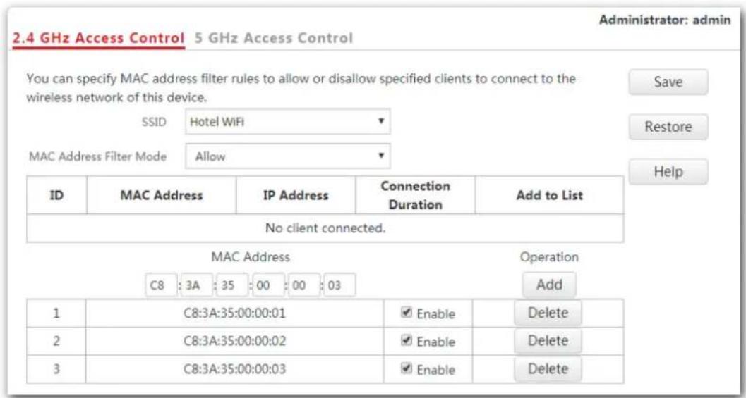
---End
The following figure shows the result after the configuration:
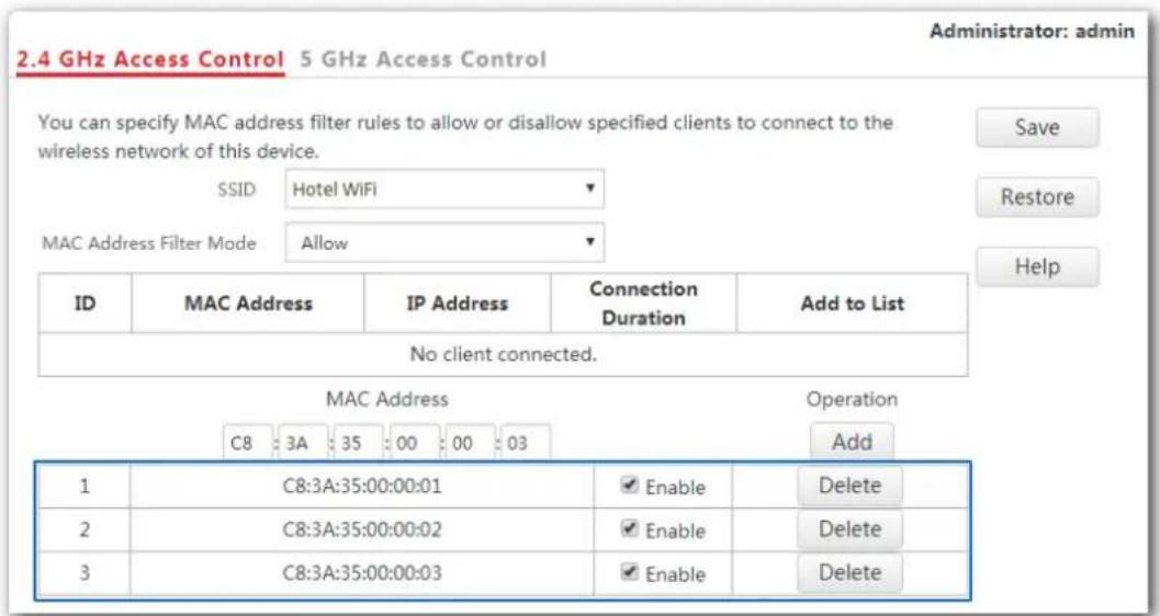
Verification
Only the three wireless devices on the access control list can connect to the Hotel WiFi WiFi network.
7.7 Advanced settings
7.7.1 Overview
This module enables you to make AP's WiFi network and wireless transmission more efficiently through enabling identifying client type and filtering broadcast packet. By default, these two functions are disabled.
7.7.2 Changing the advanced settings

Note
You are recommended to configure the broadcast packet filter function only under the instructions of professional personnel, so as to prevent decreasing the WiFi performance of the AP.
- Choose Wireless Settings > Advanced Settings.
- Identify Client Type, Broadcast Packet Filter, Filter Mode: Set the parameters as required.
- Click Save.
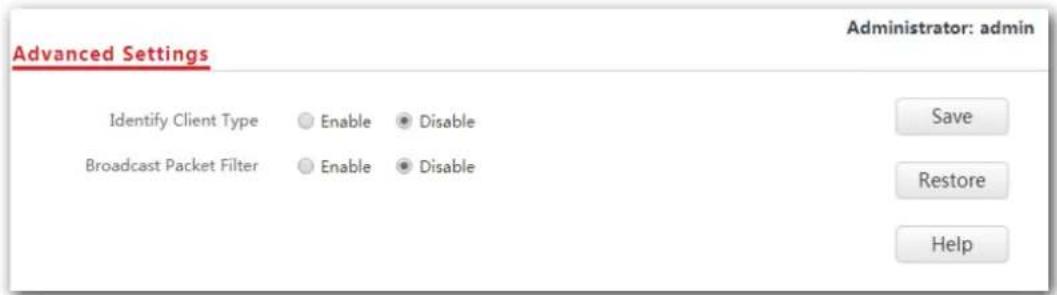
---End
Parameter description
| Parameter Description | |
| Identify Client Type | It specifies whether to recognize and display operating systems of the devices connected to AP's WiFi networks.·Disable: Click the circle beside it to disable the identifying client type function.·Enable: Click the circle beside it to enable the identifying client type function. After this function is enabled, you can see operating systems of connected devices on Status > Wireless clients page. |
| Broadcast Packet Filter | It specifies whether to enable the filtering broadcast packet function. By default, AP will forward lots of invalid broadcast packets, which may affect normal packets transmission. However, this function can filter broadcast packets and reduce airtime consumption, ensuring bandwidth of normal packets transmission.·Disable: Click the circle beside it to disable the filtering broadcast packet function.·Enable: Click the circle beside it to enable the filtering broadcast packet function. |
| Filter Mode | It specifies what packets AP will accept after users enable filtering broadcast packet function, consisting the following two modes:·Only accept DHCP and ARP packets: It indicates that the AP filters all broadcast or multicast packets except DHCP and ARP broadcast packets.·Only accept ARP packets: It indicates that the AP filters all broadcast or multicast packets except ARP broadcast packets. |
7.8 QVLAN settings
7.8.1 Overview
This AP supports the IEEE 802.1q VLAN function and can work with switches supporting that function to establish multiple VLANs. Devices connecting to VLANs with different VLAN IDs cannot communicate with each other. By default, the AP's QVLAN function is disabled.
7.8.2 Configuring the QVLAN settings
- Choose Wireless Settings > QVLAN Settings.
- Set the parameters as required. Generally, you only need to set the Enable, 2.4 GHz SSID VLAN ID and 5 GHz SSID VLAN ID settings.
- Click Save.
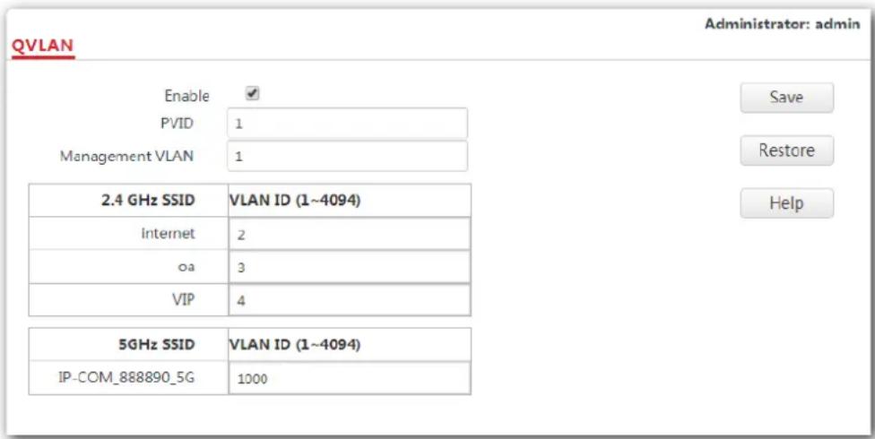
---End
Parameter description
| Parameter Description | |
| Enable | It specifies whether to enable the QVLAN function of the AP. By default, it is disabled. |
| PVID | It specifies the ID of the default native VLAN of the trunk port of the AP. The default value is 1. |
| Management VLAN | It specifies the ID of the AP management VLAN. The default value is 1. After changing the management VLAN, you can manage the AP only after connecting your computer or AP controller to the new management VLAN. |
| 2.4 GHz SSID | It specifies the currently enabled SSID(s) over the 2.4 GHz band of the AP. |
| 5 GHz SSID | It specifies the currently enabled SSID(s) over the 5 GHz band of the AP. |
| VLAN ID | It specifies the VLAN IDs corresponding to SSIDs. By default, this value is 1000.After the QVLAN function is enabled, the wireless ports corresponding to SSIDs functions as access ports. The PVID of an access port is the same as its VLAN ID. |
If the QVLAN function is enabled, tagged data received by a port of the AP is forwarded to the other ports of the VLAN corresponding to the VID in the data, whereas untagged data received by a port of the AP is forwarded to the other ports of the VLAN corresponding to the PVID of the port that receives the data.
The following table describes how ports of different link types process transmitted and received data.
| Port | Method to process received data | Method to process transmitted data | |
| Tagged data | Untagged data | ||
| Access | Forward the data to other ports of the VLAN corresponding to the VID in the data. | Forward the data to the other ports of the VLAN corresponding to the PVID of the port that receives the data. | Transmit data after removing tags from the data. |
| Trunk | If the VID and PVID of a port are the same, transmit data after removing tags from the data.If the VID and PVID of a port are different, transmit data without removing tags from the data. | ||
7.8.3 Example
Networking requirement
A hotel has the following WiFi network coverage requirements:
- Guests are allowed to connect to VLAN 2 and only able to access the internet.
- Hotel staffs are allowed to connect to VLAN 3 and only able to access the intranet.
- Hotel administrators are allowed to connect to VLAN 4, able to access both the intranet and the internet.
Assume that the SSID for guests is internet, the SSID for staffs is oa and the SSID for
administrators is VIP. The SSIDs are enabled and configured successfully on the AP.
Network topology
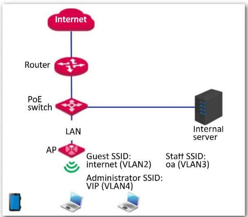
flowchart
graph TD
    A["Internet"] --> B["Router"]
    B --> C["PoE switch"]
    C --> D["LAN"]
    D --> E["AP"]
    E --> F["Guest SSID: internet (VLAN2)"]
    E --> G["Administrator SSID: VIP (VLAN4)"]
    H["Internal server"] --> I["Server"]
    style A fill:#f9f,stroke:#333
    style B fill:#f9f,stroke:#333
    style C fill:#f9f,stroke:#333
    style D fill:#ccf,stroke:#333
    style E fill:#cfc,stroke:#333
    style F fill:#fcc,stroke:#333
    style G fill:#fcc,stroke:#333
    style H fill:#fff,stroke:#333
    style I fill:#fff,stroke:#333
Procedures:
- Configure the AP.
(1) Log in to the web UI of the AP and choose Wireless > QVLAN Settings.
(2) Select the Enable check box.
(3) Change the VLAN ID of SSID internet to 2, VLAN ID of SSID oa to 3 and VLAN ID of SSID VIP to 4.
(4) Click Save.
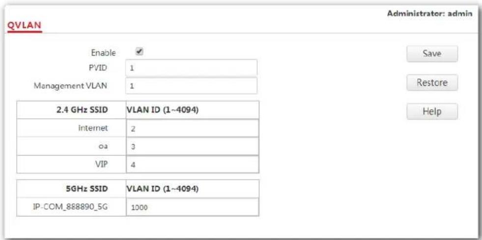
Wait for the automatic reboot of the AP.
2. Configure the switch.
Create IEEE 802.1Q VLANs described in the following table on the switch.
| Port Connected To | Accessible VLAN ID | Port Type | PVID |
| AP | 1, 2, 3, 4 | Trunk | 1 |
| Internal server 3, 4 Trunk 1 | |||
| Router 2, 4 Trunk 1 | |||
Retain the default settings of other ports. For details, refer to the user guide of the switch.
3. Configure the router and the internal server.
To ensure your wireless devices connected to the AP can access the internet, you should configure QVLAN function on your router and internal server which support QVLAN function. Detailed VLAN parameters are listed as follows:
VLAN parameters configured on your router:
| Port Connected To | Accessible VLAN ID | Port Type | PVID |
| Switch 2,4 Trunk 1 | |||
VLAN parameters configured on your internal server:
| Port Connected To | Accessible VLAN ID | Port Type | PVID |
| Switch 3,4 Trunk 1 | |||
For configuration details, refer to the user guides of your router and internal server.
---End
Verification
Wireless devices connected to the SSID internet can access only the internet. Wireless devices connected to the SSID oa can access only the intranet. Wireless devices connected to the SSID VIP can access both the internet and the intranet.
8 SNMP
8.1 Overview
The Simple Network Management Protocol (SNMP) is the most widely used network management protocol in TCP/IP networks. SNMP enables you to remotely manage all your network devices compliant with this protocol, such as monitoring the network status, changing network device settings, and receiving network event alarms.
SNMP supports managing devices bought from various vendors automatically, regardless of physical differences among the devices.
8.1.1 SNMP management framework
The SNMP management framework consists of SNMP manager, SNMP agent, and Management Information Base (MIB).
SNMP manager: It is a system that controls and monitors network nodes using the SNMP protocol. Network Management System (NMS) is the most widely used SNMP manager in network environments. An NMS can be a dedicated network management server, or an application that implements management functions in a network device.
SNMP agent: It is a software module in a managed device. This module is used to manage data about the device and report the management data to an SNMP manager.
- MIB: It is a collection of managed objects, defining a series of attributes of managed objects, including names, access permissions, and data types of objects. Each SNMP agent has its own MIB. An SNMP manager can read and/or write objects in the MIB based on the permissions assigned to the SNMP manager.
An SNMP manager manages SNMP agents in an SNMP network. The SNMP manager exchanges management information with the SNMP agents using the SNMP protocol.
8.1.2 Basic SNMP operations
The AP supports the following basic SNMP operations:
- Get: An SNMP manager performs this operation to query the SNMP agent of the AP for values of one or more objects.
Set: An SNMP manager performs this operation to set values of one or more objects in the MIB of the SNMP agent of the AP.
8.1.3 SNMP protocol version
The AP is compatible with SNMP V1 and SNMP V2C and adopts the community authentication mechanism. Community name is used to define the relationship between an SNMP agent and an SNMP manager. If the community name contained in an SNMP packet is rejected by a device, the packet is discarded. A community name functions as a password to control SNMP agent access attempts of SNMP managers.
SNMP V2C is compatible with SNMP V1 and provides more functions than SNMP V1. Compared with SNMP V1, SNMP V2C supports more operations (GetBulk and InformRequest) and data types (such as Counter64), and provides more error codes for better distinguishing errors.
8.1.4 MIB introduction
An MIB adopts a tree structure. The nodes of the tree indicate managed objects. A path consisting of digits and starting from the root can be used to uniquely identify a node. This path is calling an object identifier (OID). The following figure shows the structure of an MIB. In the figure, the OID of A is 1.3.6.1.2.1.1, whereas the OID of B is 1.3.6.1.2.1.2.
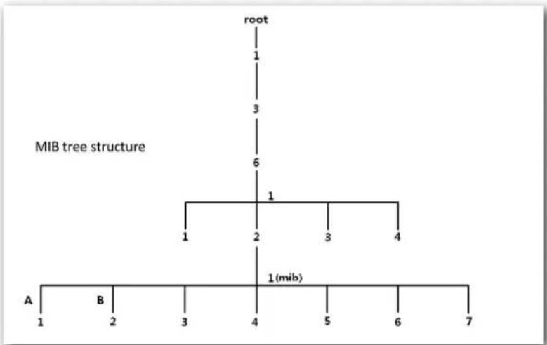
flowchart
graph TD
    A["root"] --> B["1"]
    B --> C["3"]
    C --> D["6"]
    D --> E["1"]
    E --> F["1"]
    E --> G["2"]
    G --> H["3"]
    H --> I["4"]
    I --> J["1 (mib)"]
    K["A"] --> L["1"]
    M["B"] --> N["2"]
    O["3"] --> P["4"]
    Q["5"] --> R["6"]
    S["7"] --> T["7"]
8.2 Configuring the SNMP function
- Click SNMP and set SNMP Agent to Enable.
- Set related SNMP parameters.
- Click Save.
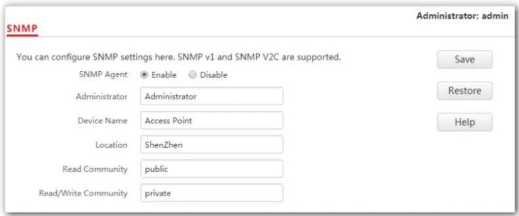
---End
Parameter description
| Parameter Description | |
| SNMP Agent | It specifies whether to enable the SNMP agent function of the AP. By default, it is disabled.An SNMP manager and the SNMP agent can communicate with each other only when their SNMP versions are the same. Currently, the SNMP agent function of the AP supports SNMP V1 and SNMP V2C. |
| Administrator | It specifies the administrator's name of the AP. The default name is Administrator. You can change the administrator's name if required. |
| Device Name | It specifies the device name of the AP. By default, the device name is Access Point. You can change it if required. You are recommended to change the AP name so that you can identify your AP easily when managing the AP using SNMP. You are recommended to change the AP name so that you can identify your AP easily when managing the AP using SNMP. |
| Location | It specifies the location where the AP is used. You can change the location according to your actual situation. |
| Read Community | It specifies the read password shared between SNMP managers and the SNMP agent. The default password is public.The SNMP agent function of the AP allows an SNMP manager to use the password to read variables in the MIB of the AP. |
| Read/Write Community | It specifies the read/write password shared between SNMP managers and the SNMP agent. The default password is private.The SNMP agent function of the AP allows an SNMP manager to use the password to read/write variables in the MIB of the AP. |
8.3 Example
Networking requirement
The AP connects to an NMS over an LAN network. This IP address of the AP is 192.168.0.254/24 and the IP address of the NMS is 192.168.0.212/24.
- The NMS uses SNMP V1 or SNMP V2C to monitor and manage the AP.
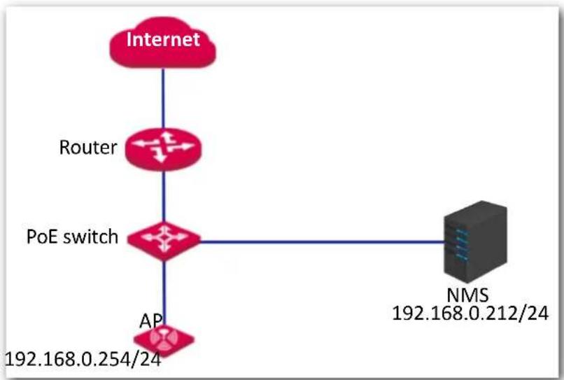
flowchart
graph TD
    A["Internet"] --> B["Router"]
    B --> C["PoE switch"]
    C --> D["NMS 192.168.0.212/24"]
    C --> E["AP 192.168.0.254/24"]
Procedure:
1. Configure the AP.
Assume that the administrator name is Tom, read community is Tom, and read/write community is Tom123.
(1) Log in to the web UI of the AP and choose SNMP.
(2) Set SNMP Agent to Enable.
(3) Set the SNMP parameters.
(4) Click Save.
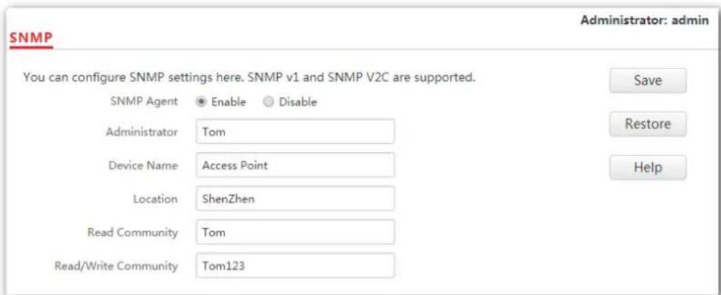
2. Configure the NMS.
On an NMS that uses SNMP V1 or SNMP V2C, set the read community to Tom and read/write community to Tom123. For details about how to configure the NMS, refer to the user guide of the NMS.
---End
Verification
After the configuration, the NMS can connect to the SNMP agent of the AP and can query and set some parameters on the SNMP agent through the MIB.
9 Deployment
9.1 Overview
If a large number of APs are deployed, you are recommended to adopt an IP-COM AP controller to manage the APs in a centralized manner, such as AC1000/2000/3000. The AP supports two deployment modes: local deployment and cloud deployment. By default, the AP is in local deployment mode.
Local deployment
If you need to deploy many APs in a small area, you are recommended to set the AP in the local deployment mode, which uses a local AC (in Sub AC mode) to manage the APs in a centralized manner. The following figure shows the topology for the local deployment mode.

flowchart
graph TD
    A["Internet"] --> B["Router"]
    B --> C["Core switch"]
    C --> D["AC"]
    C --> E["PoE switch"]
    E --> F["AP 1"]
    E --> G["AP 2"]
    E --> H["AP n"]
    F --> I["Laptop"]
    G --> J["Laptop"]
    H --> K["Laptop"]
Cloud deployment
If you need to deploy many APs distributed across a large area, you are recommended to select the cloud deployment mode, which uses an AC (in Cloud AC mode) over the internet to manage the APs in a centralized manner. The following figure shows the topology for the cloud deployment mode.
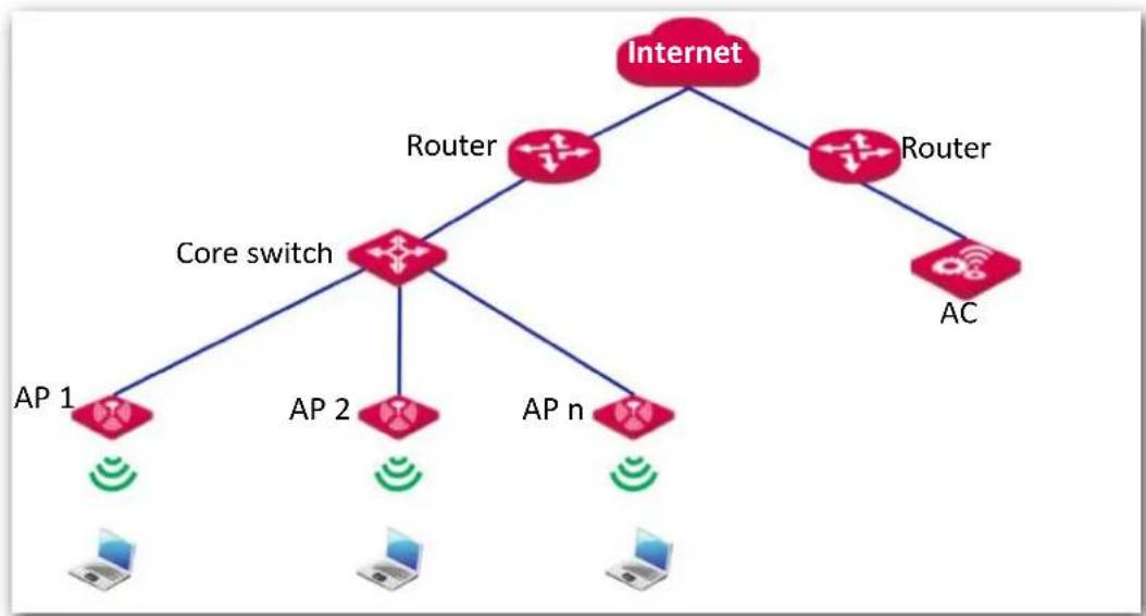
flowchart
graph TD
    A["Internet"] --> B["Router"]
    A --> C["Router"]
    B --> D["Core switch"]
    C --> E["AC"]
    D --> F["AP 1"]
    D --> G["AP 2"]
    D --> H["AP n"]
    F --> I["Laptop"]
    G --> J["Laptop"]
    H --> K["Laptop"]
9.2 Configuring the deployment mode
9.2.1 Configuring the local deployment mode
- Click Deployment, and select Local.
- Click Save.
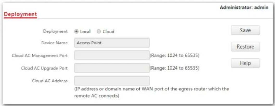
---End
9.2.2 Configuring the cloud deployment mode
- Click Deployment, and select Cloud.
- Set related parameters, including device name, cloud AC address, cloud AC manage port and cloud AC upgrade port.
- Click Save.
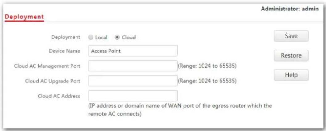
---End
Parameter description
| Parameter Description | |
| Deployment | It specifies the deployment mode of the AP. The default option isLocal.-Local: It indicates that the AP can be managed only through the AC connected to the same local network.-Cloud: In this mode, the AP can be managed only by a cloud AC or a cloud server. To adopt the cloud deployment mode, you should set the device name, cloud AC address, cloud AC manage port and cloud AC upgrade port for your AP as well. |
| Device Name | It specifies the device name of the AP. You are recommended to change the device name so that you can quickly locate the AP when managing the AP remotely. |
| Cloud AC Address | It specifies the WAN IP address of the router to which the cloud AC connects, or the domain name to which the router's WAN IP address is bound. |
| Cloud AC Manage Port | It specifies port of the egress router to which the cloud AC connects for managing this device. |
| Cloud AC Upgrade Port | It specifies port of the egress router to which the cloud AC connects for upgrading this device. |
10 Tools
10.1 Firmware upgrade
This function enables users to upgrade the AP's firmware for more functions and higher stability.

Note
To prevent damaging the AP, ensure that the new firmware version is applicable to the AP before upgrading the firmware, and keep powering on the AP during an upgrade.
Procedures:
- Download the latest firmware version for the AP from http://www.ip-com.com.cn to your local computer.
- Log in to the web UI of the AP and click Tools > Firmware Upgrade.
- Click Choose File and select the downloaded firmware file for upgrade.
- Click Upgrade.
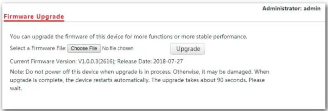
---End
Wait until the progress bar completes. Then log in to the web UI of the AP again. Click Status > System Status and check whether the upgrade is successful according to the Firmware Version parameter.

Note
After the firmware is upgraded, you are recommended to restore the factory settings of the AP and configure the AP again, so as to ensure stability of the AP and proper operation of new functions.
10.2 Date & time
This module enables you to set the system time and login timeout interval of your AP.
10.2.1 System time
Ensure that the system time of the AP is correct, so that logs can be recorded correctly and the reboot schedule can be executed correctly.
To access the page, click Tools > Date & Time.
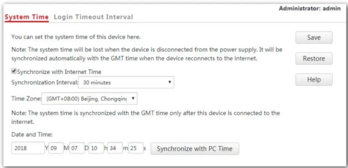
The AP allows you to set its system time by synchronizing the time with the internet or setting the time manually. By default, the AP is configured to synchronize the system time with the internet.
Parameter description
| Parameter Description | |
| Synchronize with Internet Time | Tick the box beside this item to synchronize the AP’s system time with the internet time. |
| Synchronization Interval | It specifies the interval at which the AP synchronizes its system time with the internet time. |
| Synchronize with PC Time | Click this parameter to synchronize the AP’s system time with the system time of the computer used to manage the AP. |
Configuring AP to synchronizing with internet time
The AP automatically synchronizes its system time with a time server of the internet, which enables the AP to correct its system time automatically after being connected to the internet.
For details about how to connect the AP to the internet, refer to Quick setup.
Procedures:
- Click Tools > Date & Time > System Time.
- Tick the Synchronize with Internet Time box.
- Synchronization Interval: Select a desired value from the drop-down-list box. The default value 30 minutes is recommended.
- Set Time Zone to the time zone of your location.
- Click Save.
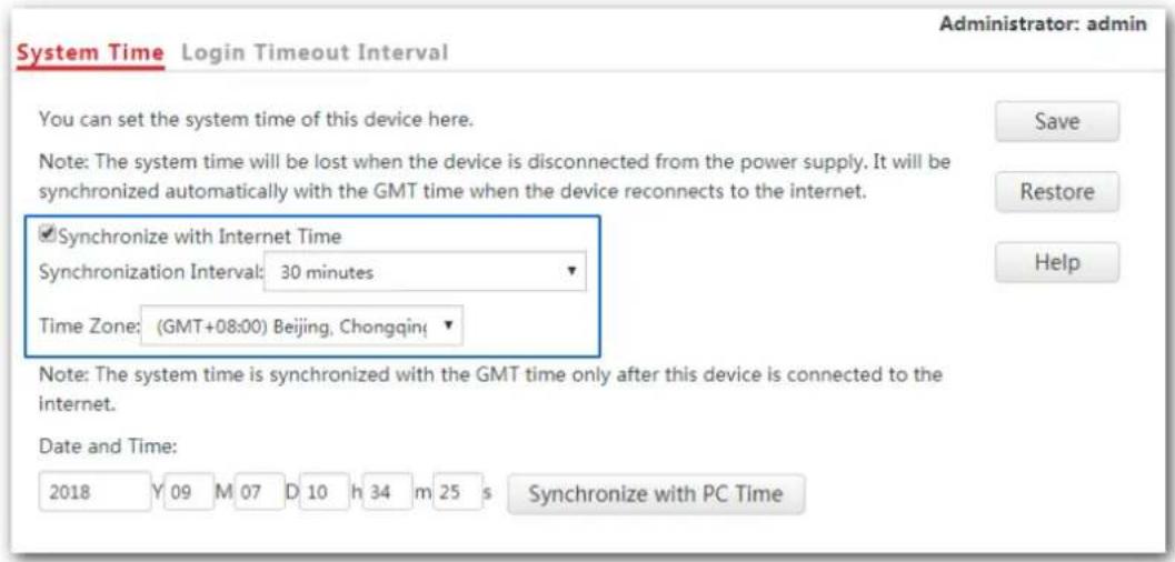
---End
Configuring date and time manually for AP
Users can manually set the system time for APs. If you choose to set date and time for your AP manually, you need to set the system time each time after the AP reboots.
Procedures:
- Click Tools > Date & Time > System Time.
- Enter a correct date and time, or click Synchronize with PC Time to synchronize the system time of the AP with the system time of the computer used to manage the AP.
- Click Save.
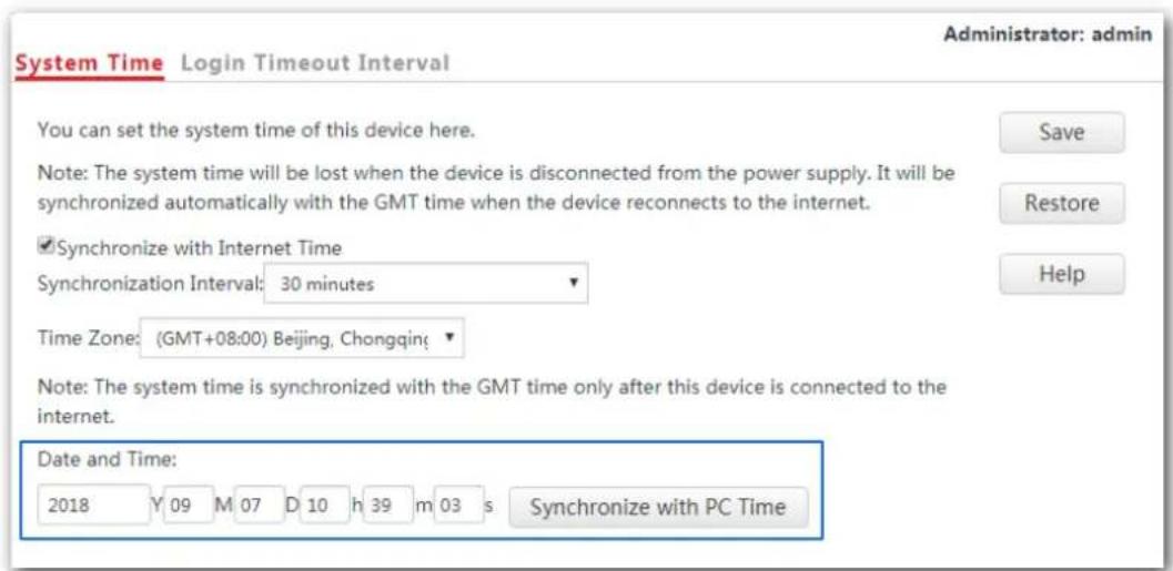

Note
If you decide to synchronize the system time of the AP with the system time of the computer used to manage the AP, make sure the computer's system time is correct.
---End
10.2.2 Login timeout interval
If you log in to the web UI of the AP and perform no operation within the login timeout interval, the AP logs you out automatically. The default login timeout interval is 5 minutes.
Configuring the login timeout interval:
- Click Tools > Date & Time, and click the Login Timeout Interval tab.
- Set the login timeout interval as required.
- Click Save.
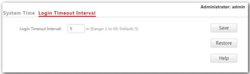
---End
10.3 Logs
This module enables you to view logs and configure log settings.
10.3.1 Logs
Logs record various events that occur to the AP and the operations that users perform on the AP after the AP starts. In case of system faults, refer to the logs during troubleshooting.
To access the page, click Tools > Logs.
| ID | Time | Type | Log Content |
| 16 | 2018-09-07 11:34:09 | system | web 192.168.0.10 login |
| 15 | 2018-09-07 11:33:13 | system | web 192.168.0.129 login |
| 14 | 2018-09-07 10:51:57 | system | web 192.168.0.129 login time expired |
| 13 | 2018-09-07 10:45:18 | system | web 192.168.0.129 login |
| 12 | 2018-09-07 10:44:57 | system | web 192.168.0.129 login time expired |
| 11 | 2018-09-07 10:34:22 | system | web 192.168.0.129 login |
To ensure that the logs are recorded correctly, make sure that AP's system time is correct. You can correct the system time by clicking Tools > Date & Time > System Time.
To view the latest logs of the AP, click Refresh. To clear the current logs, click Clear.

Note
When the AP reboots, the previous logs are lost. And the AP reboots when one of the followings happens: the AP is powered on after a power failure; the QVLAN function is configured; the firmware is upgraded; an AP configuration is backed up or restored or the AP is restored to factory settings.
10.3.2 Configuring log settings
To access the page, click Tools > Logs > Log Settings.
On this page, you can set the number of displayed logs and configure the log server function.
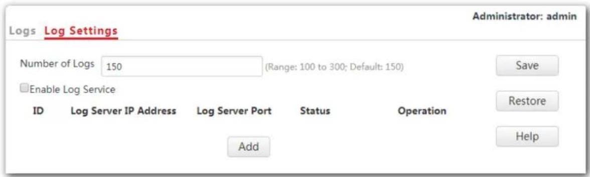
Setting the number of displayed logs
By default, the AP can display a maximum of 150 logs. You can change the number as required.
Procedure:
- To access the page, click Tools > Logs > Log Settings.
- Number of Logs: Change the number of logs as required within the range of 100 to 300.
- Click Save.
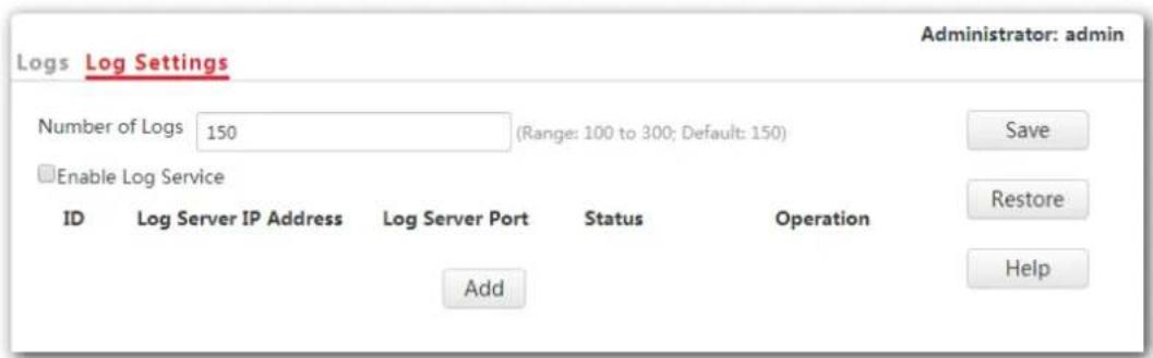
---End
Configuring the log server settings
After you specify a log server, the AP sends its logs to the log server. You can view all the historical logs of the AP on the log server.

Note
To ensure that system logs can be sent to a log server, choose Network Settings > LAN Setup and set the IP address, subnet mask, and gateway of the AP to communicate with the log server.
Adding a log server
- To access the page, click Tools > Logs > Log Settings.
- Click Add.
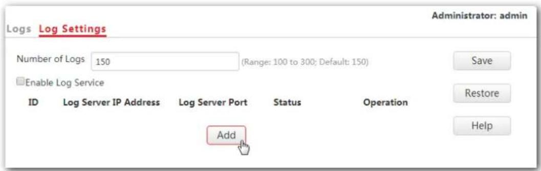
- Set parameters as follows:
Log Server IP Address: Enter the IP address of your log server, which is 192.168.0.88 in this example.
- Log Server Port: Enter the log server's UDP port number used to send and receive system logs. The default port number 514 is recommended.
- Status: Choose Enable.
- Click Save.
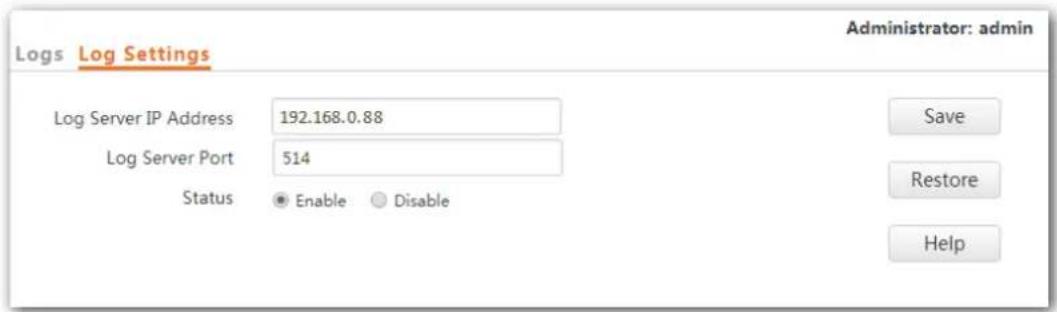
- Tick the box beside the Enable Log Service item.
- Click Save.
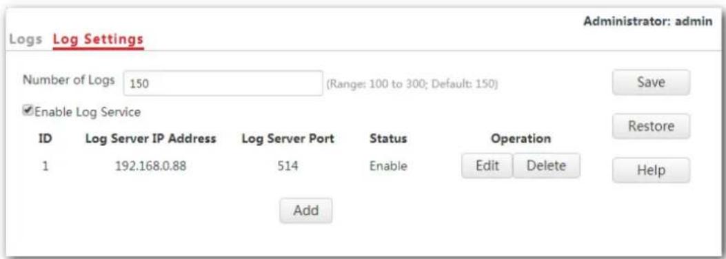
---End
The following figure shows the configuration:
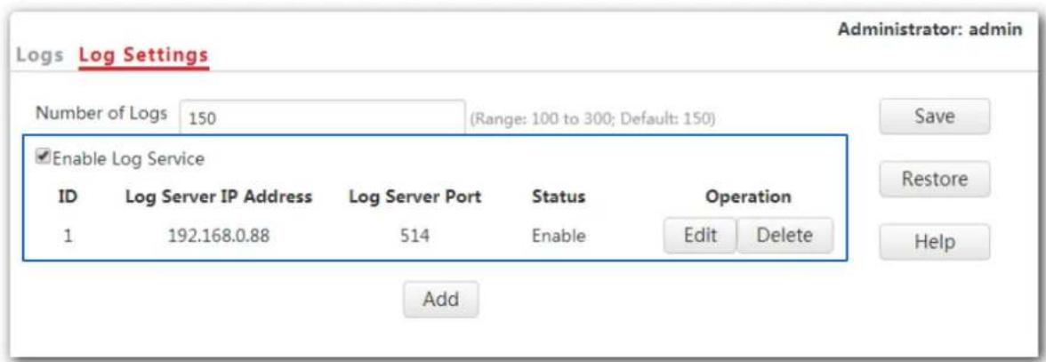
Changing log server settings
- To access the page, click Tools > Logs > Log Settings.
- Click Edit corresponding to the log server settings to be changed.
- Change the parameter settings as required.
- Click Save.
---End
Deleting log server settings
- To access the page, click Tools > Logs > Log Settings.
- Click Delete corresponding to the log server settings to be deleted.
---End
10.4 Configuration
This module enables you to back up the current configuration of the AP, restore a previous configuration of the AP, and restore the AP to factory settings.
10.4.1 Backup and restoring configurations
The backup function enables you to back up the current configuration of the AP to a local computer. The restoration function enables you to restore the AP to previous configuration.
If the AP enters the optimum condition after you greatly change the configuration of the AP, you are recommended to back up the new configuration, so that you can restore it after upgrading or resetting the AP.

Note
If you need to apply same or similar configuration to many APs, you can configure one of the APs, back up its configuration, and use the backup configuration file to restore the configuration of other APs.
Backup the current configuration
- Click Tools > Configuration > Backup & Restore.
- Click Backup.
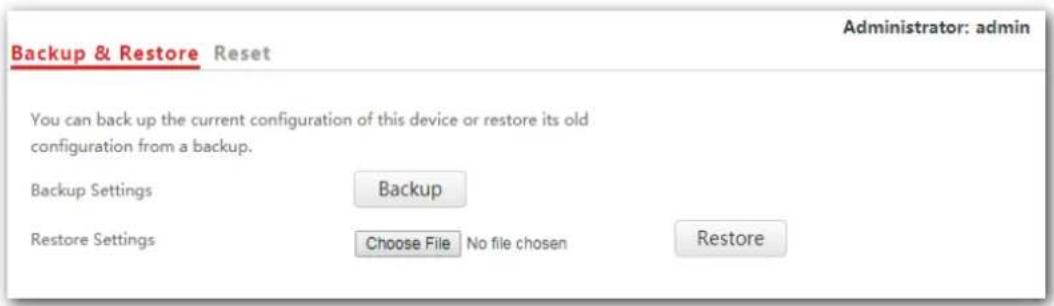
- Click OK.
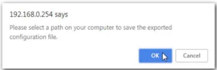
---End
A configuration file called as APCfm.cfg will be downloaded.
Restoring previous configuration
- Click Tools > Configuration > Backup & Restore.
- Click Choose File and select the configuration file to be restored.
- Click Restore.
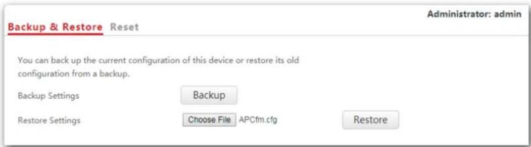
- Click OK.
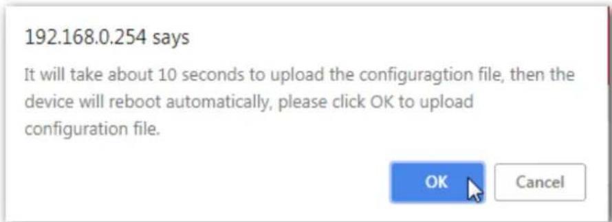
---End
A progress bar will appear after you click OK. And the AP is restored to previous configuration after the progress bar ends.
10.4.2 Resetting the AP
If you cannot locate a fault of the AP or forget the login password of the AP, you can reset the AP to restore its factory settings and then configure it again. The AP can be reset using web UI or hardware.
After you reset the AP, the login IP address of the AP is changed to 192.168.0.254, and the user name and password of the AP are changed to admin.

Note
- AP's configuration is lost if you restore it to the factory settings. And you need to reconfigure the AP to connect to the internet. Therefore, restore the factory settings of the AP only when necessary.
- To prevent damages, ensure that the AP is connected to power supply properly when the AP is reset.
Resetting the AP through web UI
- Click Tools > Configuration and click the Reset tab.
- Click the Reset button.
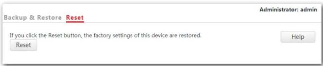
---End
Resetting the AP using hardware
This method enables you to reset the AP without logging in to its web UI.
After the LED indicator blinks, hold down the RESET button for about 8 seconds. The AP is reset successfully when the LED indicator gets solid on.
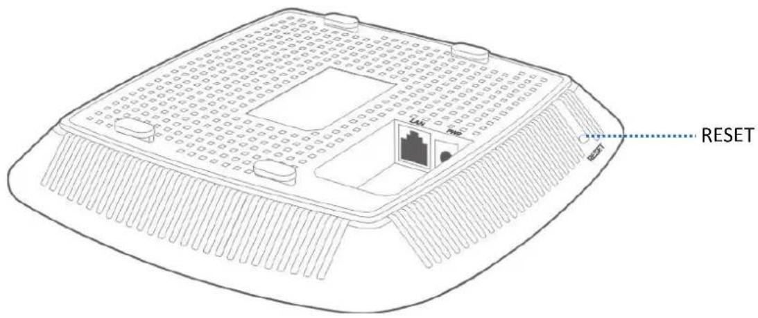
10.5 Account
This page enables you to change the AP's login account information such as user name and password to prevent unauthorized login.
To access the configuration page, click Tools > Account.
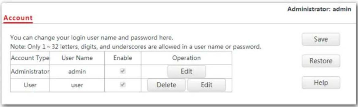
Parameter description
| Parameter Description | |
| Access Type | It specifies the account used to log in to the AP's web UI.-Administrator: It specifies the account enabling you to view and modify settings of the AP.-User: It specifies the account only enabling you to view settings of the AP. |
| User Name | It specifies the user name of an account.By default, the AP has one administrator account and one user account.Both the default user name and password of the administrator account are admin, and both the user name and password of the user account are user. |
| Enable | It specifies whether an account is enabled.-The administrator account is enabled for all time.-The user account is enabled by default but you can disable it if required. |
| Operation | -Change: Used to change the user name and password of the account corresponding to the button.-Delete: Used to delete the user account. NoteChanging, deleting, or adding an account succeeds only after you click Save. NoteChanging, deleting, or adding an account succeeds only after you click Save. |
Note
10.6 Diagnostics tool
If the network connection fails, you can use the diagnostics tool included in the AP to locate the faulty node.
10.6.1 Locating the faulty node
The link www.google.com is used as an example.
- Click Tools > Diagnostics Tool.
- Enter the IP address or domain name to be pinged in the Input box, which is www.google.com in this example.
- Click ping.
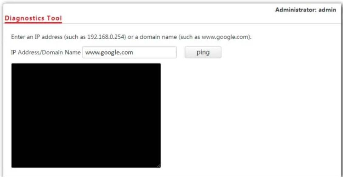
---End
The diagnosis result will be displayed in a few seconds in the black text box.
10.7 Reboot device
This module enables you to manually reboot the AP or configure the AP to reboot automatically.

Note
When the AP reboots, all connections are released. You are recommended to reboot the AP in spare time.
10.7.1 Manual reboot
If a setting does not take effect, you can try rebooting the AP to resolve the problem.
Procedures:
- To access the page, click Tools > Reboot Device.
- Click Reboot.
Manual Reboot Reboot Schedule
You can click the Reboot button to reboot this device immediately.
Reboot
---End
10.7.2 Reboot schedule
This function enables the AP to reboot automatically as scheduled. You can use this function to prevent wireless performance degradation or network instability that occurs after AP is online for a long time. The AP can reboot:
- At intervals: In this mode, the AP reboots at the interval you set.
- At specified time: In this mode, the AP reboots regularly at the time you set.
Configuring the AP to reboot at an interval
- Click Tools > Reboot Device and click the Reboot Schedule tab.
-
Tick the Enable Reboot Schedule box.
-
Reboot Mode: Select At Intervals.
- Interval: Set your required value, such as 1440 in this example.
- Click Save.
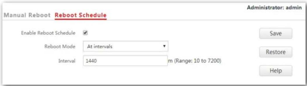
---End
Configuring the AP to reboot at specified time
- Click Tools > Reboot Device and click the Reboot Schedule tab.
- Tick the Enable Reboot Schedule box.
- Reboot Mode: Select At specified time.
- Reboot On: Select the required day(s) when the AP reboots, which is Monday in this example.
- Reboot At: Set the time when the AP reboots, which is 24:00 in this example.
- Click Save.
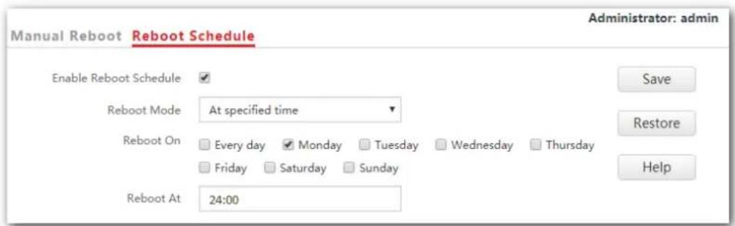
10.8 LED control
This function enables you to turn on/off the LED indicator of the AP. By default, the LED indicator is turned on.
Turning off the LED indicator:
- Click Tools > LED Control.
- Click Disable All LEDs.
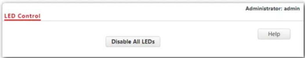
---End
Turning on the LED indicator:
- Click Tools > LED Control.
- Click Enable All LEDs.
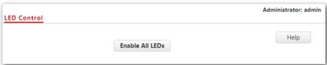
---End
10.9 Uplink check
10.9.1 Overview
In AP mode, the AP connects to its upstream network using the LAN port. If a critical node between the LAN port and the upstream network fails, the AP as well as the wireless devices connected to the AP cannot access the upstream network. If uplink detection is enabled, the AP regularly pings specified hosts through the LAN port. If all the hosts are not reachable, the AP stops its wireless service and wireless devices cannot find the SSIDs of the AP. The device can reconnect to the AP only after the connection between the AP and the upstream networks is recovered.
If the uplink of the AP with uplink check enabled is faulty, wireless devices can connect to the upstream network through another nearby AP that works properly.
See the following topology (The LAN port serves as the uplink port).
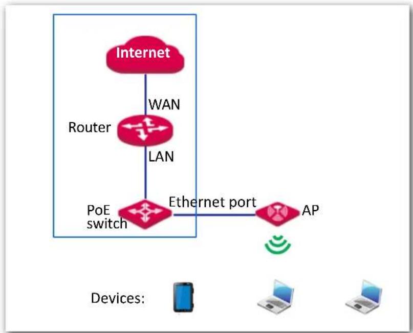
flowchart
graph TD
    A["Internet"] -->|WAN| B["Router"]
    B -->|LAN| C["PoE switch"]
    C --> D["Ethernet port"]
    D --> E["AP"]
    F["Devices: Smartphone"] --> G["Laptop"]
    H["Devices: Laptop"] --> I["Desktop"]
10.9.2 Configuring uplink check
-
Click Tools > Uplink Check.
-
Uplink Check: Tick the Enable box.
-
Host 1 to Ping/Host 2 to Ping: Enter the IP address(es) of the host to be pinged through the LAN port of the AP, such as the IP address of the switch or router directly connected to the AP.
-
Pinging Interval: Enter the interval at which the AP detects its uplink.
-
Click Save.
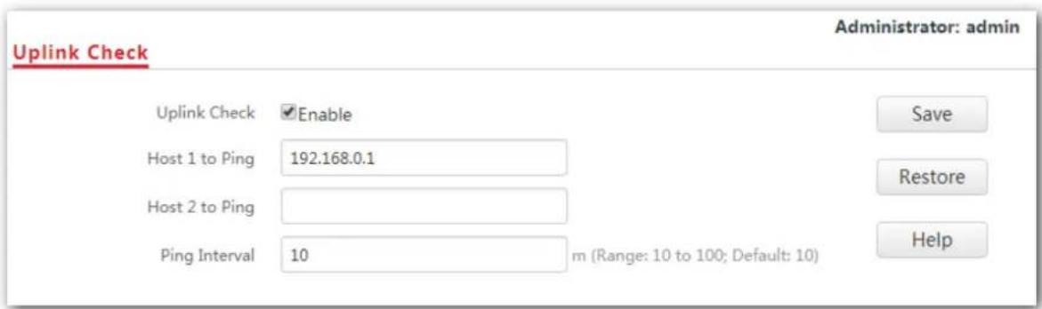
---End

Note
Host 1 to Ping is not bound with Host 2 to Ping, which indicates that you can enter IP address either in Host 1 to Ping or Host 2 to Ping, or enter IP addresses for both of these two parameters.
Appendix
A.1 Configuring a static IP address for your computer (Example: Win7)
Procedures:
- Right-click in the lower-right corner of the desktop and choose Open Network and Sharing Center.
Open Network and Sharing Center
- Click Local Area Connection.
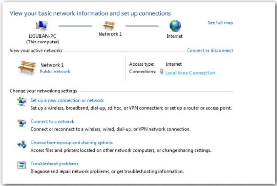
3. Click Properties.
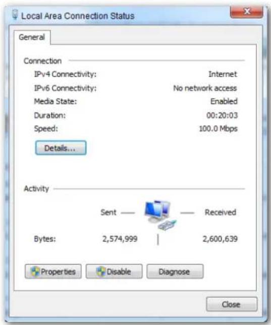
4. Double-click Internet Protocol Version 4 (TCP/IPv4).
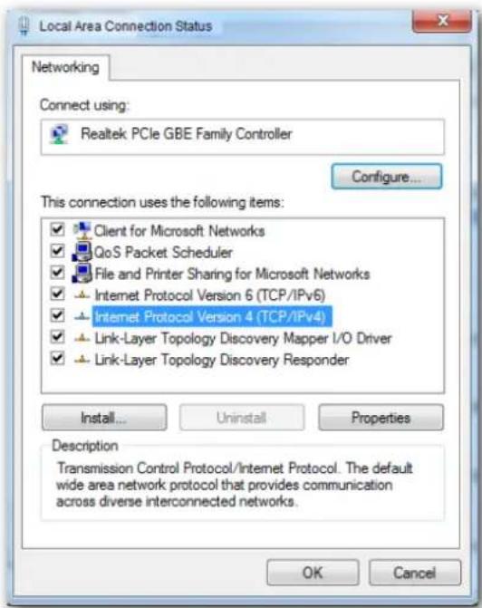
- Select Use the following IP address and Use the following DNS server address.
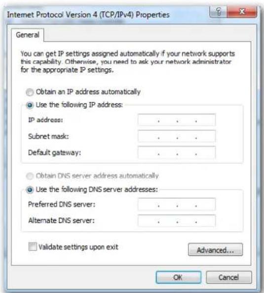
- IP address, Subnet mask: Set a static IP address, subnet mask for your computer, which is 192.168.0.10 and 255.255.255.0 in this example, and click OK.
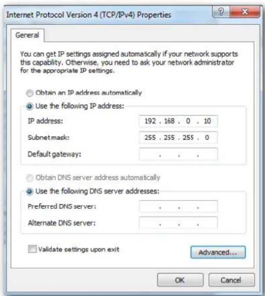
Verification
Configuration succeeds. You can check whether your configuration is successful on the Network Connection Details page. Procedures are as follows:
- Right-click in the lower-right corner of the desktop and choose Open Network and Sharing Center.
Open Network and Sharing Center
- Click Local Area Connection.
View your basic network information and set up connections

LIGUILAN-PC (This computer)

Network 1

Internet
See full map
View your active networks

Network 1 Public network
Access type: Connections
Internet
Local Area Connection
Change your networking settings

Set up a new connection or network
Set up a wireless, broadband, dial-up, ad hoc, or VPN connection; or set up a router or access point.

Connect to a network
Connect or reconnect to a wireless, wired, dial-up, or VPN network connection.

Choose homegroup and sharing options
Access files and printers located on other network computers, or change sharing settings.

Troubleshoot problems
Diagnose and repair network problems, or get troubleshooting information.
3. Click Details.
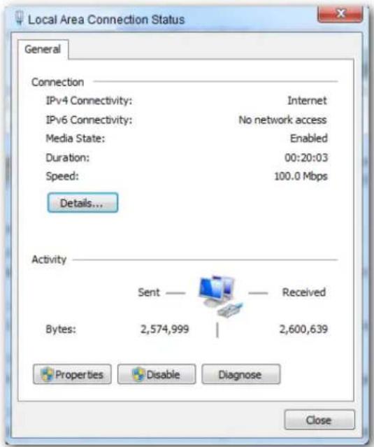
- Check whether your configuration is successful on the Network Connection Details page. Parameters in IPv4 Address, IPv4 Subnet Mask represent the IP address, subnet mask of your computer.
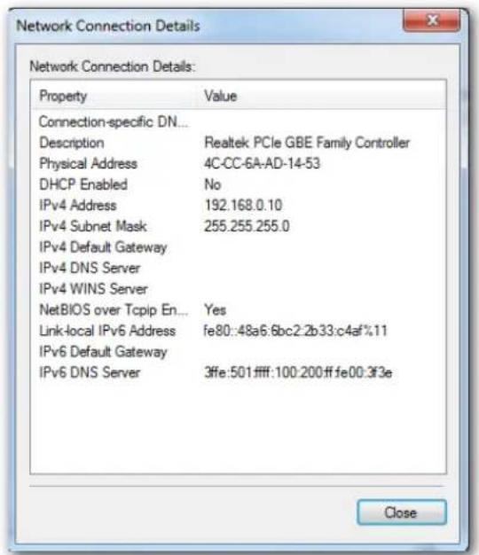
A.2 FAQ
Q1: I cannot access the web UI of the AP after entering 192.168.0.254. What should I do?
A1: Try the following solutions and log in again:
- Ensure that all your Ethernet cables are properly connected.
If there is no AC or IP-COM router in the network, ensure that the IP address of your computer has been set to 192.168.0.x (x: 2 to 253), and the IP address is not used by any other devices in the same network.
– Clear the cache of your web browser or replace the web browser. - Disable the firewall of your computer or replace your computer.
- If two or more APs are connected in the network without an AC/IP-COM management router, an IP address conflict may happen. You should leave only one AP in the network first and set a new IP address 192.168.0.x (x: 2 to 253) for the AP. Then repeat this procedure to change the IP addresses of the other APs. Meanwhile, make sure that the IP address of your computer is in the same network segment with your APs' new IP addresses. Then try logging in to the web UI of your APs using their new IP addresses.
- If the AP has been managed by the AC or IP-COM router, the AP's IP address may be no longer 192.168.0.254. In that case, go to the web UI of the AC/router to view the new IP address of the AP, and then log in to the AP's web UI using the new IP address.
- If the problem still persists, hold the RESET button down for 8 seconds to restore the AP to factory settings, and then try logging in again.
Q2: My AP controller (AC) cannot find my AP. What should I do?
A2: Check the following items:
- Ensure that all the devices in the network are connected properly and the LED of the AP blinks.
- If VLANs have been defined in your network, verify that the corresponding VLAN has been added to your AP controller.
- Reboot your AP.
- Ensure that the firmware versions of your AP and AC are the latest firmware versions available on http://www.ip-com.com.cn.
- Reset your AP.
Method to reset: When the system LED indicator blinks, hold down the RESET button for about 8 seconds. The AP is reset successfully when the system LED indicator gets solid on.
A.3 Default parameter values
The following table lists the default parameter values of the AP.
| Parameter Default Value | ||
| Login | Management IP address 192.168.0.254 | |
| Account Administrator | User name: admin | |
| Password: admin | ||
| Account User | User name: user | |
| Password: user | ||
| Quick Setup Working Mode AP Mode | ||
| LAN Setup | IP Address Type Static | |
| IP Address 192.168.0.254 | ||
| Subnet Mask 255.255.255.0 | ||
| Gateway 192.168.0.1 | ||
| Primary DNS Server 8.8.8.8 | ||
| Secondary DNS Server 8.8.4.4 | ||
| Device Name Access Point | ||
| Ethernet Mode Auto Negotiation | ||
| DHCP Server | DHCP Server | Disable |
| Start IP Address 192.168.0.100 | ||
| End IP Address | 192.168.0.200 | |
| Lease Time | 1 day | |
| Subnet Mask 255.255.255.0 | ||
| Gateway | 192.168.0.1 | |
| Primary DNS Server 8.8.8.8 | ||
| Secondary DNS Server | 8.8.4.4 | |
| SSID Settings | SSID 2.4 GHz5 GHz | The AP allows 8 SSIDs over the 2.4 GHz band. SSID is IP-COM_XXXXXX, and “XXXXXXXX” ranges from the last 6 digits of the AP’s LAN MAC address to the sum of the 6 digits and 7.As the primary SSID, the first SSID in the drop-down-list box is enabled by default, and the other SSIDs are disabled.The AP allows 4 SSIDs over the 5 GHz band. SSID is IP-COM_XXXXXX, and “XXXXXXXX” ranges from the sum of last 6 digits of the AP’s LAN MAC address and 8 to the sum of the 6 digits and 11.As the primary SSID, the first SSID in the drop-down-list box is enabled by default, and the other SSIDs are disabled. |
| Broadcast SSID Enable | ||
| Isolate Client Disable | ||
| WMF Enable | ||
| Suppress Broadcast Probe Response | Disable | |
| Max. Number of Clients 48 | ||
| Chinese SSID Encoding UTF-8 | ||
| Security Mode None | ||
| Radio Settings | Enable Wireless Enable | |
| Network Mode | 2.4 GHz 11b/g/n | |
| 5 GHz 11ac | ||
| Channel Auto | ||
| Channel Bandwidth | 2.4 GHz 20/40 MHz | |
| 5 GHz 80 MHz | ||
| Lock Channel Enable | ||
| Transmit Power | 2.4 GHz 11 dBm | |
| 5 GHz 14 dBm | ||
| Lock Power Enable | ||
| Preamble | Long Preamble | |
| Short GI Enable | ||
| Isolate SSID | Disable | |
| Radio Optimization | Beacon Interval | 100 ms |
| Fragment Threshold | 2346 | |
| RTS Threshold | 2347 | |
Parameter Default Value
| DTIM Interval 1 | ||
| Minimum RSSI Threshold | -90 dBm | |
| Prioritize 5 GHz Disable | ||
| 5 GHz Threshold -80 dBm | ||
| Interference Mitigation 1 | ||
| APSD Disable | ||
| MU-MIMO Disable (For 5GHz) | ||
| Client Timeout Interval 5 minutes | ||
| Mandatory Rate | 2.4GHz 1, 2, 5.5, 11 | |
| 5GHz 6, 12, 24 | ||
| Optional Rate | 2.4GHz 1, 2, 5.5, 6, 9, 11, 12, 18, 24, 36, 48, 54 | |
| 5GHz 6, 9, 12, 18, 24, 36, 48, 54 | ||
| WMM Settings | WMM Settings Enable | |
| WMM Optimization Mode | Optimized for scenario with more than 10 users | |
| Access Control | MAC Address Filter Mode Disable | |
| Advanced Settings | Identify Client Type Disable | |
| Broadcast Packet Filter Disable | ||
| QVLAN Settings | QVLAN Status | Disable |
| PVID | 1 | |
| Management VLAN 1 | ||
| 2.4G SSID VLAN ID | 1000 | |
| 5G SSID VLAN ID 1000 | ||
| SNMP | SNMP Agent | Disable |
| Administrator | Administrator | |
| Device Name | Access Point | |
| Location | ShenZhen | |
| Read Community | public | |
| Read/Write Community | private | |
Parameter Default Value
| Deployment Local Deployment | |||
| Date & Time | System Time | Synchronize with Internet Time is enabled. Synchronization Interval: 30 minutes | |
| Login Timeout Interval | 5 minutes | ||
| Tools | Type of Logs to Display All | ||
| Log Server Settings None | |||
| Reboot Schedule Disable | |||
| LED Control Enable All LEDs | |||
| Uplink Check Disable | |||