SLP-T400EG/BEG - Label printer Bixolon - Free user manual and instructions
Find the device manual for free SLP-T400EG/BEG Bixolon in PDF.

User questions about SLP-T400EG/BEG Bixolon
0 question about this device. Answer the ones you know or ask your own.
Ask a new question about this device
Download the instructions for your Label printer in PDF format for free! Find your manual SLP-T400EG/BEG - Bixolon and take your electronic device back in hand. On this page are published all the documents necessary for the use of your device. SLP-T400EG/BEG by Bixolon.
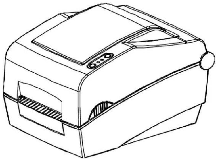
USER MANUAL SLP-T400EG/BEG Bixolon
User's Manual Label Printer
Rev. 1.05
SLP-TX400 / TX400E
SLP-TX403 / TX403E
natural_image
Line drawing of a mechanical device with no visible text or symbolsTable of Contents
※ Manual Information & Usage Precautions ....3
- Content Confirmation....7
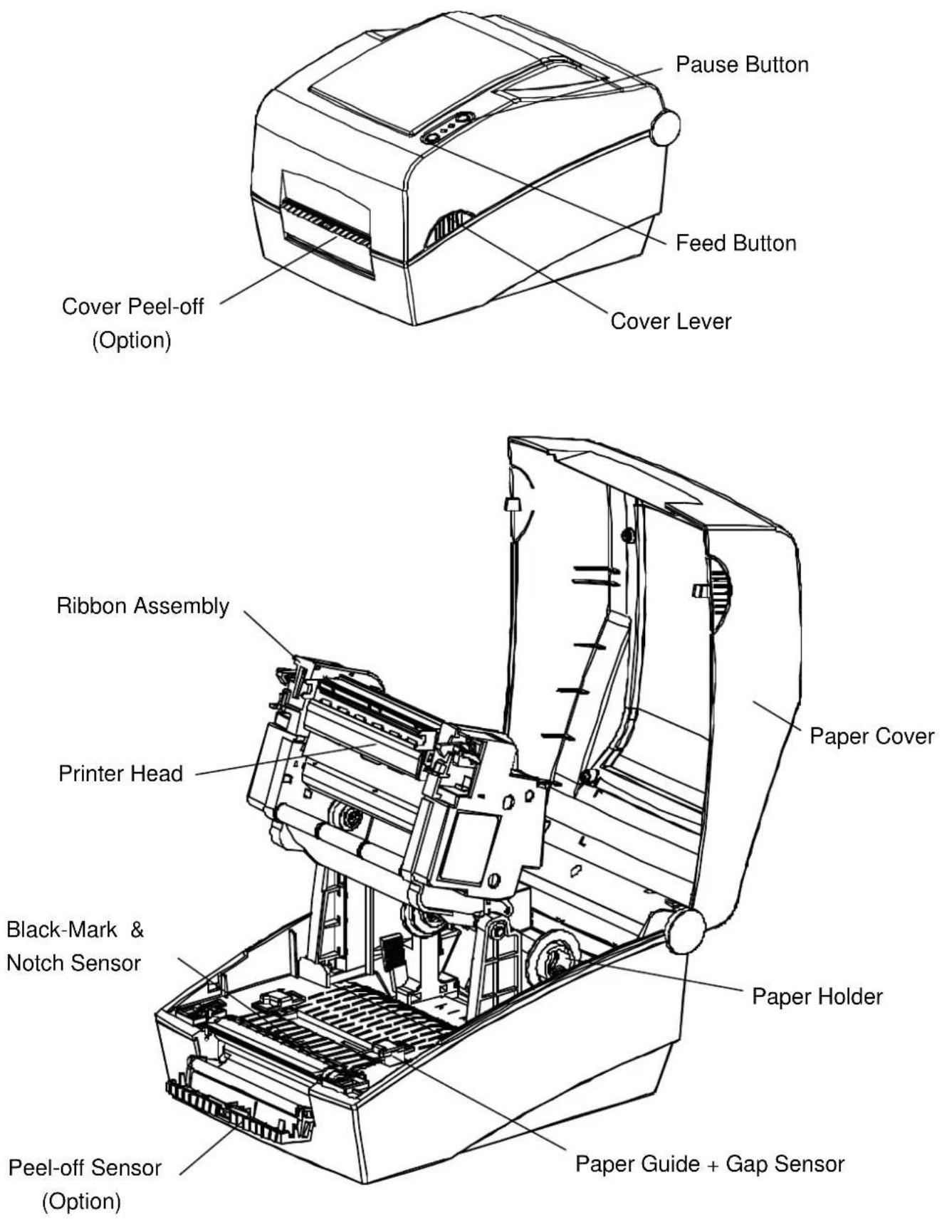
- Product Part Names......8
- Installation & Usage......10
3-1 Power Connection .... 10
3-2 Interface Cable Connection 11
3-3 Paper Installation....13
3-4 Ribbon Installation....14
3-5 LED Display....18
3-6 Test printing 20
-
Self-Test....21
-
Detailed features....22
5-1 Printer setting using utility program....22
5-2 Stand-alone Configuration Mode ....23
5-3 Pause/Cancel 24
5-4 Media Calibration....25
5-5 Smart Media Detection 26
5-6 Gap Sensor Auto Calibration Mode 26
5-7 Black Mark Sensor Auto Calibration Mode 27
5-8 Manual Calibration Mode....28
5-9 Cover Closing Mode 29
5-10 Data Dump Mode....29
5-11 Factory Reset....30
5-12 Firmware Download....30
5-13 The Peel-Off ....31
5-14 Using Fan-Fold Paper....33
5-15 Auto Cutter (SLP-TX40xC) 34
- Cleaning Head......35
6-1 Cleaning Head 35
6-2 Cleaning Sensors, Roller or/and Paper Path 36
- Appendix......37
7-1 Specifications....37
7-2 Label Types ....37
■ Manual Information
This user manual contains basic information for product usage as well as for emergency measures that may be required.
※ The following separate manuals provide more detailed content on various technological issues and areas.
1. Windows Driver Manual
This manual provides information on the installation instructions and main functions of the Windows Driver.
2. Unified Label Printer Utility Manual
This manual provides information on the usage of software for function selection of this product, operating condition modification, etc.
3. Programming (SLCS) Manual
This manual provides information on label printer commands.
4. True Font Downloader Manual
This manual provides information on the usage of the font downloader that can download True Fonts and facilitate their usage as Device Fonts.
5. Ethernet interface Manual
This manual provides information on the configuration and usage of Ethernet interface.
6. Label design program Manual
This manual provides information on the usage of the Windows PC program that can make labels by adding text, graphics, or barcodes at desired positions.
We at BIXOLON maintain ongoing efforts to enhance and upgrade the functions and quality of all our products. In following, product specifications and/or user manual content may be changed without prior notice.
■ Safety Precautions
In using the present appliance, please keep the following safety regulations in order to prevent any hazard or material damage.

WARNING
Violating following instructions can cause serious injury or death.
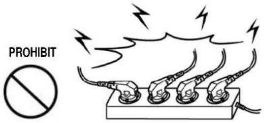
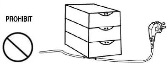
Do not plug several products in one multi-outlet.
• This can provoke over-heating and a fire.
- If the plug is wet or dirty, dry or wipe it before usage.
- If the plug does not fit perfectly with the outlet, do not plug in.
- Be sure to use only standardized multi-outlets.
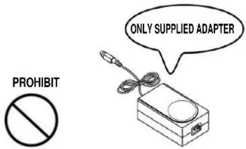
You must use only the supplied adapter.
- It is dangerous to use other adapters.
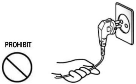
Do not pull the cable to unplug.
- This can damage the cable, which is the origin of a fire or a breakdown of the printer.
Keep the plastic bag out of children's reach.
• If not, a child may put the bag on his head.

Do not plug in or unplug with your hands wet.
- You can be electrocuted.

Do not bend the cable by force or leave it under any heavy object.
• A damaged cable can cause a fire.

CAUTION
Violating following instructions can cause slight wound or damage the appliance.
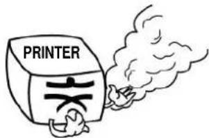
If you observe a strange smoke, odor or noise from the printer, unplug it before taking following measures.
- Switch off the printer and unplug the set from the mains.
• After the disappearance of the smoke, call your dealer to repair it.
TO UNPLUG

Keep the desiccant out of children's reach.
- If not, they may eat it.
PROHIBIT


natural_image
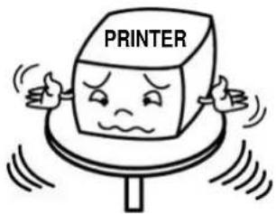
Cartoon illustration of a baby wearing a cap and holding a small object (no text or symbols)Install the printer on the stable surface.
- If the printer falls down, it can be broken and you can hurt yourself.
PROHIBIT

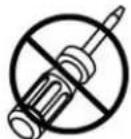
Use only approved accessories and do not try to disassemble, repair or remodel it for yourself.
- Call your dealer when you need these services.
- Do not touch the blade of auto cutter.
DISASSEMBLING
PROHIBITED

Do not let water or other foreign objects in the printer.
- If this happened, switch off and unplug the printer before calling your dealer.
PROHIBIT

Do not use the printer when it is out of order. This can cause a fire or an electrocution.
- Switch off and unplug the printer before calling your dealer.
TO UNPLUG


■ Other Precautions
The copyright for this user manual and various other manuals is property of the BIXOLON Co., Ltd. Any copying or conversion into electronic firm and saving of this material without the express written permission of BIXOLON Co., Ltd. is strictly prohibited.
Use of the information contained in this manual is not subject to any patent liability. This manual has been prepared with utmost care and attention to detail but may contain certain errors and/or omissions.
BIXOLON Co., Ltd. is not legally liable for any damages resulting from the use of the information in this manual.
BIXOLON Co., Ltd. and its affiliates are not legally liable (United States excluded) for any damages, loss, costs, and/or expenses that result from the breakdown, malfunction, and/or misuse of the product due to violation or neglect of the operation and maintenance information and instructions provided by the BIXOLON Co., Ltd., as well as from the unauthorized alteration, repair, and/or modification of the product by the user and/or third party.
BIXOLON Co., Ltd. is not legally liable for any damages and/or issues resulting from the use of options and/or parts that are not authentic BIXOLON products or authorized products.
WARNING
Use of an unprotected interface cable with this printer conflicts with EMC standards. Users should only use cables approved by BIXOLON.
■ WEEE (Waste Electrical and Electric Equipment)
This mark shown on the product or its literature indicates that the corresponding item should not be discarded at the end of its working life with other household waste. To prevent possible harm to the environment or human health from uncontrolled waste disposal, please separate marked items from other types of waste and recycle them responsibly to promote the sustained reuse of material resources. Household users should contact either the retailer where they purchased this product, or their local government office for details of where and how they can conduct environmentally safe recycling of such items. Commercial users should contact their suppliers and check the terms and conditions of purchase contracts. This product should not be combined with other commercial waste for disposal.
■ Rating Label Symbol Information

DC (Direct current)

1. Content Confirmation
The following items should all be contained in the printer package.
Contact the dealer from which the purchase was made if any item is damaged and/or missing.
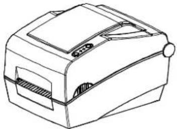
natural_image
Line drawing of a mechanical device with no visible text or symbolsSLP-TX400/TX403
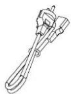
Power Cord
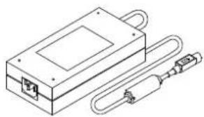
natural_image
Technical line drawing of a rectangular electronic device with a U-shaped connector and a coiled cable (no text or symbols)AC Adapter
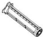
Holder Ribbon (2ea)
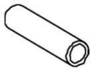
Core
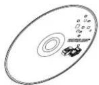
CD
User's Manual
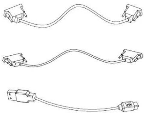
※ Optional items
natural_image
Three line drawings of cable connectors with no text or symbolsRS-232C(Serial) Cable
IEEE1284(Parallel) Cable
USB Cable
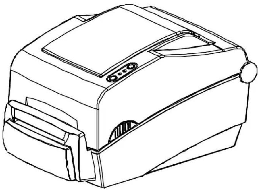
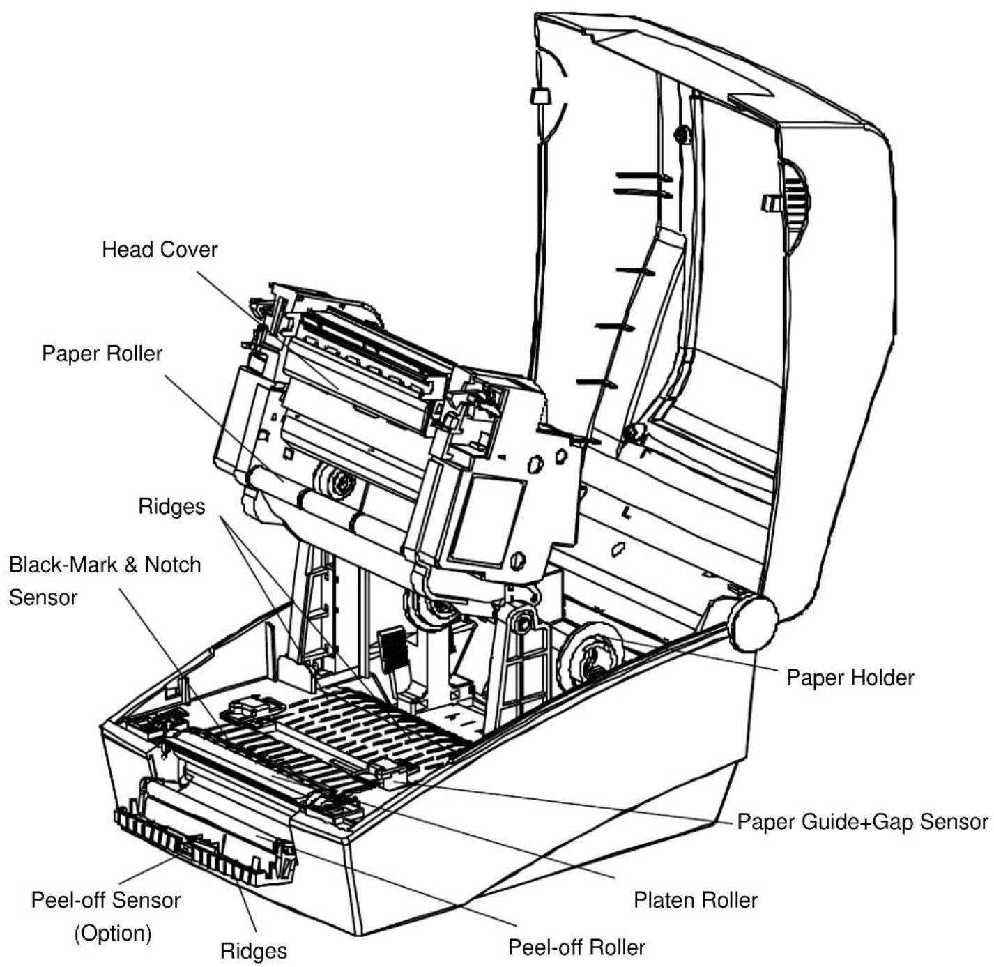
2. Product Part Names
3. Installation & Usage
3-1 Power Connection
Connect power to the printer as shown below.
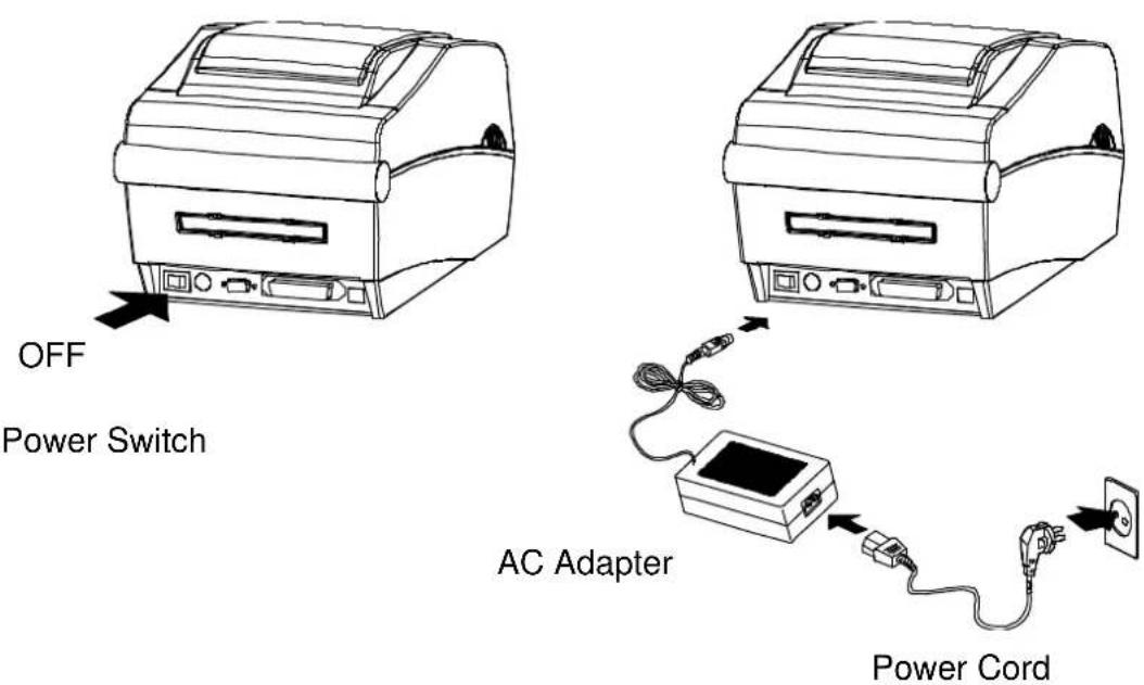
1) Turn off the printer power switch.
2) Check to see that the AC adapter voltage matches that of the power source.
3) Connect the AC adapter jack to the printer power connector.
4) Connect the power cord to the AC adapter.
5) Connect the power cord to a power source/outlet.
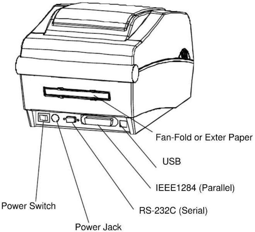
3-2 Interface Cable Connection
3-2-1 Standard Model
Connect the interface cable as shown below.
This printer supports the following communications interface standards.
- RS-232C(Serial) Cable
- IEEE1284(Parallel) Cable
- USB B-Type Cable
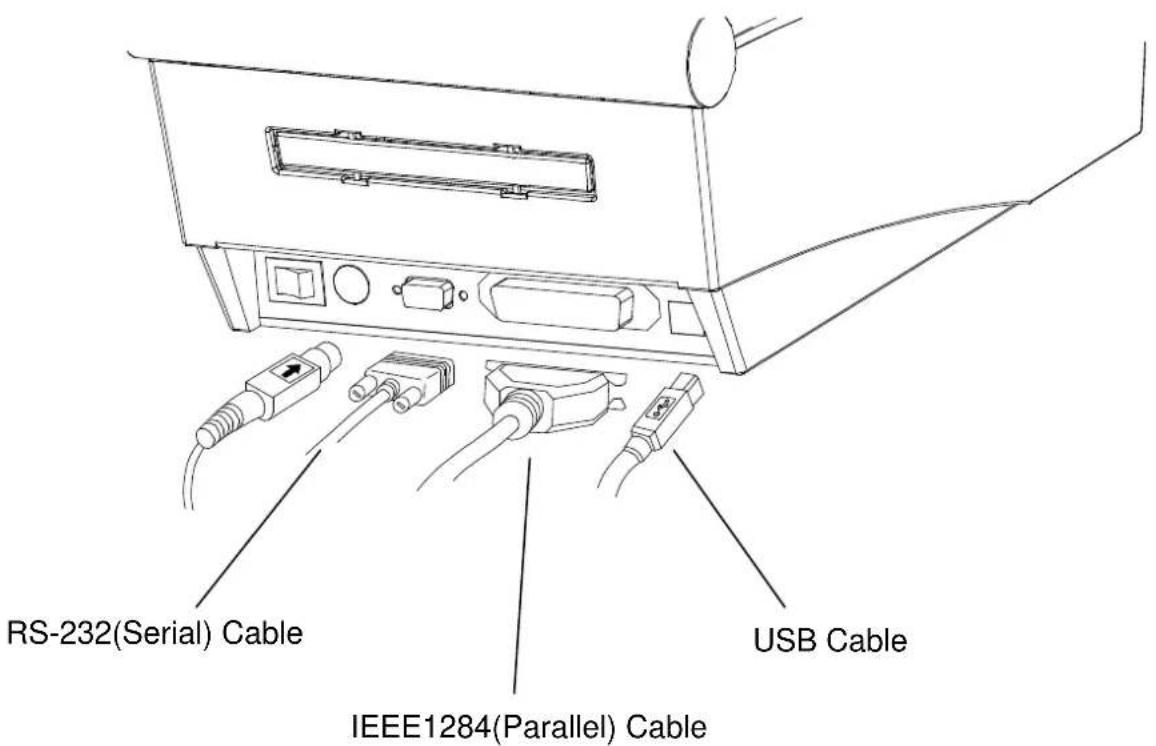
1) Turn off the power switch.
2) Connect the communication cable to the printer communication port to be used.
- Connect the RS-232C(Serial) Cable to the SERIAL port.
and tighten the screw on both sides.
- Connect the IEEE1284(Parallel) Cable to the PARALLEL port.
and fasten the clips on both sides.
- Connect USB B-Type cable to the USB port.
3-2-2 Ethernet Model(SLP-TX40xE)
Connect the interface cable as shown below.
This printer supports the following communications interface standards.
- RS-232C(Serial) Cable
- LAN(Ethernet) Cable
- USB A-Type(WLAN Dongle)
- USB B-Type Cable
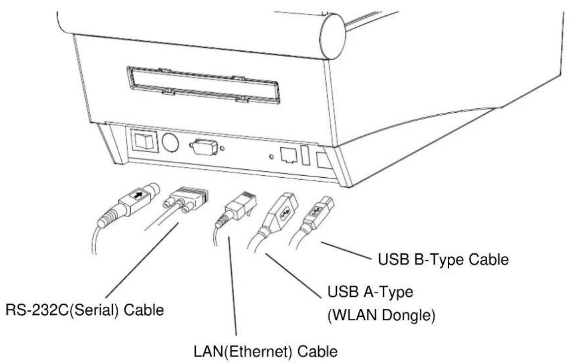
1) Turn off the power switch.
2) Connect the communication cable to the printer communication port to be used.
- Connect the RS-232C(Serial) Cable to the SERIAL port. and tighten the screw on both sides.
- Connect the LAN(Ethernet) Cable to the ETHERNET port.
- Connect USB A-Type(WLAN Dongle) to the HOST port.
- Connect USB B-Type Cable to the USB port.
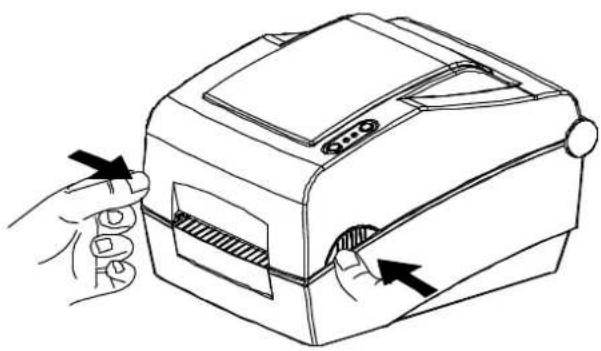
3-3 Paper Installation
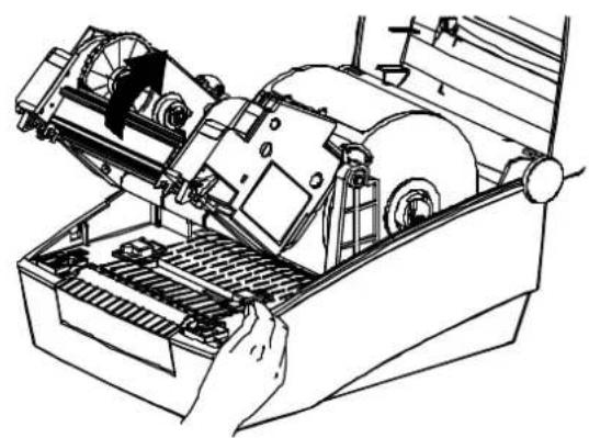
1) Open the Paper Cover.
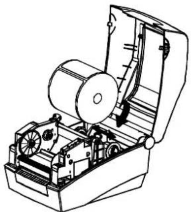
natural_image
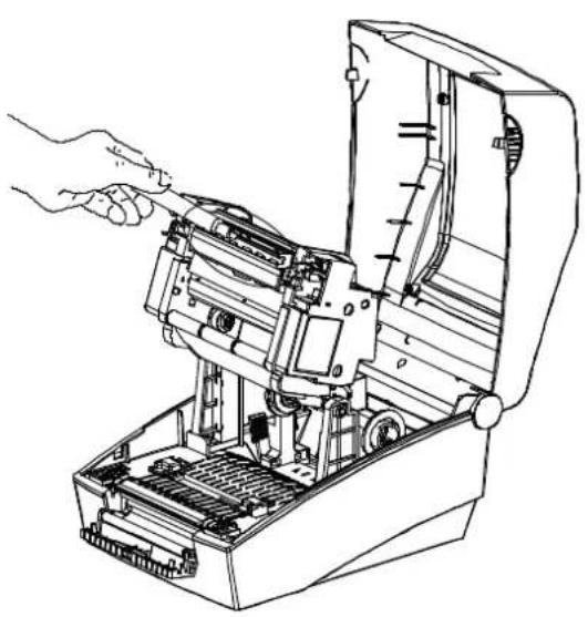
Line drawing of a hand inserting a device into a device with arrows indicating the process (no text or symbols present)3) Open the Ribbon Assembly and spread the paper guide.
2) Spread the paper holder and insert paper as shown.
natural_image
Technical line drawing of an open mechanical device with gears and a cylindrical component (no text or symbols)4) Feed the paper between the Paper Guide on both sides.
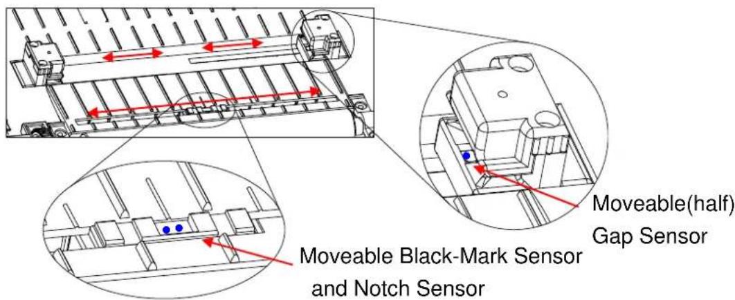
natural_image
Technical line drawing of a mechanical assembly with gears and rollers (no text or symbols)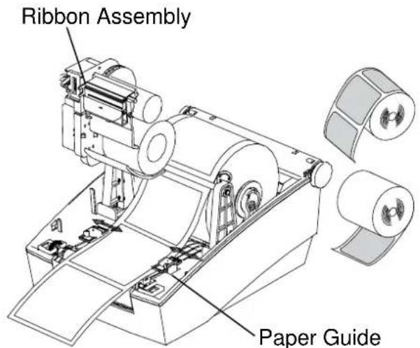
5) After Installation the paper, manually set the sensor(Gap & Black-Mark) and Paper Guide to the correct position.
6) Close the Ribbon Assembly until a click sound is heard, close the Paper Cover.
3-4 Ribbon Installation
3-4-1 Type of Ribbon
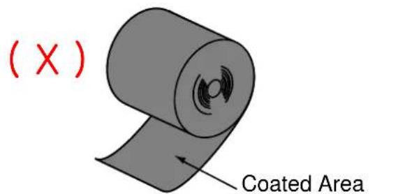
1) Type by Film Coating Location
- Take note before ribbon purchase that only ribbons facing outward can be used.
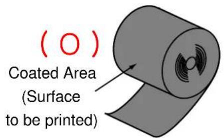
Outside Ribbon
(Surface to be printed)
Inside Ribbon
※ Note
- Follow the procedure described below to determine the coating surface of the ribbon.
- Ribbon test using adhesive material
- Perform contact test in order to determine which side is coated if there are useable labels.
- Complete the following steps to carry out the contact test
- Remove the liner from the label
- Put a piece of adhesive surface of the label on the outer/inner surface of the ribbon, and apply pressure.
- Remove the label from the ribbon
- Check whether adhesive surface of the label is stained by black ink ribbon.
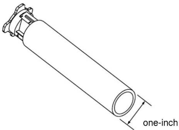
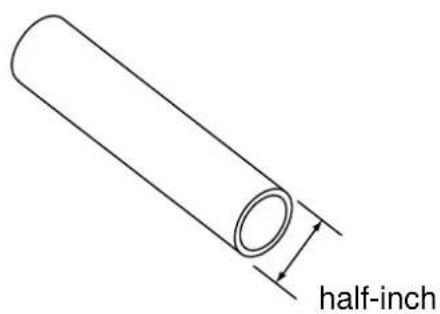
2) Type by Roll Core
- This printer can be used to one-inch or half-inch core ribbon.
- For a 1-inch core, a roll core must be used.
- The holder ribbon and roll core of the fully used ribbon must be reused.
Do not discard.
3-4-2 Inserting a One-Inch Core Ribbon
1) Insert the Holder ribbon into the core and ribbon. (keep note of ribbon printing direction)
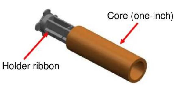
2) Open the ribbon assembly and insert the ribbon and core by pushing from left to right.
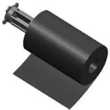
natural_image
3D rendered image of a black cylindrical mechanical component with a protruding shaft (no text or symbols visible)3) Apply tape to the coiling portion of the ribbon.
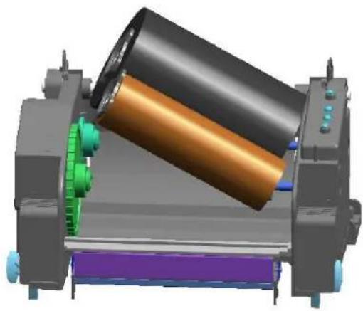
natural_image
3D mechanical assembly diagram showing a cylindrical component with colored components and mounting brackets (no text or symbols visible)4) Press the Close area to shut the ribbon assembly.
3-4-3 Inserting a Half-Inch Core Ribbon
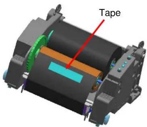
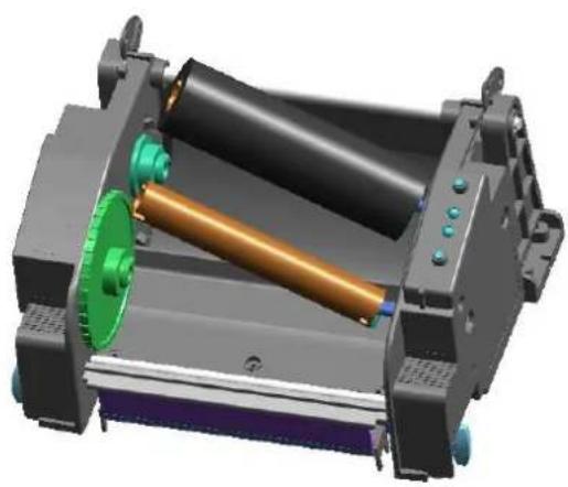
1) Open the ribbon assembly and insert the ribbon and core by pushing from left to right. (keep note of ribbon printing direction)
2) Apply tape to the coiling portion of the ribbon.
natural_image
3D rendering of a mechanical assembly with a cylindrical roller and green component (no text or symbols visible)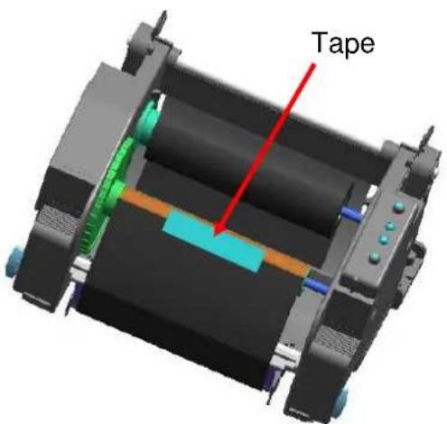
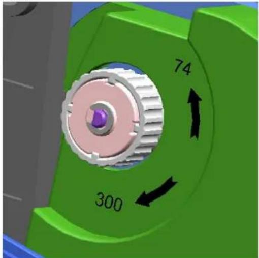
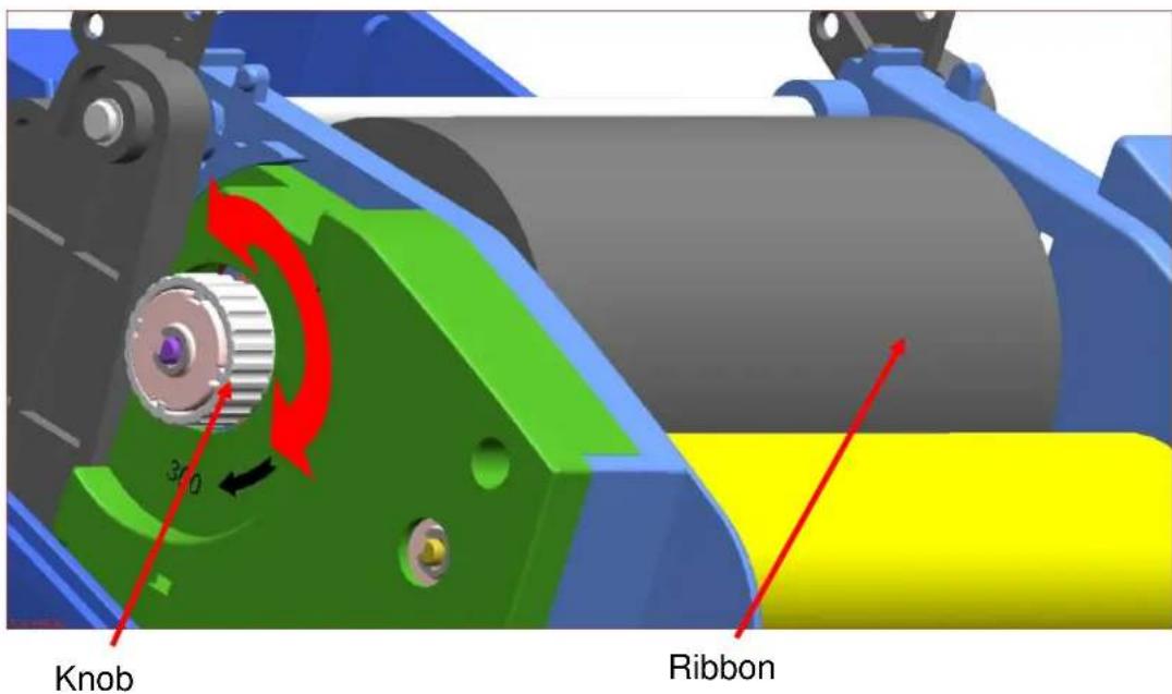
3-4-4 Knob Adjustment by Ribbon Length
Ribbon lengths of 74m, 100m (0.5" core), and 300m (1" core) can all be used with product. Adjust the knob accurately according to the ribbon length (74 \~ 300 m).
Exercise care as print quality and operation can be affected.
- The product is shipped with a default setting for a ribbon length of 300m (1" core). To use a 74m (0.5" core) ribbon, adjust (rotate) the knob in the direction of 74m prior to use.
- When the cover is outside the knob as shown in the image, the ribbon length is set to 74m. If the cover is inside the knob as shown in Image B, the ribbon length is set to 300m.
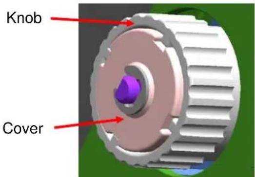
Image-A (74m)
natural_image
Close-up of a green mechanical gear with a 300-degree angle and 74-degree rotation arrow (no text or symbols beyond measurement labels)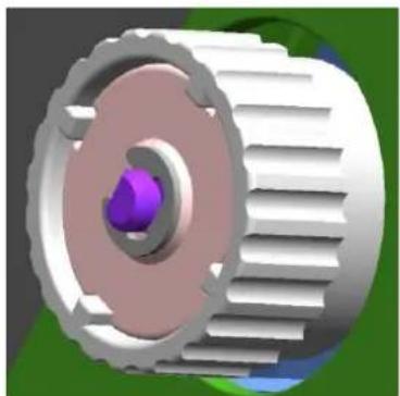
natural_image
3D rendered mechanical gear assembly with central purple component and mesh texture (no text or symbols)Image -B (300m)
Knob Adjustment
- Grasp the ribbon while it is fitted and rotate the knob as shown in the image.
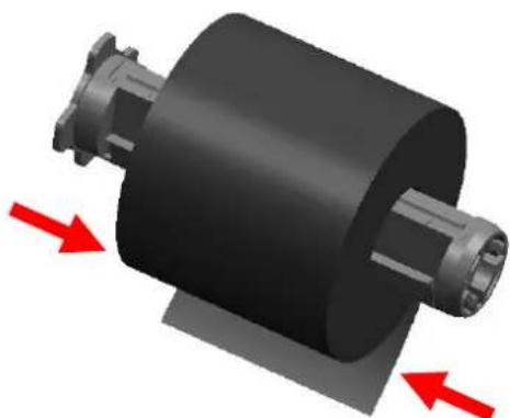
3-4-5 Narrow Ribbon Installation
When using ribbons of widths of 110mm or lower, install in a centered position on the holder ribbon.
natural_image
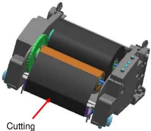
3D rendering of a cylindrical mechanical component with red directional arrows indicating force or movement (no text or symbols)3-4-6 Ribbon Removal
1) Use a knife or other sharp-edged object to cut the ribbon. (Take care not to injure hands)
2) Open the ribbon assembly and remove the ribbon and core by pushing from left to right.
3) Detach the ribbon holder from the ribbon and core.
natural_image
3D mechanical assembly diagram showing a cylindrical component with internal components and a labeled cutting point (no text or symbols beyond the label)3-4-7 Ribbon Sensor Activation
Ribbon detection sensor is disabled by default factory settings. Check the settings related to ribbon detection sensor if printing does not stop when the printer is out of ribbon or ribbon is broken.
* Ribbon detection sensor can be enabled by command control. And default setting can be changed by Unified Label Utility.
※ CAUTION
-
When replacing a ribbon, keep affixed the core of the fully used ribbon to the ribbon coiling portion on the other side and do not discard as its use is required.
-
As the ribbon holder is required for continuous use, make sure not to misplace it.
3-5 LED Display

3-5-1 Button Operations
| Printer state before operation | Button | Operation procedure | Printer operation mode | |
| Feed/ Cancel | Pause | |||
| Power OFF | Press | - | ·Apply power while pressing the button.·Hold the button for about five seconds. | Self-test Printing Mode. |
| Print Standby | Press | - | ·Press the button softly and release it immediately | Feed Mode |
| Print Standby | - | Press | ·Press the button for two seconds and continue to hold | Stand-alone configuration Mode |
| During printing | Press | - | ·Press the button softly and release it immediately | Print Cancel Mode |
| During printing | - | Press | ·Press the button softly and release it immediately | Print Pause Mode |
3-5-2 LED indicator for various printer statuses
| LED 1 | LED 2 | Printer Status | |||
| Color | Status | Color | Status | ||
| Green | On | Green | On | Print standby mode | Print standby mode |
| Red | On | Red | On | Error mode | Ribbon is not detected |
| Red | On | Orange | On | Error mode | Paper jam (gap/black mark is not recognized) |
| Red | On | Green | Blink | Error mode | Printer head overheating |
| Red | On | Red | Blink | Error mode | Cover open |
| Red | On | Orange | Blink | Error mode | No paper |
| Red | On | - | Off | Error mode | Media calibration failure |
| Red | Blink | Red | Blink | Error mode | Auto-Cutter error |
| Orange | On | Orange | On | Mode switching notification | Mode switching notification |
| Green | Blink | Red | On | Wait for input | Print is paused temporarily. Wait for button input |
| Green | Blink | Green | Blink | Wait for input | Cover Close Mode. Wait for button input |
| Green | On | Red | Blink | Wait for input | Print Cancel Mode. Wait for button input |
3-6 Test printing
3-6-1 Printing using Windows driver
1) Install the Windows driver. Refer to the "Windows driver manual" in the CD for the installation procedure.
2) Set the "port" of Windows driver to the appropriate interface to be used. Refer to the "Ethernet interface user's manual" in the CD when using Ethernet interface.
3) Print the test page using the "Print test page" function of Windows driver.
3-6-2 Printing using label design program
- The label design program is included in the separate CD.
1) Install the label design program.
2) Refer to the "Label Design Program Manual" included in the CD and set the interface.
3) Print the test page after designing a label.
4. Self-Test
The self-test checks whether the printer has any problems.
- Firmware version, printer configuration information, printing quality checking pattern, and peripheral configuration information, etc.
Users cannot perform this procedure if using the printer's label peel-off option. If the printer does not function properly, contact an authorized dealer.
The self-test checks the following;
1) Make sure that the paper roll has been installed properly.
2) Turn on the power while pressing the feed button then self-test will begin. (Hold the button for about five seconds)
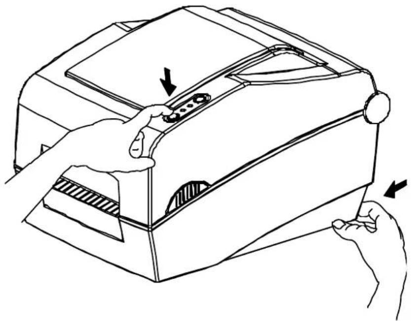
natural_image
Line drawing of a hand operating a device with arrows indicating process steps (no text or symbols)5. Detailed features
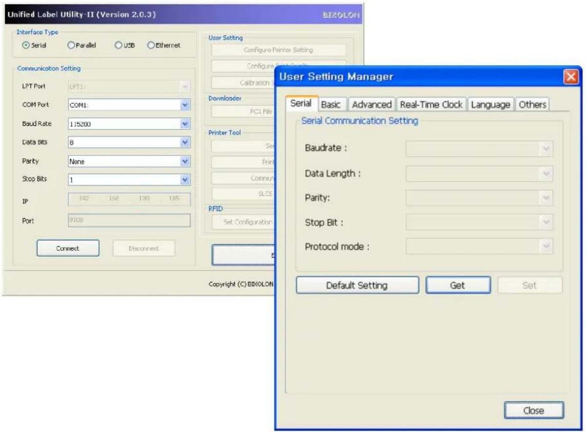
5-1 Printer setting using utility program
Various printer settings can be changed using the utility program (Unified Label Utility).
Functions that can be used with the utility program are as follows.
1) Serial communication settings
Handshake, Stop bit, Data bit, Parity, and Baud rate can be configured.
2) Basic printer settings
Paper size, printing speed and density, paper type, and use of ribbon can be configured.
3) Language setting
Code page can be configured.
4) Media sensor manual calibration function
This function can be used to detect special type or special material paper that is not detected through automatic calibration function. Refer to M Manual Calibration page for more details
5) Other functions for printer test are also provided.
Refer to the United Label Printer Utility Manual contained in the CD for more detailed information.
5-2 Stand-alone Configuration Mode
Various modes can be executed using buttons and LED only.
5-2-1 How to start stand-alone configuration mode
- The printer mode is set to Printer Setting Mode when the Pause button is pressed for two seconds while in Print Standby Mode.
- Both LEDs will change to orange color and the printer will be set to Stand-along Configuration Mode.
- When the printer enters into this mode, the status of LED 1 and LED 2 are changed sequentially.
- When the Feed button is pressed at specific LED color combination, the corresponding printer operation will be selected.
5-2-2 List of supported functions
| Sequence number | LED 1 | LED 2 | Printer operation | ||
| Color | Status | Color | Status | ||
| 1 | Green | On | Green | Blink four times | Print Configuration Info. |
| 2 | Orange | Blink four times | Print File List | ||
| 3 | Red | Blink four times | Factory Reset | ||
| 4 | Orange | On | Green | Blink four times | Gap Sensor Auto Calibration |
| 5 | Orange | Blink four times | B/M Sensor Auto Calibration | ||
| 6 | Red | Blink four times | Data Dump Mode | ||
| 7 | Red | On | Green | Blink four times | - |
| 8 | Orange | Blink four times | - | ||
| 9 | Red | Blink four times | - | ||
5-3 Pause/Cancel
During multiple-page print jobs, the Pause and Cancel button can be used to temporarily cease printing and cancel the print job altogether, respectively.
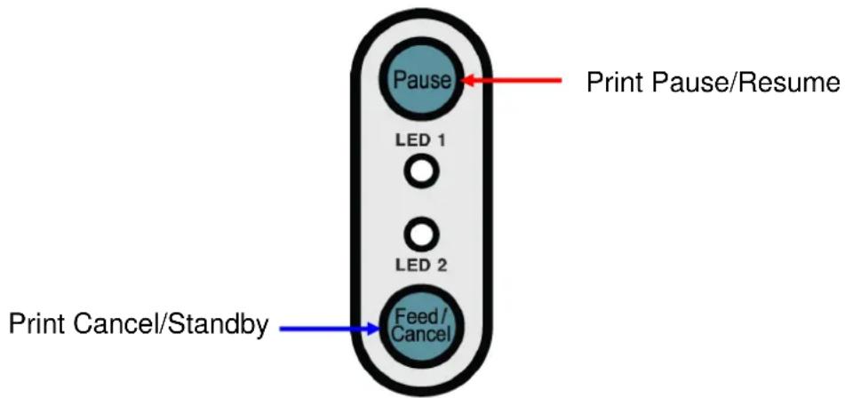
5-3-1 Pause/Resume Function
1) When printing labels, pressing the Pause button
2) The printer will pause after finishing the current label printing and the status of LED will be as follows.
- LED 1: Green Blink
- LED 2: Red On
3) While the print job is paused, press the Pause button again to resume printing.
5-3-2 Print Cancellation
1) During label printing and/or pause mode, pressing the Cancel button enters the print cancellation mode.
2) The following processes occur in the print cancellation mode.
- All label printing cancelled
- All data received in the printer communications buffer deleted.
- All received data deleted.
3) The LED Status in the print cancellation mode can be as follows.
- LED 1: Green On
- LED 2: Red Blinking
4) While in the print cancellation mode, press the Cancel button again to return to print standby mode.
5-4 Media Calibration
This printer has been designed to recognize the gaps with most print papers, but sometimes it may not recognize the gap and keep feeding paper if a special type of paper is used. In this case, run Auto Calibration function so that the printer can recognize the gap. BIXOLON printer provides various media calibration methods in order to accommodate various special paper types.
5-4-1 About media calibration
- This function is for adjusting the sensitivity of the paper detection sensor for accurate printing position control and measuring actual length of paper.
- Sensor sensitivity adjustment
- The purpose is to detect the identifier (gap/black mark/groove) of installed label printer
• Paper length measurement
- Accurate length is required to rotate the printing orientation.
- The purpose is to detect the change of paper type.
5-4-2 When is media calibration required?
- When the printer is installed first time
- When the newly installed paper is a different paper type
- When printer position is not accurate or printer does not stop in the right position
5-4-3 How to perform media calibration
- The following four methods of media calibration can be used depending on the conditions.
- Smart Media Detection
- Gap Sensor Auto Calibration Mode
- Black Mark Sensor Auto Calibration Mode
- Manual Calibration Mode
- Why are several calibration methods provided?
- Multiple labels should be scanned for media calibration and more accurate sensitivity calibration can be performed when more labels are scanned.
- The number of labels to scan for sensor sensitivity adjustment depends on various conditions such as label paper material, color, surface status, thickness, gap length, pre-printed pattern, etc.
- Four different media calibration modes are provided for compromise between prevention of excessive use of paper and accuracy of sensor sensitivity adjustment.
- Smart media detection mode that allows for adjustment of sensitivity with minimum amount of scanning should be good enough for most cases with general labels.
- Try various methods in order of Smart Media Detection → Gap Sensor Automatic Calibration → Black Mark Sensor Automatic Calibration → Manual Calibration Mode.
5-5 Smart Media Detection
- Printer executes this function when necessary without user input and media configuration can be completed with Smart Media Detection function for most print papers.
- Papers with gap and black mark can be identified without separate settings.
- 3 \~ 5 pages of labels will be used depending on the type of paper.
-
Smart Media Detection function is executed in the followings cases
-
When the printer is installed first time, it is executed through Feed button or print command.
- When change paper length is detected during feeding or printing.
- When the paper type entered by command is different from the configured paper type.
- After reset with factory settings
- Smart Media Detection function will be turned off after setting the sensor sensitivity using Automatic Calibration Mode or Manual Media Calibration mode, and it will be enabled again after resetting the printer with factory settings.
5-6 Gap Sensor Auto Calibration Mode
Use this mode when paper is not detected correctly with Smart Media Detection function.
Printer feeds paper and calibrates Gap Sensor automatically.
The printer will enter error mode if paper detection fails after feeding up to 1 meter of paper. Error mode can be released by opening and closing the cover.
Use Manual Calibration Mode if paper detection fails in this mode.
Smart Media Detection will be disabled if paper detection is successful in this mode.
5-6-1 Procedure to run the calibration
- Press the Feed button at 4th LED sequence in 5-2-2 (LED 1 Orange / LED 2 Green – Blink four times) to start Gap Sensor Automatic Calibration Mode.
5-7 Black Mark Sensor Auto Calibration Mode
Use this mode when paper is not detected correctly with Smart Media Detection function.
Printer feeds paper and calibrates Black Mark Sensor automatically.
The printer will enter error mode if paper detection fails after feeding up to 1 meter of paper. Error mode can be released by opening and closing the cover.
Use Manual Calibration Mode if paper detection fails in this mode.
Smart Media Detection will be disabled if paper detection is successful in this mode.
5-7-1 Procedure to run calibration
- Press the Feed button at 5th LED sequence in 5-2-2 (LED 1 Orange / LED 2 Orange – Blink four times) to start Black Mark Sensor Automatic Calibration Mode.
5-8 Manual Calibration Mode
Manual-calibration of media detection can be used when the printer cannot detect a media gap (or black mark) even after auto-calibration has been executed.
Users can calibrate sensor parameters in detail by using the utility program provided by the manufacturer.
The utility can be obtained from the enclosed CD or downloaded from the Internet via the BIXOLON website www.bixolon.com
Please make sure the printer is connected and execute the utility program. Please the Calibration Setting Manager Button after setting the interface type.
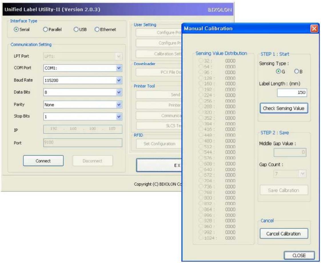
1) Select the sensing type and input the label length by millimeter and click on "Check Sensing Value" tap. Then printer starts to calibrate.
2) The scanned values will appear on the Utility.
3) Optimal sensing values will appear in black bold letters on the left of the utility screen and select one of the values and click on "Save Calibration"
4) If chosen value does not work properly, please try the other values among the black bold letters.
5) To go back to the initial value, please click on "Cancel Calibration"
5-9 Cover Closing Mode
1. About Cover Closing Mode
- The printed area may become out of range of paper if the paper is not in the accurate printing position when the cover is opened and closed.
- The printer is put to Cover Closing Mode instead of Print Standby Mode when the cover is closed in order to prevent this problem, and it waits for user input.
- The status of LEDS are as follows in this mode.
- LED 1: Green Blink
- LED 2: Green Blink
- The data received during Cover Close Mode are not printed, and they are printed automatically when the printer recovers to the Print Standby Mode.
2. How to switch the printer from Cover Close Mode to Print Standby Mode
- Press the Pause button to switch to Print Standby Mode without feeding any paper.
- Press the Feed button to feed one page to align the paper position and switch to the Print Standby Mode.
5-10 Data Dump Mode
This function can be used to diagnose the communication issues when the printing does not work correctly.
In this mode, the received data are not analyzed and printed, instead they are dumped in hex format without processing.
Turn the printer off and on to recover to the Print Standby Mode.
5-10-1 How to start Data Dump Mode
1) Press the Pause button for two seconds during Print Standby Mode.
2) Both LEDs will change to orange color and the printer will be set to Stand-along Configuration Mode.
3) Press the Feed button at the sixth LED sequence in 5-2-2 (LED 1 Orange / LED 2 Red - 4 times Blink) to enable Data Dump Mode.
5-11 Factory Reset
This function is used to reset the printer settings to factory default settings.
5-11-1 How to reset the printer
1) Press the Pause button for two seconds during Print Standby Mode.
2) Both LEDs will change to orange color and the printer will be set to Stand-along Configuration Mode.
3) Press the Feed button at the third LED sequence in 5-2-2 (LED 1 Green / LED 2 Red – 4 times Blink) to reset the printer to factory settings, and Smart Media Detection function will be executed.
5-12 Firmware Download
Refer to the "Firmware download manual" in the CD for the installation procedure.
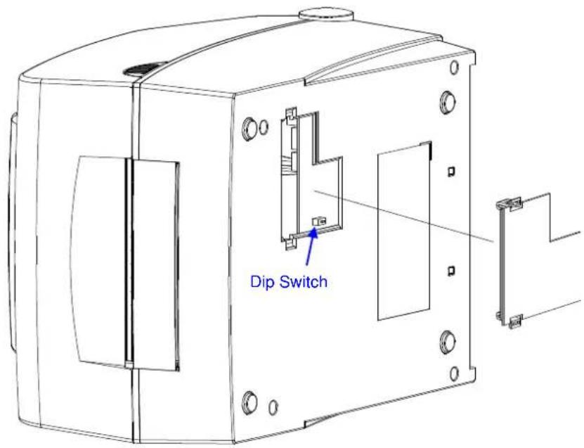
※ CAUTION
Make sure if the dip cover is closed prior to operating.
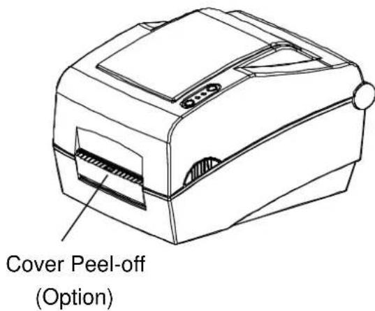
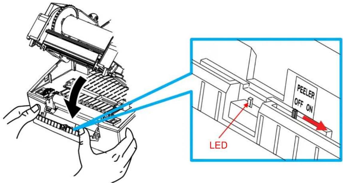
5-13 The Peel-Off
As a function that is used to peel-off labels, it is used only with label paper.
(After adjusting the peeler switch, power must be turned off and on in order for the operation to be acknowledged.)
1) Open the paper cover.
2) Open the Ribbon Assembly.
3) Open the label peel-off cover and set the peeler switch to the ON position.
- Check to see that the LED has turned on.
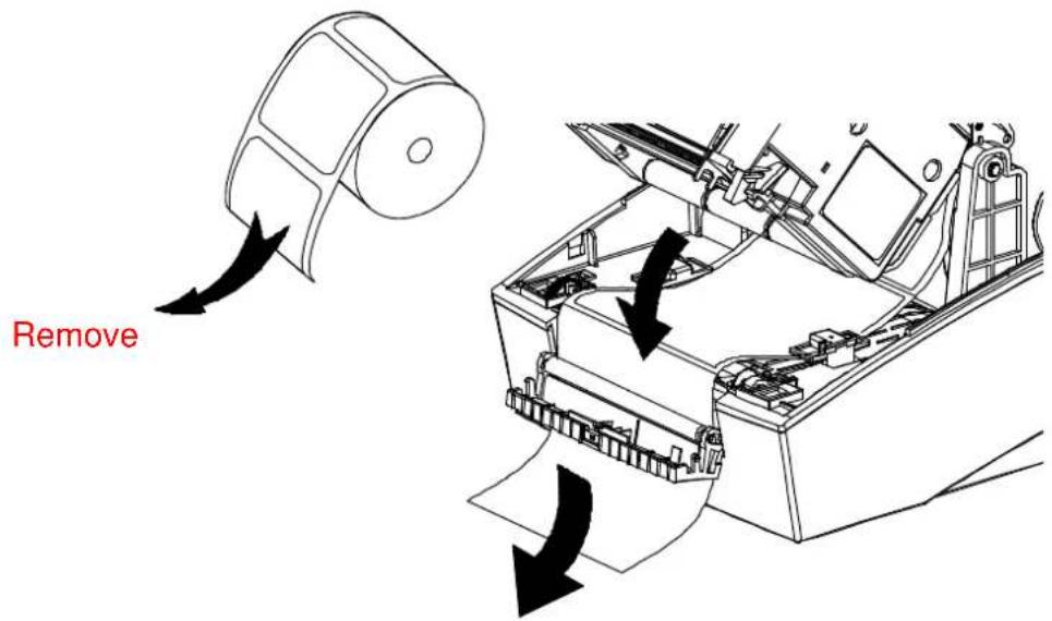
4) Remove one sheet of the label paper, and insert the paper as shown in the image below.
- Prior to removing a label, the peeler switch must be set to the ON position.
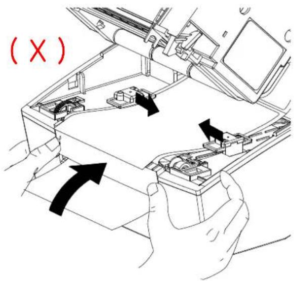
5) Adjust the paper guides and close the label peel-off cover.
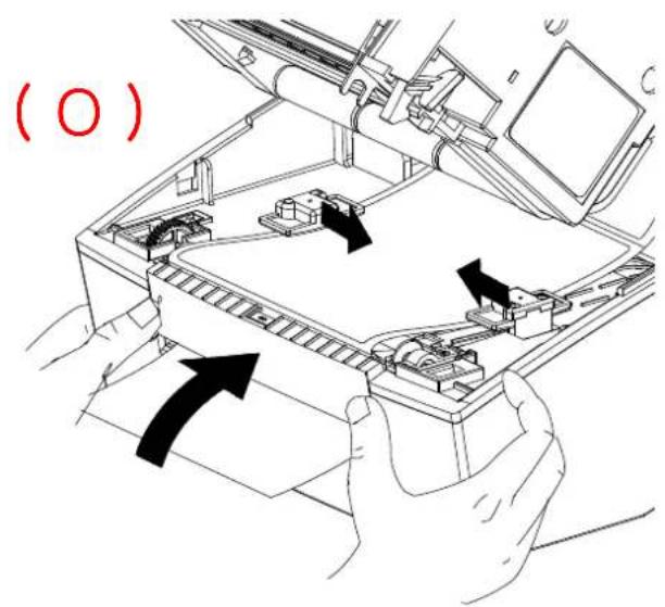
6) Close the Ribbon Assembly until a click sound is heard, close the Paper Cover.
7) Turn the printer off and on.
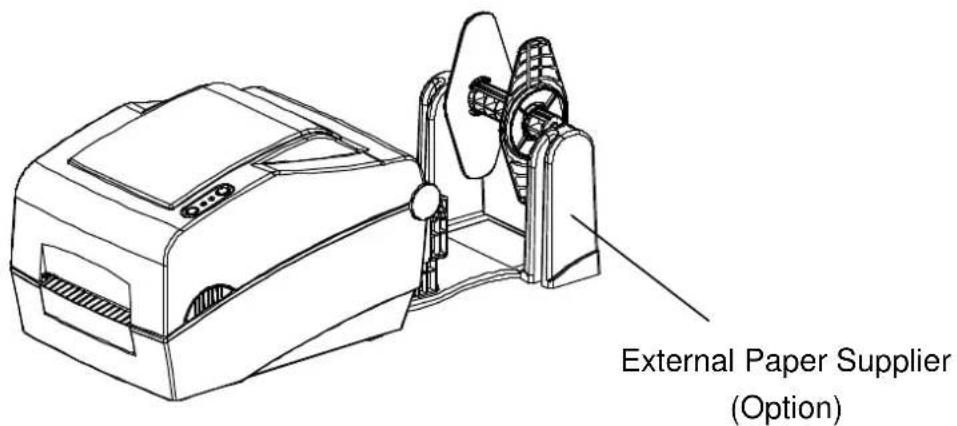
5-14 Using Fan-Fold Paper
Supplying paper to the printer externally is done as follows.
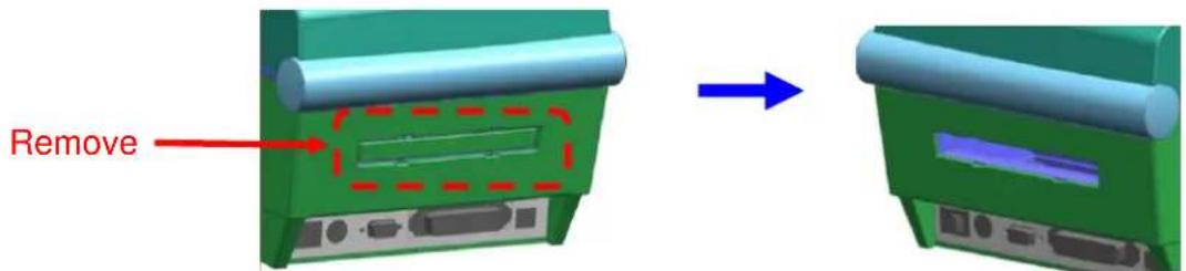
5-14-1 Printer Preparation
Remove the rear paper supply cover on the back side of the printer with a knife or other cutting instrument.
※ CAUTION
- Take care not to injure the hands and/or any other part of the body when performing this step.
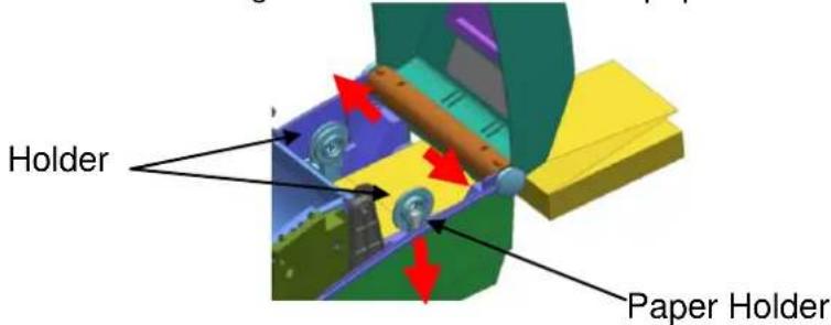
5-14-2 When Using Pan-Fold Paper
1) Insert the paper at the rear of the printer using the slot and guides.
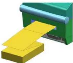
natural_image
3D illustration of a printer emitting yellow paper onto a green cover (no text or symbols)2) Adjust the holder and guides to the width of the paper.
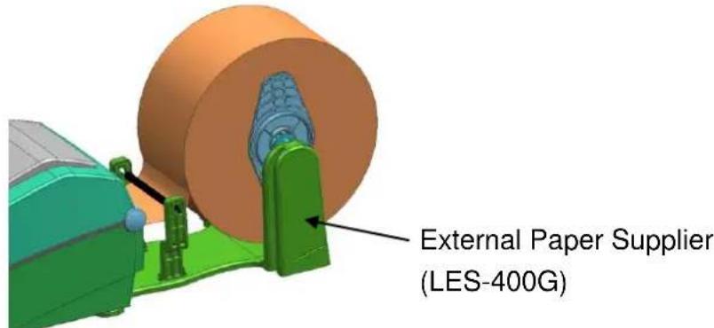
5-14-3 When using large-capacity paper roll (option)
※ install the paper in the same way as pan-fold paper.
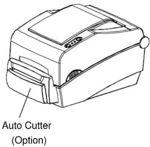
5-15 Auto Cutter (SLP-TX40xC)
For auto paper cutting, products equipped with auto cutter are available.
In factory setting, the auto cutter is attached.
Auto-Cutter can be controlled by command. And default setting can be changed by Unified Label Utility.
※ The paper installation method is the same as paper with no auto cutter.
natural_image
Line drawing of a toaster oven with front panel and side slots (no text or symbols)6. Cleaning Head
Printing quality might be degraded by dust, foreign substance, adhesive substance, or other pollution materials stuck in the printer head or inside the printer.
When dirty, clean the print head as follows:
※ CAUTION
- Make sure to turn the printer power off prior to cleaning.
- As the print head gets very hot during printing, if intending to clean the print head, turn the printer power off and wait approximately 2\~3 minute before commencement.
- When cleaning the print head, take care not to touch the heated portion of the print head.
→ Printer Head is susceptible to damage from static electricity, etc. - Take care not to allow the print head to become scratched and/or damaged in any way.
6-1 Cleaning Head
1) Open the paper cover and Ribbon Assembly and then use the cleaning pen to clean the head in the direction from the center of the head to the edges.
2) After cleaning the head, do not use the printer until the alcohol used for cleaning evaporates completely (1\~2 min) and the printer has completely dried.
※ Perform the cleaning process each time the paper roll is replaced to prevent print quality deterioration.
natural_image
Line drawing of a mechanical device with a hand operating it, showing internal components and no text or symbols.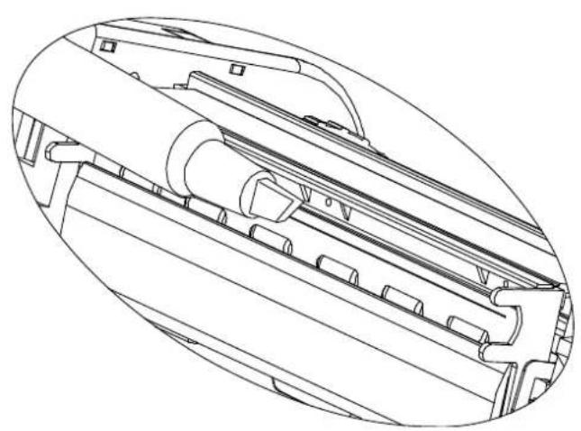
natural_image
Technical line drawing of a mechanical component with internal channels and mounting brackets (no text or symbols)6-2 Cleaning Sensors, Roller or/and Paper Path
1) Open the paper cover and ribbon assembly, and remove the paper and ribbon.
2) Remove any dust or foreign substance using dry cloth or cotton swab.
3) Soak the cloth or cotton swab in alcohol for medical use and use it to remove adhesive foreign substances or other pollution materials.
4) After cleaning the parts, do not use the printer until the alcohol evaporates completely (1\~2 min) and the printer has completely dried
※ Clean the parts when there is a degradation of performance in printing quality or paper detection.
Rev. 1.05
7. Appendix
7-1 Specifications
| Item | Description | |
| Printer | Printing Method | Thermal Transfer / Direct Thermal Printing |
| Dot Density | SLP-TX400 : 203 dpi (8 dot/mm)SLP-TX403 : 300 dpi (11.8 dot/mm) | |
| Printing Width | SLP-TX400 : Max. 108 mmSLP-TX403 : Max. 105.7 mm | |
| Printing Speed | SLP-TX400: Max. 178 mm/sec (Max. 7ips)SLP-TX403: Max. 127 mm/sec (Max. 5ips) | |
| Paper | Width | 25 ~ 116 mm |
| Roll | Max 130mm | |
| Core | 25.4~38.1mm (1~1.5") | |
| Ribbon | Length / Width | Max 300m / 33 ~ 110mm(1.3~4.3") |
| Type(Outside) | Wax, Wax/Resin, Resin | |
| Core | 0.5" / 1" | |
| AC Adapter | Input Voltage | AC 100~240V |
| Frequency | 50/60 Hz | |
| Output Voltage | DC 24V | |
| Usage Conditions | Temperature | 5 ~ 40 °C (Operating)-20 ~ 60 °C (Storage) |
| Humidity(except for paper) | 10 ~ 80 % RH (Operating)10 ~ 90 % RH (Storage) | |
※ Note
- Printing speed can vary depending on the data transmission speed and combination of control commands.
- This equipment is indoor use and all the communication hiring are limited to inside of the building.
- The switch is the disconnecting device. Turn off switch from any hazard.
7-2 Label Types
The label types used with this printer are as follows.
• Control Labels: PP
- Other Labels: PET