
AP1600R-E2 - Server ASUS - Free user manual and instructions
Find the device manual for free AP1600R-E2 ASUS in PDF.

| Product Type | Rack-mountable Server |
| Form Factor | 1U |
| Dimensions (Approx.) | 43.8 x 48.2 x 4.3 cm (17.2 x 19.0 x 1.7 inches) |
| Weight (Approx.) | 12.5 kg (27.6 lbs) |
| Motherboard | ASUS NCCH-DR (Canterwood chipset) |
| Processor Support | Single Intel Xeon Socket 604 |
| Memory Support | DDR266/333 ECC Registered; up to 4 GB |
| Storage Interfaces | 2 x SATA, 2 x IDE (ATA-100), 1 x Floppy |
| RAID Support | Adaptec Embedded SATA HostRAID (RAID 0/1/JBOD) |
| Expansion Slots | 1 x PCI-X riser card |
| Power Supply | Single 460W PSU (SSI compliant) |
| Cooling | 3 x system fans, 2 x CPU heatsink fans |
| Front I/O | 2 x USB 2.0, power button, status LEDs |
| Rear I/O | 2 x Gigabit LAN, 2 x serial, VGA, 2 x USB 2.0 |
| Management | BIOS setup, console redirection, ASUS Hardware Monitor |
| Operating Systems Supported | Windows Server 2000/2003, Red Hat Linux |
| Maintenance Features | Tool-less drive bays, removable motherboard tray, clear CMOS jumper |
| Security Features | BIOS password, chassis intrusion detection, USB lock |
| Spare Parts Available | Power supply, fan modules, riser card, drive cage |
| Repairability | Modular design, easy replacement of PSU and fans |
| General Information | ASUS AP1600R-E2 is a 1U rack server designed for enterprise applications, offering reliable performance with Intel Xeon processors and flexible storage options. |
Frequently Asked Questions - AP1600R-E2 ASUS
User questions about AP1600R-E2 ASUS
0 question about this device. Answer the ones you know or ask your own.
Ask a new question about this device
Download the instructions for your Server in PDF format for free! Find your manual AP1600R-E2 - ASUS and take your electronic device back in hand. On this page are published all the documents necessary for the use of your device. AP1600R-E2 by ASUS.
USER MANUAL AP1600R-E2 ASUS
natural_image
Front view of a server rack unit with ventilation grilles and drive bays (no visible text or symbols)给用户的说明
5.3.1 Primary IDE Master 次菜单 5-17
5.3.2 Primary IDE Slave....5-19
5.3.3 Secondary IDE Master 5-19
5.3.4 Secondary IDE Slave 5-19
5.4 高级菜单 (Advanced Menu) 5-20
natural_image
Front view of a server rack unit with ventilation grilles and ports (no visible text or labels)1.1 产品包装内容
AI2
natural_image
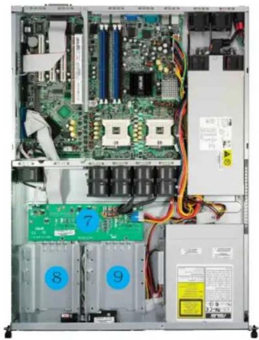
Interior view of a server rack with visible CPU socket, RAM slots, and drive bays (no readable text or symbols)natural_image
Front view of a server rack unit with visible ports and ventilation slots, showing no readable text or symbols.natural_image
Close-up of a hand adjusting a green circuit board with visible components and a magnified inset showing a component (no text or symbols)金三角方向标示 图形
natural_image
Close-up of a green printed circuit board with visible components like CPU, resistors, and capacitors (no text or symbols)2.2.2 安装 CPU 散热片
natural_image
Close-up of a hand placing a red electronic component onto a computer motherboard with visible circuit boards and components (no text or symbols)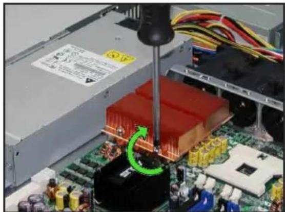
natural_image
Close-up of a computer motherboard with a green circular arrow indicating a machining process (no visible text or symbols)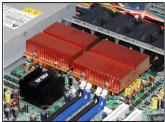
natural_image
Close-up of a computer motherboard with red and blue heatsink heat sinks (no visible text or symbols)2.3 系统内存
2.3.1 概述
2.3.2 内存设置
natural_image
Close-up of a green RAM module being inserted into a black housing, with magnified inset showing internal components (no text or symbols visible)2.4.4 去除内存条
natural_image
Hand inserting a USB into a server rack with visible circuit boards and connectors (no text or symbols)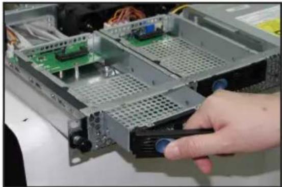
natural_image
Hand inserting a device into a server rack with visible circuit boards and connectors (no text or symbols)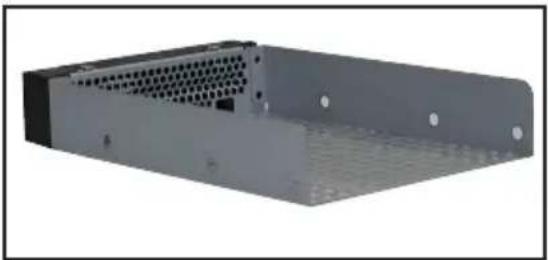
natural_image
3D rendering of a gray server rack unit with ventilation grilles and mounting holes (no text or symbols visible)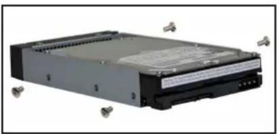
natural_image
Exterior view of a black internal computer drive with metallic connectors (no visible text or symbols)natural_image
Close-up of a hand inserting a drive into a server rack with an electronic circuit board (no visible text or symbols)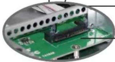
natural_image
Close-up of a green circuit board with electronic components and wiring (no visible text or symbols)背板上的 SATA 接口接孔

natural_image
Close-up of a hand inserting a CD into a server rack with visible drive bays and cable (no text or symbols)natural_image
Interior view of a computer motherboard with a green circuit board and screwdriver inserted (no visible text or symbols)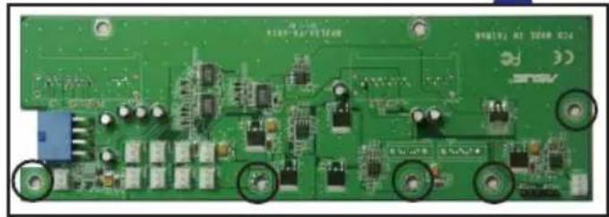
natural_image
Close-up of a green printed circuit board with visible components and mounting holes (no readable text or symbols)natural_image
Close-up of a metal frame structure with hexagonal lattice panels and a red screwdriver inserted (no visible text or symbols)固定沟槽
natural_image
Circular cropped image showing a blurred, indistinct object with no visible text or symbolsnatural_image
Exterior view of a hard disk drive housing (no visible text or labels)natural_image
Close-up of a hard disk drive with a green arrow pointing to its internal component (no visible text or symbols)natural_image
Close-up of a hard disk drive being inserted into a computer chassis, with a green arrow indicating the motion direction (no text or symbols visible)natural_image
Close-up of a hard disk drive being inserted into a green circuit board, with a screwdriver inserted (no visible text or symbols)natural_image
Interior view of a computer drive showing internal components including a hard disk, circuit board, and cable (no visible text or symbols)
natural_image
Close-up of a computer motherboard with visible circuit boards and components, no text or symbols present.将 SATA 排线的另一端连接至主板上
natural_image
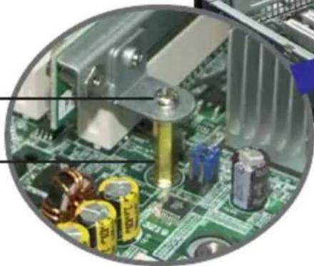
Close-up of a computer motherboard with a hand using a screwdriver to adjust components (no visible text or symbols)转接卡上的固定螺丝
固定铜柱
natural_image
Close-up of a computer motherboard with visible components including CPU socket, capacitors, and heat sink (no text or symbols)natural_image
Close-up of a computer motherboard with a hand inserting a slot into the CPU socket (no visible text or labels)natural_image
Close-up of a mechanical component with green circuit board and red screwdriver (no visible text or symbols)natural_image
3D rendering of a green circuit board with multiple connectors and components (no visible text or symbols)natural_image
Close-up of a green computer motherboard with visible slots and connectors (no text or symbols)natural_image
Close-up of hands installing a green circuit board into an open computer motherboard (no visible text or symbols)natural_image
Close-up of a computer motherboard showing CPU socket, cooling elements, and a green circuit board (no visible text or symbols)2.5.2 设置扩充卡
预先连接的系统排线
预先连接的系统排线
natural_image
Internal view of a server rack with visible CPU socket, motherboard, and power unit (no text or symbols)natural_image
Close-up of a hand using a screwdriver to adjust or install a computer drive into an open chassis (no visible text or symbols)natural_image
Close-up of a hand holding a black Audi CD card with 'ASIS' branding, no visible text or symbols on the card itself.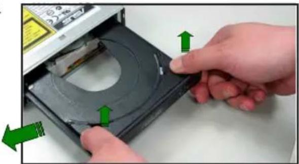
natural_image
Close-up of hands installing a CD into a disc, showing green directional arrows indicating assembly or repair (no text or symbols visible)- 去除连接在光驱后端的电源适配器及排线。
natural_image
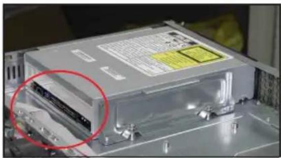
Close-up of a computer drive chassis with a highlighted cable component (no visible text or symbols)natural_image
Close-up of a hand using a screwdriver to adjust or install an electronic drive into a CD-ROM (no visible text or symbols)安装光驱
依照以下的步骤安装光驱:
natural_image
Close-up of hands holding a black USB flash drive (no visible text or symbols)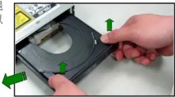
natural_image
Close-up of hands inserting a CD into an optical disc (no text or symbols visible)natural_image
Close-up of a computer drive with green arrows indicating motion, no visible text or symbols2.7.5 主板
去除主板
请依照以下的步骤来去除主板:
natural_image
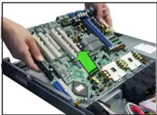
Close-up of a hand using a screwdriver to adjust or repair an electronic circuit board (no visible text or symbols)- 如图所示,小心地将主板自机箱中取出来。
natural_image
Close-up of hands installing a computer motherboard with a green arrow pointing to a specific circuit board (no text or symbols visible)安装主板
请依照以下的步骤来安装主板:
- 握住主板的二侧,小心地装入机箱底部。

natural_image
Close-up of hands installing a computer motherboard with a green arrow pointing to a specific component (no text or symbols visible)natural_image
Interior view of a computer motherboard showing CPU socket, RAM slots, and drive bays (no visible text or labels)natural_image
Close-up of a hand using a screwdriver to adjust or install a computer motherboard (no visible text or symbols)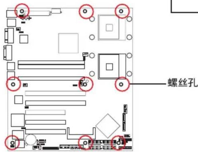
natural_image
Close-up of a green printed circuit board with various electronic components and a highlighted component (no visible text or symbols)natural_image
Interior view of a server rack with internal components and wiring, showing CPU socket, drive bays, and power bank (no readable text or symbols)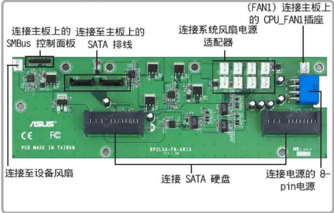
natural_image
Interior view of a server rack with visible CPU socket, RAM slots, and motherboard (no readable text or symbols)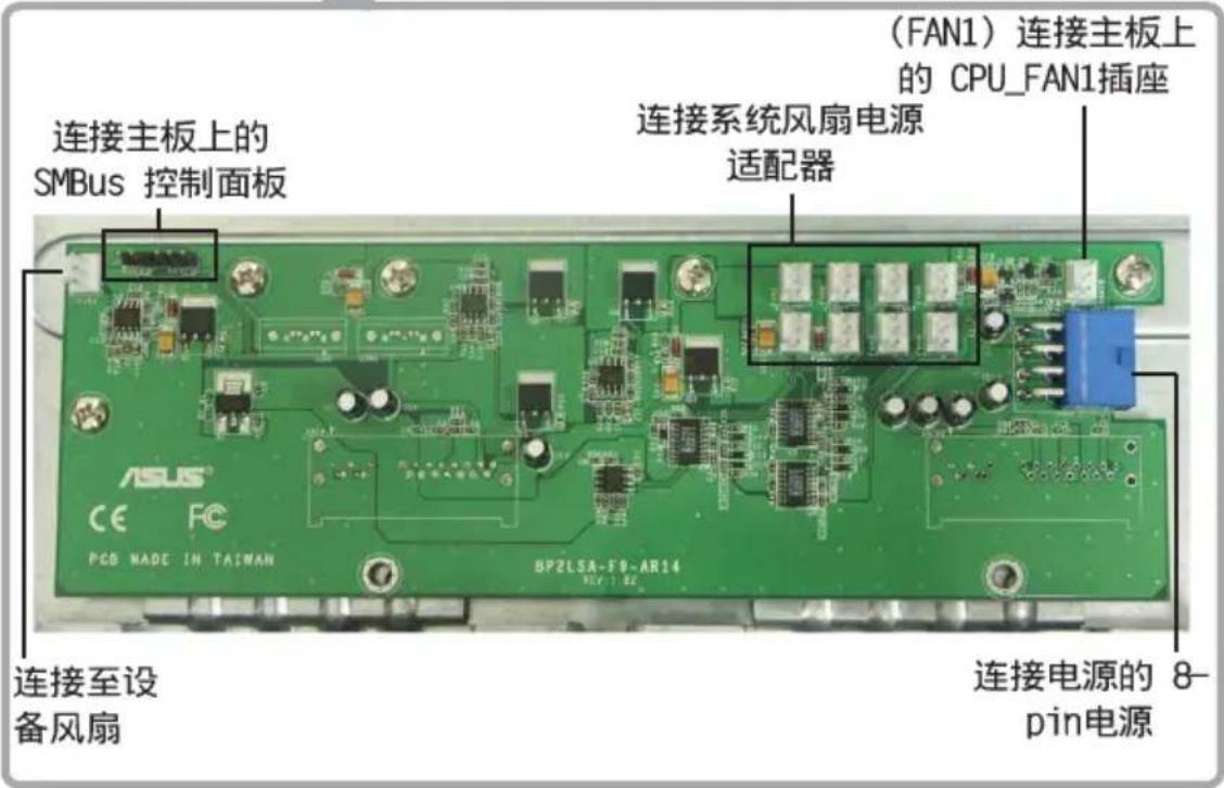
natural_image
Front view of a server rack unit with multiple ports and ventilation grilles (no visible text or labels)3.1 滑轨套件
natural_image
Close-up of a white metal bracket with three metallic pins, mounted on a black metal frame (no text or symbols visible)natural_image
Diagram showing two server racks connected by a green double-headed arrow, with a meshed panel inside (no text or symbols)3.4 安装服务器至机架上
请依照以下步骤将服务器安装至机架上:
natural_image
Close-up of hands installing a server rack with a green arrow pointing to a component, no visible text or symbolsnatural_image
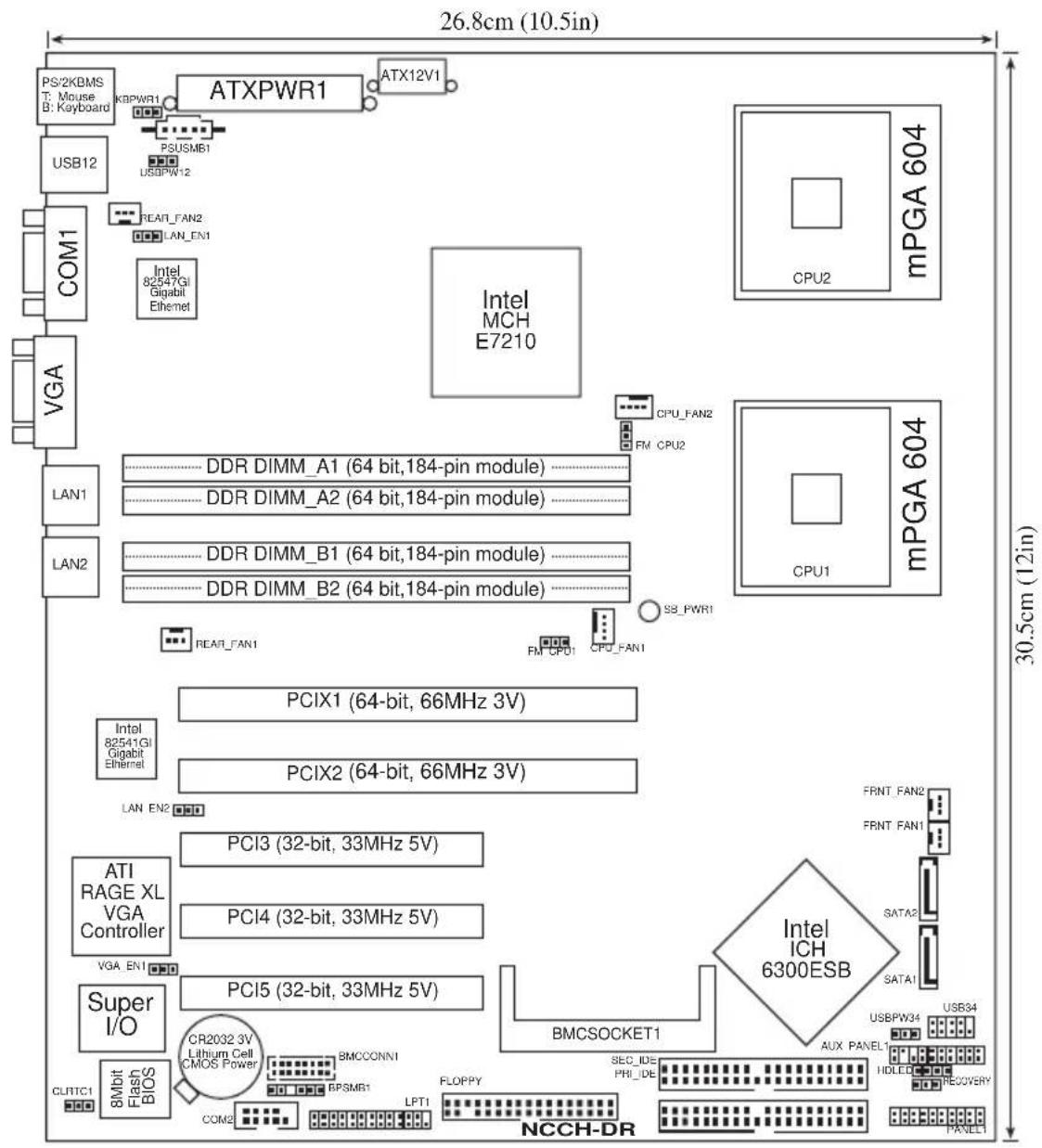
Front view of a server rack unit with ventilation grilles and ports (no visible text or labels)4.1 主板结构图

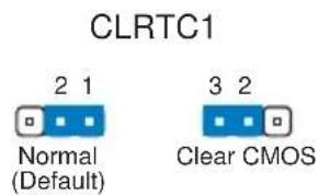
NCCH-DR Clear RTC RAM
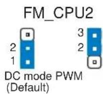
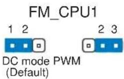
2. CPU 风扇电源适配器设置 (3-pin FM\_CPU1, FM\_CPU2)
NCCH-DR FM_CPU setting
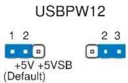
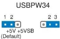
3. USB 设备唤醒功能设置 (3-pin USBPW12, USBPW34)
NCCH-DR USB device wake-up

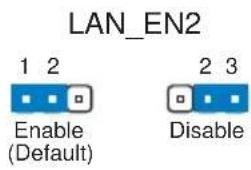
NCCH-DR LAN_EN2 setting
natural_image
Pure electrical circuit lines without any symbolsRECOVERY
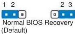
NCCH-DR BIOS recovery setting
4.3 元件与外围设备的连接
FLOPPY
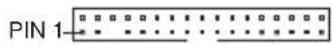
NOTE: Orient the red markings on the floppy ribbon cable to PIN 1.
NCCH-DR Floppy disk drive connector
2. IDE 设备连接插座 (40-1 pin PRI\_IDE, SEC\_IDE)
natural_image
Floor plan layout diagram with room labels and directional arrow (no text or symbols)NCCH-DR IDE connectors
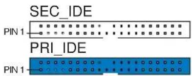
NOTE: Orient the red markings (usually zigzag) on the IDE ribbon cable to PIN 1.
3.Serial ATA 设备连接插座 (7-pin SATA1, SATA2)
natural_image
Pure technical diagram of a computer motherboard layout without any text, numbers, or symbolsNCCH-DR SATA connectors
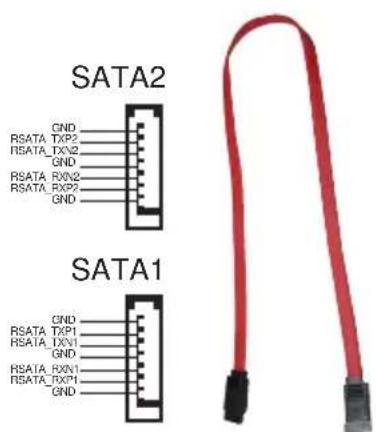

Serial ATA 重点提示:
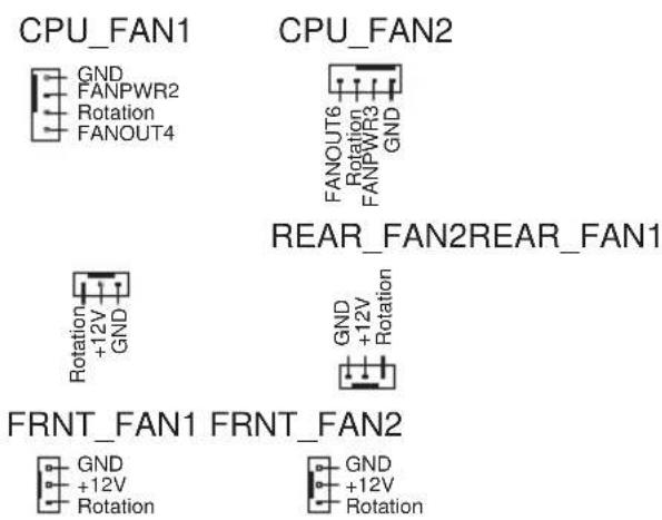
NCCH-DR Fan connectors
6.USB 2.0 接针 (10-1pin USB34)
natural_image
Floor plan layout with room layouts and furniture placement (no text or labels)NCCH-DR
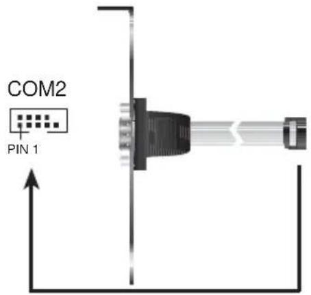
Serial port2 (COM2) connector
8.SSI 规格主板电源插座(24-pin ATXPWR1,8-pin ATX12V1)
NCCH-DR SMBus connector
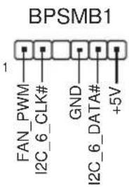
NCCH-DR Power supply SMBus connector
natural_image
Pure architectural floor plan lines without any text, numbers, or symbols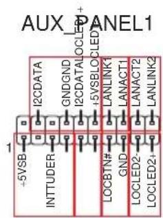
NCCH-DR Auxiliary panel connector
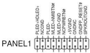
NCCH-DR System panel connector
natural_image
Front view of a server rack unit with ventilation fans and ports (no visible text or labels)5.1 管理、升级您的 BIOS 程序

Award BootBlock BIOS v.1.0
Copyright (C) 2000, Award Software, Inc.
BIOS ROM checksum error
Detecting IDE ATAPI device...
Found CD-ROM, try to Boot from it...Pass
1. FD 1.44MB System Type-(00)
Loading FreeDOS FAT KERNEL GO!
Press any key to boot from CDROM...
The BIOS was corrupted! Do you want to recover? (y/n)
- 按下
键后,就会出现如下的画面。
Would you like to FLASH bios now? (y/n)
Yes or No _
AwardBIOS Flash Utility for ASUS V1.06
(C) Phoenix Technologies Ltd. All Rights Reserved

For Canterwood - NCCH-DRC-00 DATE: 07/14/2004
Flash Type - SST 49LF004A /3.3V

File Name to Program :
| Main Advanced Power Boot Exit | |
| System Time 11: 10:30 System Date Wed, Jui 21 2004 Legacy Diskette A: [1.44M, 3.5 in.] Floppy 3 Mode Support [Disabled] Primary IDE Master [None] Primary IDE Slave [None] Secondary IDE Master [None] Secondary IDE Slave [None] Third IDE Master [None] Fourth IDE Master [None] Base Mamory 640K Extended Memory 260096K Total Memory 261120K | Select Menu |
| Item Specific Help Change the internal clock. | |
| F1:Help ↑↓:Select Item -/+ : Change Value F5:Setup Defaults ESC:Exit ++:Select Menu Enter: Select SubMenu F10:Save and Exit | |
Time [hh:mm:ss]
Legacy Diskette A [1.44M, 3.5 in.]
本项目存储了软驱的相关信息,设置值有:[None] [360K, 5.25 in.] [1.2M, 5.25 in.] [720K, 3.5 in.] [1.44M 3.5 in.] [2.88M, 3.5 in.]。
Floppy 3 Mode Support [Disabled]
Base/Extended/Total Memory [xxxK]
| Select MenuPrimary Master | |
| Primary IDE Master [Auto] Access Mode [Auto] Capacity 0 MB Cylinder 0 Head 0 Precomp 0 Landing Zone 0 Sector 0 PIO Mode [Auto] UDMA Mode [Auto] Transfer Mode None S.M.A.R.T Status None | Item Specific Help ▶ Selects the type of fixed disk connected to the system. [Manual] lets you select the number of cylinders, heads, etc. Note: PRECOMP-65535 means NONE. |
| F1:Help ↑↓:Select Item -/+ : Change Value F5:Setup Defaults ESC:Exit ++:Select Menu Enter: Select SubMenu F10:Save and Exit | |
Primary IDE [Auto]
Manual detecting an IDE drive

5.3.2 Primary IDE Slave
5.3.3 Secondary IDE Master
5.3.4 Secondary IDE Slave
| Advanced BIOS Features | Select Menu |
| Console Redirection [Disabled] Baud Rate 19200 Agent Address [Auto] Agent after boot [Disabled] | Item Specific Help ▶ Enabled - Attempt to redirect console via COM port. Disabled - Attempt to redirect console when keyboard is absent. |
| F1:Help ↑↓:Select Item -/+ : Change Value F5:Setup Defaults ESC:Exit ++:Select Menu Enter: Select SubMenu F10:Save and Exit | |
Console Redirection [Disabled]
Agent Address [Auto]
Agent after boot [Disabled]
CPU L1 & L2 Cache [Enabled]
| Memory Configuration | Select Menu |
| DRAM Frequency [Auto] Memory Timing Selectable [By SPD] Cache Latency Time 2 Active to Precharge Delay 6 DRAM RAS# to CAS# Delay 3 DRAM RAS# Precharge 3 DRAM Data Integrity Mode [ECC] | Item Specific Help ▶ Set DRAM Frequency. |
| F1:Help ↑↓:Select Item -/+: Change Value F5:Setup Defaults ESC:Exit ++:Select Menu Enter: Select SubMenu F10:Save and Exit | |
DRAM Frequency [Auto]
本选项设置 DRAM 操作频率。设置值有:[DDR266] [DDR333] [DDR400] [Auto]
Memory Timing Selectable [By SPD]
CAS Latency Time [2]
Active to Precharge Delay [6]
DRAM RAS# to CAS# Delay [3]
DRAM Data Integrity Mode [ECC]
| Chipset | Select Menu |
| System BIOS Cacheable [Enabled] Video BIOS Cacheable [Disabled] Init Display First [PCI VGA Card] Auto Detect PCI Clk [Enabled] | Item Specific Help ▶ Press <Enter> to enabled or disable BIOS cacheable. |
System BIOS Cacheable [Enabled]
Init Display First [PCI VGA Card]
H/W Jumper of CSA LAN [Enabled]
H/W Jumper of ONB LAN [Enabled]
| Phoenix - Award BIOS CMOS Setup Utility Advanced | |
| SuperIO Device | Select Menu |
| Serial Port1 Address [3F8/IRQ4] Serial Port2 Address [2F8/IRQ3] Onboard Parallel Port [378/IRQ7] Parallel Port Mode [SPP] EPP Mode Select EPP1.7 ECP Mode Use DMA 3 | Item Specific Help ▶▶▶ Set Base I/O address for serial port 1. |
| F1:Help ↑↓:Select Item -/-: Change Value F5:Setup Defaults ESC:Exit ←:Select Menu Enter: Select SubMenu F10:Save and Exit | |
Serial Port 1 Address [3F8/IRQ4]
Serial Port 2 Address [2F8/IRQ3]
Onboard Parallel Port [378/IRQ7]
Parallel Port Mode [SPP]
本项目让您选择并口的模式。设置值有:[SPP] [EPP] [ECP] [ECP+EPP] [Norma1]
EPP Mode Select [EPP1.7]
| SATA Configuration | Select Menu |
| *** On-Chip Serial ATA Setting *** On-Chip Serial ATA [Auto] SATA Mode IDE Serial ATA Port0 Mode SATA0 master Serial ATA Port1 Mode SATA1 master | Item Specific Help >>> [Disabled]: Disable SATA Controller. [Auto]: Auto-arrange the BIOS. [Combined Mode]: PATA and SATA are combined. Max. of 2 IDE drives on each channel. [Enhanced Mode]: Enable both SATA and PATA. Max. of 6 IDE drives are supported. [SATA Only]: SATA is opeating in legacy mode. |
| F1:Help ↑↓:Select Item -/+ : Change Value F5: Setup Defaults ESC: Exit ++:Select Menu Enter: Select SubMenu F10: Save and Exit | |
\*\*芯片内置串行 ATA 设置

On-chip Serial ATA [Auto]
Serial ATA Port0 Mode [SATA0 master] Serial ATA Port1 Mode [SATA1 master]
本项目让您设置串行 ATA Port0 及串行 ATA Port1 模式,本项目将因 [On-Chip Serial ATA] 项目的设置值而改变。设置值有:[Primary Master] [Primary Slave] [Secondary Master] [Secondary Slave] [SATAO master] [SATA1 master]
5.4.6 PnP/PCI 设置
| Phoenix Award BIOS CMOS Setup Utility Advanced | |
| PCIPnP | Select Menu |
| Resources Controlled By [Auto] IRQ Resources PCI/VGA Pallete Snoop [Disabled] INT Pin 1 Assignment [Auto] INT Pin 2 Assignment [Auto] INT Pin 3 Assignment [Auto] INT Pin 4 Assignment [Auto] INT Pin 5 Assignment [Auto] INT Pin 6 Assignment [Auto] INT Pin 7 Assignment [Auto] INT Pin 8 Assignment [Auto] | Item Specific Help ▶ Default is Disabled. Select Enabled to reset Extended System Configuration Data (ESCD) upon exiting Setup, if you installed a new add-on card and the system cannot boot due to a serious conflict in system configuration. |
| F1:Help ↑↓:Select Item -/+ : Change Value F5:Setup Defaults ESC:Exit ++:Select Menu Enter: Select SubMenu F10:Save and Exit | |
Resources Controlled By [Auto]
INT Pin 1\~8 Assignment [Auto]
本项目可让您选择适当的中断地址给特定设备,避免冲突发生。设置值有:[Auto] [3] [4] [5] [7] [9] [10] [11] [12] [14] [15]
IRQ Resources

| PCIPnP | Select Menu |
| Resources Controlled By [Manual] ►IRQ Resources PCI/VGA Pallete Snoop [Disabled] INT Pin 1 Assignment [Auto] INT Pin 2 Assignment [Auto] INT Pin 3 Assignment [Auto] INT Pin 4 Assignment [Auto] | Item Specific Help ▶ When resources are controlled manually, assign each system interrupt a type depending on the type of device using the interrupt. |
| IRQ Resources | Select Menu | |
| IRQ-3 assigned to [PCI Device] | Item Specific Help >> | |
| IRQ-4 assigned to [PCI Device] | Legacy ISA for devices compliant with the original PC AT bus specification, PCI/ISA PnP for devices compliant with the Plug and Play standard whether designed for PCI or ISa bus architecture. | |
| IRQ-5 assigned to [PCI Device] | ||
| IRQ-7 assigned to [PCI Device] | ||
| IRQ-9 assigned to [PCI Device] | ||
| IRQ-10 assigned to [PCI Device] | ||
| IRQ-11 assigned to [PCI Device] | ||
| IRQ-12 assigned to [PCI Device] | ||
| IRQ-14 assigned to [PCI Device] | ||
| IRQ-15 assigned to [PCI Device] | ||
| F1:Help ↑↓:Select Item -/+ : Change Value F5:Setup Defaults ESC:Exit ←:Select Menu Enter: Select SubMenu F10:Save and Exit | ||
IRQ-xx assigned to [PCI device]
USB 2.0 Support [Enabled]
USB Legacy Mode Support [Enabled]
| Main Advanced Power Boot Exit | |
| ACPI APIC Support [Enabled] ▶ APM Configuration ▶ Hardware Configuration | Select Menu |
| Item Specific Help ▶ Enable/Disable ACPI support for Operating System. | |
| F1:Help ↑↓:Select Item -/+ : Change Value F5:Setup Defaults ESC:Exit ++:Select Menu Enter: Select SubMenu F10:Save and Exit | |
ACPI APIC Support [Enabled]
| Phoenix - Award BIOS CMOS Setup Utility Power | |
| APM Configuration | Select Menu |
| Power Management [User Define] HDD Power Down [Disabled] Suspend Mode [Disabled] Suspend Type [Stop Grant] Restore on AC Power Loss [Power Off] Video Off Method [DPMS] Video Off In Suspend [Yes] MODEM Use IRQ [3] Soft-Off by PWR-BTN [Instant-Off] Power On By PCI Devices [Enabled] Power On By External Modem [Disabled] POWER ON Function [Button Only] KB Power On Password Enter Hot Key Power ON Ctrl-F1 Resume By Alarm [Disabled] Date (of Month) Alarm 0 Time (hh:mm:ss) Alarm 0: 0: 0 | Item Specific Help ▶ This field allows you to set the automatic power saving features. |
| F1:Help ↑↓:Select Item -/*: Change Value F5:Setup Defaults ESC:Exit ←:Select Menu Enter: Select SubMenu F10:Save and Exit | |
Power Management [User Define]
本项目让您设置自动能源节电功能。设置值有:[User Define] [Min. Saving] [Max. Saving]
HDD Power Down [Disabled]
Suspend Type [Stop Grant]
Restore on AC Power Loss [Power Off]
若设置为 [Power Off],则当系统在电源中断之后电源将维持关闭状态。若设置为 [Power On],当系统在电源中断之后重新开启。若设置为 [Last State],会将系统设置恢复到电源未中断之前的状态。设置值有:[Power Off] [Power On] [Last State]
Video Off Method [DPMS]
Soft-Off by PWR-BTTN [Instant-Off]
Power On by PCI Card [Enabled]
Power On by External Modem [Disabled]
Hot Key Power On Password [Ctrl-F1]
Resume by Alarm [Disabled]
Date (of Month) Alarm [0]
| Smart Q-Fan Configuration | Select Menu |
| Smart Fan Control [Disabled] System Target Temperature 50 CPU1 Target Temperature 55 | Item Specific Help ▶▶▶ Press Enter to enable or disable the Smart Fan. |
Smart Fan Control [Disabled]
System Target Temperature [50]
CPU1 Target Temperature [55]
| Phoenix - Award BIOS CMOS Setup Utility Main Advanced Power Boot Exit | |
| Boot Device Priority 1st Boot Device [Removable] 2nd Boot Device [CDROM] 3rd Boot Device [Hard Disk] | Select Menu Item Specific Help ▶ Select your Boot Device Priority. |
| F1:Help ↑↓:Select Item -/+: Change Value F5:Setup Defaults ESC:Exit ++:Select Menu Enter: Select SubMenu F10:Save and Exit | |
1st Boot Device [Removable]
1nd Boot Device [CDROM]
3rd Boot Device [Hard Disk]
| Phoenix - Award BIOS CMOS Setup Utility | |
| Boot | |
| Hard Disk Boot Priority | Select Menu |
| 1. 1st Master: XXXXXXXX 2. Bootable Add-in Cards | Item Specific Help ▶ Use <up> or <down> arrow to select a device, then press <+> to move it up, or <-> to move it down the list. Press <ESC> to exit this menu. |
| F1:Help ↑↓:Select Item -/+ : Change Value F5:Setup Defaults ESC:Exit ++:Select Menu Enter: Select SubMenu F10:Save and Exit | |
5.6.3 Removable Device Priority
| Removable Device Priority | Select Menu |
| 1. Floppy Disks | Item Specific Help ▶ Use <up> or <down> arrow to select a device, then press <+> to move it up, or <-> to move it down the list. Press <ESC> to exit this menu. |
| F1:Help ↑↓:Select Item -/+ : Change Value F5:Setup Defaults ESC:Exit ←:Select Menu Enter: Select SubMenu F10:Save and Exit | |
5.6.4 CD-ROM Boot Priority
| Phoenix - Award BIOS CMOS Setup Utility Boot | |
| Removable Device Priority | Select Menu |
| 1. 1st Slave: ASUS CD-S520 /A | Item Specific Help ▶ Use <up> or <down> arrow to select a device, then press <+> to move it up, or <-> to move it down the list. Press <ESC> to exit this menu. |
| F1:Help ↑↓:Select Item -/+ : Change Value F5:Setup Defaults ESC:Exit ++:Select Menu Enter: Select SubMenu F10:Save and Exit | |
5.6.5 啟動選項設置 Configuration
| Boot Settings Configuration | Select Menu |
| Boot Other Device [Enabled] Quick Power On Self Test [Enabled] Halt On [All Errors] Case Open Warning [Enabled] Boot Up Floppy Seek [Enabled] Boot Up NumLock Status [On] Typematic Rate Setting [Disabled] Typematic Rate (Chars/Sec) 6 Typematic Delay (Msec) 250 Full Screen Logo Show [Enabled] | Item Specific Help ▶ Select your Boot Device Priority. |
| F1:Help ↑↓:Select Item -/+ : Change Value F5:Setup Defaults ESC:Exit ++:Select Menu Enter: Select SubMenu F10:Save and Exit | |
Boot Other Device [Enabled]
Quick Power On Self Test [Enabled]
Typematic Rate(Chars/Sec) [6]
Typematic Delay(Msec) [250]
Full Screen Logo Show [Enable]
| Security | Select Menu |
| Supervisor Password Clear User Password Clear Password Check [Setup] | Item Specific Help ▶ Supervisor password control full access. |
| F1:Help ↑↓:Select Item -/+ : Change Value F5: Setup Defaults ESC Exit ++: Select Menu Enter: Select SubMenu F10: Save and Exit | |
Supervisor Password [Clear]
User Password [Clear]
Password Check [Setup]
| Phoenix - Award BIOS CMOS Setup Utility | |
| Main Advanced Power Boot Exit | |
| Exit & Save Changes Exit & Discard Changes Load Setup Defaults Discard Changes | Select Menu |
| Item Specific Help ▶ This option saves data to CMOS before exiting Setup. | |
| F1:Help ↑↓:Select Item -/→: Change Value F5:Setup Defaults ESC:Exit ←:Select Menu Enter: Select SubMenu F10:Save and Exit | |
Exit & Save Setup
Exit & Discard Changes
natural_image
Front view of a server rack unit with multiple ports and ventilation grilles (no visible text or labels)6.1 RAID 功能设置
Adaptec Embedded SATA HostRAID BIOS V2.2-1 1237
(c) 1998-2004 Adaptec, Inc. All Rights Reserved.
*** Press <Ctrl><A> for Adaptec RAID Configuration Utility! ***
Controller #00: HostRAID-ICHS at PCI Bus:00, Dev:1F, Func:02
Loading Configuration...Done.
Port#00 ST380023AS 3.01 74.53 GB Healthy
Port#01 ST380023AS 3.01 74.53 GB Healthy
SATA JBOD- PORT-0 ST380023AS 74.53 GB
SATA JBOD- PORT-1 ST380023AS 74.53 GB
2 JBOD Device(s) Found.
![Array Properties Array Type : RAID 1(Mirror) Array Label : 6300ESB Array Size : 74.500 GB Stripe Size : N/A Create RAID via : [Done] Next Field, Previous Field Accept Value. Cancel Dialog Box, Help](/content/2026/06/1167391/images/7b0f71793360bfdffbfda550ac57d3d683e9df1fde61abb7f17cf87ee81a39e5.jpg)

删除 RAID 1 设置
重新创建 RAID 硬盘
附录 A
Migrate 功能
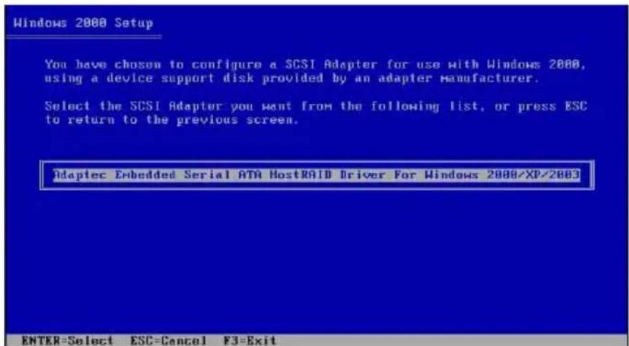
- 选择【Adaptec Embedded Serial ATA HostRAID Driver for Windows 2000/XP/2003】,然后按下
确认。
6.3 安装网络驱动程序
本章节将介绍如何安装网络驱动程序。

此处的「XXX」代表为各位所安装的
的型号。

此处的「XXX」代表为各位所安装的
的型号。
RedHat Linux 操作系统
- 给用户的说明
- 高级菜单 (Advanced Menu) 5-20
- 产品包装内容
- 安装 CPU 散热片
- 系统内存
- 概述
- 内存设置
- 去除内存条
- 设置扩充卡
- 预先连接的系统排线
- 安装光驱
- 主板
- 去除主板
- 安装主板
- 滑轨套件
- 安装服务器至机架上
- 主板结构图
- CPU 风扇电源适配器设置 (3-pin FM\_CPU1, FM\_CPU2)
- USB 设备唤醒功能设置 (3-pin USBPW12, USBPW34)
- 元件与外围设备的连接
- IDE 设备连接插座 (40-1 pin PRI\_IDE, SEC\_IDE)
- 3.Serial ATA 设备连接插座 (7-pin SATA1, SATA2)
- 6.USB 2.0 接针 (10-1pin USB34)
- 8.SSI 规格主板电源插座(24-pin ATXPWR1,8-pin ATX12V1)
- 管理、升级您的 BIOS 程序
- Time [hh:mm:ss]
- Legacy Diskette A [1.44M, 3.5 in.]
- Floppy 3 Mode Support [Disabled]
- Base/Extended/Total Memory [xxxK]
- Primary IDE [Auto]
- Manual detecting an IDE drive
- Primary IDE Slave
- Secondary IDE Master
- Secondary IDE Slave
- Console Redirection [Disabled]
- Agent Address [Auto]
- Agent after boot [Disabled]
- CPU L1 & L2 Cache [Enabled]
- \*\*芯片内置串行 ATA 设置
- On-chip Serial ATA [Auto]
- Serial ATA Port0 Mode [SATA0 master] Serial ATA Port1 Mode [SATA1 master]
- PnP/PCI 设置
- Resources Controlled By [Auto]
- INT Pin 1\~8 Assignment [Auto]
- IRQ Resources
- IRQ-xx assigned to [PCI device]
- USB 2.0 Support [Enabled]
- USB Legacy Mode Support [Enabled]
- ACPI APIC Support [Enabled]
- Video Off Method [DPMS]
- Soft-Off by PWR-BTTN [Instant-Off]
- Power On by PCI Card [Enabled]
- Power On by External Modem [Disabled]
- Hot Key Power On Password [Ctrl-F1]
- Resume by Alarm [Disabled]
- Date (of Month) Alarm [0]
- Smart Fan Control [Disabled]
- System Target Temperature [50]
- CPU1 Target Temperature [55]
- Removable Device Priority
- CD-ROM Boot Priority
- 啟動選項設置 Configuration
- Boot Other Device [Enabled]
- Quick Power On Self Test [Enabled]
- Typematic Rate(Chars/Sec) [6]
- Typematic Delay(Msec) [250]
- Full Screen Logo Show [Enable]
- Supervisor Password [Clear]
- User Password [Clear]
- Password Check [Setup]
- Exit & Save Setup
- Exit & Discard Changes
- RAID 功能设置
- 删除 RAID 1 设置
- 重新创建 RAID 硬盘
- 附录 A
- Migrate 功能
- 安装网络驱动程序
- RedHat Linux 操作系统
Brand : ASUS
Model : AP1600R-E2
Category : Server