AP1720-E2 - Server ASUS - Free user manual and instructions
Find the device manual for free AP1720-E2 ASUS in PDF.

User questions about AP1720-E2 ASUS
0 question about this device. Answer the ones you know or ask your own.
Ask a new question about this device
Download the instructions for your Server in PDF format for free! Find your manual AP1720-E2 - ASUS and take your electronic device back in hand. On this page are published all the documents necessary for the use of your device. AP1720-E2 by ASUS.
USER MANUAL AP1720-E2 ASUS
natural_image
Illustration of a desktop computer tower with black and silver panels and ventilation slots (no text or symbols)C1855
1.00 版
2004 年 11 月发行
5.3.1 Primary IDE Master 次菜单 5-12
5.3.2 Primary IDE Slave 5-15
5.3.3 Secondary IDE Master 5-15
5.3.4 Secondary IDE Slave 5-15
5.3.5 Third IDE Master 5-16
5.3.6 Fourth IDE Master 5-16
5.4 高级菜单 (Advanced Menu) 5-17
地址:Harkort Str. 25, D-40880 Ratingen, BRD, Germany
电话:+49-2102-95990
传真:+49-2102-959911
natural_image
Illustration of a desktop server tower with multiple drive bays and indicator lights (no text or symbols)1.1 产品包装内容
natural_image
Exterior view of a server tower with three vertical drive bays (no text or symbols visible)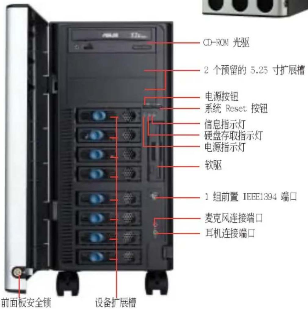
1.4 后端面板
natural_image
Close-up of hands installing a server rack with a green upward arrow indicating a component (no text or symbols visible)natural_image
Person installing a server rack with a highlighted green arrow pointing to the next rack (no text or symbols visible)检视内部结构
2.2 主板信息

natural_image
Close-up of a computer motherboard with visible CPU socket and circuit board (no text or symbols)natural_image
Close-up of a hand pressing down on a computer motherboard with a highlighted circular component (no visible text or symbols)金三角符号
natural_image
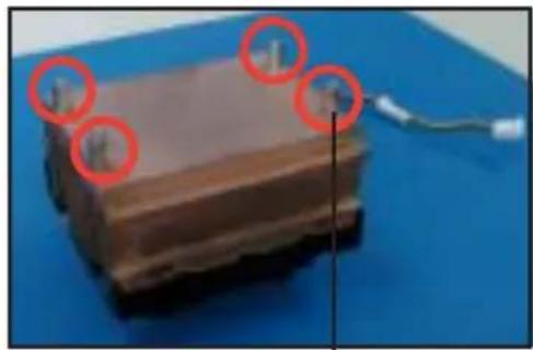
Close-up of a green printed circuit board with visible components and gold-colored capacitors (no text or symbols)2.3.3 安装 CPU 散热片与风扇
natural_image
Close-up of a small electronic device with a black fan and coiled cable, placed on a blue surface (no visible text or symbols)处理器散热器(底视图)
natural_image
Close-up of a layered material sample with red circles highlighting features, placed on a blue surface (no text or symbols visible)散热器底座固定铜柱

当您进行安装处理器专用散热器前:
natural_image
Close-up of hands installing a CPU socket into a motherboard (no visible text or symbols)
natural_image
Close-up of hands working on a computer motherboard with CPU socket and circuit board (no visible text or symbols)natural_image
Close-up of a computer motherboard with CPU socket and monitor, no visible text or symbols
natural_image
Close-up of a computer keyboard with visible network cables and a black pointer (no text or symbols)2.4.2 内存设置
natural_image
Close-up of a green RAM module with circular annotations highlighting the components (no text or symbols present)2.5 前面板的组装
2.5.1 去除前面板组件

natural_image
Close-up of hands installing or adjusting a server rack with a green arrow pointing to a component (no visible text or symbols)natural_image
Interior view of a computer tower case showing internal circuit boards and drive bays (no visible text or labels)
natural_image
Close-up of a computer motherboard showing a CD drive with multiple ports and indicator lights (no readable text or symbols)natural_image
Interior view of a computer rack with labeled ports and a highlighted green arrow pointing to a component (no readable text or symbols)插槽固定锁片 固定扣
natural_image
Close-up of hands installing or adjusting a CD-ROM drive into a computer tower (no visible text or symbols)
natural_image
Close-up of a computer washing machine with visible wiring and socket (no text or symbols)IDE 排线 插入电源适配器
natural_image
Internal view of a computer tower case with visible connectors and wiring (no text or symbols)natural_image
Close-up of a computer drive bay with multiple ports and a highlighted green arrow pointing to a specific component (no text or symbols visible)natural_image
Two views of a server rack with an open door, showing internal components and a close-up of the interior (no text or symbols visible)natural_image
Close-up of a hand inserting a component into a device, with a green arrow indicating the next component (no visible text or symbols)natural_image
Close-up of a mechanical device with green directional arrows indicating movement or force (no text or symbols visible)natural_image
Close-up of a hand inserting a component into a device, with a green arrow indicating direction (no text or symbols visible)natural_image
Close-up of a finger pointing to a black electronic device with ports and a green arrow indicating a specific component (no text or symbols visible)2.7.2 安装 IDE 硬盘
natural_image
Close-up of hands installing or adjusting a computer drive into a rack (no visible text or symbols)natural_image
Interior view of an electronic equipment cabinet with exposed wiring and control panels (no visible text or symbols)natural_image
Close-up of a computer tower drive showing a yellow tool interacting with a white object (no visible text or symbols)安装 SATA 硬盘到硬盘槽中
natural_image
Close-up of a hand using a tool to adjust or install a CD drive into an open computer tower (no visible text or symbols)natural_image
Close-up of hands connecting cables to a computer tower, no visible text or symbolsnatural_image
Hand inserting a USB into a computer tower case (no visible text or symbols)natural_image
Hand inserting a CD into a computer drive (no visible text or symbols)natural_image
Interior view of a computer drive bay with visible wiring and components (no text or symbols)安装硬盘槽饰板
natural_image
Close-up of a black electronic device with a display screen and control buttons (no visible text or symbols)2.8 扩充插槽
natural_image
Close-up of a computer motherboard with visible circuit board and soldering wires (no text or symbols)natural_image
Close-up of a computer motherboard with visible circuit board and CPU socket (no text or symbols)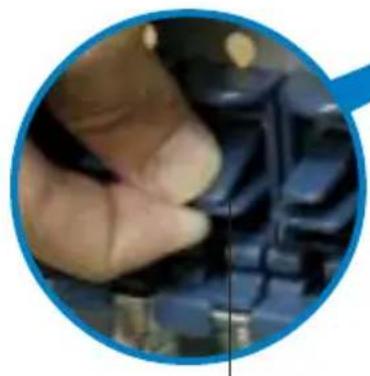
natural_image
Close-up of a hand holding a small electronic component, no visible text or symbols固定扣片
2.8.2 安装加长尺寸的扩充卡
natural_image
Close-up of hands installing a green circuit board on a computer motherboard (no visible text or symbols)natural_image
Close-up of hands holding a green circuit board inside a computer motherboard (no visible text or symbols)natural_image
Close-up of a computer motherboard with visible CPU socket, RAM slots, and drive bays (no text or symbols)natural_image
Close-up of a computer motherboard with a green arrow pointing to a green component (no visible text or symbols)2.9 连接排线

natural_image
Close-up of a green printed circuit board with visible traces and components (no text or symbols)natural_image
Close-up of a computer motherboard with CPU socket, RAM slots, and visible circuitry (no text or symbols)SATA RAID 控制芯片
| 背板编号 | 连接至主板的编号 | 控制芯片 |
| CON2 | SATA_RAID1 | Promise PDC20319 |
| CON4 | SATA_RAID2 | Promise PDC20319 |
| CON6 | SATA_RAID3 | Promise PDC20319 |
| CON8 | SATA_RAID4 | Promise PDC20319 |
natural_image
Close-up of a green printed circuit board with visible components and a red circle highlighting a small electronic component (no text or symbols)natural_image
Close-up of a green printed circuit board with a magnified inset showing internal components (no readable text or symbols)natural_image
Close-up of a green printed circuit board with a magnified inset showing internal components (no readable text or symbols)| 階梯設置 | |
| JPB組背板( )J1 設3 2-4 短路, 短路) | |
| 設備 | SCSI 硬盤槽 |
| 硬盤槽 1 ID0 | |
| 硬盤槽 2 ID1 | |
| 硬盤槽 3 ID2 | |
| 硬盤槽 4 ID3 | |
| GEM 318 SAF-TE | ID15 (SCSI Channel-0) |
| 階梯設置 | |
| JPB2背板( )J1 設4-6 短路, 短路) | |
| 設備 | SCSI 硬盤槽 |
| 硬盤槽5 ID0 | |
| 硬盤槽6 ID1 | |
| 硬盤槽7 ID2 | |
| 硬盤槽8 ID3 | |
| GEM 318 SAF-TE | ID15 (SCSI Channel-1) |

natural_image
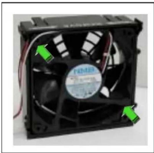
Close-up of a black CPU fan with visible wiring and a label, showing no readable text or symbols.请依照以下的步骤重新安装系统风扇:
- 首先,装入一个新的风扇至系统风扇盒内。
natural_image
Close-up of a black CPU fan with visible internal blades and green arrows indicating ports (no text or symbols on the fan itself)natural_image
Front view of a computer rack with multiple ports and a grid-patterned panel (no visible text or symbols)natural_image
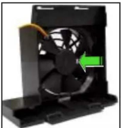
Close-up of a computer motherboard with visible CPU socket, RAM slots, and wiring (no readable text or symbols)2.10.2 硬盘风扇
请依照以下的步骤来去除硬盘风扇:
natural_image
Close-up of a hand pressing a blue component with a green circular arrow, next to a rack-mounted computer drive (no visible text or symbols)natural_image
Close-up of a hand inserting a CD into a rack-mounted computer drive, showing black and red slots with a green arrow indicating the direction (no text or symbols visible)
natural_image
Close-up of a computer CPU fan with red circles highlighting the blades (no text or symbols visible)natural_image
Close-up of a hand holding a black CPU fan with green directional arrows indicating rotation or adjustment (no text or symbols visible)natural_image
Close-up of hands holding a black CPU fan with a green upward arrow indicating rotation (no text or symbols visible)请依照以下的步骤重新安装硬盘风扇:
- 放入一个新的硬盘风扇于风扇盒内。
natural_image
Close-up of a black CPU fan with a green arrow indicating a specific component (no text or symbols visible)natural_image
Close-up of a hand inserting a blue drive into a rack-mounted server unit (no visible text or symbols)natural_image
Close-up of a hand pressing a green circular button on a blue electronic device panel (no visible text or symbols)2.10.3 SATA/SCSI 背板
natural_image
Interior view of a computer tower with visible circuit board and wiring (no text or symbols)
natural_image
Close-up of a white server rack with blue and green panels, no visible text or symbolsnatural_image
Close-up of hands working on a green circuit board inside an electronic server rack (no visible text or symbols)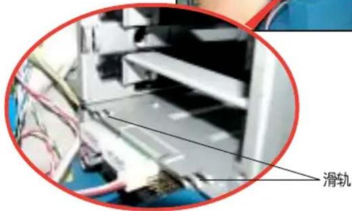
natural_image
Close-up of a computer motherboard with a green arrow pointing to a green component on the left side (no visible text or symbols)2.10.4 软驱

natural_image
Close-up of a hand inserting a USB into a server rack with a green circular arrow indicating the cable (no text or symbols visible)natural_image
Close-up of server rack with a green arrow pointing to a stack of equipment (no visible text or symbols)natural_image
Close-up of server rack with multiple drive bays and a red oval highlighting a component (no visible text or symbols)请依照以下的步骤重新安装软驱:
natural_image
Close-up of server racks with a red cable and connector, no visible text or symbols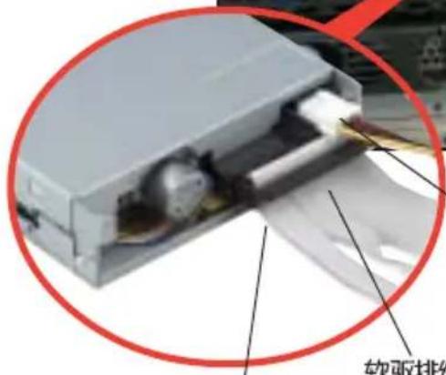
红线位置对准针脚 1
软驱电源适配器
natural_image
Close-up of server rack with ventilation slots and a green arrow pointing to a component (no visible text or symbols)natural_image
Close-up of a hand inserting a USB into a server rack with a green circular arrow indicating rotation (no text or symbols visible)2.10.5 前置输出/入面板

natural_image
Close-up of a hand using a screwdriver to adjust or install a server rack (no visible text or symbols)natural_image
Close-up of a hand inserting into a computer motherboard with a green arrow indicating the process (no text or symbols visible)natural_image
Close-up of an electronic device casing with green circuit board and a green arrow indicating rotation (no text or symbols visible)natural_image
Close-up of a green electronic circuit board inside a gray plastic housing, with a green arrow indicating rotation (no text or symbols visible)natural_image
Close-up of a hand inserting a green plastic component into a computer tower case (no visible text or symbols)natural_image
Close-up of a hand inserting a USB into a server rack, showing a green arrow indicating the process (no text or symbols visible)2.10.6 机箱底座垫片与滚轮
natural_image
Close-up of a computer monitor with a black circular button and a pink screwdriver inserted, no visible text or symbolsnatural_image
Close-up of a hand adjusting a black circular button with a green arrow indicating rotation (no text or symbols visible)natural_image
Close-up of a hand holding a black circular component with metallic parts, no visible text or symbols
natural_image
Close-up of a hand using a screwdriver to adjust a mechanical component (no visible text or symbols)2.10.7 电源
natural_image
Close-up of a computer power drive casing with a mesh fan and indicator panel (no visible text or symbols)natural_image
Close-up of a server rack unit with two ports and two circular buttons (no visible text or labels)natural_image
Close-up of a server rack unit with three ports and indicator lights (no visible text or labels)natural_image
Close-up of hands installing a computer tower fan into a rack, with a green arrow indicating the component (no text or symbols visible)natural_image
Close-up of hands installing or adjusting a computer drive into an open storage unit (no visible text or symbols)natural_image
Close-up of hands holding a CD-ROM drive with a green arrow indicating the next component (no visible text or symbols)
natural_image
Back view of a computer power supply unit showing fan, drive, and socket (no visible text or symbols)锁钩对准孔位
natural_image
Close-up of hands installing a computer tower drive into a rack, showing fan and socket components (no text or symbols visible)natural_image
Back view of a server rack with three ports and four buttons, marked by red circles (no visible text or symbols)natural_image
Hand pointing at a computer tower with visible drive bays and power socket (no text or symbols)natural_image
Computer tower case with visible power lines and ventilation grilles (no text or symbols)
natural_image
Hand pointing at a computer tower module with visible drive bays and fan (no text or symbols)natural_image
Back view of a server rack with three ports and four circular annotations highlighting ports (no readable text or symbols)
natural_image
Illustration of a desktop computer tower with multiple drive bays and ventilation slots (no text or symbols)3.1 安装第二组 SCSI 硬盘槽

natural_image
Close-up of a computer tower drive showing internal components and a hand inserting a cable (no text or symbols visible)硬盘槽固定扣
natural_image
Close-up of hands installing or adjusting a computer tower case with visible internal components (no text or symbols)natural_image
Hand inserting a component into a computer drive (no visible text or symbols)natural_image
Hand using a screwdriver to adjust or install electronic components in a rack (no visible text or symbols)
natural_image
Computer motherboard with visible CPU socket, RAM slots, and circuit board (no readable text or symbols)natural_image
Computer motherboard with visible circuit board and computer monitor (no readable text or symbols)
natural_image
Hand holding a mechanical component inside a transparent enclosure, with a green arrow pointing to a component (no visible text or symbols)natural_image
Close-up of a computer tower with a green circular arrow indicating refresh or move, no visible text or symbols3.3 升级双电源或备援式电源
natural_image
Close-up of hands operating a laptop computer with visible CPU socket and motherboard (no text or symbols)natural_image
Close-up of a hand inserting a CD into a computer drive into an open drive (no visible text or symbols)- 将电源上的电源适配器,安装电源盒中。
natural_image
Computer tower with visible power supply unit and cable rack (no text or symbols)natural_image
Close-up of a computer tower with visible CPU socket and power cord, partially held by a hand adjusting its cable (no text or symbols)natural_image
Close-up of a computer tower case with visible drive bays and power grid (no text or symbols)natural_image
Interior view of a server rack unit with multiple ports and mounting holes (no visible text or labels)3.4 安装一组电源模组
natural_image
Hand inserting a computer into a server rack unit (no visible text or labels)natural_image
Close-up of a computer tower with visible CPU socket and ventilation slots, held by hand (no text or symbols)natural_image
Close-up of a computer tower with visible drive bays and fan slots, held by hand (no text or symbols)natural_image
Close-up of a computer tower with visible drive bays and fan cooling (no text or symbols)- 完成安装,就如同右图所示。
natural_image
Close-up of a computer power supply unit with cooling fans and drive bays (no visible text or labels)3.5 将系统安装于机架上
3.5.1 拆除机箱上盖
请依照以下的步骤来拆除机箱上盖:
natural_image
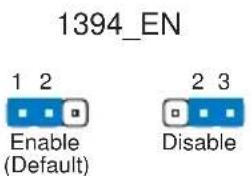
Illustration of a desktop computer tower with four drive bays and a blue abstract background (no text or symbols)4.1 主板结构图
主板元件说明
| 开关与跳线选择区 | 说明 | 页数 |
| 1. Keyboard power | 键盘唤醒功能(3-pin KBPWR) | 4-4 |
| 2. RAID controller setting | RAID 功能控制设置(3-pin RAID_EN1) | 4-4 |
| 3. USB device wake-up | USB 设备唤醒功能(3-pin USBPW12, USBPW34) | 4-5 |
| 4. CPU external frequency setting | CPU 外频设置(3-pin J1) | 4-5 |
| 5. Clear RTC RAM | COMS 组合数据清除选择帽(3-pin CLRTC1) | 4-6 |
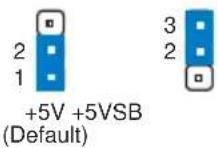
| 6. IEEE 1394 setting | IEEE1394 设置(3-pin 1394_EN) | 4-7 |
| 7. CPU fan pin selection | CPU 风扇选择(3-pin FM_CPU1,FM_CPU2) | 4-7 |
| 内部连接插座\接口\接针 | 说明 | 页数 |
| 1. Floppy disk connector | 软驱插座(34-1 pin FLOPPY1) | 4-8 |
| 2. Serial ATA connectors | SATA 插座(7-pin SATA1/SATA2) | 4-8 |
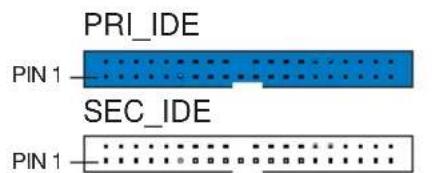
| 3. IDE connectors | IDE 设备插座(40-1 pin PRI_IDE1[蓝色],SEC_IDE[白色]) | 4-9 |
| 4. GAME / MIDI connector | IDE 设备插座(16-1 pin GAME1) | 4-9 |
| 5. IEEE 1394 connector | IEEE 1394 插座(10-1 pin IE 1394_1) | 4-10 |
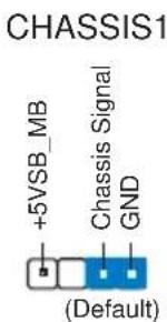
| 6. Chassis intrusion connector | 机箱开启警示排针(4-1 pin CHASSIS1) | 4-10 |
| 7. Serial ATA RAID connector | SATA RAID插座(7-pin SATA_RAID1/2) | 4-11 |
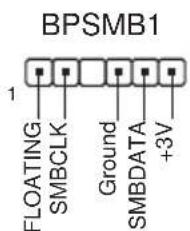
| 8. Backplane SMBus connector | 背板 SMBus 接针(6-1 pin BPSMB1) | 4-11 |
| 9. Power connectors | 电源插座(24-pin ATXPWR,8-pin ATX12V1) | 4-12 |
| 10. Hard disk activity LED connector | 硬盘动作指示灯号连接排针(2-pin IDELED) | 4-12 |
| 11. Front panel audio connector | 前面板音频连接排针(10-1 pin FP_AUDIO1) | 4-13 |
| 12. Internal audio connectors | 内置音频信号接收插槽(4-pin CD1,AUX1,MODEM1) | 4-13 |
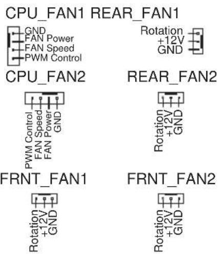
| 13. CPU and system fan connectors | 处理器与系统风扇插座(3-pin CPU_FAN1/2,REAR_FAN1/2,FRNT_FAN1/2) | 4-14 |
| 14. System panel connector | 系统控制面板连接排针(20-pin PANEL) | 4-14 |
| - System Power LED | 系统电源指示灯连接排针(3-pin PLED) | 4-15 |
| - Message LED | 信息指示灯排针(2-pin MLED) | 4-15 |
| - System warning speaker | 机箱音箱连接排针(4-pin SPKR) | 4-15 |
| - Hard disk activity | 硬盘动作指示灯号连接排针(2-pin HD_LED) | 4-15 |
| - Power switch / Soft-off switch | 电源或软开机开关连接排针(2-pin PWR_SW) | 4-15 |
| - Reset switch | 软开机开关连接排针(2-pin RESET) | 4-15 |
| - System Management Interrupt | 系统管理中断连接排针(2-pin SMI) | 4-15 |
4.2 跳线选择区
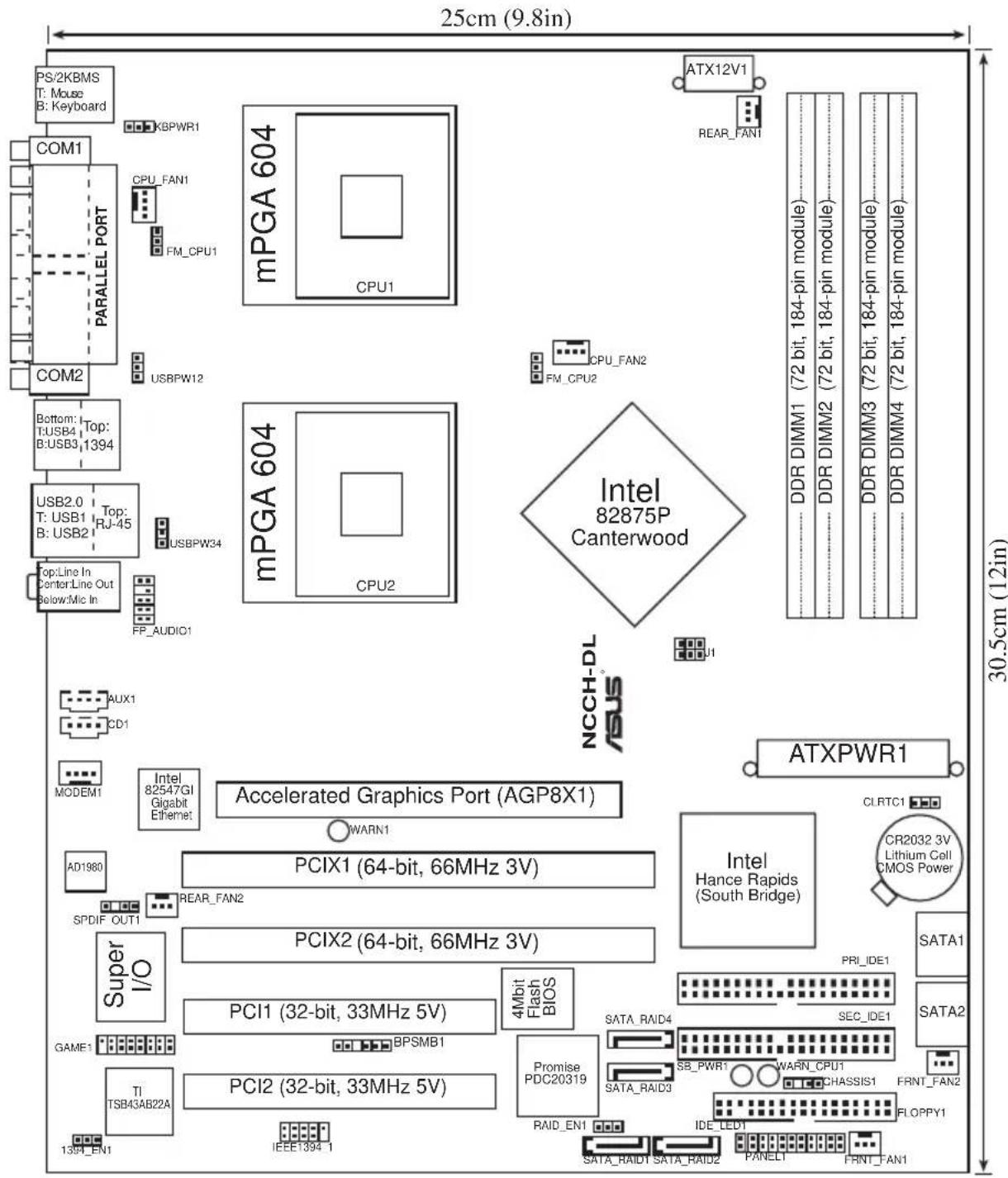
1. 键盘唤醒功能设置 (3-pin KBPWR1)
NCCH-DL USB device wake up
USBPW12
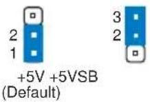
USBPW34

J1
246

1 3 5
Auto-detect CPU FSB (Default)
246

135
100 MHz
246

1 3 5
133 MHz
246

1 3 5
166 MHz
246

1 3 5
200 MHz
NCCH-DL CPU external frequency selection
- CPU 风扇排针设置 (3-pin FM_CPU1, FM_CPU2)
- IEEE 1394 插槽设置 (3-pin 1394_EN)
4.3 元件与外围设备的连接
NCCH-DL IDE connectors
NCCH-DL Chassis intrusion connector
- 串行 ATA 磁盘数组设备连接插座 (7-pin SATA_RAID1, SATA_RAID2)
NCCH-DL SMBus Connector
- SSI 规格主板电源插座 (24-pin ATXPWR, 8-pin ATX12V)
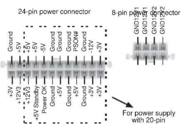
NCCH-DL ATX power connectors
FP_AUDIO1

NCCH-DL Front panel audio connector
Modem-Out Ground Ground Modem-In
MODEM1
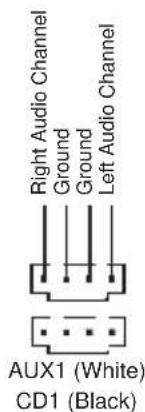
NCCH-DL Internal audio connectors
- 中央处理器/机箱/电源 风扇电源插座 (4-pin CIIA_FAN1/2, 3-pin REAR_FAN1/2, 3-pin FRNT_FAN1/2)
NCCH-DL Fan connectors

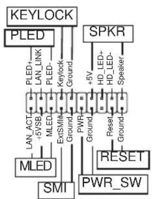
flowchart
graph TD
    A["KEYLOCK"] --> B["PLED"]
    A --> C["SPKR"]
    B --> D["LAN_ACT"]
    B --> E["LAN_LINK"]
    B --> F["LED"]
    B --> G["Ground"]
    C --> H["HD_LED+"]
    C --> I["HD_LED-"]
    C --> J["Speaker"]
    D --> K["LAN_ACT"]
    D --> L["LAN_LINK"]
    D --> M["LED"]
    D --> N["ExtSMink"]
    D --> O["Ground"]
    E --> P["PWR"]
    E --> Q["PWR_SW"]
    F --> R["Ground"]
    G --> S["Ground"]
    H --> T["RESET"]
    I --> U["Ground"]
    J --> V["Ground"]
    K --> W["MLED"]
    L --> X["SMI"]
natural_image
Illustration of a desktop computer tower with multiple drive bays and indicator lights (no text or symbols)5.1 管理、升级您的 BIOS 程序


存储备份原始 BIOS 档
EZFlash starting BIOS update
Checking for floppy...
Floppy found!
Reading file "NCCH-DL.rom". Completed.
Start erasing......|
Start programming...|
Flashed successfully. Rebooting.
![Time (hh:mm:ss) 11: 10 : 30 Date (mm:dd:yy) Wed, Jun 30 2004 Legacy Diskette A [1.44M, 3.5 in.] Floppy 3 Mode Support [Disabled] ► Primary IDE Master [None] ► Primary IDE Slave [None] ► Secondary IDE Master [None] ► Secondary IDE Slave [None] ► Third IDE Master [None] ► Fourth IDE Master [None] Base Memory 640K Extended Memory 261120K Total Memory 26114K Select Menu Item Specific Help ► Change the day, month, year and century.](/content/2026/06/1166803/images/b96636e9640385e34123f59f4b2773eea886a8c9a2a439e3e34aaf5d5be6aa4b.jpg)
Time [hh:mm:ss]
Legacy Diskette A [1.44M, 3.5 in.]
本项目存储了软驱的相关信息,设置值有:[None] [360K, 5.25 in.] [1.2M, 5.25 in.] [720K, 3.5 in.] [1.44M 3.5 in.] [2.88M, 3.5 in.]。
Floppy 3 Mode Support [Disabled]
Base/Extended/Total Memory [xxxK]
Primary IDE [Auto]
Manual detecting an IDE drive

5.3.2 Primary IDE Slave
5.3.3 Secondary IDE Master
5.3.4 Secondary IDE Slave
5.3.5 Third IDE Master
Extended IDE Drive [Auto]
5.3.6 Fourth IDE Master
5.4.1 高级 BIOS 功能
| Advanced BIOS Features | Select Menu |
| Chipset Vcore Voltage [+1.6V] DRAM Vcore Voltage [+2.6V] | Item Specific Help ▶ Press [ENTER] to adjust Chipset Vcrore voltage. |
| F1 Help F1 Select Item -2 Change Value +5 Setup Defaults DIG Train ++ Select Menu Enter Select SubMenu +10 Save and Exit | |

Chipset Vcore Voltage [+1.6V]
DRAM Vcore Voltage [+2.6V]
| CPU Configuration | Select Menu |
| CPU L1 & L2 Cache [Enabled] Hyper-Threading Technology [Enabled] | Item Specific Help ▶ Disable/Enable CPU L1/ L2 cache. |
CPU L1 & L2 Cache [Enabled]
| Memory Configuration | Select Menu |
| DRAM Frequency [Auto] Memory Timing Selectable [By SPD] Cache Latency Time 2 Active to Precharge Delay 6 DRAM RAS# to CAS# Delay 3 DRAM RAS# Precharge 3 Memory Parity Check Enabled | Item Specific Help ▶ Set DRAM Frequency. |
| F1 Help F2 Select Item -24. Divide Value ESC Unit -- Select New Enter: Select SubMn | F5 Setup Default F10 Save and Cut |
DRAM Frequency [Auto]
本选项设置 DRAM 操作频率。设置值有:[DDR266] [DDR333] [DDR400] [Auto]
Memory Timing Selectable [By SPD]
CAS Latency Time [2]
Active to Precharge Delay [6]
DRAM RAS# to CAS# Delay [3]
Memory Parity Check [Enabled]
| Chipset | Select Menu |
| ▶ AGP Bridge Configuration ▶ Frequency/Voltage Control System BIOS Cacheable [Enabled] Video BIOS Cacheable [Disabled] Init Display First [AGP Slot] Auto Detect PCI Clk [Enabled] Spread Spectrum [+/- 0.50%] | Item Specific Help ▶ Press Enter to set. |
System BIOS Cacheable [Enabled]
Spread Spectrum [-0.5%]
本项目可以让您选择展频时钟生成器的整体比率。设置值有:[Disabled] [+ / - 0.1%] [+ / - 0.2%] [+ / - 0.3%] [+ / - 0.4%] [+ / - 0.5%] [+ / - 0.6%] [+ / - 0.7%] [+ / - 0.8%] [+ / - 0.9%] [+ / - 1.0%]
AGP Bridge Configuration
| AGP Bridge Configuration | Select Menu |
| AGP Aperture Size [128] | Item Specific Help ▶►►Size of the AGP Aperture. |
| F1:Help T1:Select Item √- Change Value #5:Setup Defaults EIC:Exit #-Select Menu Enter: Select SubMenu F10:Save and Exit | |
AGP Aperture Size [128]
Frequency/Voltage Control
| Frequency/Voltage Control | Select Menu |
| CPU Clock [200MHz] CPU Clock Ratio [14 X] | Item Specific Help ▶▶▶ Set CPU Frequency. |
| F1:Help T2:Select Item -/- Change Value F5: Setup Defaults E3: East +: Select Menu Enter: Select SubMenu F10: Save and Cut | |

CPU Clock Ratio [18 X]
Report System Booting [Enabled]
CSA LAN (Giga-LAN) [Enabled]
Operating Mode [IDE]
| SuperIO Device | Select Menu |
| Serial Port1 Address [3F8/IRQ4] Serial Port2 Address [2F8/IRQ3] Onboard Parallel Port [378/IRQ7] Parallel Port Mode [SPP] EPP Mode Select EPP1.7 ECP Mode Use DMA 3 | Item Specific Help ▶▶▶ Set Base I/O address for serial port 1. |
| F1:Help F2:Select Items F3:Change Value F4:Setup Defaults ESC/Estl #:Select Menu Enter: Select SubMenu F5:Save and Exit | |
Serial Port 1 Address [3F8/IRQ4]
Serial Port 2 Address [2F8/IRQ3]
本项目可以让您设置串口的基础地址。设置值有:[Disabled] [3F8/IRQ4] [2F8/IRQ3] [3E8/IRQ4] [2E8/IRQ3] [Auto]
Onboard Parallel Port [378/IRQ7]
Parallel Port Mode [SPP]
本项目让您选择并口的模式。设置值有:[SPP] [EPP] [ECP] [ECP+EPP] [Norma1]
EPP Mode Select [EPP1.7]
Game Port Address [201]
MIDI Port Address [330]
Serial ATA Port0 Mode [Primary Master] Serial ATA Port1 Mode [Primary Slave]
| PCIPnP | Select Menu |
| Reset Configuration Data [Disabled] | Item Specific Help ▶ |
| Resources Controlled By [Auto] | Default is Disabled. |
| IRQ Resources | Select Enabled to reset Extended System |
| PCI/VGA Pallete Snoop [Disabled] | Configuration Data (ESCD) upon exiting |
| INT Pin 1 Assignment [Auto] | Setup, if you installed a new add-on card and the system cannot boot due to a serious conflict in system configuration. |
| INT Pin 2 Assignment [Auto] | |
| INT Pin 3 Assignment [Auto] | |
| INT Pin 4 Assignment [Auto] | |
| INT Pin 5 Assignment [Auto] | |
| INT Pin 6 Assignment [Auto] | |
| INT Pin 7 Assignment [Auto] | |
| INT Pin 8 Assignment [Auto] | |
| FS Setup Defaults F10 Save and Exit. | |
Reset Configuration Data [Disabled]
Resources Controlled By [Auto]
INT Pin 1\~8 Assignment [Auto]
本项目可让您选择适当的中断地址给特定设备,避免冲突发生。设置值有:[Auto] [3] [4] [5] [7] [9] [10] [11] [12] [14] [15]
IRQ Resources

| PCIPnP | Select Menu |
| Reset Configuration Data [Disabled] | Item Specific Help ▶ |
| Resources Controlled By [Manual] ►IRQ Resources | When resources are controlled manually, assign each system interrupt a type depending on the type of device using the interrupt. |
| PCI/VGA Pallete Snoop [Disabled] | |
| INT Pin 1 Assignment [Auto] | |
| INT Pin 2 Assignment [Auto] | |
| INT Pin 3 Assignment [Auto] | |
| INT Pin 4 Assignment [Auto] |
| IRQ Resources | Select Menu | |
| IRQ-3 assigned to [PCI Device] | Item Specific Help ▶▶▶ | |
| IRQ-4 assigned to [PCI Device] | Legacy ISA for devices compliant with the original PC AT bus specification, PCI/ISA PnP for devices compliant with the Plug and Play standard whether designed for PCI or ISa bus architecture. | |
| IRQ-5 assigned to [PCI Device] | ||
| IRQ-7 assigned to [PCI Device] | ||
| IRQ-9 assigned to [PCI Device] | ||
| IRQ-10 assigned to [PCI Device] | ||
| IRQ-11 assigned to [PCI Device] | ||
| IRQ-12 assigned to [PCI Device] | ||
| IRQ-14 assigned to [PCI Device] | ||
| IRQ-15 assigned to [PCI Device] | ||
| F1:Help 12:Select Item 3/- Change Value F5:Setup Defaults F10:Save and Cut | ||
| F1:Help 12:Select Item 3/- Change Value F5:Setup Defaults F10:Save and Cut | ||
| F1:Help 12:Select Item 3/- Change Value F5:Setup Defaults F10:Save and Cut | ||
| F1:Help 12:Select Item 3/- Change Value F5:Setup Defaults F10:Save and Cut | ||
IRQ-xx assigned to [PCI device]
| USB Configuration | Select Menu |
| USB Controller [Enabled] USB 2.0 Support [Enabled] USB Legacy Mode Support [Enabled] | Item Specific Help ▶ Configures the USB controller. |
| F1 Help T4 Select Item - / Change Value F5 Setup Defaults E6 Exit ex Select Menu Enter Select SetMenu F10 Save and Cut | |
USB Controller [Enabled]
USB 2.0 Support [Enabled]
USB Legacy Mode Support [Enabled]
ACPI APIC Support [Enabled]
ACPI Suspend Type [S1&S3]
| APM Configuration | Select Menu |
| Power Management [User Define] HDD Power Down [Disabled] Suspend Mode [Disabled] Suspend Type [Stop Grant] Restore on AC Power Loss [Power Off] Video Off Method [DPMS] Video Off In Suspend [Yes] MODEM Use IRQ [3] Soft-Off by PWR-BTN [Instant-Off] USB Wake-Up from S3(S4) [Disabled] Power On By PCI Devices [Enabled] Power On By External Modem [Enabled] POWER ON Function [Button Only] KB Power On Password Enter Hot Key Power ON Ctrl-F1 Resume By Alarm [Disabled] Date (of Month) Alarm 0 Time (hh:mm:ss) Alarm 0 : 0 : 0 | Item Specific Help ▶ This field allows you to set the automatic power saving features. |
Power Management [User Define]
本项目让您设置自动能源节电功能。设置值有:[User Define] [Min. Saving] [Max. Saving]
HDD Power Down [Disabled]
Suspend Type [Stop Grant]
Restore on AC Power Loss [Power Off]
若设置为 [Power Off],则当系统在电源中断之后电源将维持关闭状态。若设置为 [Power On],当系统在电源中断之后重新开启。若设置为 [Last State],会将系统设置恢复到电源末中断之前的状态。设置值有:[Power Off] [Power On] [Last State]
Video Off Method [DPMS]
Soft-Off by PWR-BTTN [Instant-Off]
USB Wake-Up from S3(S4) [Disabled]
Power On by PCI Card [Enabled]
Power On by External Modem [Enabled]
Hot Key Power On Password [Ctrl-F1]
Resume by Alarm [Disabled]
Date (of Month) Alarm [0]
System Target Temperature [50]
CPU1 Target Temperature [60]
System Target Temperature [60]
5.6.1 當動設備順序Priority
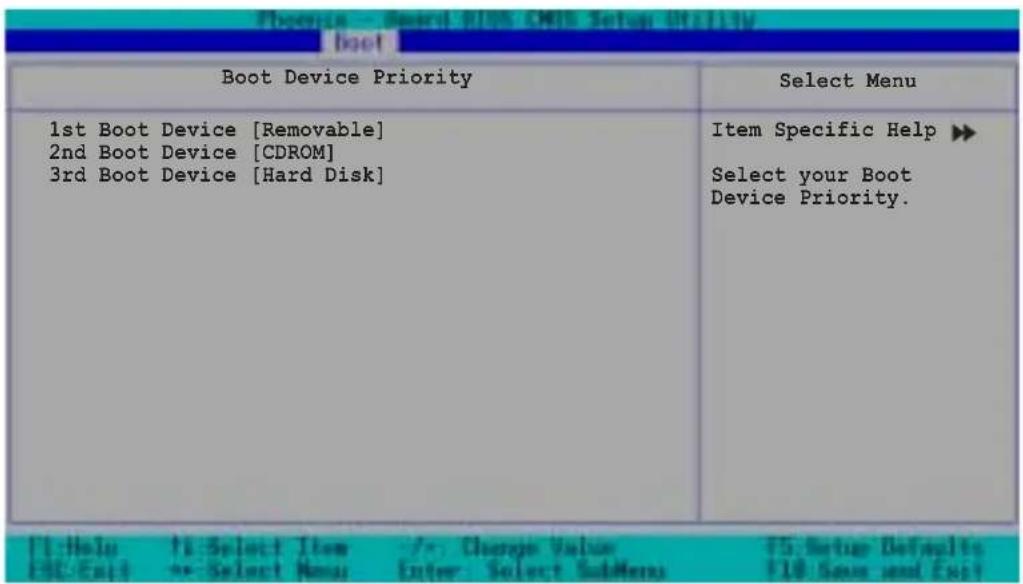
1st Boot Device [Removable]
1nd Boot Device [CDROM]
3rd Boot Device [Hard Disk]
| Hard Disk Boot Priority | Select Menu |
| 1. Bootable Add-in Cards | Item Specific Help ▶ Use <up> or <down> arrow to select a device, then press <+> to move it up, or <-> to move it down the list. Press <ESC> to exit this menu. |
| F2:Help F1:Select Item /+: Change Value F5: Setup Defaults ESC:Exit ex:Select New Enter: Select BobMenu F1F: Save and Exit | |
5.6.3 Removable Device Priority
| Removable Device Priority | Select Menu |
| 1. Floppy Disks | Item Specific Help ▶ Use <up> or <down> arrow to select a device, then press <+> to move it up, or <-> to move it down the list. Press <ESC> to exit this menu. |
5.6.4 畸動選項設置 Configuration
| Boot Settings Configuration | Select Menu |
| Boot Other Device [Enabled] Quick Power On Self Test [Enabled] Halt On [All Errors] Case Open Warning [Enabled] Boot Up Floppy Seek [Enabled] Boot Up NumLock Status [On] Typematic Rate Setting [Disabled] Typematic Rate (Chars/Sec) 6 Typematic Delay (Msec) 250 Full Screen Logo Show [Enabled] | Item Specific Help ▶ Select your Boot Device Priority. |
Boot Other Device [Enabled]
Quick Power On Self Test [Enabled]
Typematic Rate(Chars/Sec) [6]
Typematic Delay(Msec) [250]
Full Screen Logo Show [Enable]
本项目用来开启或关闭华硕 My1ogo2TM 功能。设置值有:[Disabled] [Enabled]
![ASUS AP1720-E2 - Full Screen Logo Show [Enable] - 1](/content/2026/06/1166803/images/2f22916fba21af20d4acbbbe4149c838ecee31a8cc129109a8676a6b8677b42c.jpg)
| Security | Select Menu |
| Supervisor Password Clear User Password Clear Password Check [Setup] | Item Specific Help ▶ Supervisor password control full access. |
Supervisor Password [Clear]
User Password [Clear]
Password Check [Setup]
| Exit & Save Changes Exit & Discard Changes Load Setup Defaults Discard Changes | Select Menu |
| Item Specific Help ▶ This option saves data to CMOS before exiting Setup. |