
RS704D-E6/PS8 - Server ASUS - Free user manual and instructions
Find the device manual for free RS704D-E6/PS8 ASUS in PDF.

| Product Type | Rackmount Server |
| Model | ASUS RS704D-E6/PS8 |
| Form Factor | 2U Rack |
| Dimensions (W x D x H) | 19 x 30.5 x 3.5 inches (approx.) |
| Weight | ~45 lbs (20.4 kg) |
| Power Supply | Two redundant 1200W hot-swap PSUs |
| Processor Support | Dual Intel Xeon E5-2600 v3/v4 (LGA 2011-3) |
| Chipset | Intel C612 |
| Memory | 16 DIMM slots, up to 1TB DDR4 ECC RDIMM/LRDIMM |
| Storage | 8x 3.5" hot-swap SATA/SAS bays (up to 12 with optional) |
| Expansion Slots | 7x PCIe 3.0 (x16/x8) |
| Networking | Dual Intel I210AT Gigabit LAN |
| Management | ASMB9-iKVM for remote management |
| Cooling | 4x 80mm hot-swap fans |
| RAID Support | Integrated SATA RAID 0/1/10/5 (optional HW RAID) |
| Security | Chassis intrusion detection, TPM header |
| Maintenance | Tool-less access to internal components, LED diagnostics |
| Spare Parts | Power supply, fan modules, drive caddies available from ASUS |
| General Information | Designed for data centers, supports virtualization |
Frequently Asked Questions - RS704D-E6/PS8 ASUS
User questions about RS704D-E6/PS8 ASUS
0 question about this device. Answer the ones you know or ask your own.
Ask a new question about this device
Download the instructions for your Server in PDF format for free! Find your manual RS704D-E6/PS8 - ASUS and take your electronic device back in hand. On this page are published all the documents necessary for the use of your device. RS704D-E6/PS8 by ASUS.
USER MANUAL RS704D-E6/PS8 ASUS
natural_image
Front view of a server rack unit with multiple drive bays and ventilation slots (no visible text or labels)E5318
First Edition
March 2010
Copyright © 2010 ASUSTeK COMPUTER INC. All Rights Reserved.
No part of this manual, including the products and software described in it, may be reproduced, transmitted, transcribed, stored in a retrieval system, or translated into any language in any form or by any means, except documentation kept by the purchaser for backup purposes, without the express written permission of ASUSTeK COMPUTER INC. ("ASUS").
ASUS provides this manual “as is” without warranty of any kind, either express or implied, including but not limited to the implied warranties or conditions of merchantability or fitness for a particular purpose. In no event shall ASUS, its directors, officers, employees, or agents be liable for any indirect, special, incidental, or consequential damages (including damages for loss of profits, loss of business, loss of use or data, interruption of business and the like), even if ASUS has been advised of the possibility of such damages arising from any defect or error in this manual or product.
Specifications and information contained in this manual ae furnished for informational use only, and are subject to change at any time without notice, and should not be construed as a commitment by ASUS. ASUS assumes no responsibility or liability for any errors or inaccuracies that may appear in this manual, including the products and software described in it.
Product warranty or service will not be extended if: (1) the product is repaired, modified or altered, unless such repair, modification of alteration is authorized in writing by ASUS; or (2) the serial number of the product is defaced or missing.
Products and corporate names appearing in this manual may or may not be registered trademarks or copyrights of their respective companies, and are used only for identification or explanation and to the owners' benefit, without intent to infringe.
Contents
Notices ...... vii
Safety information ...... viii
About this guide ix
Chapter 1: Product introduction
1.1 System package contents 1-2
1.2 Serial number label 1-3
1.3 System specifications 1-4
1.4 Front panel features 1-6
1.5 Rear panel features 1-7
1.6 Internal features 1-8
1.7 LED information 1-10
1.7.1 Front panel LEDs 1-10
1.7.2 LAN (RJ-45) LEDs 1-10
1.7.3 HDD status LED 1-10
Chapter 2: Hardware setup
2.1 Chassis cover 2-2
2.2 Central Processing Unit (CPU) 2-3
2.2.1 Installing the CPU 2-3
2.2.2 Installing the CPU heatsink and airduct.... 2-6
2.3 System memory 2-7
2.3.1 Overview 2-7
2.3.2 Memory Configurations.... 2-8
2.3.3 Installing a DIMM 2-9
2.3.4 Removing a DIMM 2-9
2.4 Hard disk drives 2-10
2.5 Expansion slot 2-11
2.5.1 Installing an expansion card to the riser card bracket....2-11
2.5.2 Configuring an expansion card 2-12
2.6 Cable connections 2-13
2.7 Removable/optional components 2-14
2.7.1 Replacing system fans.... 2-14
2.7.1 Replacing system fans.... 2-14
2.7.1 Replacing system fans.... 2-14
2.7.1 Replacing system fans.... 2-14
2.7.1 Replacing system fans.... 2-14
2.7.1 Replacing system fans.... 2-14
2.7.1 Replacing system fans.... 2-14
2.7.1 Replacing system fans.... 2-14
2.7.1 Replacing system fans.... 2-14
2.7.1 Replacing system fans.... 2-14
2.7.1 Replacing system fans.... 2-14
2.7.1 Replacing system fans.... 2-14
2.7.1 Replacing system fans.... 2-14
2.7.1 Replacing system fans.... 2-14
2.7.1 Replacing system fans.... 2-14
2.7.1 Replacing system fans.... 2-14
2.7.1 Replacing system fans.... 2-14
2.7.1 Replacing system fans.... 2-14
2.7.2 Replacing power supply units 2-15
2.7.2 Replacing power supply units 2-15
2.7.2 Replacing power supply units 2-15
2.7.2 Replacing power supply units 2-15
2.7.2 Replacing power supply units 2-15
2.7.2 Replacing power supply units 2-15
2.7.2 Replacing power supply units 2-15
2.7.2 Replacing power supply units 2-15
2.7.2 Replacing power supply units 2-15
2.7.2 Replacing power supply units 2-15
2.7.1 Replacing system fans.... 2-14 2.7.2 Replacing power supply units.... 2-15
2.7.2 Replacing power supply units 2-15
2.7.2 Replacing power supply units 2-15
2.7.2 Replacing power supply units 2-15
2.7.3 Installing ASMB4 series management board (optional) 2-16
2.7.3 Installing ASMB4 series management board (optional) 2-16
2.7.3 Installing ASMB4 series management board (optional) 2-16
2.7.3 Installing ASMB4 series management board (optional) 2-16
2.7.3 Installing ASMB4 series management board (optional) 2-16
2.7.3 Installing ASMB4 series management board (optional) 2-16
2.7.3 Installing ASMB4 series management board (optional) 2-16
2.7.3 Installing ASMB4 series management board (optional) 2-16
2.7.3 Installing ASMB4 series management board (optional) 2-16
2.7.3 Installing ASMB4 series management board (optional) 2-16
2.7.3 Installing ASMB4 series management board (optional) 2-16
2.7.3 Installing ASMB4 series management board (optional) 2-16
2.7.3 Installing ASMB4 series management board (optional) 2-16
2.7.3 Installing ASMB4 series management board (optional) 2-16
2.7.3 Installing ASMB4 series management board (optional) 2-16
2.7.3 Installing ASMB4 series management board (optional) 2-16
2.7.3 Installing ASMB4 series management board (optional) 2-16
2.7.3 Installing ASMB4 series management board (optional) 2-16
2.7.3 Installing ASMB4 series management board (optional) 2-16
2.7.4 Installing ASUS PIKE Riser Card (optional).... 2-17
Contents
Chapter 3: Installation options
3.1 Rackmount rail kit items (optional) 3-2
3.2 Attaching the rails to the server 3-2
3.3 Attaching the rack rails 3-3
3.4 Rackmounting the server 3-4
Chapter 4: Motherboard Info
4.1 Motherboard layout 4-2
4.2 Jumpers 4-6
4.3 Internal connectors 4-12
4.4 Internal LEDs 4-20
Chapter 5: BIOS setup
5.1 Managing and updating your BIOS 5-2
5.1.1 AFUDOS utility 5-2
5.1.2 ASUS CrashFree BIOS 3 utility 5-4
5.2 BIOS setup program 5-5
5.2.1 BIOS menu screen 5-6
5.2.2 Menu bar 5-6
5.2.3 Navigation keys 5-6
5.2.4 Menu items 5-7
5.2.5 Sub-menu items 5-7
5.2.6 Configuration fields 5-7
5.2.7 Pop-up window 5-7
5.2.8 Scroll bar 5-7
5.2.9 General help 5-7
5.3 Main menu 5-8
5.3.1 System Time 5-8
5.3.2 System Date 5-8
5.3.3 SATA1-4 5-8
5.3.4 IDE Configuration.... 5-10
5.3.5 AHCI Configuration 5-11
5.3.6 System Information 5-12
5.4 Advanced menu 5-13
5.4.1 CPU Configuration 5-13
5.4.2 Chipset Configuration 5-17
Contents
5.4.3 Legacy Device Configuration 5-21
5.4.4 USB Configuration 5-22
5.4.5 PCIPnP Configuration.... 5-23
5.4.6 Power On configuration 5-24
5.4.7 Event Log Configuration 5-25
5.4.8 Hardware Monitor 5-26
5.4.9 I/O Virtualization....5-27
5.4.10 PCI Express Configuration.... 5-27
5.4.11 ACPI Configuration 5-28
5.5 Server menu 5-30
5.5.1 Remote Access Configuration.... 5-30
5.6 Boot menu 5-32
5.6.1 Boot Device Priority 5-32
5.6.2 Hard Disk Drives; CDROM Drives 5-32
5.6.3 Boot Settings Configuration 5-33
5.6.4 Security 5-34
5.7 Exit menu 5-36
Chapter 6: RAID configuration
6.1 Setting up RAID 6-2
6.1.1 RAID definitions 6-2
6.1.2 Installing hard disk drives.... 6-2
6.1.3 RAID controller selection 6-3
6.1.4 Setting the RAID item in BIOS 6-3
6.2 LSI Software RAID Configuration Utility 6-4
6.2.1 Creating a RAID set 6-5
6.2.2 Adding or viewing a RAID configuration ....6-11
6.2.3 Initializing the virtual drives 6-12
6.2.4 Rebuilding failed drives 6-16
6.2.5 Checking the drives for data consistency 6-18
6.2.6 Deleting a RAID configuration.... 6-21
6.2.7 Selecting the boot drive from a RAID set.... 6-22
6.2.8 Enabling WriteCache 6-23
6.3 Intel ^® Matrix Storage Manager Option ROM Utility 6-24
6.3.1 Creating a RAID set 6-25
Contents
6.3.2 Creating a Recovery set 6-26
6.3.3 Deleting a RAID set 6-28
6.3.4 Resetting disks to Non-RAID 6-29
6.3.5 Recovery Volume Options 6-30
6.3.6 Exiting the Intel ^ Matrix Storage Manager 6-31
6.3.7 Rebuilding the RAID 6-31
6.3.8 Setting the Boot array in the BIOS Setup Utility 6-33
Chapter 7: Driver installation
7.1 RAID driver installation 7-2
7.1.1 Creating a RAID driver disk 7-2
7.1.2 Installing the RAID controller driver 7-5
7.2 Intel ^® chipset device installation 7-17
7.3 LAN driver installation 7-19
7.4 VGA driver installation.... 7-22
7.5 Mellanox ConnectX DDR PCI Gen2 Channel Adapter driver installation (For RS702D-E6/PS8; RS704D-E6/PS8) 7-24
7.5.1 Windows operating system....7-24
7.5.2 Red Hat ^ Enterprise Linux OS 7-27
7.6 Management applications and utilities installation 7-29
7.6.1 Running the support DVD 7-29
7.6.2 Drivers menu.... 7-29
7.6.3 Utilities menu 7-30
7.6.4 Make disk menu.... 7-30
7.6.5 Contact information 7-30
Notices
Federal Communications Commission Statement
This device complies with Part 15 of the FCC Rules. Operation is subject to the following two conditions:
• This device may not cause harmful interference, and
- This device must accept any interference received including interference that may cause undesired operation.
This equipment has been tested and found to comply with the limits for a Class A digital device, pursuant to Part 15 of the FCC Rules. These limits are designed to provide reasonable protection against harmful interference in a residential installation. This equipment generates, uses and can radiate radio frequency energy and, if not installed and used in accordance with manufacturer's instructions, may cause harmful interference to radio communications. However, there is no guarantee that interference will not occur in a particular installation. If this equipment does cause harmful interference to radio or television reception, which can be determined by turning the equipment off and on, the user is encouraged to try to correct the interference by one or more of the following measures:
• Reorient or relocate the receiving antenna.
- Increase the separation between the equipment and receiver.
- Connect the equipment to an outlet on a circuit different from that to which the receiver is connected.
- Consult the dealer or an experienced radio/TV technician for help.

WARNING! The use of shielded cables for connection of the monitor to the graphics card is required to assure compliance with FCC regulations. Changes or modifications to this unit not expressly approved by the party responsible for compliance could void the user's authority to operate this equipment.
Canadian Department of Communications Statement
This digital apparatus does not exceed the Class A limits for radio noise emissions from digital apparatus set out in the Radio Interference Regulations of the Canadian Department of Communications.
This Class A digital apparatus complies with Canadian ICES-003.
REACH
Complying with the REACH (Registration, Evaluation, Authorization, and Restriction of Chemicals) regulatory framework, we publish the chemical substances in our products at ASUS REACH website at http://green.asus.com/english/REACH.htm.
Safety information
Electrical Safety
- Before installing or removing signal cables, ensure that the power cables for the system unit and all attached devices are unplugged.
- To prevent electrical shock hazard, disconnect the power cable from the electrical outlet before relocating the system.
- When adding or removing any additional devices to or from the system, contact a qualified service technician or your dealer. Ensure that the power cables for the devices are unplugged before the signal cables are connected. If possible, disconnect all power cables from the existing system before you service.
- If the power supply is broken, do not try to fix it by yourself. Contact a qualified service technician or your dealer.
Operation Safety
- Servicing of this product or units is to be performed by trained service personnel only.
- Before operating the server, carefully read all the manuals included with the server package.
- Before using the server, make sure all cables are correctly connected and the power cables are not damaged. If any damage is detected, contact your dealer as soon as possible.
- To avoid short circuits, keep paper clips, screws, and staples away from connectors, slots, sockets and circuitry.
- Avoid dust, humidity, and temperature extremes. Place the server on a stable surface.

This product is equipped with a three-wire power cable and plug for the user's safety. Use the power cable with a properly grounded electrical outlet to avoid electrical shock.
Lithium-Ion Battery Warning
CAUTION! Danger of explosion if battery is incorrectly replaced. Replace only with the same or equivalent type recommended by the manufacturer. Dispose of used batteries according to the manufacturer's instructions.
CD-ROM Drive Safety Warning
CLASS 1 LASER PRODUCT
Heavy System
CAUTION! This server system is heavy. Ask for assistance when moving or carrying the system.

DO NOT throw the motherboard in municipal waste. This product has been designed to enable proper reuse of parts and recycling. This symbol of the crossed out wheeled bin indicates that the product (electrical and electronic equipment) should not be placed in municipal waste. Check local regulations for disposal of electronic products.

DO NOT throw the mercury-containing button cell battery in municipal waste. This symbol of the crossed out wheeled bin indicates that the battery should not be placed in municipal waste.
About this guide
Audience
This user guide is intended for system integrators, and experienced users with at least basic knowledge of configuring a server.
Contents
This guide contains the following parts:
1. Chapter 1: Product Introduction
This chapter describes the general features of the server, including sections on front panel and rear panel specifications.
2. Chapter 2: Hardware setup
This chapter lists the hardware setup procedures that you have to perform when installing or removing system components.
3. Chapter 3: Installation options
This chapter describes how to install the optional components and devices into the barebone server.
4. Chapter 4: Motherboard information
This chapter includes the motherboard layout and brief descriptions of the jumpers and internal connectors.
5. Chapter 5: BIOS information
This chapter tells how to change system settings through the BIOS Setup menus and describes the BIOS parameters.
6. Chapter 6: RAID configuration
This chapter provides instructions for setting up, creating and configuring RAID sets using the available utilities.
7 Chapter 7: Driver installation
This chapter provides instructions for installing the necessary drivers for different system components.
Conventions
To make sure that you perform certain tasks properly, take note of the following symbols used throughout this manual.
DANGER/WARNING: Information to prevent injury to yourself when trying to complete a task.
CAUTION: Information to prevent damage to the components when trying to complete a task.
IMPORTANT: Instructions that you MUST follow to complete a task.
NOTE: Tips and additional information to help you complete a task.
Typography
Bold text Indicates a menu or an item to select.
Italics Used to emphasize a word or a phrase.
Example:
Example:
Command Means that you must type the command exactly as shown, then supply the required item or value enclosed in brackets.
Example: At the DOS prompt, type the command line:
format A:/S
References
Refer to the following sources for additional information, and for product and software updates.
1. ASUS Server Web-based Management (ASWM) user guide
This manual tells how to set up and use the proprietary ASUS server management utility.
2. ASUS websites
The ASUS websites worldwide provide updated information for all ASUS hardware and software products. Refer to the ASUS contact information.
Chapter 1
This chapter describes the general features of the server, including sections on front panel and rear panel specifications.

natural_image
Front view of a server rack with multiple drive bays and indicator lights (no visible text or labels)1.1 System package contents
Check your system package for the following items.
| Model Name RS700D-E6/PS8 RS702D-E6/PS8 RS704D-E6/PS8 | ||
| Chassis ASUS R12B 1U Rackmount Chassis | ||
| Motherboard 2 x ASUS Z8NH-D12 Server Board | 2 x ASUS Z8PH-D12/IFB Server Board | 2 x ASUS Z8PH-D12 SE/QDR Server Board |
| Component 2 x 770W Single Power Supply8 x Hot-swap 2.5" HDD trays1 x SAS/SATA2 Backplane2 x PCI Riser Card (ASUS RE16R-R12B)2 x Front I/O Board (ASUS FPB-AR14)1 x Power Distribution Board (ASUS PDB-R12B)8 x System Fans (40mm x 56mm) | 2 x 770W Single Power Supply8 x Hot-swap 2.5" HDD trays1 x SAS/SATA2 Backplane2 x PCI Riser Card (ASUS RE16R-R12B)2 x Front I/O Board (ASUS FPB-R12A)1 x Power Distribution Board (ASUS PDB-R12B)8 x System Fans (40mm x 56mm) | |
| Accessories 1 x RS700D-E6/PS8, RS702D-E6/PS8, RS704D-E6/PS8 User's Guide1 x ASUS ASWM 2.0 User's Guide1 x 55x0 Series Support CD (including ASWM*)1 x Bag of Screws2 x AC Power Cables1 x Semi-ball Bearing Rail Kit | ||
| Optional Items CPU HeatsinkASUS ASMB4-iKVM Remote management cardASUS PIKE Riser Card (RE16R-R12B-PIKE)ASUS PIKE 1064E 4-port SAS RAID cardASUS PIKE 1078 8-port SAS HW RAID cardAnti-virus Software CD | ||
* ASUS System Web-based Management
** The system does not include a USB floppy drive. You may have to use a USB floppy drive when creating a SATA RAID driver disk. Refer to Chapter 7 for details.

If any of the above items is damaged or missing, contact your retailer.
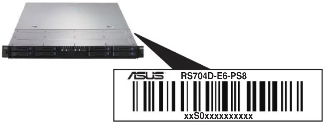
1.2 Serial number label
Before requesting support from the ASUS Technical Support team, you must take note of the product's serial number containing 14 characters such as xxS0xxxxxxxxxx shown as the figure below. With the correct serial number of the product, ASUS Technical Support team members can then offer a quicker and satisfying solution to your problems.
1.3 System specifications
The ASUS RS700D-E6/PS8 is a 1U barebone server system featuring the ASUS Z8NH-D12 server boards. The ASUS RS702D-E6/PS8 is a 1U barebone server system featuring the ASUS Z8PH-D12/IFB server boards. The ASUS RS704D-E6/PS8 is a 1U barebone server system featuring the ASUS Z8PH-D12 SE/QDR server boards. The servers support Intel ^® LGA1366 Xeon ^® 5500 series processors, plus other latest technologies through the chipsets onboard.
| Model Name RS700D-E6/PS8 RS702D-E6/PS8 RS704D-E6/PS8 | ||||
| Processor / System Bus | 2 x Socket LGA1366 per Node | |||
| 32nm Six/Quad-Core Intel® Xeon® Processors- Quad-Core Intel® Xeon® X5500, X5600 Series (95W)- Dual/Quad-Core Intel® Xeon® E5500, E5600 Series (80W)- Quad-Core Intel® Xeon® L5500, L5600 Series (60W/40W) | ||||
| QPI 4.8 / 5.86 / 6.4 GT/s | ||||
| Core Logic | - Intel® 5500 I/OHub- Intel® ICH10R I/OController | - Intel® 5520 I/OHub- Intel® ICH10R I/OController- MellanoxConnectXMT25408 DDR20Gbps controller | - Intel® 5520 I/OHub- Intel® ICH10R I/OController- MellanoxConnectXMT25408 QDR40Gbps controller | |
| ASUS Features | Smart Fan | √ | ||
| ASWM2.0 | √ | |||
| Memory | Total Slots | 12 DIMMs per Node (3-channel per CPU, 6 DIMMs per CPU) | ||
| Capacity | Maximum up to 96GB (RDIMM) per NodeMaximum up to 48GB (UDIMM) per Node | |||
| Memory Type | DDR3 1333 / 1066 Reg DIMM / Unbuffered DIMM with ECC | |||
| Memory Size | 1GB, 2GB, 4GB and 8GB (RDIMM)1GB, 2GB and 4GB (UDIMM) | |||
| Expansion Slots | Total PCI/PCI-X/PCI-E Slots | 1 per Node | ||
| Slot Type | 1 x PCI-E 2.0 x16 slot (x16 link) (Low profile / HL) per Node | |||
| Additional Slot | 1 x PIKE Riser Card Slot for Storage Enhancement | |||
| Storage | SATA Controller | Intel® ICH10R:4 x SATA2 300MB/s ports- Intel Matrix Storage (for Windows) supporting SW RAID 0, 1, 5 & 10- LSI MegaRAID (for Linux / Windows) supporting SW RAID 0, 1 & 10 | ||
| SAS Controller | Optional:- ASUS PIKE 1064E 4-port SAS RAID card*- ASUS PIKE 1078 8-port SAS HW RAID card** Must installed on the optional ASUS PIKE Riser Card | |||
| HDD Bays | I = internalA or S will be hot-swappable | 4 x Hot-swap 2.5" HDD Bays per Node (Total 8 x 2.5" HDD in 1U) | ||
| Networking LAN | 2 x Intel® 82574LPCIE GbE LAN + 1 x Mgmt LAN per Node | 2 x Intel® 82574LPCIE GbE LAN + 1 x Mgmt LAN per Node1 x Single PortMellanox ConnectXDDR InfiniteBandwith CX4 interfaceper Node | 2 x Intel® 82574LPCIE GbE LAN + 1 xMgmt LAN per Node1 x Single PortMellanox ConnectXQDR InfiniteBandwith QSFP interfaceper Node | |
(continued on the next page)
| Model Name RS700D-E6/PS8 RS702D-E6/PS8 RS704D-E6/PS8 | ||||
| Graphic VGA | Aspeed AST2050 8MB | |||
| Onboard I/O | Per Node:- 1 x External Serial Port- 3 x RJ-45 ports (1 for ASMB4-iKVM)- 3 x USB 2.0 ports (Front x 1, Rear x 2)- 1 x VGA port- 1 x Internal A-type USB Port | Per Node:- 1 x External Serial Port- 3 x RJ-45 ports (1 for ASMB4-iKVM)- 3 x USB 2.0 ports (Front x 1, Rear x 2)- 1 x VGA port- 1 x Internal A-type USB Port- 1 x CX4 port | Per Node:- 1 x External Serial Port- 3 x RJ-45 ports (1 for ASMB4-iKVM)- 3 x USB 2.0 ports (Front x 1, Rear x 2)- 1 x VGA port- 1 x Internal A-type USB Port- 1 x QSFP port | |
| OS Support | Windows® Server 2008 Enterprise 32 / 64-bit Windows® Server 2003 R2 Enterprise 32 / 64-bit RedHat® Enterprise Linux AS5.0 32 / 64-bit SuSE® Linux Enterprise Server 10 32 / 64-bit (Subject to change without any notice) | |||
| Anti-virus Software | Optional anti-virus CD Pack | |||
| Management Solution | Out of Band Remote Hardware | Optional ASMB4-iKVM for KVM-over-IP support | ||
| Software | ASUS ASWM 2.0® | |||
| Dimension (HH x WW x DD) | 686mm x 444mm x 43.4mm | |||
| Net Weight Kg (CPU, DRAM & HDD not included) | 18 Kg | |||
| Power Supply | 770W (80+) Cold-Swap Power Supply per Node | |||
| Power Rating | Input: 100–127/200–240V, 9.55/4.8A, 50-60Hz, Class I | |||
| Environment | Operation temperature: 10°C–35°CNon operation temperature: -40°C–70°CNon operation humidity: 20%–90% (Non-condensing) | |||
*Specifications are subject to change without notice.
1.4 Front panel features
The barebone server displays a simple yet stylish front panel with easily accessible features. The power and reset buttons, LED indicators, and USB port for each Node are located on the front panel.
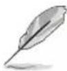
Refer to section 1.7.1 Front panel LEDs for the LED descriptions.

Turn off the system power and detach the power supply before removing or replacing any system component.
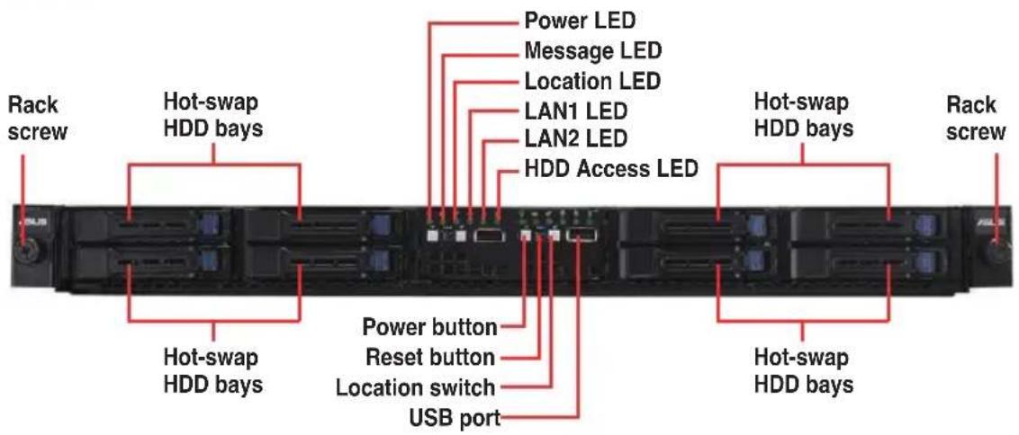
1.5 Rear panel features
The rear panel includes the expansion slots, system power sockets, and rear fans. The I/O shields with openings for the rear panel connectors on the motherboard are also placed in the real panel.

The ports for the USB, VGA, and Gigabit LANs do not appear on the rear panel if the motherboards are not present.
RS700D-E6/PS8, RS702D-E6/PS8
RS704D-E6/PS8
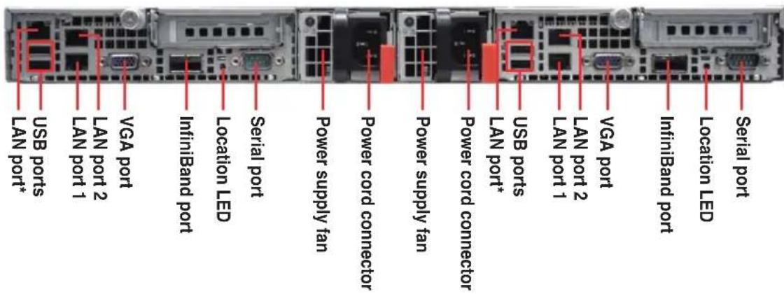

* These ports are for ASUS ASMB4-iKVM controller cards only.
** These ports allow connection with a QSFP cable to an InfiniBand switch.
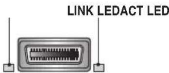
Infiniband (MQSFP1) indications
| Activity LED Link LED Description | ||
| Off Off No device | ||
| Orange Green Device plugged in; Ready | ||
| Orange Blinking | Green Device plugged in; Data transmitting | |
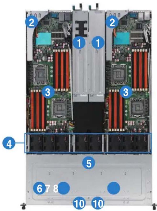
1.6 Internal features
The barebone server includes the basic components as shown.
RS700D-E6/PS4, RS702D-E6/PS4
- Power supplies and power fans
- PCI Express x16 slot Riser Cards (at x16 link)
- ASUS Z8NH-D12 server boards (RS700D-E6/PS4); ASUS Z8PH-D12/IFB server boards (RS702D-E6/PS4)
- System fans
- SATA/SAS backplane (hidden)
- Hot-swap HDD tray 1 and 3—Connect to SATA1 and SATA3 ports
- Hot-swap HDD tray 2 and 4—Connect to SATA2 and SATA4 ports
- Hot-swap HDD tray 1 and 3—Connect to SATA1 and SATA3 ports
- Hot-swap HDD tray 2 and 4—Connect to SATA2 and SATA4 ports
- Front I/O boards (hidden)

Turn off the system power and detach the power supply before removing or replacing any system component.
The barebone server does not include a floppy disk drive and an optical disc drive. Connect a USB floppy disk drive or a USB ODD to any of the USB ports on the front or rear panel if you need to use a floppy disk or a optical disc.
*WARNING
HAZARDOUS MOVING PARTS
KEEP FINGERS AND OTHER BODY PARTS AWAY
RS704D-E6/PS4
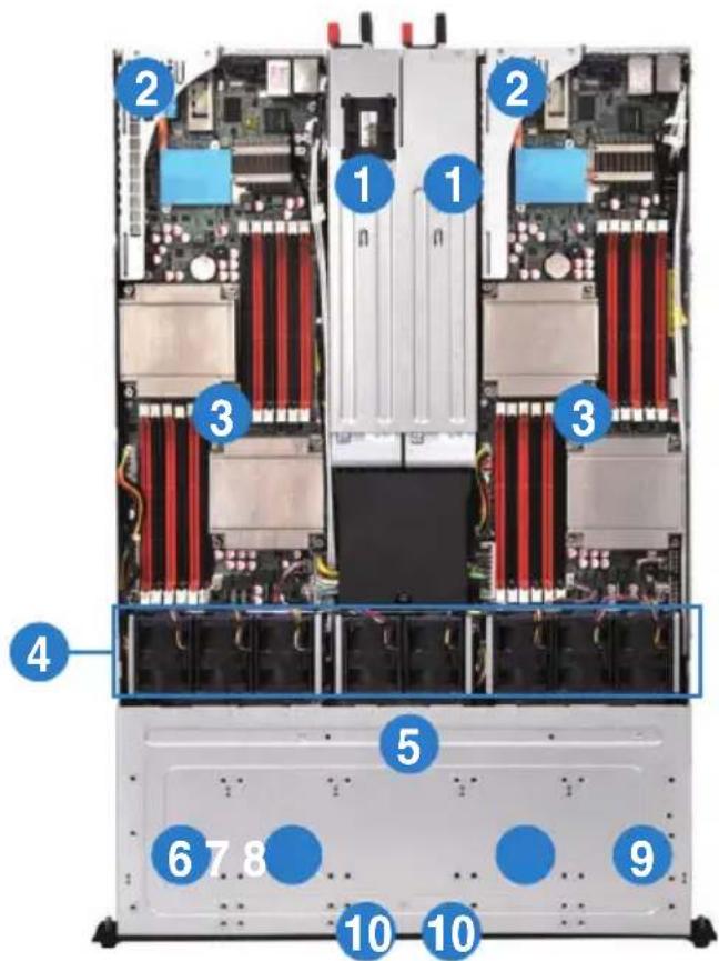
- Power supplies and power fans
- PCI Express x16 slot Riser Cards (at x16 link)
- ASUS Z8PH-D12 SE/QDR server boards
- System fans
- SATA/SAS backplane (hidden)
- HDD tray 1 and 3—Connect to SATA1 and SATA3 ports
- HDD tray 2 and 4—Connect to SATA2 and SATA4 ports
- HDD tray 1 and 3—Connect to SATA1 and SATA3 ports
- HDD tray 2 and 4—Connect to SATA2 and SATA4 ports
- Front I/O boards (hidden)

Turn off the system power and detach the power supply before removing or replacing any system component.
The barebone server does not include a floppy disk drive and an optical disc drive. Connect a USB floppy disk drive or a USB ODD to any of the USB ports on the front or rear panel if you need to use a floppy disk or a optical disc.
*WARNING
HAZARDOUS MOVING PARTS
KEEP FINGERS AND OTHER BODY PARTS AWAY
1.7 LED information
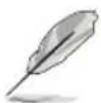
1.7.1 Front panel LEDs
| LED Icon | Display status | Description | |
| Power LED | [IMAGE] | ON System power ON | |
| HDD Access LED | [IMAGE] | OFFBlinking | No activityRead/write data into the HDD |
| Message LED | [IMAGE] | OFFBlinking | System is normal; no incoming eventASWM indicates a HW monitor event |
| Location LED | [IMAGE] | OFFON | Normal statusLocation switch is pressed(Press the location switch again to turn off) |
| LAN LEDs | [IMAGE] | OFFBlinkingON | No LAN connectionLAN is transmitting or receiving dataLAN connection is present |
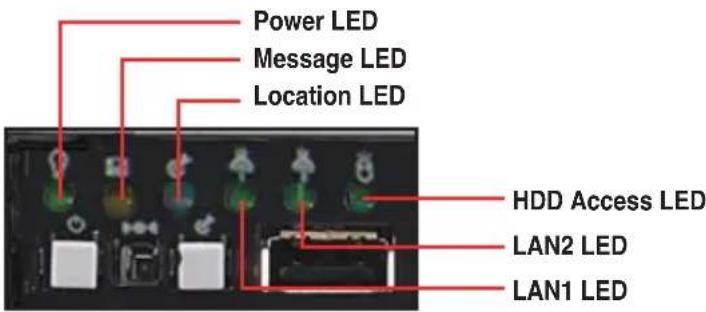
1.7.2 LAN (RJ-45) LEDs
ACT/LINK LED SPEED LED
Status Description Status Description
OFF No link OFF 10 Mbps connection
GREEN Linked ORANGE 100 Mbps connection
BLINKING Data activity GREEN 1 Gbps connection
1.7.3 HDD status LED
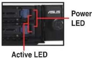
| HDD LED Status Define | ||
| LED Status | Description | |
| Power | Green Light ON | Power On (detection HDD present) |
| Red Light ON | RAID HDD fail (HDD plug-in ready but detection error) | |
| G/R Blinking RAID rebuilding | ||
| OFF HDD not found | ||
| Active | Green Blink | Data read/write to HDD |
Chapter 2
This chapter lists the hardware setup procedures that you have to perform when installing or removing system components.

natural_image
Front view of a server rack with multiple drive bays and indicator lights (no visible text or labels)ASUS RS700D-E6/PS8, RS702D-E6/PS8, RS704D-E6/PS8
Hardware setup
2.1 Chassis cover
Removing the rear cover
- Loosen the two thumbscrews on the rear panel to release the rear cover from the chassis.
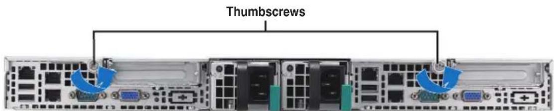
- Firmly hold the cover and slide it toward the rear panel for about half an inch until it is disengaged from the chassis.
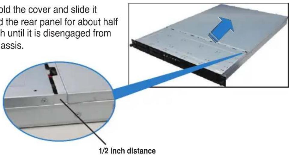
- Lift the cover from the chassis.
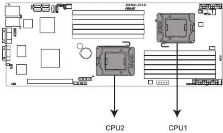
2.2 Central Processing Unit (CPU)
The motherboard comes with dual surface mount LGA 1366 Socket designed for the Intel ^ Xeon 5500 series CPU in the Land Grid Array (LGA) package.

- Upon purchase of the motherboard, ensure that the PnP cap is on the socket and the socket contacts are not bent. Contact your retailer immediately if the PnP cap is missing, or if you see any damage to the PnP cap/socket contacts/motherboard components. ASUS shoulders the repair cost only if the damage is shipment/transit-related.
- Keep the cap after installing the motherboard. ASUS will process Return Merchandise Authorization (RMA) requests only if the motherboard comes with the cap on the Socket 1366.
- The product warranty does not cover damage to the socket contacts resulting from incorrect CPU installation/removal, or misplacement/loss/incorrect removal of the PnP cap.
2.2.1 Installing the CPU
To install a CPU:
- Locate the CPU socket on the motherboard.
Z8NH-D12 CPU LGA1366 Socket
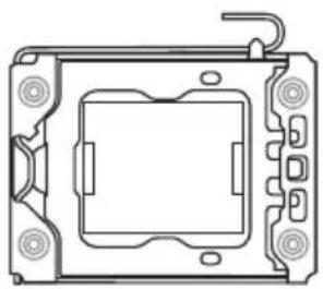
natural_image
Technical line drawing of a mechanical component with mounting holes and a central square housing (no text or symbols)
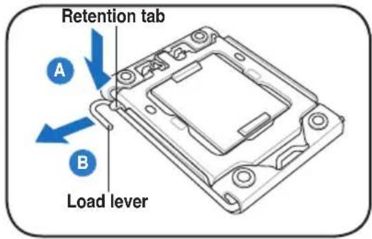
Before installing the CPU, ensure that the socket box is facing towards you and the load lever is on your left.
- Press the load lever with your thumb (A), then move it to the left (B) until it is released from the retention tab.

To prevent damage to the socket pins, do not remove the PnP cap unless you are installing a CPU.
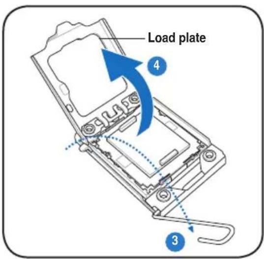
- Lift the load lever in the direction of the arrow to a 135^ angle.
- Lift the load plate with your thumb and forefinger to a 100^ angle.
- Remove the PnP cap from the CPU socket.
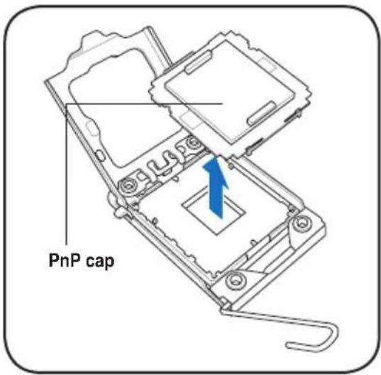
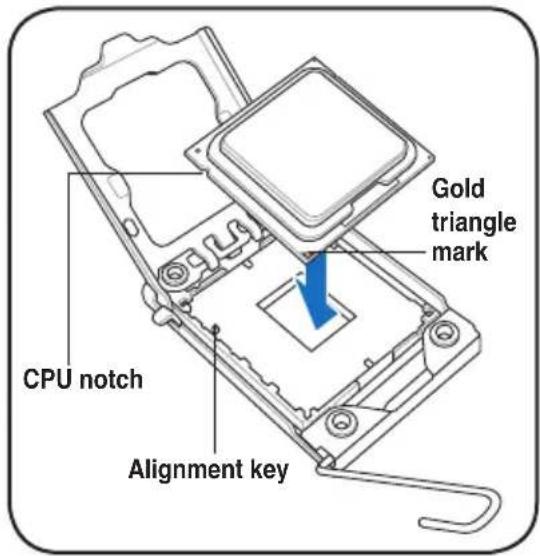
- Position the CPU over the socket, making sure that the gold triangle is on the bottom-left corner of the socket, and then fit the socket alignment key into the CPU notch.

The CPU fits in only one correct orientation. DO NOT force the CPU into the socket to prevent bending the connectors on the socket and damaging the CPU!
- Apply several drops of thermal paste to the exposed area of the CPU that the heatsink will be in contact with, ensuring that it is spread in an even thin layer.
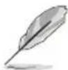
Some heatsinks come with pre-applied thermal paste. If so, skip this step.

The thermal paste is toxic and inedible. If it gets into your eyes or touches your skin, ensure to wash it off immediately and seek professional medical help.
natural_image
Line drawing of a mechanical assembly with a tool inserted, showing a component being inserted (no text or symbols present)
To prevent contaminating the paste, DO NOT spread the paste with your finger directly.
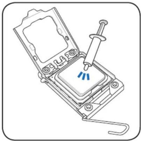
- Close the load plate (A), and then push the load lever (B) until it snaps into the retention tab.
2.2.2 Installing the CPU heatsink and airduct
To install the CPU heatsink:
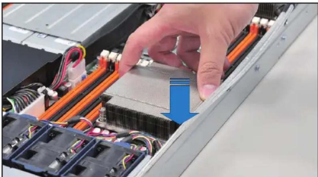
- Place the heatsink on top of the installed CPU, ensuring that the four fasteners match the holes on the motherboard.
natural_image
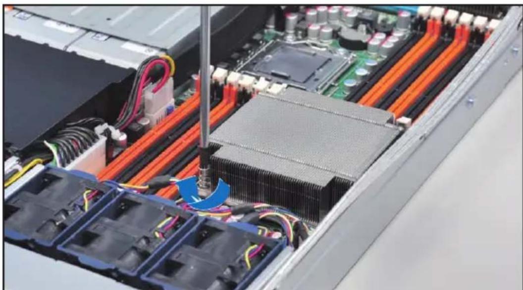
Close-up of a hand pressing down on an electronic device chassis with cooling fins and wiring (no visible text or symbols)- Twist each of the four screws with a Philips (cross) screwdriver just enough to attach the heatsink to the motherboard. When the four screws are attached, tighten them one by one to completely secure the heatsink.
natural_image
Interior view of an electronic device showing a CPU socket, thermal conductivity bands, and wiring (no visible text or symbols)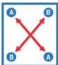
flowchart
graph TD
    A["A"] --> B["B"]
    B --> A
    A --> B
    B --> A
Tighten the four heatsink screws in a diagonal sequence.
2.3 System memory
2.3.1 Overview
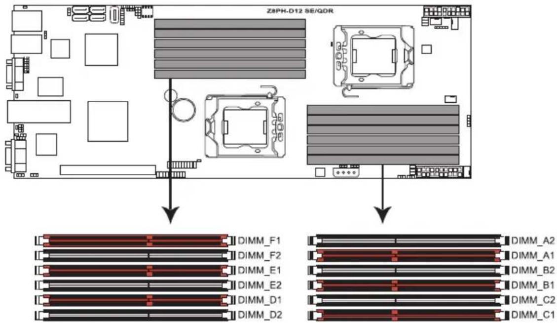
The motherboard comes with twelve (12) Double Data Rate 3 (DDR3) Dual Inline Memory Modules (DIMM) sockets.
The figure illustrates the location of the DDR3 DIMM sockets:
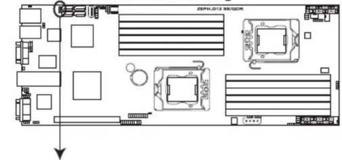
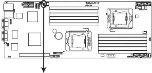
Z8NH-D12 240-pin DDR3 DIMM sockets
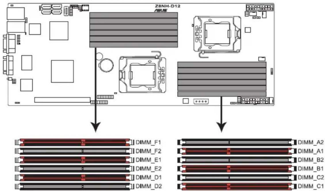
Z8PH-D12 SE/QDR 240-pin DDR3 DIMM sockets
2.3.2 Memory Configurations
You may install 1 GB, 2 GB, 4 GB, or 8GB registered / unbuffered ECC DDR3 DIMMs into the DIMM sockets using the memory configurations in this section.

• Always install DIMMs with the same CAS latency. For optimum compatibility, we recommend that you obtain memory modules from the same vendor. Refer to the Qualified Vendors List on the ASUS web site.
- You may install varying memory sizes in Channel A, Channel B and Channel C. The system maps the total size of the lower-sized channel for the dual-channel or triple-channel configuration. Any excess memory from the higher-sized channel is then mapped for single-channel operation.
- Due to the memory address limitation on 32-bit Windows OS, when you install 4GB or more memory on the motherboard, the actual usable memory for the OS can be about 3GB or less. For effective use of memory, we recommend that you do any of the following:
- Use a maximum of 3GB system memory if you are using a 32-bit Windows OS.
- Install a 64-bit Windows OS when you want to install 4GB or more on the motherboard.
For more details, refer to the Microsoft® support site at http://support.microsoft.com/kb/929605/en-us.
- This motherboard does not support DIMMs made up of 256 Mb (32MB) chips or less (Memory chip capacity counts in Megabit, 8 Megabit/Mb = 1 Megabyte/MB).
Memory population table
| CPU 1 Configuration | |||||||
| DIMM_A2 | DIMM_A1 | DIMM_B2 | DIMM | B1 | DIMM_C2 | DIMM_C1 | |
| 1 DIMMs | --- --- | --- | ● | ||||
| 2 DIMMs | --- --- | ● | ● | ||||
| 3 DIMMs | --- --- | ● | ● | ● | |||
| 4 DIMMs | ● | ● | --- | ● | ● | ||
| 6 DIMMs | ● | ● | ● | ● | ● | ● | |
| CPU 2 Configuration | |||||||
| DIMM_D2 | DIMM_D1 | DIMM_E2 | DIMM | E1 | DIMM_F2 | DIMM_F1 | |
| 1 DIMMs | --- --- | --- | ● | ||||
| 2 DIMMs | --- --- | ● | ● | ||||
| 3 DIMMs | --- --- | ● | ● | ● | |||
| 4 DIMMs | ● | ● | --- | ● | ● | ||
| 6 DIMMs | ● | ● | ● | ● | ● | ● | |
2.3.3 Installing a DIMM

Ensure to unplug the power supply before adding or removing DIMMs or other system components. Failure to do so may cause severe damage to both the motherboard and the components.
- Unlock a DIMM socket by pressing the retaining clips outward.
- Align a DIMM on the socket such that the notch on the DIMM matches the break on the socket.
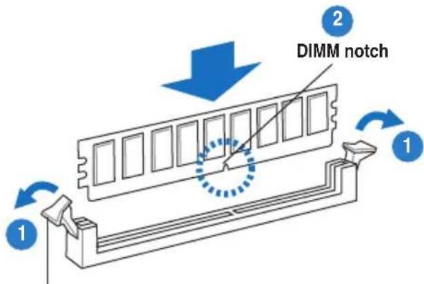
Unlocked retaining clip

A DIMM is keyed with a notch so that it fits in only one direction. DO NOT force a DIMM into a socket to avoid damaging the DIMM.
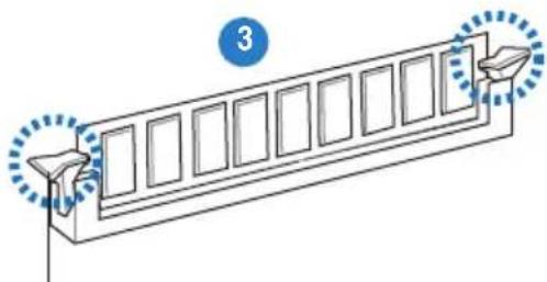
- Firmly insert the DIMM into the socket until the retaining clips snap back in place and the DIMM is properly seated.
natural_image
Diagram of a mechanical component with numbered parts and directional arrows, no text or symbols presentLocked Retaining Clip
2.3.4 Removing a DIMM
Follow these steps to remove a DIMM.
- Simultaneously press the retaining clips outward to unlock the DIMM.
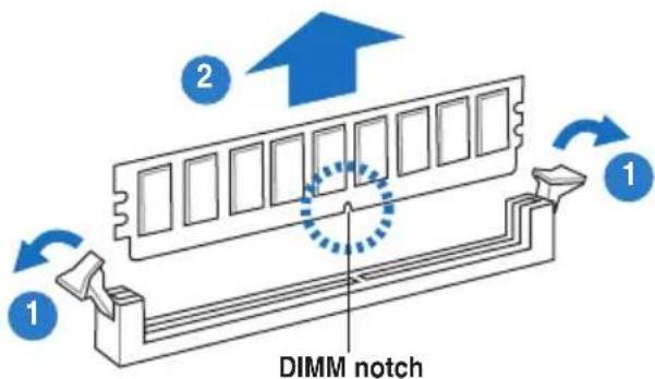
Support the DIMM lightly with your fingers when pressing the retaining clips. The DIMM might get damaged when it flips out with extra force.
- Remove the DIMM from the socket.
2.4 Hard disk drives
The system supports four hot-swap SATAII/SAS hard disk drives. The hard disk drive installed on the drive tray connects to the motherboard SATAII/SAS ports via the SATAII/SAS backplane. Follow the illustration below for HDD installation.
To install a hot-swap SATAII/SAS HDD
- Release a drive tray by pushing the spring lock to the right, and then pulling the tray lever outward. The drive tray ejects slightly after you pull out the lever.
- Firmly hold the tray lever and pull the drive tray out of the bay.
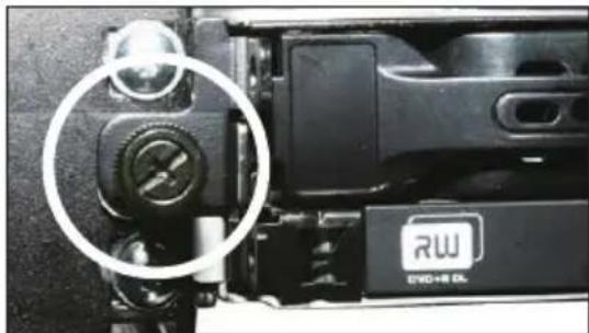
- Remove the drive tray supporting pillar shown in the right figure.
Supporting pillar
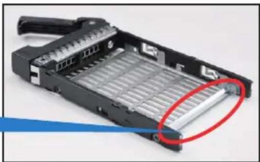
natural_image
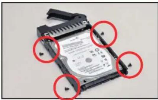
Close-up of a black hard disk drive housing with a red circular highlight on its side (no text or symbols visible)- Place a SATAII/SAS hard disk drive on the tray, and then secure it with four screws.
natural_image
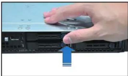
Close-up of a hard disk drive head with four red-circled mounting points (no visible text or symbols)- Carefully insert the drive tray and push it all the way to the depth of the bay until just a small fraction of the tray edge protrudes.

When installed, the SATAII/SAS connector on the drive connects to the SATAII/SAS interface on the backplane.
- Push the tray lever until it clicks, and secures the drive tray in place. The drive tray is correctly placed when its front edge aligns with the bay edge.
- Repeat steps 1 to 5 if you wish to install a second SATAII/SAS drive.
natural_image
Hand pressing a button on a computer monitor (no visible text or symbols)2.5 Expansion slot
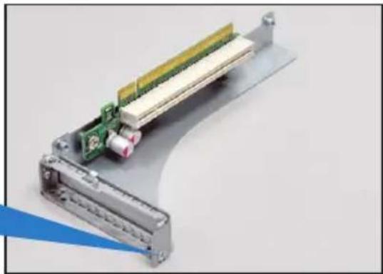
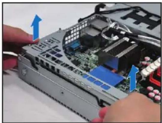
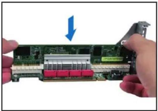
2.5.1 Installing an expansion card to the riser card bracket
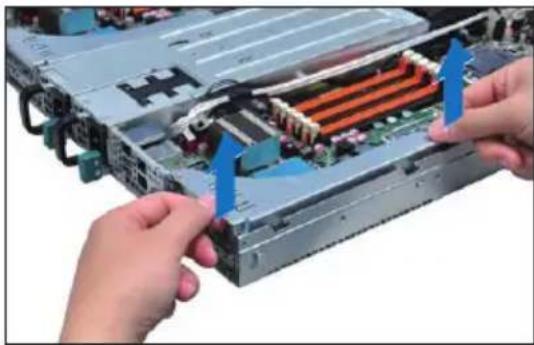
The barebone server comes with a riser card bracket. You need to remove the bracket if you want to install PCI Express x16 expansion cards.
To install a PCI Express x16 card
- Firmly hold the riser card bracket, and then pull it up to detach it from the PCI Express x16 slot on the motherboard.
natural_image
Close-up of hands installing a computer motherboard with blue arrows indicating component alignment (no text or symbols visible)- Place the riser card bracket on a flat and stable surface, and then remove the screw from the slot bay.
natural_image
3D rendering of a mechanical assembly with green and yellow components mounted on a metal frame (no visible text or symbols)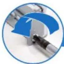
natural_image
Close-up of a blue and silver curved object with a black handle, enclosed in a circular frame (no text or symbols visible)- Install a PCI Express x16 card to the bracket as shown, and then secure the card with a screw.
natural_image
Close-up of hands holding a green printed circuit board with a blue arrow pointing to it, no visible text or symbols.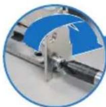
natural_image
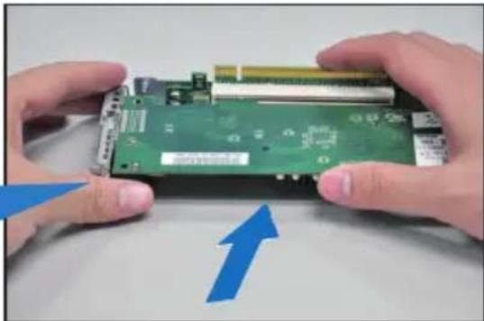
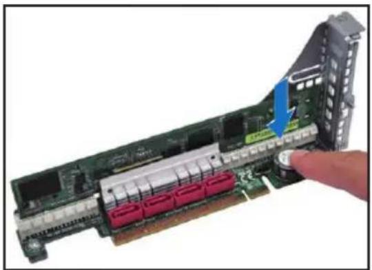
Close-up of a mechanical component with blue and silver parts, no visible text or symbols- Press the riser card bracket until the golden connectors completely fit the slot and the bracket aligns with the rear panel.
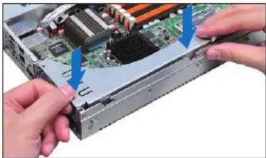
natural_image
Close-up of hands installing a computer motherboard with blue arrows indicating component alignment (no text or symbols visible)- Connect the cable(s) to the card, if applicable.
2.5.2 Configuring an expansion card
After installing the expansion card, configure the it by adjusting the software settings.
- Turn on the system and change the necessary BIOS settings, if any. See Chapter 5 for information on BIOS setup.
- Assign an IRQ to the card. Refer to the following tables.
- Install the software drivers for the expansion card.
Standard Interrupt assignments
| IRQ Priority Standard function | ||
| 0 1 System Timer | ||
| 1 2 Keyboard Controller | ||
| 2 - Programmable Interrupt | ||
| 4* 12 Communications Port (COM1) | ||
| 5* 13 -- | ||
| 6 14 Floppy Disk Controller | ||
| 7* 15 -- | ||
| 8 3 System CMOS/Real Time Clock | ||
| 9* 4 ACPI Mode when used | ||
| 10* 5 IRQ Holder for PCI Steering | ||
| 11* 6 IRQ Holder for PCI Steering | ||
| 12* 7 PS/2 Compatible Mouse Port | ||
| 13 8 Numeric Data Processor | ||
| 14* 9 Primary IDE Channel | ||
| 15* 10 Secondary IDE Channel | ||
* These IRQs are usually available for ISA or PCI devices.
2.6 Cable connections

- The bundled system cables are pre-connected before shipment. You do not need to disconnect these cables unless you will remove pre-installed components to install additional devices.
• Refer to Chapter 4 for detailed information on the connectors.
Pre-connected system cables
- 20-pin proprietary power connector (from power supply to motherboard)
- 4-pin proprietary power connector (from power supply to motherboard)
- System fan connectors (from motherboard FRNT_FAN1, FRNT_FAN2, FRNT_FAN3 and FRNT_FAN4 to system fans)
- USB connector (from motherboard to front I/O board)
- Panel connector (from motherboard to front I/O board)
- SATA connectors (from motherboard to SATAII/SAS backplane board)
- Auxiliary panel connector (from motherboard to front I/O board)
2.7 Removable/optional components
You may need to remove previously installed system components when installing or removing system devices. Or you may need to install the optional components into the system. This section tells how to remove/install the following components:
- System fans
- Power supply units
- ASUS ASMB4-iKVM (optional)
4 ASUS PIKE Riser card (optional)

Ensure that the system is turned off before removing any components.
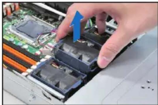
2.7.1 Replacing system fans
To uninstall the system fans:
- Disconnect the system fan cable from the fan connector on the motherboard.
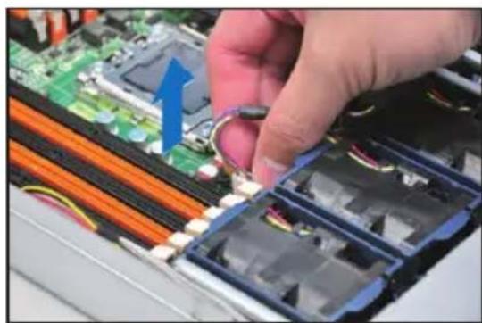
natural_image
Close-up of hands installing a battery pack on an electronic circuit board (no visible text or symbols)-
Lift the fan, and then set aside.
-
Repeat step 1 to 2 to uninstall the other system fans.
natural_image
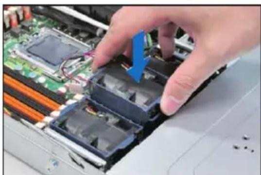
Close-up of a hand inserting electronic components into a computer motherboard (no visible text or symbols)To reinstall the system fans
-
Insert the fan to the fan cage. The airflow directional arrow on the fan side should point towards the system rear panel.
-
Connect the system fan cable to the fan connector on the motherboard.
natural_image
Close-up of hands installing or adjusting a computer motherboard with plastic components (no visible text or symbols)- Recover the rear cover. Press down gently on the location above the system fans to ensure proper fan installation, as shown in the right figure.

natural_image
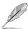
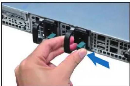
Close-up of hands operating a computer monitor with a blue arrow indicating the screen (no visible text or symbols)2.7.2 Replacing power supply units
Follow the steps below to replace the failed power supply unit (PSU).
To replace the failed PSU
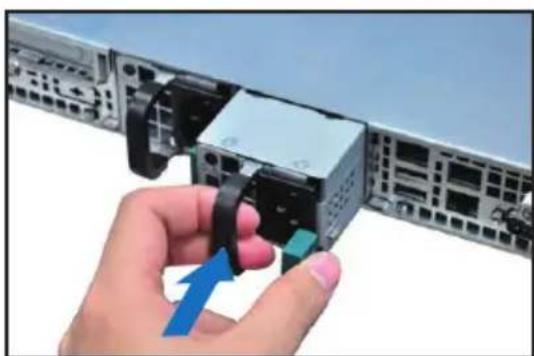
- Hold the PSU lever and press the PSU latch.
natural_image
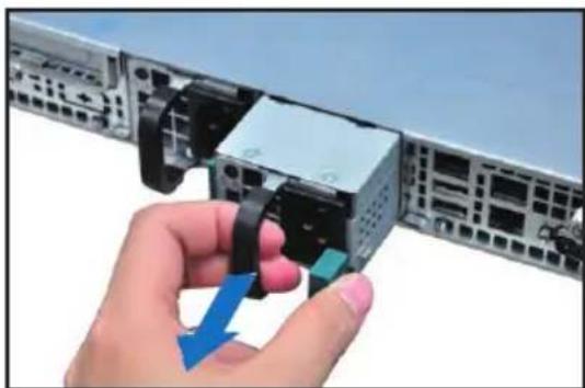
Hand inserting a component into a server rack, showing blue arrows indicating direction (no text or symbols)- Firmly pull the failed PSU out of the server chassis.
natural_image
Hand inserting a USB into a server rack component, showing blue and green arrows (no text or symbols)- Firmly push the new PSU into the chassis until the latch locks to the server chassis.
natural_image
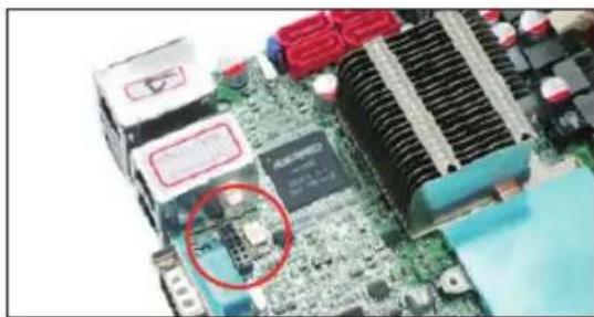
Hand inserting a USB into a server rack component (no text or symbols visible)2.7.3 Installing ASMB4 series management board (optional)
Follow the steps below to install an optional ASMB4 series management board on your motherboard.
- Locate the BMC_FW1 header on the motherboard.
natural_image
Close-up of a computer motherboard with visible CPU socket, cooling fans, and heatsink (no text or symbols)- Orient and press the ASMB4 management card in place.
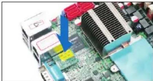
natural_image
Close-up of a computer motherboard with visible CPU socket, heatsink, and heat sink (no text or symbols)- Insert the LAN cable plug to the LAN3 port for server management.
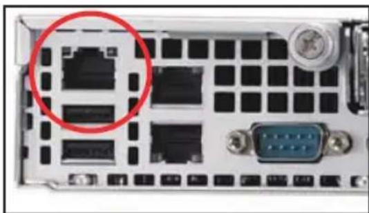
natural_image
Front view of a server rack with ports, connectors, and a blue VGA (no visible text or labels)2.7.4 Installing ASUS PIKE Riser Card (optional)
Follow the steps below to install the optional ASUS PIKE SAS RAID card to the ASUS PIKE riser card.
- Firmly hold the riser card bracket, then pull it up to detach it from the PCI Express x16 slot on the motherboard.
natural_image
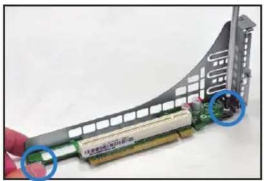
Close-up of hands installing a computer motherboard with blue arrows indicating component placement (no text or symbols visible)- Locate the two screws on the riser card bracket, then remove the screws from the bracket.
natural_image
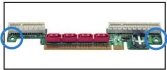
Close-up of a computer motherboard with a CPU socket and cable, showing a hand holding the component (no visible text or symbols)- Locate the two screw holes on the PIKE riser card.
natural_image
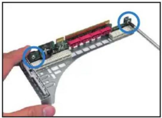
Close-up of a computer RAM module with red connectors and green connectors, showing internal structure (no text or symbols visible)- Secure the PIKE riser card to the riser card bracket with two screws.
natural_image
Close-up of a computer motherboard with a hand holding the cable, showing internal components and a blue circle highlighting a component (no text or symbols visible)- Align and insert the golden fingers of the PIKE SAS RAID card into the card slot on the PIKE raiser card. Ensure the card is completely seated on the slot.
natural_image
Close-up of hands holding a green computer motherboard with a blue arrow pointing to a component (no visible text or symbols)- For PIKE 1078 SAS RAID card, snap the i Button into the i Button slot on the PIKE raiser card.
natural_image
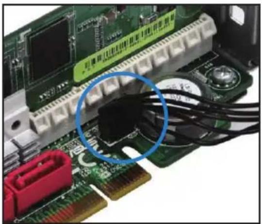
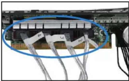
Close-up of a computer RAM module with red connectors and a blue arrow indicating a component (no visible text or symbols)- Connect the SGPIO cable (pre-installed to the barebone server) to the SGPIO connector on the PIKE Riser card.
natural_image
Close-up of a green circuit board with attached components and a blue circle highlighting a component (no visible text or symbols)- Remove the SATA/SAS cables from the onboard SATA1-4 connectors.
natural_image
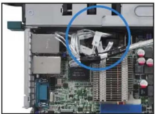
Close-up of an internal computer motherboard with visible CPU socket and cable routing (no text or symbols)- Connect the SATA/SAS cables to the SAS1-4 connectors on the PIKE riser card.
natural_image
Close-up of electronic circuit board with bundled cables and connectors (no visible text or symbols)-
Align the riser card bracket to the PCI Express x16 slot on the motherboard.
-
Press the riser card bracket until the golden fingers completely fit the slot and the bracket aligns with the rear panel.
natural_image
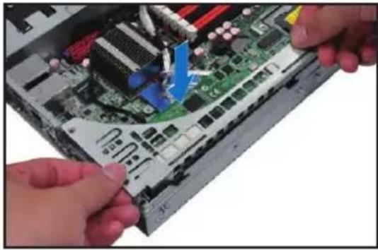
Close-up of hands installing a computer motherboard with visible CPU socket and motherboard (no text or symbols)- Temporarily remove the two system fans in front of the center mylar.
natural_image
Close-up of hands installing or adjusting a computer motherboard with visible wiring and components (no text or symbols)-
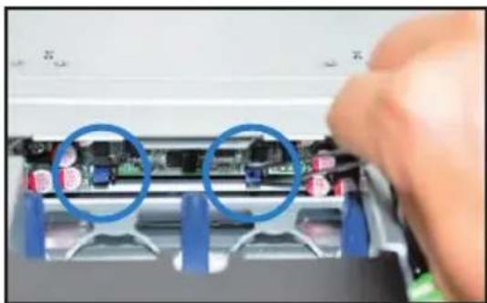
Move the SGPSEL1 jumper on the SATA/SAS backplane to 2–3. If you install two PIKE riser cards in the chassis, move both the jumpers.
-
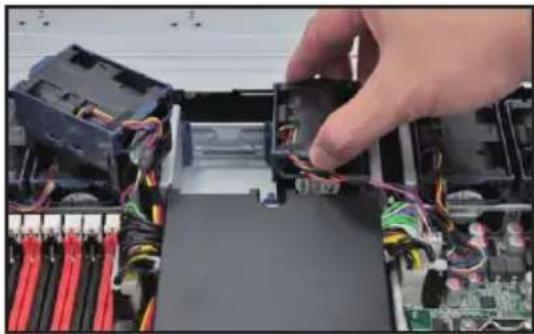
Place the two system fans back to their default positions.
natural_image
Close-up of a hand inserting into a computer motherboard with blue circular annotations highlighting internal components (no text or symbols visible)Chapter 3
This chapter describes how to install the optional components and devices into the barebone server.

natural_image
Front view of a server rack with multiple drive bays and indicator lights (no visible text or labels)installation options
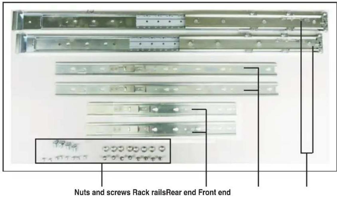
3.1 Rackmount rail kit items (optional)
Your rackmount rail kit package contains:
- two pair of server rails (for the server)
- two pairs of rack rails (for the rack)
- Nut-and-bolt type screws
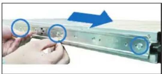
3.2 Attaching the rails to the server
To attach the server rails
- Attach the front end of the server rail to the side of the chassis, matching each of the three hooks to the holes on the rail. Then slide the rail toward the front panel until it locks in place.
natural_image
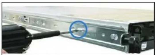
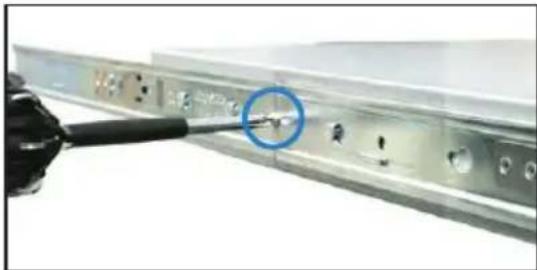
Close-up of hands holding a metal electronic device with three circular annotations pointing to the ports (no text or symbols visible)- Attach the rear end of the server rail to the side of the chassis with one screw.
natural_image
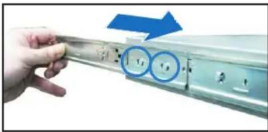
Close-up of a computer monitor with a blue circular annotation highlighting a cable (no visible text or symbols)- Attach the rear end of the server rail to the side of the chassis, matching each of the two hooks to the holes on the rail, and then slide the rail toward the front panel until it locks in place.
natural_image
Hand holding a metallic mechanical component with two blue circular annotations highlighting features (no text or symbols present)- Secure the rear end of the server rail to the side of the chassis with one screw.
natural_image
Close-up of a metallic electronic device with a black cable inserted, showing internal components and a blue circle highlighting a feature (no text or symbols visible)- Repeat step 1 to 4 to attach the second server rail to the other side of the chassis.
3.3 Attaching the rack rails
To attach the rack rails
- Select one unit of space (1U) on the rack where you want to install the barebone server.
- Install the nuts on the holes of the 1U space on the rack front.
- Install the nuts on the holes of the 1U space on the corresponding rack rear.
- Measure the depth of the rack to determine the length of the rack rails.
- Measure the rack rail when assembled to ensure that it fits the rack.
-
Position the rack rail to the 1U space on the rack. Ensure that the front end of the rack rail goes to the front of the rack space.
-
Secure the front end of the rail with two rack screws.
-
Secure the rear end of the rail with two rack screws.
-
Repeat steps 5 to 8 to assemble and attach the second rack rail.
natural_image
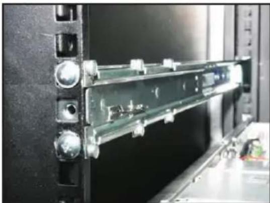
Close-up of a mechanical assembly with green components mounted on a black base (no visible text or symbols)3.4 Rackmounting the server
To mount the server to the rack
-
Align the server rails with the rack rails, then push the server all the way to the depth of the rack.
-
Tighten the two rack screws to secure the server in place.
natural_image
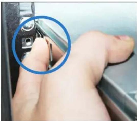
Close-up of a camera lens and camera body with a circular annotation highlighting the lens (no readable text or symbols)To uninstall the server from the rack
-
Loosen the rack screws that secured the server to the rack.
-
Pull the server from the rack.

Remember to press the latches on both sides to release the server from the rack.
natural_image
Close-up of a hand holding a small mechanical component, with a blue circle highlighting the part (no text or symbols visible)Chapter 4
This chapter includes the motherboard layout and brief descriptions of the jumpers and internal connectors.

natural_image
Front view of a server rack with multiple drive bays and indicator lights (no visible text or labels)Mothetherd Info
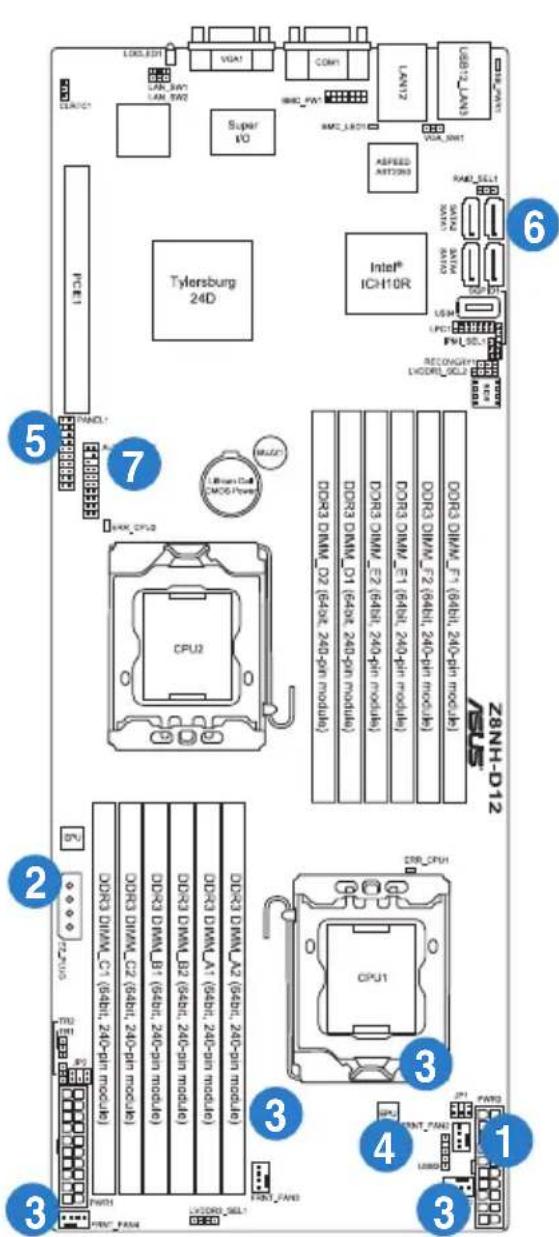
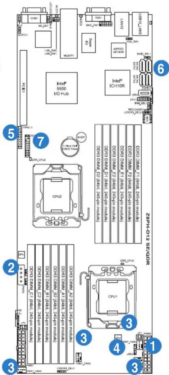
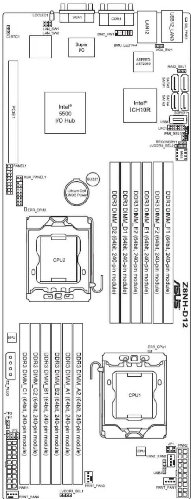
4.1 Motherboard layout
Z8NH-D12 (For RS700D-E6/PS8)
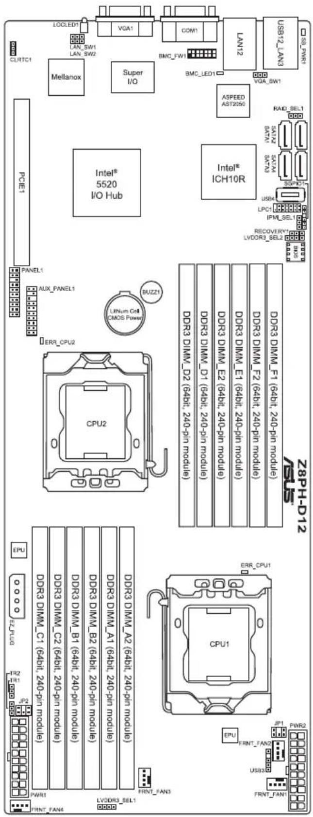
Z8PH-D12/IFB (For RS702D-E6/PS8)
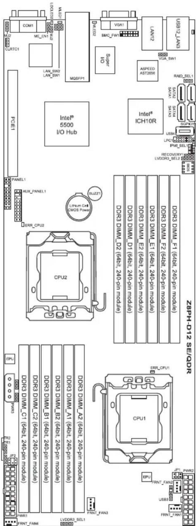
Z8PH-D12 SE/QDR (For RS704D-E6/PS8)
Layout contents
Jumpers Page
| 1. Clear RTC RAM (CLRTC1) 4-6 |
| 2. VGA controller setting (3-pin VGA_SW1) 4-7 |
| 3. DDR3 voltage control setting (4-pin LVDDR3_SEL1, LVDDR3_SEL2) 4-8 |
| 4. LAN controller setting (3-pin LAN_SW1, LAN_SW2) 4-9 |
| 5. Intel ICH10R® SATA ports S/W RAID setting (3-pin RAID_SEL1) 4-10 |
| 6. Force BIOS recovery setting (3-pin RECOVERY1) 4-11 |
Internal connectors Page
| 1. Serial ATA connectors (7-pin SATA1, SATA2, SATA 3, SATA4) 4-12 | |
| 2. USB connector (5-1 pin USB3; A-Type USB4) 4-13 | |
| 3. Front fan connectors (4-pin FRNT_FAN1, FRNT_FAN2, FRNT_FAN3, FRNT_FAN4) | 4-14 |
| 4. LPC debug card connector (14-1 pin LPC1) 4-15 | |
| 5. Serial General Purpose Input/Output connector (6-1 pin SGPIO1) 4-15 | |
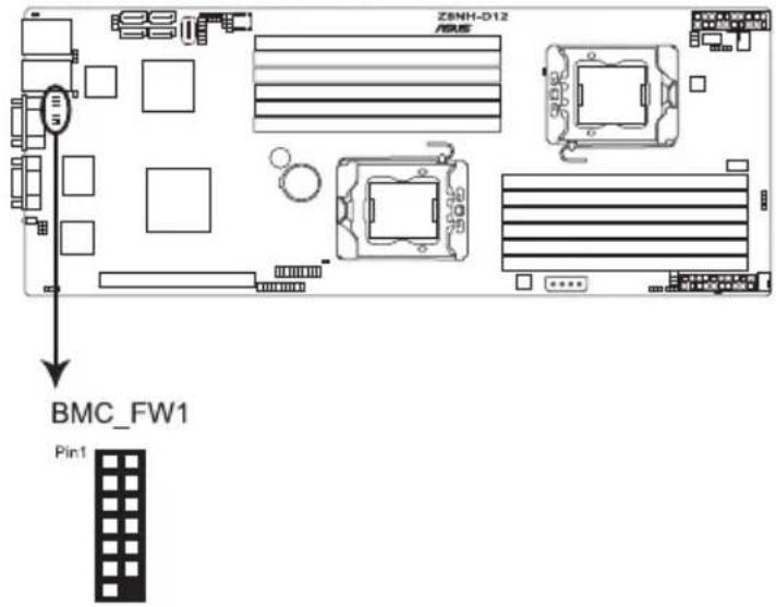
| 6. BMC header (BMC_FW1) | 4-16 |
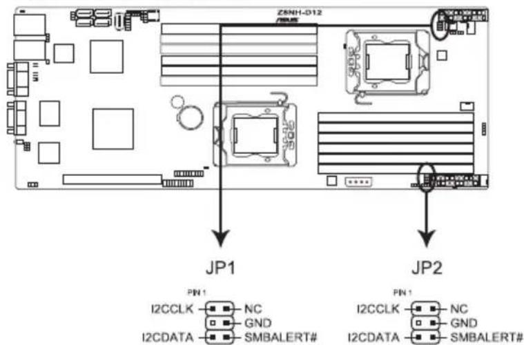
| 7. Power Supply SMBus connectors (6-1 pin JP1, JP2) | 4-16 |
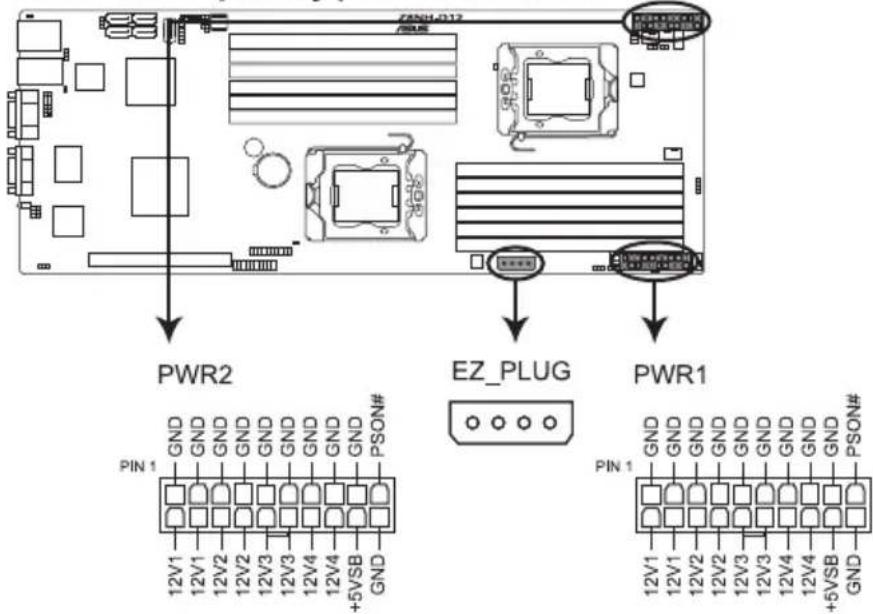
| 8. Proprietary power connectors (20-pin PWR1, 20-pin PWR2, 4-pin PWR3) | 4-17 |
| 9. System panel connector (20-pin PANEL1) | 4-18 |
| 10. Auxiliary panel connector (20-pin AUX_PANEL1) | 4-19 |
Internal LEDs Page
| 1. Standby power LED | 4-20 |
| 2. CPU warning LED (ERR_CPU1, ERR_CPU2) | 4-20 |
4.2 Jumpers
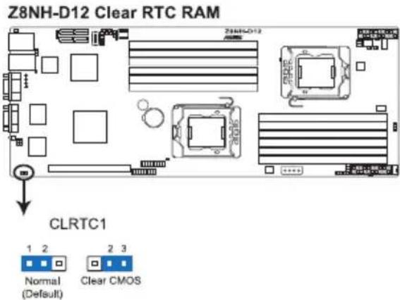
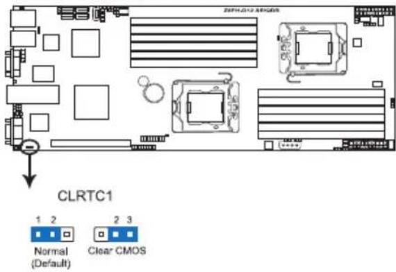
1. Clear RTC RAM (CLRTC1)
This jumper allows you to clear the Real Time Clock (RTC) RAM in CMOS. You can clear the CMOS memory of date, time, and system setup parameters by erasing the CMOS RTC RAM data. The onboard button cell battery powers the RAM data in CMOS, which include system setup information such as system passwords.
To erase the RTC RAM:
- Turn OFF the computer and unplug the power cord.
- Move the jumper cap from pins 1–2 (default) to pins 2–3. Keep the cap on pins 2–3 for about 5–10 seconds, then move the cap back to pins 1–2.
- Plug the power cord and turn ON the computer.
- Hold down the
key during the boot process and enter BIOS setup to re-enter data.

Except when clearing the RTC RAM, never remove the cap on CLRTC jumper default position. Removing the cap will cause system boot failure!

If the steps above do not help, remove the onboard battery and move the jumper again to clear the CMOS RTC RAM data. After the CMOS clearance, reinstall the battery.
Z8PH-D12 SE/QDR Clear RTC RAM
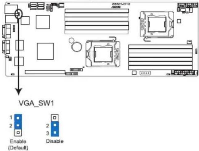
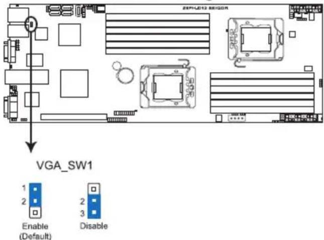
2. VGA controller setting (3-pin VGA\_SW1)
This jumper allows you to enable or disable the onboard VGA controller. Set to pins 1–2 to activate the VGA feature.
Z8NH-D12 VGA setting
Z8PH-D12 SE/QDR VGA setting
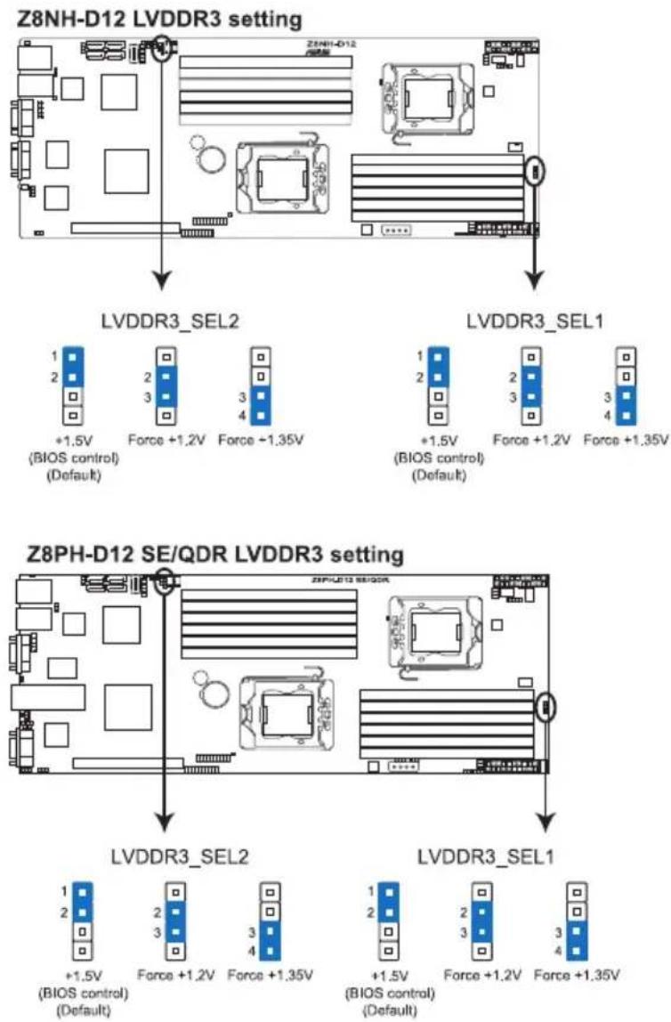
3. DDR3 voltage control setting (4-pin LVDDR3\_SEL1; LVDDR3\_SEL2)
These jumpers allow you to adjust the DIMM voltage. Set to pins 1–2 to select 1.5V BIOS control, pins 2–3 to select 1.2V Force or 3–4 to select 1.35V Force.
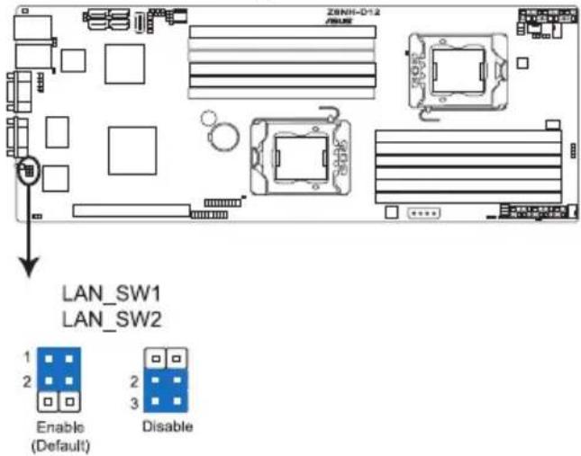
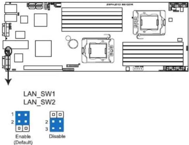
4. LAN controller setting (3-pin LAN\_SW1, LAN\_SW2)
These jumpers allow you to enable or disable the onboard Intel ^® Intel 82574LGigabit LAN controllers. Set to pins 1–2 to activate the Gigabit LAN feature.
Z8NH-D12 LAN setting
Z8PH-D12 SE/QDR LAN setting
5. Intel ^ ICH10R SATA port S/W RAID setting (3-pin RAID\_SEL1)
This jumper allows you to select the Serial ATA RAID configuration utility to use when you create disk arrays. Place the jumper caps on pins 1–2 if you want to use the LSI Logic Embedded SATA RAID Setup Utility (default); otherwise, place the jumper caps on pins 2–3 to use the Intel ^® Matrix Storage Manager (IMSM).
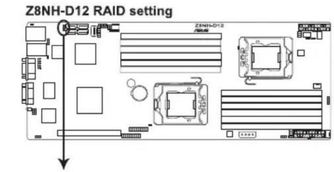
RAID_SEL1
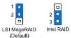
Z8PH-D12 SE/QDR RAID setting
RAID_SEL1

6. Force BIOS recovery setting (3-pin RECOVERY1)
This jumper allows you to quickly update or recover the BIOS settings when it becomes corrupted.
To update the BIOS:
- Prepare a USB flash disk that contains the original or latest BIOS for the motherboard (XXXXXX.ROM) and the AFUDOS.EXE utility.
- Set the jumper to pins 2–3.
- Insert the USB flash and turn on the system to update the BIOS.
- Shut down the system.
- Set the jumper back to pins 1–2.
- Turn on the system.
Z8NH-D12 BIOS recovery setting
RECOVERY1

Normal (Default)

BIOS Recovery
Z8NH-D12 BIOS recovery setting
RECOVERY1

Normal (Default)

BIOS Recovery
4.3 Internal connectors
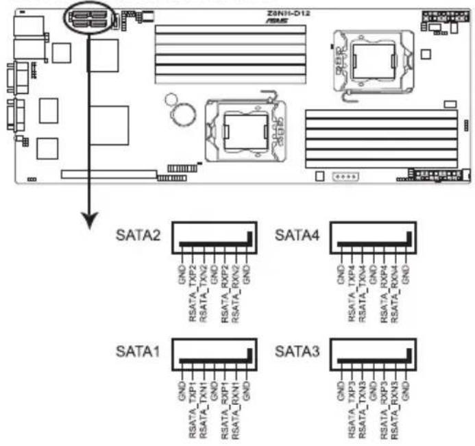
1. Serial ATA connectors (7-pin SATA1, SATA2, SATA3, SATA4)
Supported by the Intel ^® ICH10R chipset, these connectors are for the Serial ATA signal cables for Serial ATA hard disk drives that allows up to 3Gb/s of data transfer rate.
If you installed Serial ATA hard disk drives, you can create a RAID 0, RAID 1, RAID 10, or RAID 5 configuration.
Z8NH-D12 SATA connectors

The actual data transfer rate depends on the speed of Serial ATA hard disks installed.
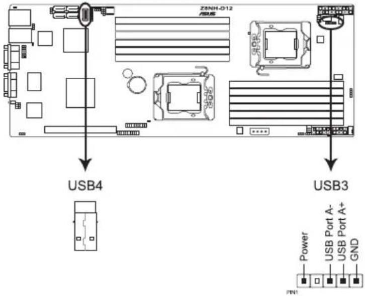
2. USB connector (5-1 pin USB3; A-Type USB4)
These connectors are for USB 2.0 ports. Connect the USB module cables to connectors USB3, then install the modules to a slot opening at the back of the system chassis. These USB connectors comply with USB 2.0 specification that supports up to 480 Mbps connection speed.
Z8NH-D12 USB 2.0 connectors
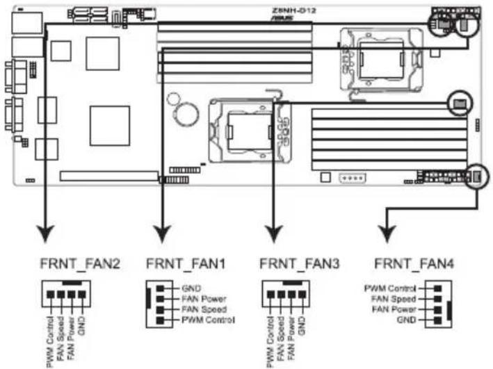
(4-pin FRNT_FAN1, FRNT_FAN2, FRNT_FAN3, FRNT_FAN4)
The fan connectors support cooling fans of 350 mA–740 mA (8.88 W max.) or a total of 3.15 A–6.66 A (53.28 W max.) at +12V. Connect the fan cables to the fan connectors on the motherboard, ensuring that the black wire of each cable matches the ground pin of the connector.

- DO NOT forget to connect the fan cables to the fan connectors. Insufficient air flow inside the system may damage the motherboard components.
• These are not jumpers! DO NOT place jumper caps on the fan connectors!
• All fans feature the ASUS Smart Fan technology.
Z8NH-D12 FAN connectors
flowchart
graph TD
    A["FRNT_FAN2"] --> B["PWM Control"]
    A --> C["FAN Speed"]
    A --> D["FAN Power"]
    A --> E["GND"]
    F["FRNT_FAN1"] --> G["GND"]
    F --> H["FAN Power"]
    F --> I["FAN Speed"]
    F --> J["GND"]
    K["FRNT_FAN3"] --> L["PWM Control"]
    K --> M["FAN Speed"]
    K --> N["FAN Power"]
    K --> O["GND"]
    P["FRNT_FAN4"] --> Q["PWM Control"]
    P --> R["FAN Speed"]
    P --> S["FAN Power"]
    P --> T["GND"]
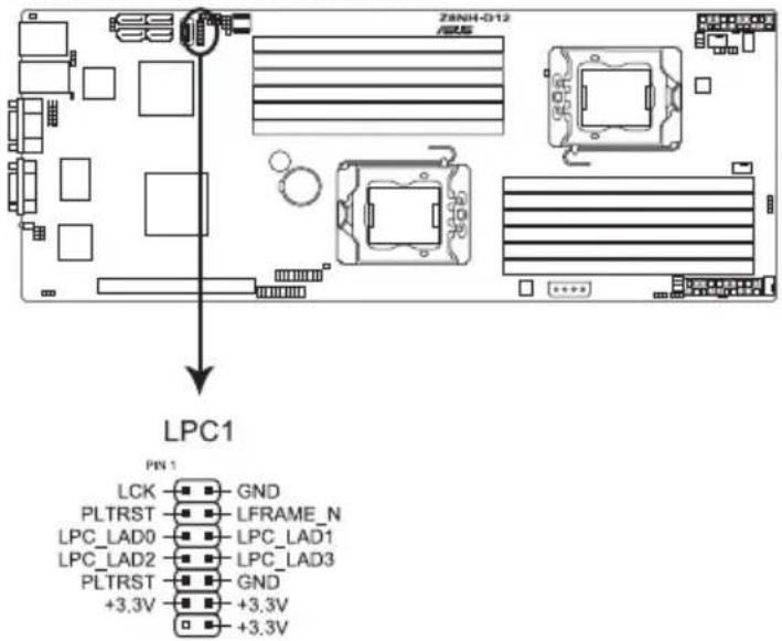
4. LPC debug card connector (14-1 pin LPC1)
This is a low pin count interface used to plug in the LPC debug card.
Z8NH-D12 LPC connector
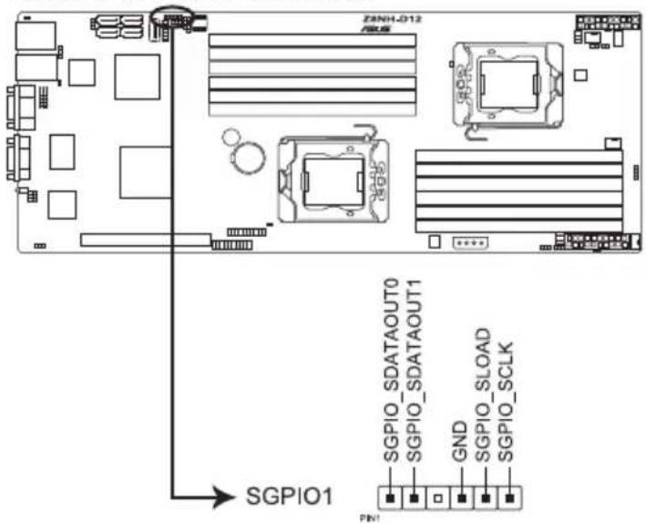
5. Serial General Purpose Input/Output connector (6-1 pin SGPIO1)
This connector is used for the SGPIO peripherals for the LSI MegaRAID and Intel Matrix RAID SATA LED.
Z8NH-D12 SGPIO connector
6. BMC header (BMC\_FW1)
The BMC connector on the motherboard supports an ASUS ^ Server Management Board 4 Series (ASMB4).
Z8NH-D12 BMC connector
7. Power Supply SMBus connectors (6-1 pin JP1, JP2)
These connectors allow you to connect SMBus (System Management Bus) to the power supply unit to read PSU information. Devices communicate with an SMBus host and/or other SMBus devices using the SMBus interface.
Z8NH-D12 JP connector
8. Proprietary power connectors
(20-pin PWR1, 20-pin PWR2, 4-pin PWR3)
These connectors are for Proprietary power supply plugs. The power supply plugs are designed to fit these connectors in only one orientation. Orient the connectors and push down firmly until they completely fit.
The 4-pin EZ_PLUG is designed for hard disk drives power supply. DO NOT connect other 4-pin power connectors of the power supply unit (PSU) to this connector.

- Connect either one of the 20-pin power connectors to boot up the system.
- Use of a PSU with a higher power output is recommended when configuring a system with more power-consuming devices. The system may become unstable or may not boot up if the power is inadequate.
- USE THE PROPRIETARY POWER SUPPLY ONLY and ensure that your PSU can provide at least the minimum power required by your system.
Z8NH-D12 Proprietary power connectors
9. System panel connector (20-pin PANEL1)
This connector supports several chassis-mounted functions.
Z8NH-D12 System panel connector
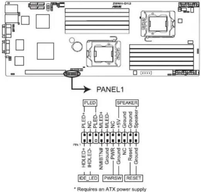
1. System power LED (3-pin PLED)
This 3-pin connector is for the system power LED. Connect the chassis power LED cable to this connector. The system power LED lights up when you turn on the system power, and blinks when the system is in sleep mode.
2. Message LED (2-pin MLED)
This 2-pin connector is for the message LED cable that connects to the front message LED. The message LED is controlled by Hardware monitor to indicate an abnormal event occurrence.
3. System warning speaker (4-pin SPEAKER)
This 4-pin connector is for the chassis-mounted system warning speaker. The speaker allows you to hear system beeps and warnings.
4. Hard disk drive activity LED (2-pin HDDLED)
This 2-pin connector is for the HDD Activity LED. Connect the HDD Activity LED cable to this connector. The IDE LED lights up or flashes when data is read from or written to the HDD.
5. Proprietary power button/soft-off button (2-pin PWRSW)
This connector is for the system power button. Pressing the power button turns the system on or puts the system in sleep or soft-off mode depending on the BIOS settings. Pressing the power switch for more than four seconds while the system is ON turns the system OFF.
6. Reset button (2-pin RESET)
This 2-pin connector is for the chassis-mounted reset button for system reboot without turning off the system power.
10. Auxiliary panel connector (20-pin AUX\_PANEL1)
This connector is for additional front panel features including front panel SMB, locator LED and switch, chassis intrusion, and LAN LEDs.
Z8NH-D12 Auxiliary panel connector
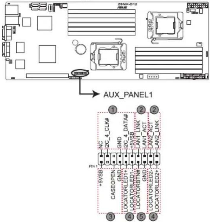
- Front panel SMB (6-1 pin FPSMB)
These leads connect the front panel SMBus cable.
- LAN activity LED (2-pin LAN1_LED, LAN2_LED)
These leads are for Gigabit LAN activity LEDs on the front panel.
- Chassis intrusion (4-1 pin CHASSIS)
These leads are for the intrusion detection feature for chassis with intrusion sensor or microswitch. When you remove any chassis component, the sensor triggers and sends a high-level signal to these leads to record a chassis intrusion event. The default setting is short CASEOPEN and GND pin by jumper cap to disable the function.
- Locator LED (2-pin LOCATORLED1 and 2-pin LOCATORLED2)
These leads are for the locator LED1 and LED2 on the front panel.
Connect the Locator LED cables to these 2-pin connector. The LEDs will light up when the Locator button is pressed.
- Locator Button/Swich (2-pin LOCATORBTN)
These leads are for the locator button on the front panel. This button queries the state of the system locator.
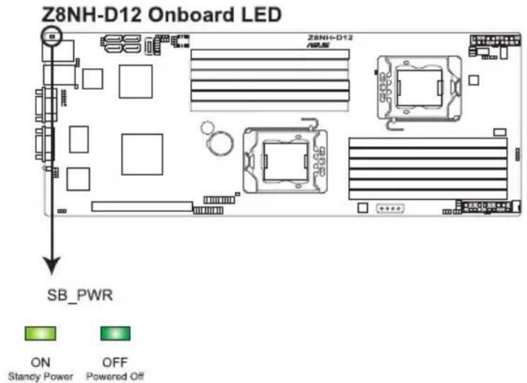
4.4 Internal LEDs
1. Standby Power LED
The motherboard comes with a standby power LED. The green LED lights up to indicate that the system is ON, in sleep mode, or in soft-off mode. This is a reminder that you should shut down the system and unplug the power cable before removing or plugging in any motherboard component. The illustration below shows the location of the onboard LED.
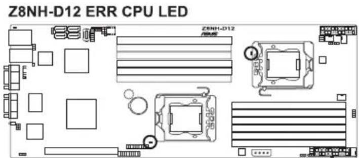
2. CPU warning LED (ERR\_CPU1, ERR\_CPU2)
The CPU warning LEDs light up to indicate that an impending failure of the corresponding CPU.
Chapter 5
This chapter tells how to change the system settings through the BIOS Setup menus. Detailed descriptions of the BIOS parameters are also provided.
natural_image
Front view of a server rack with multiple drive bays and indicator lights (no visible text or labels)BIOS setup
5.1 Managing and updating your BIOS
The following utilities allow you to manage and update the motherboard Basic Input/Output System (BIOS) setup:
- AFUDOS utility (Updates the BIOS in DOS mode using a bootable USB flash drive.)
- ASUS CrashFree BIOS 3 (To recover the BIOS using a USB flash drive when the BIOS file fails or gets corrupted.)
Refer to the corresponding sections for details on these utilities.

Save a copy of the original motherboard BIOS file to a bootable USB flash drive in case you need to restore the BIOS in the future. Copy the original motherboard BIOS using the AFUDOS utility.
5.1.1 AFUDOS utility
The AFUDOS utility allows you to update the BIOS file in DOS environment using a bootable USB flash drive with the updated BIOS file. This utility also allows you to copy the current BIOS file that you can use as backup when the BIOS fails or gets corrupted during the updating process.
Copying the current BIOS
To copy the current BIOS file using the AFUDOS utility:

- Ensure that the USB flash drive is not write-protected and has at least 2048 KB free space to save the file.
-
The succeeding BIOS screens are for reference only. The actual BIOS screen displays may not be the same as shown.
-
Copy the AFUDOS utility (afudos.exe) from the motherboard support CD to the bootable USB flash drive.
-
Boot the system in DOS mode, and then at the prompt type:
afudos /o [filename]
where the [filename] is any user-assigned filename not more than eight alphanumeric characters for the main filename and three alphanumeric characters for the extension name.
A:>afudos /oOLDBIOS1.rom
Main filename Extension name
- Press
. The utility copies the current BIOS file to the USB flash drive.
A:\>afudos /oOLDBIOS1.rom
AMI Firmware Update Utility - Version 1.19(ASUS V2.07(03.11.24BB))
Copyright (C) 2002 American Megatrends, Inc. All rights reserved.
Reading flash .... done
Write to file..... ok
A:\>
The utility returns to the DOS prompt after copying the current BIOS file.
Updating the BIOS file
To update the BIOS file using the AFUDOS utility:
- Visit the ASUS website (www.asus.com) and download the latest BIOS file for the motherboard. Save the BIOS file to a bootable USB flash drive.

Write the BIOS filename on a piece of paper. You need to type the exact BIOS filename at the DOS prompt.
- Copy the AFUDOS utility (afudos.exe) from the motherboard support CD to the bootable USB flash drive.
- Boot the system in DOS mode, and then at the prompt type:
afudos /i [filename]
where [filename] is the latest or the original BIOS file on the bootable USB flash drive, and then press
A:\>afudos /iRS702DE6.ROM
- The utility verifies the file, and then starts updating the BIOS file.
A:\>afudos /iRS702DE6.ROM
AMI Firmware Update Utility - Version 1.19(ASUS V2.07(03.11.24BB))
Copyright (C) 2002 American Megatrends, Inc. All rights reserved.

WARNING!! Do not turn off power during flash BIOS
Reading file ....... done
Reading flash ....... done

Advance Check ......
Erasing flash ....... done
Writing flash ....... 0x0008CC00 (9%)

DO NOT shut down or reset the system while updating the BIOS to prevent system boot failure!
- The utility returns to the DOS prompt after the BIOS update process is completed. Reboot the system from the hard disk drive.
A:\>afudos /iRS702DE6.ROM
AMI Firmware Update Utility - Version 1.19(ASUS V2.07(03.11.24BB))
Copyright (C) 2002 American Megatrends, Inc. All rights reserved.

WARNING!! Do not turn off power during flash BIOS
Reading file ....... done
Reading flash ....... done

Advance Check ......
Erasing flash ....... done
Writing flash ....... done
Verifying flash ....... done

Please restart your computer

A:\>
5.1.2 ASUS CrashFree BIOS 3 utility
The ASUS CrashFree BIOS 3 utility is an auto recovery tool that allows you to restore the BIOS file when it fails or gets corrupted during the updating process. You can restore a corrupted BIOS file using the motherboard support DVD or a USB flash drive that contains the BIOS file.

The BIOS file in the motherboard support DVD may be older than the BIOS file published on the ASUS official website. If you want to use the newer BIOS file, download the file at support.asus.com and save it to a USB flash drive.
Recovering the BIOS
To recover the BIOS
- Turn on the system.
- Insert the motherboard support DVD to the optical drive, or the USB flash drive containing the BIOS file to the USB port.
- The utility automatically checks the devices for the BIOS file. When found, the utility reads the BIOS file and starts flashing the corrupted BIOS file.
- Turn off the system after the utility completes the updating process and power on again.
- The system requires you to enter BIOS Setup to recover BIOS setting. To ensure system compatibility and stability, we recommend that you press
to load default BIOS values.

DO NOT shut down or reset the system while recovering the BIOS! Doing so can cause system boot failure!
5.2 BIOS setup program
This motherboard supports a programmable firmware chip that you can update using the provided utility described in section 5.1 Managing and updating your BIOS.
Use the BIOS Setup program when you are installing a motherboard, reconfiguring your system, or prompted to "Run Setup." This section explains how to configure your system using this utility.
Even if you are not prompted to use the Setup program, you can change the configuration of your computer in the future. For example, you can enable the security password feature or change the power management settings. This requires you to reconfigure your system using the BIOS Setup program so that the computer can recognize these changes and record them in the CMOS RAM of the firmware chip.
The firmware chip on the motherboard stores the Setup utility. When you start up the computer, the system provides you with the opportunity to run this program. Press during the Power-On Self-Test (POST) to enter the Setup utility; otherwise, POST continues with its test routines.
If you wish to enter Setup after POST, restart the system by pressing
The Setup program is designed to make it as easy to use as possible. Being a menu-driven program, it lets you scroll through the various sub-menus and make your selections from the available options using the navigation keys.

- The default BIOS settings for this motherboard apply for most conditions to ensure optimum performance. If the system becomes unstable after changing any BIOS settings, load the default settings to ensure system compatibility and stability. Select the Load Default Settings item under the Exit Menu. See section 5.7 Exit Menu.
- The BIOS setup screens shown in this section are for reference purposes only, and may not exactly match what you see on your screen.
- Visit the ASUS website at www.asus.com to download the latest BIOS file for this motherboard.
5.2.1 BIOS menu screen
![Menu bar Configuration fieldsMenu items General help Main Advanced Server BIOS SETUP UTILITY Boot Exit System Time [13:44:30] System Date [Thu, 01/08/2009] ► SATA 1 : [ST3160812AS] ► SATA 2 : [Not Detected] ► SATA 3 : [Not Detected] ► SATA 4 : [Not Detected] ► IDE Configuration ► AHCI Configuration ► System Information Use [ENTER], [TAB] or [SHIFT-TAB] to select a field. Use [+] or [-] to configure system Date. ←→ Select Screen ↑↓ Select Item +- Change Field Tab Select Field F1 General Help F10 Save and Exit ESC Exit v02.61 (C) Copyright 1985-2009, American Megatrends, Inc. Sub-menu items Navigation keys](/content/2026/06/1166783/images/8c20dd9976443e9a923279381377b9ef790665f0c33e787c0963815fd0c35893.jpg)
5.2.2 Menu bar
The menu bar on top of the screen has the following main items:
Main For changing the basic system configuration
Advanced For changing the advanced system settings
Server For changing the advanced server settings
Boot For changing the system boot configuration
Exit For selecting the exit options and loading default settings
To select an item on the menu bar, press the right or left arrow key on the keyboard until the desired item is highlighted.
5.2.3 Navigation keys
At the bottom right corner of a menu screen are the navigation keys for that particular menu. Use the navigation keys to select items in the menu and change the settings.

Some of the navigation keys differ from one screen to another.
5.2.4 Menu items
The highlighted item on the menu bar displays the specific items for that menu; for example, selecting Main shows the Main menu items.
The other items (Advanced, Power, Boot, and Exit) on the menu bar have their respective menu items.
5.2.5 Sub-menu items
A solid triangle before each item on any menu screen means that the item has a sub-menu. To display the sub-menu, select the item and press
5.2.6 Configuration fields
These fields show the values for the menu items. If an item is user-configurable, you can change the value of the field opposite the item. You cannot select an item that is not user-configurable.
A configurable field is enclosed in brackets, and is highlighted when selected. To change the value of a field, select it then press
5.2.7 Pop-up window
Select a menu item and press
5.2.8 Scroll bar
A scroll bar appears on the right side of a menu screen when there are items that do not fit on the screen. Press the Up/Down arrow keys or
![BIOS SETUP UTILITY Advanced CPU Bridge Chipset Configuration USB Functions USB Port Configure USB 2.0 Controller HDA Controller SMBUS Controller SLP_54# Min. Assertion Width PCIE Ports Configuration PCIE Port 0 PCIE Port 1 PCIE Port 2 PCIE Port 3 PCIE Port 4 PCIE Port 5 PCIE High Priority Port Disabled 2 USB Ports 4 USB Ports 6 USB Ports 8 USB Ports 10 USB Ports 12 USB Ports Auto] Auto] Auto] Auto] Auto] Auto] Auto] Auto] Disabled] Options Disabled 2 USB Ports 4 USB Ports 6 USB Ports 8 USB Ports 10 USB Ports 12 USB Ports Select Screen ↑↓ Select Item ←→ Change Option F1 General Bulp F10 Save and Exit ESC Exit v02.61 (C)Copyright 1905-2009, American Negatrends, Inc. Scroll bar Pop-up window](/content/2026/06/1166783/images/b408a2979802f1aa138d2b8b3a9c7ed0aaaadd93c545c8c632a2a02e6df7cbc1.jpg)
5.2.9 General help
At the top right corner of the menu screen is a brief description of the selected item.
5.3 Main menu
When you enter the BIOS Setup program, the Main menu screen appears, giving you an overview of the basic system information.
Refer to section 5.2.1 BIOS menu screen for information on the menu screen items and how to navigate through them.
| BIOS SETUP UTILITY | |
| Main Advanced Server Boot Exit | |
| System Time [13:44:30] System Date [Thu, 01/08/2009] ► SATA 1 : [ST3160812AS] ► SATA 2 : [Not Detected] ► SATA 3 : [Not Detected] ► SATA 4 : [Not Detected] ► IDE Configuration ► AHCI Configuration ► System Information | Use [ENTER], [TAB] or [SHIFT-TAB] to select a field. Use [+] or [-] to configure system Date. ←→ Select Screen ↑↓ Select Item +- Change Field Tab Select Field F1 General Help F10 Save and Exit ESC Exit |
| v02.61 (C)Copyright 1985-2009, American Megatrends, Inc. | |
5.3.1 System Time [xx:xx:xx]
Allows you to set the system time.
5.3.2 System Date [Day xx/xx/xxxx]
Allows you to set the system date.
5.3.3 SATA1-4
The BIOS automatically detects the connected IDE devices. There is a separate sub-menu for each IDE device. Select a device item, then press
| SATA 1 Device :Hard Disk Vendor :ST3160812AS Size :160.0GB LBA Mode :Supported Block Mode:16Sectors PIO Mode :4 Async DMA :MultiWord DMA-2 Ultra DMA :Ultra DMA-6 S.M.A.R.T.:Supported | Disabled: Disables LBA Mode. Auto: Enables LBA Mode if the device supports it and the devide is not already formatted with LBA Mode disabled. |
| Type [Auto] LBA/Large Mode [Auto] Block (Multi-Sector Transfer)M [Auto] PIO Mode [Auto] DMA Mode [Auto] SMART Monitoring [Auto] 32Bit Data Transfer [Enabled] | ←→ Select Screen ↑↓ Select Item +- Change Option F1 General Help F10 Save and Exit ESC Exit |
| v02.61 (C) Copyright 1985-2009, American Megatrends, Inc. | |
The BIOS automatically detects the values opposite the dimmed items (Device, Vendor, Size, LBA Mode, Block Mode, PIO Mode, Async DMA, Ultra DMA, and S.M.A.R.T. monitoring). These values are not user-configurable. These items show N/A if no IDE device is installed in the system.
Type [Auto]
Selects the type of IDE drive. Setting to [Auto] allows automatic selection of the appropriate IDE device type. Select [CDROM] if you are specifically configuring a CD-ROM drive. Select [ARMD] (ATAPI Removable Media Device) if your device is either a ZIP, LS-120, or MO drive.
Configuration options: [Not Installed] [Auto] [CDROM] [ARMD]
LBA/Large Mode [Auto]
Enables or disables the LBA mode. Setting to [Auto] enables the LBA mode if the device supports this mode, and if the device was not previously formatted with LBA mode disabled.
Configuration options: [Disabled] [Auto]
Block (Multi-Sector Transfer) M [Auto]
Enables or disables data multi-sectors transfers. When set to [Auto], the data transfer from and to the device occurs multiple sectors at a time if the device supports multi-sector transfer feature. When set to [Disabled], the data transfer from and to the device occurs one sector at a time.
Configuration options: [Disabled] [Auto]
PIO Mode [Auto]
Allows you to select the data transfer mode.
Configuration options: [Auto] [0] [1] [2] [3] [4]
DMA Mode [Auto]
Sets the DMA mode.
Configuration options: [Auto] [SWDMA0] [SWDMA1] [SWDMA2] [MWDMA0]
[MWDMA1] [MWDMA2] [UDMA0] [UDMA1] [UDMA2] [UDMA3] [UDMA4] [UDMA5] [UDMA6]
SMART Monitoring [Auto]
Sets the Smart Monitoring, Analysis, and Reporting Technology.
Configuration options: [Auto] [Disabled] [Enabled]
32Bit Data Transfer [Enabled]
Enables or disables 32-bit data transfer.
Configuration options: [Disabled] [Enabled]
5.3.4 IDE Configuration
The items in this menu allow you to set or change the configurations for the IDE devices installed in the system. Select an item then press
| Main BIOS SETUP UTILITY | |
| IDE Configuration | Options |
| SATA Configuration [Enhanced] Configure SATA as [IDE] | Disabled Compatible Enhanced |
| Hard Disk Write Protect [Disabled] IDE Detect Time Out (Sec) [35] | |
SATA Configuration [Enhanced]
Configuration options: [Disabled] [Compatible] [Enhanced]
Configure SATA as [IDE]
Sets the configuration for the Serial ATA connectors supported by the
Southbridge chip. Configuration options: [IDE] [RAID] [AHCI]
![ASUS RS704D-E6/PS8 - SATA Configuration [Enhanced] - 1](/content/2026/06/1166783/images/3ab27f6e6d5e15465e413110e1357a86b751867533801ee9235a3ca507018db3.jpg)
- If you want to use the Serial ATA hard disk drives as Parallel ATA physical storage devices, keep the default setting [IDE].
- If you want the Serial ATA hard disk drives to use the Advanced Host Controller Interface (AHCI), set this item to [AHCI]. The AHCI allows the onboard storage driver to enable advanced Serial ATA features that increases storage performance on random workloads by allowing the drive to internally optimize the order of commands.
- If you want to use LSI ^ MegaRAID or the Intel ^ Matrix Storage Technology configuration from the Serial ATA hard disk drives, set this item to [RAID].
Hard Disk Write Protect [Disabled]
Disables or enables device write protection. This will be effective only if the device is accessed through BIOS.
Configuration option: [Disabled] [Enabled]
IDE Detect Time Out (Sec) [35]
Selects the time out value for detecting ATA/ATAPI devices.
Configuration options: [0] [5] [10] [15] [20] [25] [30] [35]
5.3.5 AHCI Configuration
This menu is the section for AHCI configuration.
| Main BIOS SETUP UTILITY | |
| AHCI Settings | Some SATA CD/DVD in AHCI mode need to wait ready longer. |
| AHCI CD/DVD Boot Time out [35] | |
| SATA Port1 [Not Detected] | |
| SATA Port2 [Not Detected] | |
| SATA Port3 [Not Detected] | |
| SATA Port4 [Not Detected] | |
AHCI CD/DVD Boot Time out [35]
Selects the boot time out value for SATA CD/DVD devices in AHCI mode.
Congifuration options: [0] [5] [10] [15] [20] [25] [30] [35]
SATA Port1-4 [XXXX]
Displays the status of auto-detection of SATA devices.
| BIOS SETUP UTILITY | |
| Main | |
| SATA Port1 Device :Not Detected SATA Port0 [Auto] SMART Monitoring [Enabled] | Select the type of device connected to the system. |
SATA Port0 [Auto]
Allows you to select the type of device connected to the system.
Configuration options: [Auto] [Not Installed]
SMART Monitoring [Enabled]
Allows you to set the Self-Monitoring, Analysis and Reporting Technology.
Configuration options: [Disabled] [Enabled]
5.3.6 System Information
This menu gives you an overview of the general system specifications. The BIOS automatically detects the items in this menu.
| BIOS SETUP UTILITY | |
| AMIBIOS Version :0201 Build Date :02/25/10 | |
| Processor Speed :2400MHZ Count :1 | |
| System Memory Usable Size : 1024MB | |
| ► System Memory Information | |
AMIBIOS
Displays the auto-detected BIOS information.
Processor
Displays the auto-detected CPU specification.
System Memory
Displays the auto-detected system memory.
System Memory Information
Displays system memory information.
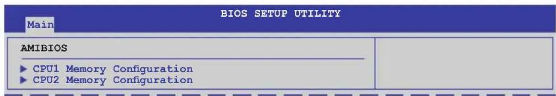
CPU1/2 Memory Configuration
Allows you to check information of installed memory (6 DIMMs per CPU).
5.4 Advanced menu
The Advanced menu items allow you to change the settings for the CPU and other system devices.

Take caution when changing the settings of the Advanced menu items. Incorrect field values can cause the system to malfunction.
| Main Advanced Server BIOS SETUP UTILITY Boot Exit | |
| CPU Configuration Chipset Configuration Legacy Device Configuration USB Configuration PCIPnP Configuration Power On Configuration Event Log Configuration Hardware Monitor I/O Virtualization PCI Express Configuration ACPI Configuration | Configure CPU. ←→ Select Screen ↑↓ Select Item Enter Go to Sub Screen F1 General Help F10 Save and Exit ESC Exit |
| v02.61 (C) Copyright 1985-2009, American Megatrends, Inc. | |
5.4.1 CPU Configuration
The items in this menu show the CPU-related information that the BIOS automatically detects. Some items may not appear if your CPU does not support the related functions.
![BIOS SETUP UTILITY Advanced Configure advanced CPU settings Module Version:01.08 Manufacturer:Intel Brand String:Intel(R) Xeon(R) CPU L5640 @ 2.27GHz Frequency :2.26GHz BCLK Speed :133MHz Cache L1 :384 KB Cache L2 :1536 KB Cache L3 :12288 KB Ratio Status:Unlocked (Min:12, Max:17) Ratio Actual Value :17 Ratio CMOS Setting: [17] C1E Support [Enabled] Hardware Prefetcher [Enabled] Adjacent Cache Line Prefetch [Enabled] MPS and ACPI MADT ordering [Modern ordering] Max CPUID Value Limit [Disabled] Intel(R) Virtualization Tech [Enabled] Sets the ratio between CPU Core Clock and the FSB Frequency. Note:If an invalid ratio is set in CMOS then actual and setpoint values may differ. ←→ Select Screen ↑↓ Select Item F1 General Help F10 Save and Exit ESC Exit v02.61 (C) Copyright 1985-2009, American Megatrends, Inc.](/content/2026/06/1166783/images/24795f206b96f916331eec133316173b483716356ee08ebe6d74513eebac1bca.jpg)
Scroll down for more items.
CPU TM Function [Enabled]
Execute-Disable Bit Capability [Enabled]
Intel(R) HT Technology [Disabled]
Active Processor Cores [All]
A20M [Disabled]
Intel(R) SpeedStep(TM) Tech [Enabled]
Intel(R) TurboMode tech [Enabled]
Intel(R) C-STATE Tech [Enabled]
C3 State [ACPI C3]
C6 State [Enabled]
C State package limit setting [Auto]
C1 Auto Demotion [Enabled]
C3 Auto Demotion [Enabled]
ACPI T State [Disabled]
v02.61 (C) Copyright 1985-2009, American Megatrends, Inc.
Ratio CMOS Setting [17]
Allows you to adjust the ratio between CPU Core Clock and BCLK Frequency.
Use the <+> and <-> keys to adjust the value.
Configuration options: [12.0] [13.0] [14.0] [15.0] [16.0] [17.0]]
C1E Support [Enabled]
Allows you to enable or disable Enhanced Halt State support.
Configuration options: [Disabled] [Enabled]
Hardware Prefetcher [Enabled]
Allows you to enable or disable the Hardware Prefetcher function.
Configuration options: [Disabled] [Enabled]
Adjacent Cache Line Prefetch [Enabled]
Allows you to enable or disable the Adjacent Cache Line Prefetch function.
Configuration options: [Disabled] [Enabled]
MPS and ACPI MADT ordering [Modern ordering]
Allows you to select the ordering according to the operating system you install.
Select [Modern ordering] for Windows XP or later OS versions and [Legacy ordering] for Windows 2000 or earlier OS version.
Configuration options: [Modern ordering] [Legacy ordering]
Max CPUID Value Limit [Disabled]
Setting this item to [Enabled] allows legacy operating systems to boot even without support for CPUs with extended CPUID functions.
Configuration options: [Disabled] [Enabled]
Intel(R) Virtualization Tech [Enabled]
The Intel® Virtualization Technology allows a hardware platform to run multiple operating systems separately and simultaneously, enabling one system to virtually function as several systems. Configuration options: [Disabled] [Enabled]
CPU TM Function [Enabled]
This function enables the overheated CPU to throttle the clock speed to cool down. Configuration options: [Disabled] [Enabled]
Execute-Disable Bit Capability [Enabled]
Allows you to enable or disable the No-Execution Page Protection Technology. Setting this item to [Disabled] forces the XD feature flag to always return to zero (0). Configuration options: [Disabled] [Enabled]
Intel(R) HT Technology [Enabled]
Allows you to enable or disable the Intel Hyper-Threading Technology function. When disabled, only one thread per activated core is enabled. Configuration options: [Enabled] [Disabled]
Active Processor Cores [All]
Allows you to choose the number of CPU cores to activate in each processor package.Configuration options: [All] [1] [2]
A20M [Disabled]
Legacy OSes and APs may need A20M enabled. Configuration options: [Disabled] [Enabled]
Intel(R) SpeedStep (TM) Tech [Enabled]
When set to [Disabled], the CPU runs at its default speed. When set to [Enabled], the CPU speed is controlled by the operating system. Configuration options: [Disabled] [Enabled]
Intel(R) TurboMode tech [Enabled]
The turbo mode allows the processor cores to run faster than the marked frequency in specific condition. Configuration options: [Disabled] [Enabled]
Intel(R) C-STATE Tech [Enabled]
The Intel ^® C-State Technology allows the CPU to save more power under idle mode. Enable this item only when you install a C-State Technology-supported CPU. Configuration options: [Disabled] [Enabled]
![ASUS RS704D-E6/PS8 - Intel(R) C-STATE Tech [Enabled] - 1](/content/2026/06/1166783/images/7df8e939f07ea79865b98eba7989a06932825fbf6c0b102febe23db81eb94a1b.jpg)
The following items appear only when you set the Intel(R) C-STATE Tech item to [Enabled].
C3 State [ACPI C3]
Allows you to select Nehalem C state action.
Configuratiton options: [Disabled] [ACPI C2] [ACPI C3]
C6 State [Enabled]
Allows you to select Nehalem C state action.
Configuratiton options: [Disabled] [Enabled]
C State package limit setting [Auto]
We recommend that you set this item to [Auto] for BIOS to automatically detect the
C-State mode supported by your CPU.
Configuration options: [Auto] [C1] [C3] [C6]
C3 Auto Demotion [Enabled]
When this item is enabled, the CPU will conditionally demote C6 requests to C3 based on the uncore auto-demote information.
Configuration options: [Disabled] [Enabled]
ACPI T State [Disabled]
Enables or disables processor throttling report in ACPI.
Configuration options: [Disabled] [Enabled]
5.4.2 Chipset Configuration
The Chipset configuration menu allows you to change advanced chipset settings. Select an item then press
| BIOS SETUP UTILITY Advanced | |
| Advanced Chipset Settings WARNING: Setting wrong values in below sections may cause system to malfunction. ►CPU Bridge Configuration ►North Bridge Configuration ►South Bridge Configuration ►Intel VT-d Configuration | Configure North Bridge features. ←→ Select Screen ↑↓ Select Item Enter Go to Sub Screen F1 General Help F10 Save and Exit ESC Exit |
| v02.61 (C) Copyright 1985-2009, American Megatrends, Inc. | |
CPU Bridge Chipset Configuration
![BIOS SETUP UTILITY Advanced CPU Bridge Chipset Configuration CPU Revision :B0 Current CSI Frequency :5.866GT Current Memory Frequency :1066 Mhz CSI Links Speed [Full-Speed] CSI Frequency [Auto] CSI Isochronous [Disabled] CSI L1 [Enabled] CSI Power Optimization Policy [Static] Memory Frequency [Auto] Memory Mode [Independent] Memory ECC Function [Enabled] Double Rate Refresh [Auto] Demand Scrubbing [Enabled] Patrol Scrubbing [Disabled] NUMA Aware [Auto] Page Policy [Open] To transition the CSI links to full-speed or leave them in slow-mode. ←→ Select Screen ↑↓ Select Item +- Change Option F1 General Help F10 Save and Exit ESC Exit v02.61 (C) Copyright 1985-2009, American Megatrends, Inc.](/content/2026/06/1166783/images/efd72ff4ac4cc340bffe0ea7c3d648d69711e437c0ec58dcd5c65cac2e5e9157.jpg)
Scroll down for more items.
![Adaptive Page [Disabled] Data Scramble [Enabled] Split Below 4GB [Disabled] Channel Interleaving [6:1] Rank Interleaving [4:1] Memory Thermal Throttling [Disabled] Force VDD 1.5V [Disabled]](/content/2026/06/1166783/images/3b35abc0ac1b5cd898f9b6c24db0aa1ee35bef67d5f6540bd4e210d6a67be11f.jpg)
CSI Links Speed [Full-Speed]
Allows you to set the speed of CSI Links.
Configuration options: [Slow-Mode] [Full-Speed]
CSI Frequency [Auto]
Allows you to set the CSI frequency.
Configuration options: [Auto] [4.800GT] [5.866GT] [6.400GT]
CSI Isochronous [Disabled]
Configuration options: [Disabled] [Enabled]
CSI L1 [Disabled]
Configuration options: [Disabled] [Enabled]
CSI Power Optimization Policy [Static]
Configuration options: [Adaptive] [Static] [Bypass]
Memory Frequency [Auto]
You may allow the system to detect DDR3 memory frequency via SPD or designate a specific frequency.
Configuration options: [Auto] [Force DDR-800] [Force DDR-1066]
[Force DDR-1333]
Memory Mode [Independent]
Allows you to set Memory channel mode.
Configuration options: [Independent] [Channel Mirroring] [Lockstep]
Memory ECC Function [Enabled]
Allows you to enable or disable Memory ECC function.
Configuration options: [Disabled] [Enabled]
Double Rate Refresh [Auto]
Configuration options: [Disabled] [Auto]
Demand Scrubbing [Enabled]
Enables or disables the ECC demand scrub.
Configuration options: [Disabled] [Enabled]
Patrol Scrubbing [Disabled]
Enables or disables the ECC patrol scrub.
Configuration options: [Disabled] [Enabled]
NUMA Aware [Auto]
Configuration options: [Disabled] [Enabled]
Page Poilcy [Open]
Configuration options: [Closed] [Open]
Adaptive Page [Disabled]
Configuration options: [Disabled] [Enabled]
Data Scramble [Enabled]
Configuration options: [Disabled] [Enabled]
Split Below 4 GB [Disabled]
Configuration options: [Disabled] [Auto]
Channel Interleaving [6:1]
Allows you to set the channel interleaving setting.
Configuration options: [1:1] [2:1] [4:1] [6:1]
Rank Interleaving [4:1]
Allows you to set the rank interleaving setting.
Configuration options: [1:1] [2:1] [4:1]
Memory Thermal Throttling [Disabled]
[CLTT] is for closed loop thermal throttling and [OLTT] for open loop thermal throttling. Configuration options: [CLTT] [OLTT] [Disabled] [Auto]
Force VDD 1.5V [Disabled]
Configuration options: [Disabled] [Enabled]
North Bridge Configuration
The North Bridge Configuration menu shows the auto-detected Northbridge values.
| BIOS SETUP UTILITY Advanced | |
| NorthBridge Chipset Configuration | |
| NB Revision :C2 | |
| Current CSI Frequency :5.866GT | |
South Bridge Chipset Configuration
| BIOS SETUP UTILITY Advanced | |
| CPU Bridge Chipset Configuration | Options |
| USB Functions [Enabled] | Disabled |
| USB Port Configure [8+4 USB Ports] | Enabled |
| USB 2.0 Controller [Enabled] | |
| SLP_S4# Min. Assertion Width [1 to 2 seconds] | |
USB Functions [Enabled]
Allows you to configure the amount of USB ports to be enabled.
Configuration options: [Disabled] [Enabled]
USB Port Configure [8+4 USB Ports]
This item disappears when you set the USB Functions item to [Disabled].
Configuration options: [6+6 USB Ports] [8+4 USB Ports]
USB 2.0 Controller [Enabled]
Allows you to enable or disable the USB 2.0 controller.
Configuration options: [Enabled] [Disabled]
SLP\_S4# Min. Assertion Width [1 to 2 seconds]
Configuration options: [4 to 5 seconds] [3 to 4 seconds] [2 to 3 seconds] [1 to 2 seconds]
Intel VT-d Configuration
![BIOS SETUP UTILITY Advanced Intel VT-d [Disabled] Options Disabled Enabled](/content/2026/06/1166783/images/9d86bc8e06c0abbf162c0223008dcd31c2813c1a9fa7d8c13acab6512169dae9.jpg)
Intel VT-d [Disabled]
Allows you to enable or disable the Intel Virtualization Technology for Directed I/O.
Configuration options: [Disabled] [Enabled]
5.4.3 Legacy Device Configuration
| BIOS SETUP UTILITY Advanced | |
| Legacy Device Configuration Serial Port1 Address [3F8/IRQ4] Serial Port2 Address [2F8/IRQ3] | Allows BIOS to Select Serial Port1 Base Address. Select Screen ↑↓ Select Item +- Change Option F1 General Help F10 Save and Exit ESC Exit |
| v02.61 (C)Copyright 1985-2009, American Megatrends, Inc. | |
Serial Port1 Address [3F8/IRQ4]
Allows you to select the Serial Port1 base address.
Configuration options: [Disabled] [3F8/IRQ4] [3E8/IRQ4] [2E8/IRQ3]
Serial Port2 Address [2F8/IRQ3]
Allows you to select the Serial Port2 base address.
Configuration options: [Disabled] [2F8/IRQ3] [3E8/IRQ4] [2E8/IRQ3]
5.4.4 USB Configuration
| BIOS SETUP UTILITY Advanced | |
| USB Configuration Module Version - 2.24.3-13.4 USB Devices Enabled: None Legacy USB Support [Enabled] USB 2.0 Controller Mode [HiSpeed] BIOS EHCI Hand-Off [Enabled] | Enables support for legacy USB. AUTO option disables legacy support if no USB devices are connected. ←→ Select Screen ↑↓ Select Item +- Change Option F1 General Help F10 Save and Exit ESC Exit |
| v02.61 (C) Copyright 1985-2009, American Megatrends, Inc. | |

The following item appears only when you set USB Function to [Enabled].
Legacy USB Support [Enabled]
Allows you to enable or disable support for legacy USB devices. Setting to [Auto] allows the system to detect the presence of USB devices at startup. If detected, the USB controller legacy mode is enabled. If no USB device is detected, the legacy USB support is disabled. Configuration options: [Disabled] [Enabled] [Auto]
![ASUS RS704D-E6/PS8 - Legacy USB Support [Enabled] - 1](/content/2026/06/1166783/images/8e69b6b57a3572ec4ffdebc6395075f413af26e0e96eebea4a73946c827e247d.jpg)
The following item appears only when you set USB Function to [Enabled].
USB 2.0 Controller Mode [HiSpeed]
Allows you to set the USB 2.0 controller to HiSpeed (480Mbps) or FullSpeed (12Mbps). Configuration options: [FullSpeed] [HiSpeed]
BIOS EHCI Hand-Off [Enabled]
Enables or disables the BIOS EHCI hand-off support. Configuration options: [Disabled] [Enabled]
5.4.5 PCIPnP Configuration
The PCIPnP Configuration menu items allow you to change the advanced settings for PCI/PnP devices.

Take caution when changing the settings of the PCI/PnP Configuration menu items. Incorrect field values can cause the system to malfunction.
| Advanced PCI/PnP Settings WARNING: Setting wrong values in below sections may cause system to malfunction. Plug And Play O/S [No] PCI Option ROM Scan Order [Bus 0 First] Onboard Option ROM Priority [High] Onboard LAN1 Chip [Enabled] Onboard LAN2 Chip [Enabled] Onboard LAN1 Boot [PXE] Onboard LAN2 Boot [PXE] | NO: lets the BIOS configure all the devices in the system. YES: lets the operating system configure Plug and Play (PnP) devices not required for boot if your system has a Plug and Play operating system. Select Screen ↑↓ Select Item +- Change Option F1 General Help F10 Save and Exit ESC Exit |
| v02.61 (C)Copyright 1985-2009, American Megatrends, Inc. | |
Plug And Play O/S [No]
When set to [No], BIOS configures all the devices in the system. When set to [Yes] and if you install a Plug and Play operating system, the operating system configures the Plug and Play devices not required for boot.
Configuration options: [No] [Yes]
PCI Option ROM Scan Order [Bus 0 First]
Allows you to select the PCI option ROM scanning order. The scanning of the option ROM will start from the lowest bus, device, function number if you set this item to [Bus 0 First]; the scanning starts from the highest bus, device, function number if you set this item to [Bus N First].
Configuration options: [Bus 0 First] [Bus N First]
Onboard Option ROM Priority [High]
Allows you to select the onboard option ROM priority.
Configuration options: [Normal] [High]
Onboard LAN1/2 Chip [Enabled]
Allows you to enable or disable the onboard LAN1/2 chip.
Configuration: [Disabled] [Enabled]
Onboard LAN1/2 Boot [PXE]
Allows you to configure the onboard LAN1/2 boot mode.
Configuration: [Disabled] [PXE] [iSCSI]
5.4.6 Power On configuration
![BIOS SETUP UTILITY Advanced APM Configuration Restore on AC Power Loss [Last State] Resume On Ring [Disabled] Resume On PME#(Wake On LAN) [Disabled] Resume On RTC Alarm [Disabled] Options Power Off Power On Last State ←→ Select Screen ↑↓ Select Item +- Change Option F1 General Help F10 Save and Exit ESC Exit v02.61 (C)Copyright 1985-2009, American Megatrends, Inc.](/content/2026/06/1166783/images/3883a99b6c5908be080824d22b15ce023c163734d4bf18805d1212897f24a21b.jpg)
Restore on AC Power Loss [Last State]
When set to [Power Off], the system goes into off state after an AC power loss. When set to [Power On], the system will reboot after an AC power loss. When set to [Last State], the system goes into either off or on state, whatever the system state was before the AC power loss.
Configuration options: [Power Off] [Power On] [Last State]
Resume On Ring [Disabled]
When set to [Enabled], the system enables RI to generate a wake event while the computer is in Soft-off mode. Configuration options: [Disabled] [Enabled]
Resume On PME#(Wake On LAN) [Disabled]
When set to [Enabled], the system enables PME to generate a wake event while the computer is in Soft-off mode. Configuration options: [Disabled] [Enabled]
Resume On RTC Alarm [Disabled]
Allows you to enable or disable RTC to generate a wake-up event.
Configuration options: [Disabled] [Enabled]
![ASUS RS704D-E6/PS8 - Resume On RTC Alarm [Disabled] - 1](/content/2026/06/1166783/images/90aa3aeccd01edb22c1e0f6d0b0331239072a6cbb71d06b9f82f122e2be6c088.jpg)
The following items appear only when the Resume On RTC Alarm item is set to [Enabled].
RTC Alarm Date [15]
To set the alarm date, highlight this item and press the <+> or <-> key to make the selection.
System Time [12:30:30]
Use the
5.4.7 Event Log Configuration
| BIOS SETUP UTILITY Advanced | |
| Event Logging details View Event Log Clear Event Log | View all unread events on the Event log. Select Screen ↑↓ Select Item Enter Go to Sub Screen F1 General Help F10 Save and Exit ESC Exit |
| v02.61 (C) Copyright 1985-2009, American Megatrends, Inc. | |
View Event Log
Press
Clear Event Log
Press
5.4.8 Hardware Monitor
![BIOS SETUP UTILITY Advanced Hardware Monitor CPU1 Temperature [ 27.5°C/ 81.5°F] CPU2 Temperature [ 0 °C/ 32 °F] Front Fan1 Speed [5357RPM ] Front Fan2 Speed [ N/A ] Front Fan3 Speed [ N/A ] Front Fan4 Speed [ N/A ] Fan Speed Control [High Density Mode] VCORE1 Voltage [ 1.052 V] VCORE2 Voltage [ N/A ] +1.5V_P1DDR3 Voltage [ 1.508 V] +1.5V_P2DDR3 Voltage [ N/A ] +1.5V_ICH Voltage [ 1.520 V] P1VTT Voltage [ 1.022 V] P2VTT Voltage [ 1.022 V] +1.1V_IOH Voltage [ 0.204 V] +12VVoltage [12.000 V] +5V Voltage [ 5.196 V] +3.3V Voltage [ 3.246 V] Options Disabled Enabled ←→ Select Screen ↑↓ Select Item +- Change Option F1 General Help F10 Save and Exit ESC Exit v02.61 (C) Copyright 1985-2009, American Megatrends, Inc.](/content/2026/06/1166783/images/f034706cc425345ccd65de939f5d5f2dcfbaf4445f7a25782ef02d618e4b06d1.jpg)
Scroll down for more items.
![+5VSB Voltage [ 5.132 V] +3VSB Voltage [ 3.198 V] VBAT Voltage [ 3.126 V] v02.61 (C) Copyright 1985-2009, American Megatrends, Inc.](/content/2026/06/1166783/images/78180460a46b99ad2bcdd5cad0caea70f9b10fdc0c3b2b7b7839f004b94296cb.jpg)
CPU1/2 Temperature [xxx°C/xxx°F]
The onboard hardware monitor automatically detects and displays the CPU temperatures. Select [Ignored] if you do not wish to display the detected temperatures.
Front Fan1-4 Speed [xxxxRPM] or [Ignored] / [N/A]
The onboard hardware monitor automatically detects and displays the speed of CPU fans, front fans, and rear fans in rotations per minute (RPM). If the fan is not connected to the motherboard, the field shows [N/A].
Fan Speed Control [High Density Mode]
Allows you to configure the ASUS Smart Fan feature that smartly adjusts the fan speeds for more efficient system operation.
Configuration options: [Full Speed Mode] [Whisper Mode] [Generic Mode] [High Density Mode]
VCORE1/2 Voltage, +1.5V_P1/2DDR3 Voltage, +1.5V_ICH Voltage, P1/2VTT Voltage, +1.1V_IOH Voltage, +12V Voltage, +5V Voltage, +3.3V Voltage, +5VSB Voltage, +3VSB Voltage, VBAT Voltage
The onboard hardware monitor automatically detects the voltage output through the onboard voltage regulators. Select [Ignored] if you do not want to detect this item.
5.4.9 I/O Virtualization
![BIOS SETUP UTILITY Advanced Configure I/O Virtualization Parameters SR-IOV Supported [Disabled] Options Enabled Disabled ←→ Select Screen ↑↓ Select Item +- Change Option F1 General Help F10 Save and Exit ESC Exit v02.61 (C) Copyright 1985-2009, American Megatrends, Inc.](/content/2026/06/1166783/images/c06fb86764898aac42f0a8769760ebf9e8f594b3c417ee8dce2520098bd064ee.jpg)
SR-IOV Supported [Disabled]
Configuration options: [Disabled] [Enabled]
5.4.10 PCI Express Configuration
| Advanced BIOS SETUP UTILITY | |
| PCI Express Configuration Active State Power-Management [Disabled] | Enable/Disable PCI Express L0s and L1 link power states. ←→ Select Screen ↑↓ Select Item +- Change Option F1 General Help F10 Save and Exit ESC Exit |
| v02.61 (C) Copyright 1985-2009, American Megatrends, Inc. | |
Active State Power-Management [Disabled]
Enables or disables the PCI Express L0s and L1 link power states.
Configuration options: [Disabled] [Enabled]
5.4.11 ACPI Configuration
| BIOS SETUP UTILITY Advanced | |
| ACPI Settings ► Advanced ACPI Configuration ► Chipset ACPI Configuration ► General WHEA Configuration | Advanced ACPI Configuration settings. Use this section to configure additional ACPI options. ←→ Select Screen ↑↓ Select Item Enter Go to Sub Screen F1 General Help F10 Save and Exit ESC Exit |
| v02.61 (C) Copyright 1985-2009, American Megatrends, Inc. | |
Advanced ACPI Configuration
| BIOS SETUP UTILITY Advanced | |
| Advanced ACPI Configuration ACPI 2.0 Support [Enabled] ACPI APIC support [Enabled] BIOS-->AML ACPI table [Enabled] Headless mode [Disabled] | Add additional tables as per ACPI 2.0 specifications. |
ACPI 2.0 Support [Enabled]
Specifies the Advanced Configuration and Power Interface (ACPI) version supported.
Configuration options: [Disabled] [Enabled]
ACPI APIC Support [Enabled]
Allows you to enable or disable the Advanced Configuration and Power Interface (ACPI) support in the Advanced Programmable Interrupt Controller (APIC). When set to Enabled, the ACPI APIC table pointer is included in the RSDT pointer list. Configuration options: [Disabled] [Enabled]
BIOS-->AML ACPI table [Enabled]
Allows you to include the BIOS-->AML exchange table pointer to (X)RSDT pointer list.
Configuration options: [Disabled] [Enabled]
Headless mode [Disabled]
Allows you to enable or disable the Headless operation mode through ACPI.
Configuration options: [Disabled] [Enabled]
Chipset ACPI Configuration
| BIOS SETUP UTILITY Advanced | |
| South Bridge ACPI Configuration | Options |
| APIC ACPI SCI IRQ [Disabled] High Performance Event Timer [Enabled] HPET Memory Address [FED00000h] | Enabled Disabled |
APIC ACPI SCI IRQ [Disabled]
Allows you to enable or disable the APIC ACPI SCI IRQ feature.
Configuration options: [Disabled] [Enabled]
High Performance Event Timer [Enabled]
Allows you to enable or disable the High Performance Event Timer feature.
Configuration options: [Disabled] [Enabled]
HPET Memory Address [FED00000h]
Allows you to select the HPET Memory address.
Configuration options: [FED00000h] [FED01000h] [FED02000h] [FED03000h]
General WHEA Configuration
| BIOS SETUP UTILITY Advanced | |
| General WHEA Configuration WHEA Support [Enabled] | Enable or disable Windows Hardware Error Architecture. |
WHEA Support [Enabled]
Allows you to enable or disable the Windows Hardware Error Architecture (WHEA) support.
Configuration options: [Disabled] [Enabled]
5.5 Server menu
The Server menu items allow you to customize the server features.
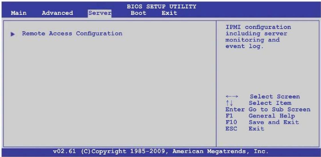
5.5.1 Remote Access Configuration
The items in this menu allows you to configure the Remote Access features. Select an item then press
| BIOS SETUP UTILITY Server | |
| Configure Remote Access type and parameters | Select Remote Access type. |
| Remote Access [Enabled] | |
| Serial port number [COM2] Base Address, IRQ [2F8h, 3] Serial Port Mode [57600 8,n,1] Flow Control [Hardware] Redirection After BIOS POST [Disabled] Terminal Type [VT-UTF8] | |
Remote Access [Enabled]
Enables or disables the remote access feature.
Configuration options: [Disabled] [Enabled]
![ASUS RS704D-E6/PS8 - Remote Access [Enabled] - 1](/content/2026/06/1166783/images/ad82db4d728f0761b8b7d5d4151574d5038893ccf4bbeffaf1764a662327b834.jpg)
The following items appear only when Remote Access is set to [Enabled].
Serial port number [COM2]
Selects the serial port for console redirection.
Configuration options: [COM1] [COM2]
Base Address. IRQ [2F8h, 3]
This item is not user-configurable and changes with the configuration of
Serial port number.
Serial Port Mode [57600 8,n,1]
Sets the Serial port mode.
Configuration options: [115200 8,n,1] [57600 8,n,1] [38400 8,n,1] [19200 8,n,1]
[09600 8,n,1]
Flow Control [Hardware]
Allows you to select the flow control for console redirection.
Configuration options: [None] [Hardware] [Software]
Redirection After BIOS POST [Disabled]
Sets the redirection mode after the BIOS Power-On Self-Test (POST). Some operating system may not work when set to [Always].
Configuration options: [Disabled] [Boot Loader] [Always]
Terminal Type [VT-UTF8]
Allows you to select the target terminal type.
Configuration options: [ANSI] [VT100] [VT-UTF8]
5.6 Boot menu
The Boot menu items allow you to change the system boot options. Select an item then press
| Main Advanced Server BIOS SETUP UTILITY Boot Exit | |
| Boot Settings ► Boot Device Priority ► Boot Settings Configuration ► Security | Specifies the Boot Device Priority sequence. A virtual floppy disk drive (Floppy Drive B: ) may appear when you set the CD-ROM drive as the first boot device. ←→ Select Screen ↑↓ Select Item Enter Go to Sub Screen F1 General Help F10 Save and Exit ESC Exit |
| v02.61 (C) Copyright 1985-2009, American Megatrends, Inc. | |
5.6.1 Boot Device Priority
| BIOS SETUP UTILITY Boot | |
| Boot Device Priority | Specifies the Boot Device Priority sequence. A device enclosed in parenthesis has been disabled in the corresponding type menu. ←→ Select Screen ↑↓ Select Item +- Change Option F1 General Help F10 Save and Exit ESC Exit |
| 1st Boot Device [Removable Dev.] 2nd Boot Device [ATAPI CD-ROM] 3rd Boot Device [Hard Drive] 4th Boot Device [Network:IBA GE Slo] 5th Boot Device [Network:IBA GE Slo] | |
| v02.61 (C) Copyright 1985-2009, American Megatrends, Inc. | |
1st \~ xxth Boot Device [XXXXXXX]
These items specify the boot device priority sequence from the available devices. The number of device items that appears on the screen depends on the number of devices installed in the system.
Configuration options: [xxxxx Drive] [Disabled]
5.6.2 Hard Disk Drives; CDROM Drives
These two items appear only when you install more than two hard disk drives or optical drives to you system. These items allows you to specify the boot priority sequence of the hard disk drives or the optical drives.
5.6.3 Boot Settings Configuration
| BIOS SETUP UTILITY Boot | |
| Boot Settings Configuration Quick Boot [Enabled] Full Screen Logo [Disabled] AddOn ROM Display Mode [Force BIOS] Bootup Num-Lock [On] Wait For 'F1' If Error [Enabled] Hit 'DEL' Message Display [Enabled] Interrupt 19 Capture [Enabled] | Allows BIOS to skip certain tests while booting. This will decrease the time needed to boot the system. ←→ Select Screen ↑↓ Select Item +- Change Option F1 General Help F10 Save and Exit ESC Exit |
| v02.61 (C)Copyright 1985-2009, American Megatrends, Inc. | |
Quick Boot [Enabled]
Enabling this item allows the BIOS to skip some power on self tests (POST) while booting to decrease the time needed to boot the system. When set to [Disabled], BIOS performs all the POST items.
Configuration options: [Disabled] [Enabled]
Full Screen Logo [Disabled]
Allows you to enable or disable the full screen logo display feature.
Configuration options: [Disabled] [Enabled]
![ASUS RS704D-E6/PS8 - Full Screen Logo [Disabled] - 1](/content/2026/06/1166783/images/51e78b24ee8465704f7e31f171341bf9288203c800f0f6bbc5aad0a9f3772f44.jpg)
Set this item to [Enabled] to use the ASUS MyLogo2™ feature.
AddOn ROM Display Mode [Force BIOS]
Allows you to set the display mode for Options ROM.
Configuration options: [Force BIOS] [Keep Current]
Bootup Num-Lock [On]
Allows you to select the power-on state for the NumLock.
Configuration options: [Off] [On]
Wait For 'F1' If Error [Enabled]
When set to [Enabled], the system waits for the
Hit 'DEL' Message Display [Enabled]
When set to [Enabled], the system displays the message "Press DEL to run Setup" during POST. Configuration options: [Disabled] [Enabled]
Interrupt 19 Capture [Enabled]
When set to [Enabled], this function allows the option ROMs to trap Interrupt 19.
Configuration options: [Disabled] [Enabled]
5.6.4 Security
The Security menu items allow you to change the system security settings. Select an item then press
| Security Settings | _to change password. <Enter> again to disable password. |
| Supervisor Password : Not Installed User Password : Not Installed | |
| Change Supervisor Password Change User Password | ←→ Select Screen ↑↓ Select Item Enter Change F1 General Help F10 Save and Exit ESC Exit |
| v02.61 (C)Copyright 1985-2009, American Megatrends, Inc. | |
Change Supervisor Password
Select this item to set or change the supervisor password. The Supervisor Password item on top of the screen shows the default Not Installed. After you set a password, this item shows Installed.
To set a Supervisor Password:
- Select the Change Supervisor Password item and press
. - From the password box, type a password composed of at least six letters and/or numbers, then press
. - Confirm the password when prompted.
The message "Password Installed" appears after you successfully set your password.
To change the supervisor password, follow the same steps as in setting a user password.
To clear the supervisor password, select the Change Supervisor Password then press

If you forget your BIOS password, you can clear it by erasing the CMOS Real Time Clock (RTC) RAM. See section 4.2 Jumpers for information on how to erase the RTC RAM.
After you have set a supervisor password, the other items appear to allow you to change other security settings.
| Supervisor Password : Installed User Password : Not Installed Change Supervisor Password User Access Level [Full Access] Change User Password Password Check [Setup] | <Enter> to change password. <Enter> again to disable password. |
User Access Level [Full Access]
This item allows you to select the access restriction to the Setup items. Configuration options: [No Access] [View Only] [Limited] [Full Access]
No Access prevents user access to the Setup utility.
View Only allows access but does not allow change to any field.
Limited allows changes only to selected fields, such as Date and Time.
Full Access allows viewing and changing all the fields in the Setup utility.
Change User Password
Select this item to set or change the user password. The User Password item on top of the screen shows the default Not Installed. After you set a password, this item shows Installed.
To set a User Password:
- Select the Change User Password item and press
. - On the password box that appears, type a password composed of at least six letters and/or numbers, then press
. - Confirm the password when prompted.
The message "Password Installed" appears after you set your password successfully.
To change the user password, follow the same steps as in setting a user password.
Password Check [Setup]
When set to [Setup], BIOS checks for user password when accessing the Setup utility. When set to [Always], BIOS checks for user password both when accessing Setup and booting the system. Configuration options: [Setup] [Always]
5.7 Exit menu
The Exit menu items allow you to load the optimal or failsafe default values for the BIOS items, and save or discard your changes to the BIOS items.
| Main Advanced Server BIOS SETUP UTILITY Boot Exit | |
| Exit Options Exit & Save Changes Exit & Discard Changes Discard Changes Load Setup Defaults | Exit system setup after saving the changes. F10 key can be used for this operation. ←→ Select Screen ↑↓ Select Item Enter Go to Sub Screen F1 General Help F10 Save and Exit ESC Exit |
| v02.61 (C) Copyright 1985-2009, American Megatrends, Inc. | |

Pressing
Exit & Save Changes
Once you are finished making your selections, choose this option from the Exit menu to ensure the values you selected are saved to the CMOS RAM. An onboard backup battery sustains the CMOS RAM so it stays on even when the PC is turned off. When you select this option, a confirmation window appears. Select YES to save changes and exit.

If you attempt to exit the Setup program without saving your changes, the program prompts you with a message asking if you want to save your changes before exiting. Press
Exit & Discard Changes
Select this option only if you do not want to save the changes that you made to the Setup program. If you made changes to fields other than System Date, System Time, and Password, the BIOS asks for a confirmation before exiting.
Discard Changes
This option allows you to discard the selections you made and restore the previously saved values. After selecting this option, a confirmation appears. Select YES to discard any changes and load the previously saved values.
Load Setup Defaults
This option allows you to load the default values for each of the parameters on the Setup menus. When you select this option or if you press
Chapter 6
This chapter provides instructions for setting up, creating and configuring RAID sets using the available utilities.

natural_image
Front view of a server rack with multiple drive bays and indicator lights (no visible text or labels)RAID confruration
6.1 Setting up RAID
The motherboard comes with the Intel ^® ICH10R southbridge controller that supports the following SATA RAID solutions:
• LSI MegaRAID software RAID Configuration Utility (default) with RAID 0, RAID 1, and RAID 10 support (for both Linux and Windows OS).
• Intel Matrix Storage Manager with RAID 0, RAID 1, RAID 10, and RAID 5 support (for Windows OS only).
6.1.1 RAID definitions
RAID 0 (Data striping) optimizes two identical hard disk drives to read and write data in parallel, interleaved stacks. Two hard disks perform the same work as a single drive but at a sustained data transfer rate, double that of a single disk alone, thus improving data access and storage. Use of two new identical hard disk drives is required for this setup.
RAID 1 (Data mirroring) copies and maintains an identical image of data from one drive to a second drive. If one drive fails, the disk array management software directs all applications to the surviving drive as it contains a complete copy of the data in the other drive. This RAID configuration provides data protection and increases fault tolerance to the entire system. Use two new drives or use an existing drive and a new drive for this setup. The new drive must be of the same size or larger than the existing drive.
RAID 10 is data striping and data mirroring combined without parity (redundancy data) having to be calculated and written. With the RAID 10 configuration you get all the benefits of both RAID 0 and RAID 1 configurations. Use four new hard disk drives or use an existing drive and three new drives for this setup.
RAID 5 stripes both data and parity information across three or more hard disk drives. Among the advantages of RAID 5 configuration include better HDD performance, fault tolerance, and higher storage capacity. The RAID 5 configuration is best suited for transaction processing, relational database applications, enterprise resource planning, and other business systems. Use a minimum of three identical hard disk drives for this setup.
6.1.2 Installing hard disk drives
The motherboard supports SATA hard disk drives for RAID set configuration. For optimal performance, install identical drives of the same model and capacity when creating a disk array.
See section 2.3 Hard disk drives for SATA hard disk drive installation.
6.1.3 RAID controller selection
You can choose either the LSI Software RAID Configuration Utility or the Intel Matrix Storage Manager as the default utility to create RAID set(s). See 5. Intel ^® ICH10R SATA port S/W RAID setting on page 4-6 for details.
6.1.4 Setting the RAID item in BIOS
You must enable the RAID function in the BIOS Setup before creating RAID set(s) using SATA HDDs. To do this:
- Enter the BIOS Setup during POST.
- Go to the Main menu > IDE Configuration, and then press
. - Set the Configure SATA asitem to [RAID].
- Save your changes, and then exit the BIOS Setup.

Refer to Chapter 5 for details on entering and navigating through the BIOS Setup.
6.2 LSI Software RAID Configuration Utility
The LSI MegaRAID software RAID configuration utility allows you to create RAID 0, RAID 1, or RAID 10 set(s) from SATA hard disk drives connected to the SATA connectors supported by the motherboard southbridge chip.
To enter the LSI MegaRAID software RAID configuration utility
- Turn on the system after installing all the SATA hard disk drives.
- During POST, the LSI MegaRAID software RAID configuration utility automatically detects the installed SATA hard disk drives and displays any existing RAID set(s). Press
+ to enter the utility.
LSI MegaRAID Software RAID BIOS Version A.08 09161344R
LSI SATA RAID Found at PCI Bus No: Dev No:1F
Device present at Port 0 ST3160812AS 152114MB
Device present at Port 1 ST3160812AS 152114MB
Device present at Port 2 ST3160812AS 152114MB
Device present at Port 3 ST3160812AS 152114MB
Press Ctrl-M or Enter to run LSI Software RAID Setup Utility.

- The LSI MegaRAID software RAID configuration utility automatically configures to RAID 1 when the SATA to RAID Mode is enabled.
- The RAID setup screens shown in this section are for reference only and may not exactly match the items on your screen due to the controller version difference.
-
When you create RAID sets with the LSI MegaRAID software RAID configuration utility, the boot priority of the SATA optical drive has to be manually adjusted. Otherwise, the system will not boot from the connected SATA ODD.
-
The utility main window appears. Use the arrow keys to select an option from the Management Menu and then press
. Refer to the Management Menu descriptions on the next page.
At the bottom of the screen is the legend box. The keys on the legend box allow you to navigate through the setup menu options or execute commands. The keys on the legend box vary according to the menu level.
| Menu Description | |
| Configure | Allows you to create RAID 0, RAID 1 or RAID 10 set using the Easy Configuration or the New Configuration command. This menu also allows you to view, add, or clear RAID configurations or select the boot drive |
| Initialize | Allows you to initialize the virtual drives of a created RAID set |
| Objects | Allows you to initialize virtual drives or change the virtual drive parameters |
| Rebuild | Allows you to rebuild failed drives |
| Check Consistency | Allows you to check the data consistency of the virtual drives of a created RAID set |
6.2.1 Creating a RAID set
The LSI Software RAID Configuration Utility allows you to create a RAID 0, RAID 1, or RAID 10 set using two types of configurations: Easy and New.
In Easy Configuration, the virtual drive parameters are set automatically.
In New Configuration, you manually set the virtual drive parameters.
Using Easy Configuration
To create a RAID set using the Easy Configuration option
- From the Management Menu, select Configure > Easy Configuration and then press
.
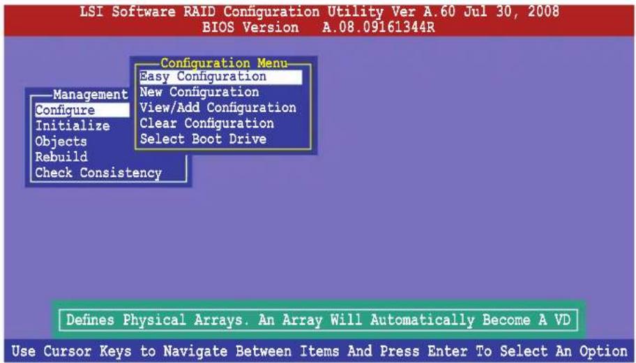
- The ARRAY SELECTION MENU displays the available drives connected to the SATA ports. Use the up/down arrow key to select the drives you want to include in the RAID set, and then press
. When selected, the drive indicator changes from READY to ONLIN A[X]-[Y], where X is the array number, and Y is the drive number.
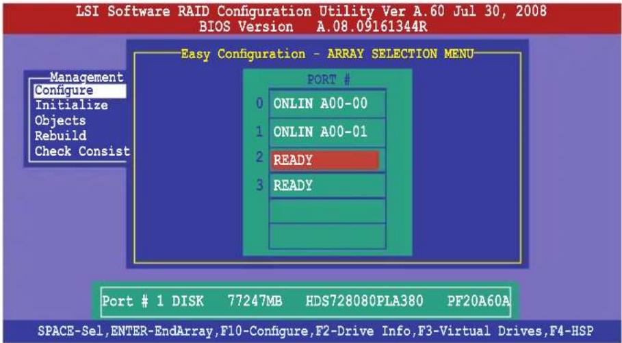

- The information of the selected hard disk drive displays at the bottom of the screen.
- You need at least two identical hard disk drives when creating a RAID 1 set.
-
You need at least four identical hard disk drives when creating a RAID 10 set.
-
Select all the drives required for the RAID set, and then press
to configure array setting. - Press
to select the configurable array.
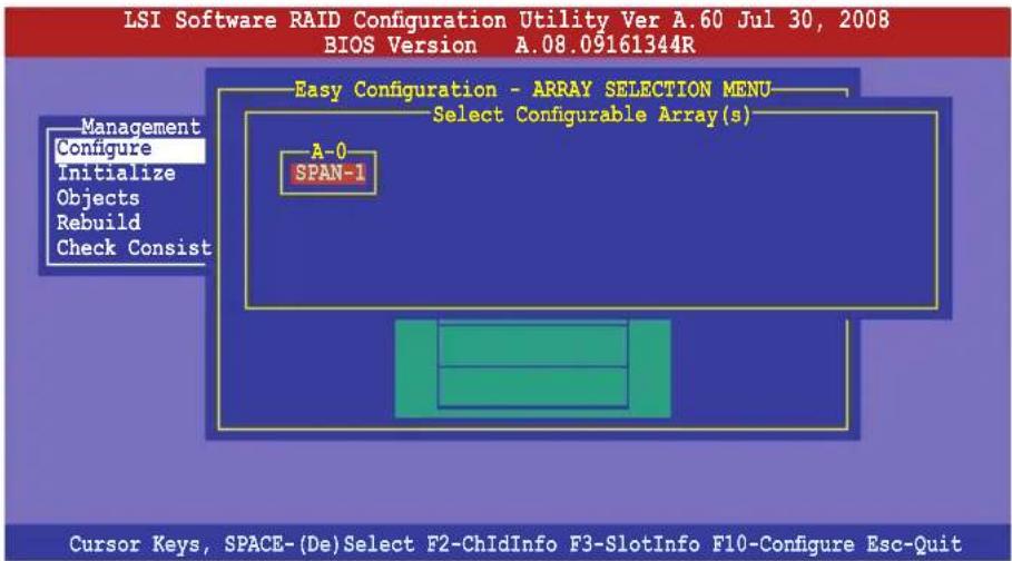
- Press
again, the virtual drive information appears including a Virtual Drive menu that allows you to change the virtual drive parameters.
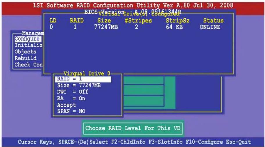
- Select RAID from the Virtual Drive sub-menu, and then press
. - Select the RAID level from the menu, and then press
.
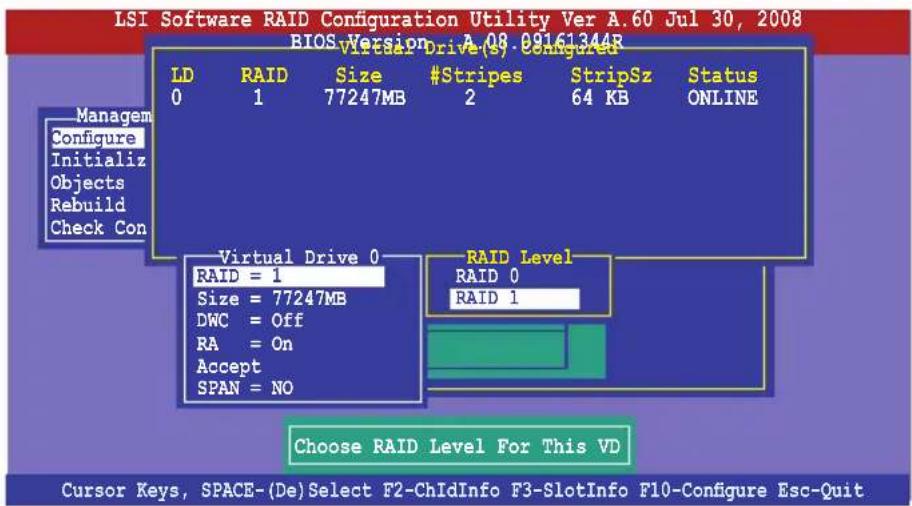
- When creating a RAID 1 or a RAID 10 set, select DWC from the Virtual Drive menu, and then press
.
When creating a RAID 0 set, proceed to step 10.
- Select On to enable the Disk Write Cache setting, and then press
.
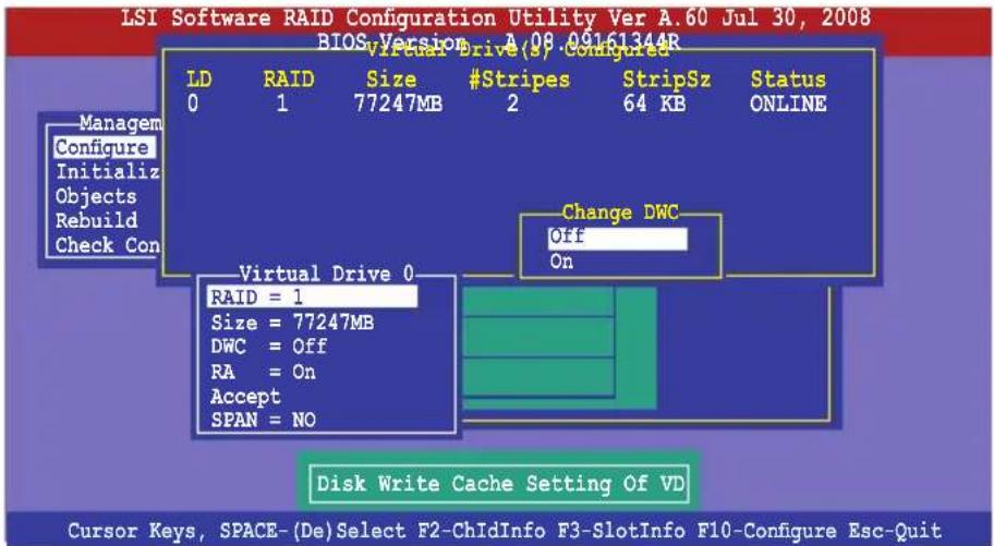

Enabling DWC can improve the performance, but with the risk of data loss.
- When finished setting the selected virtual drive configuration, select Accept from the menu, and then press
.
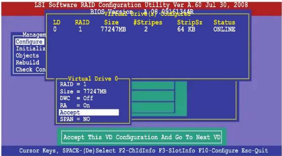
- Follow step 2 to 10 to configure additional virtual drives.
- Press
to finish RAID configuration. When prompted to save configuration, select Yes from the menu, and then press .
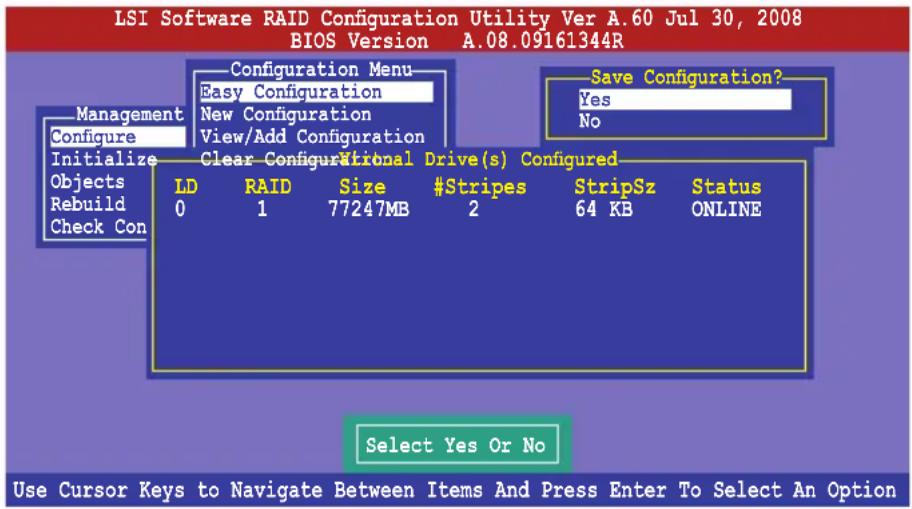
Using New Configuration

When a RAID set already exists, using the New Configuration command erases the existing RAID configuration data. If you do not want to delete the existing RAID set, use the View/Add Configuration command to view or create another RAID configuration.
To create a RAID set using the New Configuration option
- From the Management Menu, select Configure > New Configuration, and then press
.
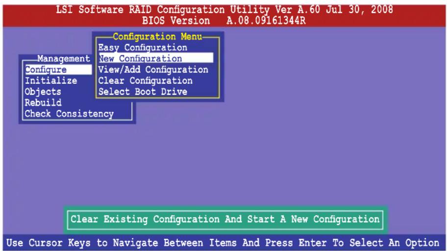
- Follow step 2 to 7 of the previous section: Using Easy Configuration.
- Select Size from the Virtual Drive menu, and then press
. - Key-in the desired virtual drive size, and then press
.

- Follow step 8 to 12 of the previous section: Using Easy Configuration to create the RAID set.
6.2.2 Adding or viewing a RAID configuration
You can add a new RAID configuration or view an existing configuration using the View/Add Configuration command.
Adding a new RAID configuration
To add a new RAID configuration:
- From the Management Menu select Configure > View/Add Configuration, and then press
.
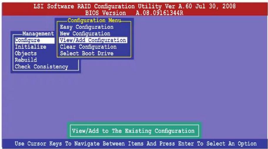
- The ARRAY SELECTION MENU displays the available drives connected to the SATA ports. Select the drive(s) you want to include in the RAID set, then press
. When selected, the drive indicator changes from READY to ONLIN A[X]-[Y], where X is the array number, and Y is the drive number.
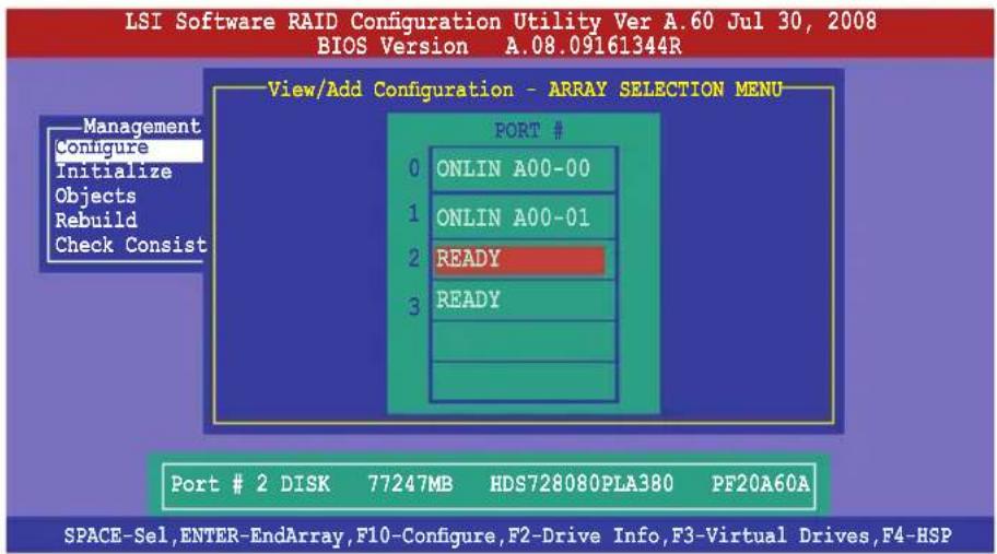

The information of the selected hard disk drive displays at the bottom of the screen.
- Follow step 3 to 12 of section 6.2.1 Creating a RAID set: Using Easy Configuration to add a new RAID set.
6.2.3 Initializing the virtual drives
After creating the RAID set(s), you must initialize the virtual drives. You may initialize the virtual drives of a RAID set(s) using the Initialize or Objects command on the Management Menu.
Using the Initialize command
To initialize the virtual drive using the Initialize command
- From the Management Menu, select Initialize, and then press
.
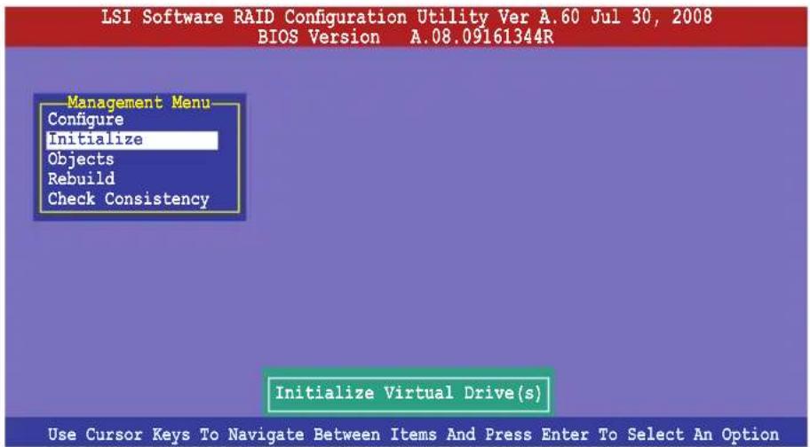
- The screen displays the available RAID set(s) and prompts you to select the virtual drive to initialize. Use the arrow keys to select the virtual drive from the Virtual Drive selection, and then press
.
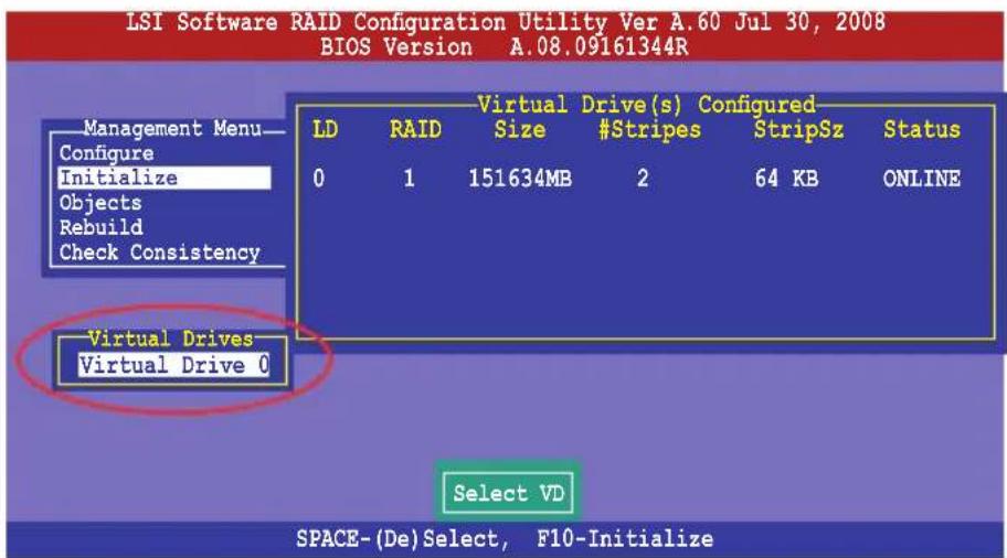
- Press
to start initialization. When prompted, select Yes from the Initialize? dialog box, and then press .
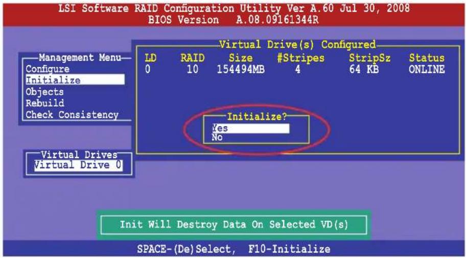

Initializing a virtual drive erases all data on the drive.
- A progress bar appears on screen. If desired, press
to abort initialization. When initialization is completed, press .
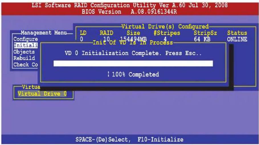
Using the Objects command
To initialize the virtual drives using the Objects command
- From the Management Menu, select Objects > Virtual Drive, and then press
.
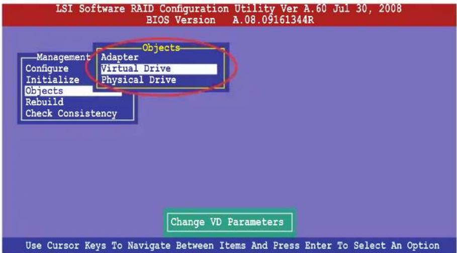
- Select the virtual drive to initialize from the then press
. Virtual Drives sub-menu, and
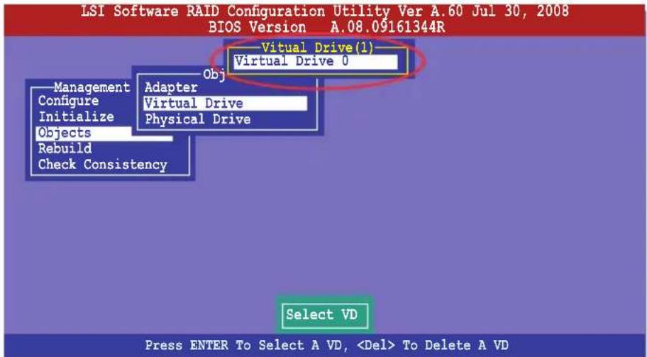
- Select Initialize from the pop-up menu, and then press
to start initialization.
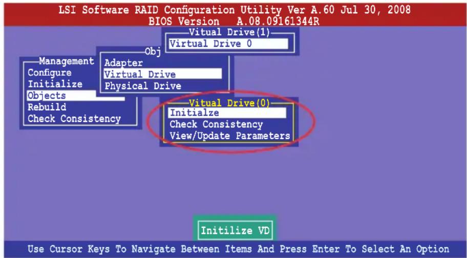
- When prompted, press the
to select Yes from the Initialize? dialog box, and then press .
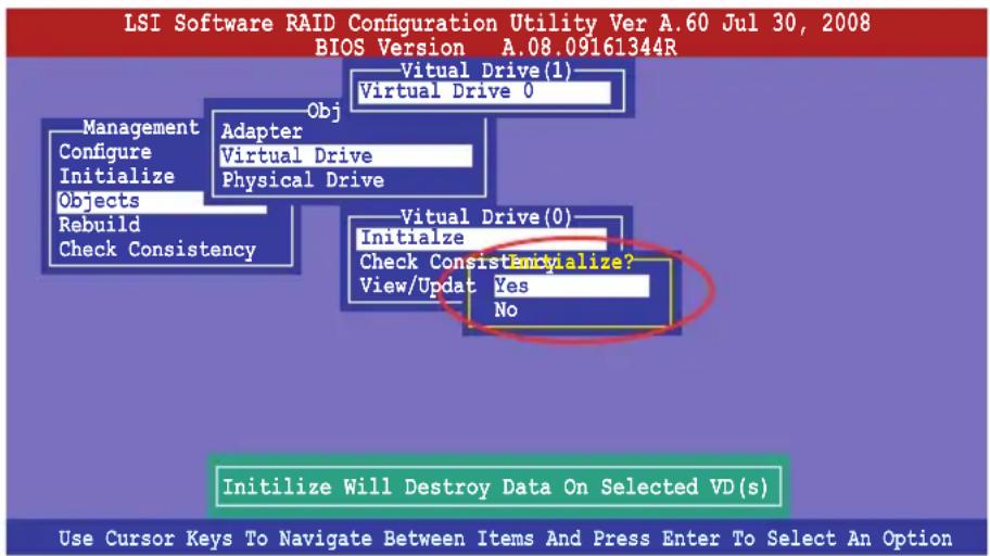
- A progress bar appears on screen. If desired, press
to abort initialization. When initialization is completed, press .
6.2.4 Rebuilding failed drives
You can manually rebuild failed hard disk drives using the Rebuild command in the Management Menu.
To rebuild a failed hard disk drive
- From the Management Menu, select Rebuild, and then press
.
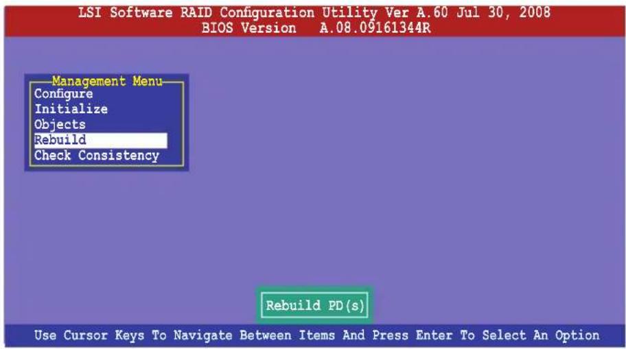
- The PHYSICAL DRIVES SELECTION MENU displays the available drives connected to the SATA ports. Select the drive you want to rebuild, and then press
.
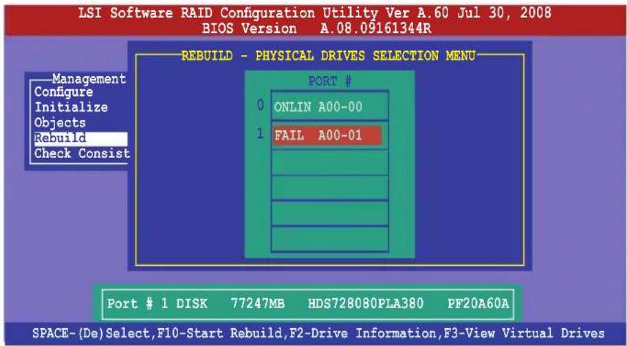
- After selecting the drive to rebuild, press
. When prompted, press to rebuild the drive.
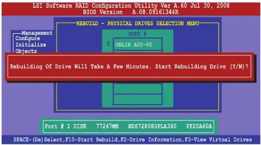
- When rebuild is complete, press any key to continue.
6.2.5 Checking the drives for data consistency
You can check and verify the accuracy of data redundancy in the selected virtual drive. The utility can automatically detect and/or detect and correct any differences in data redundancy depending on the selected option in the Objects > Adapter menu.

The Check Consistency command is available only for virtual drives included in a RAID 1 or RAID 10 set.
Using the Check Consistency Command
To check data consistency using the Check Consistency command
- From the Management Menu, select Check Consistency, and then press
.
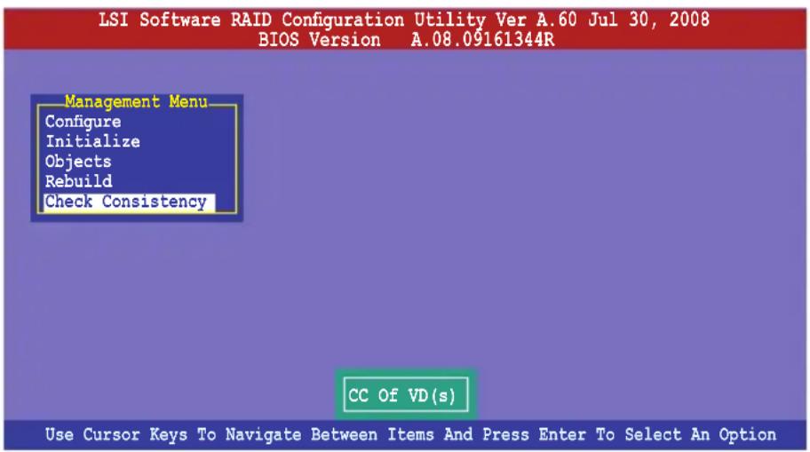
- The screen displays the available RAID set(s) and prompts you to select the virtual drive to check. Press
to select the virtual drive from the Virtual Drive sub-menu, and then press .
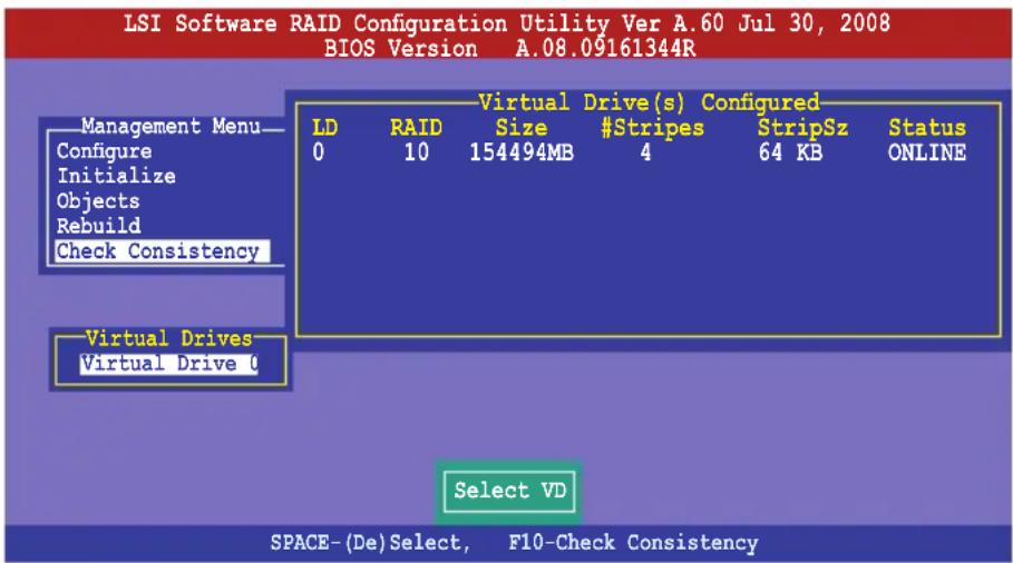
- When prompted, use the arrow keys to select Yes from the Consistency Check? dialog box, and then press
.
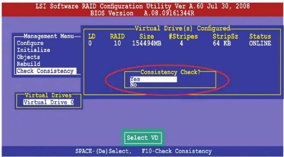
A progress bar appears on screen.
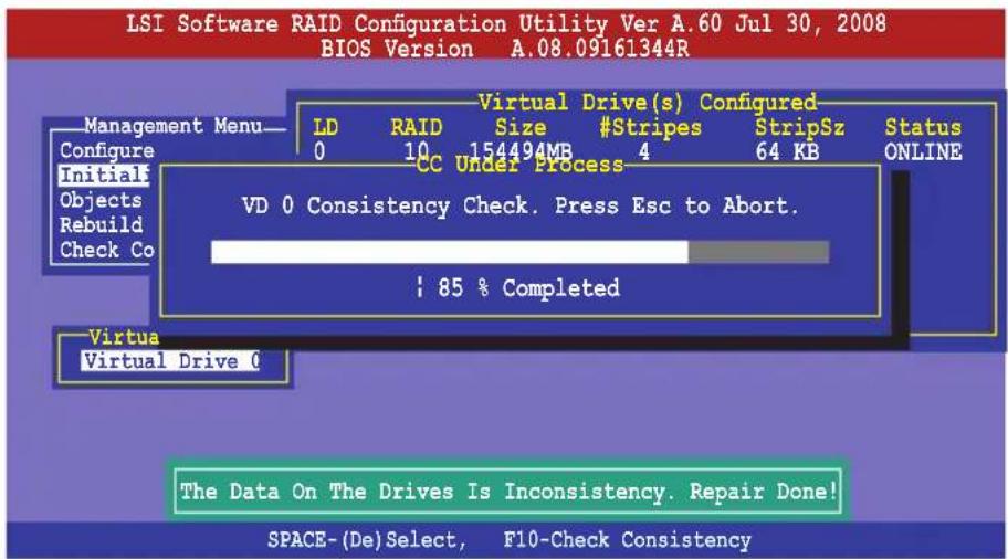
-
While checking the disk consistency, press
to display the following options. -
Stop - Stops the consistency check. The utility stores the percentage of disk checked, and when you restart checking, it continues from the last percentage completed rather than from zero percent.
- Continue - Continues the consistency check.
-
Abort - Aborts the consistency check. When you restart checking, it continues from zero percent.
-
When checking is complete, press any key to continue.
Using the Objects command
To check data consistency using the Objects command
- From the Management Menu, select Objects, and then select Virtual Drive from the sub-menu.
- Use the arrow keys to select the virtual drive you want to check, and then press
. - Select Check Consistency from the pop-up menu, and then press
. - When prompted, use the arrow keys to select Yes from the dialog box to check the drive.
- When checking is complete, press any key to continue.
6.2.6 Deleting a RAID configuration
To delete a RAID configuration
- From the Management Menu, select Configure > Clear Configuration, and then press
.
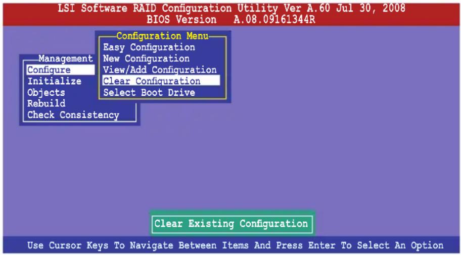
- When prompted, use the arrow keys to select Yes from the Clear Configuration? dialog box, and then press
.
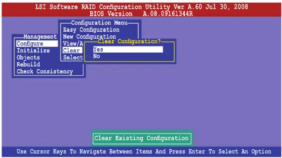
The utility clears all the current array(s).
- Press any key to continue.
6.2.7 Selecting the boot drive from a RAID set
You must have created a new RAID configuration before you can select the boot drive from a RAID set. See section 6.2.1 Creating a RAID set: Using New Configuration for details.
To select the boot drive from a RAID set
- From the Management Menu, select Configure > Select Boot Drive, and then press
.
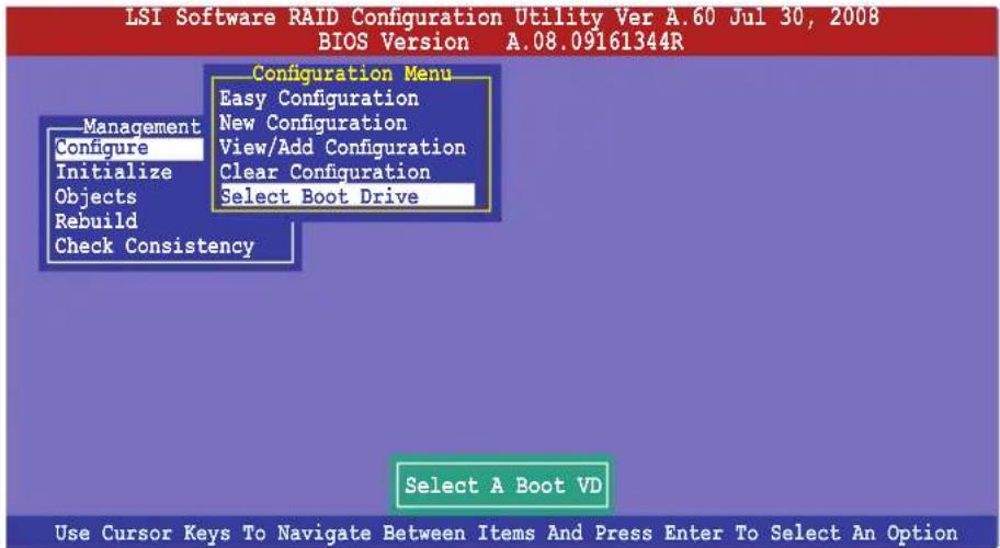
- When prompted, use the arrow keys to select the bootable virtual drive from the list, then press
.
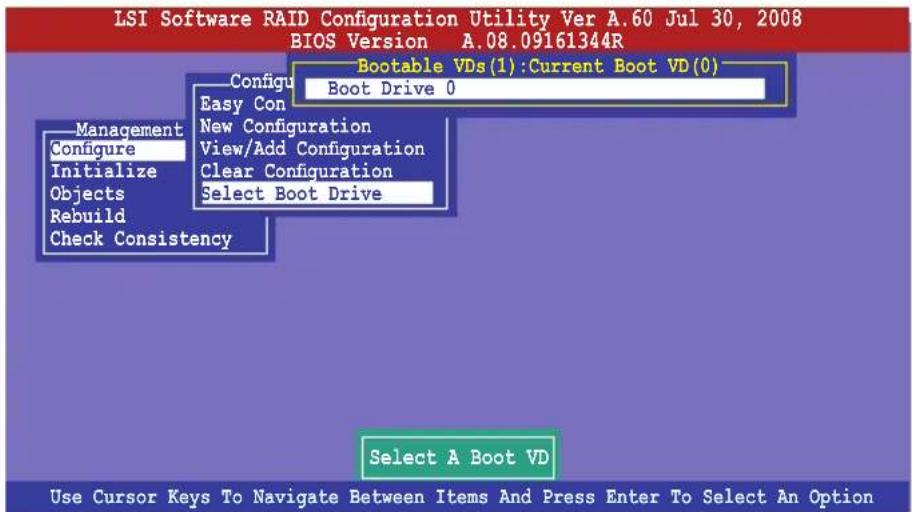
- The virtual drive is selected as boot drive. Press any key to continue.
6.2.8 Enabling WriteCache
You may manually enable the RAID controller's WriteCache option after creating a RAID set to improve the data transmission performance.

When you enable WriteCache, you may lose data when a power interruption occurs while transmitting or exchanging data among the drives.
The WriteCache function is recommended for RAID 1 and RAID 10 sets.
To enable WriteCache
- From the Management Menu, select Objects >Adapter, and then press
to display the adapter properties. - Select Disk WC, and then press
to turn on the option.
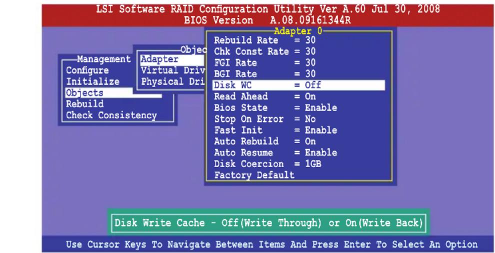
- From the Management Menu, select Objects > Virtual Drive, and then press
to display the adapter properties. - Select Disk WC, and then press
to turn on the option.
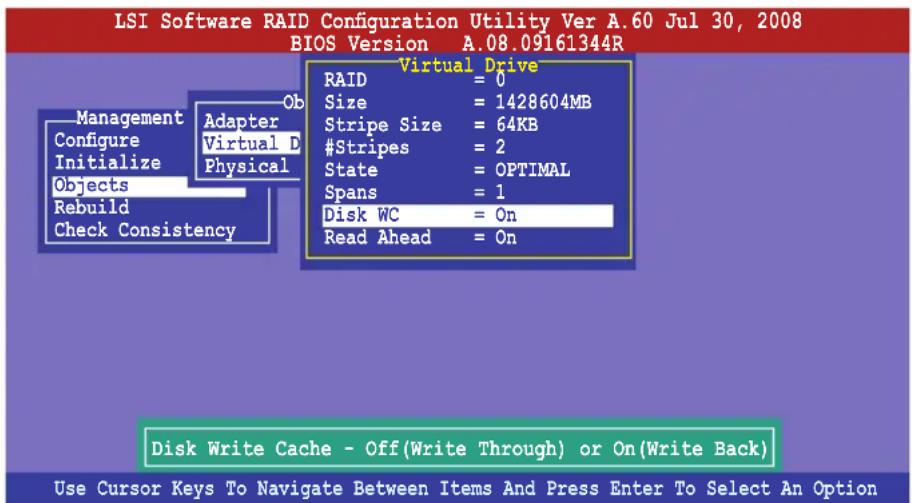
- When finished, press any key to continue.
6.3 Intel ^® Matrix Storage Manager Option ROM Utility
The Intel ^® Matrix Storage Manager Option ROM utility allows you to create RAID 0, RAID 1, RAID 10 (RAID 1+0), and RAID 5 set(s) from Serial ATA hard disk drives that are connected to the Serial ATA connectors supported by the Southbridge.
To enter the Intel ^® Matrix Storage Manager option ROM utility:
- Install all the Serial ATA hard disk drives.
- Turn on the system.
- During POST, press
![Intel(R) Matrix Storage Manager option ROM v8.5.0.1030 ICH10R/DO wRAID5 Copyright(C) 2003-08 Intel Corporation. All Rights Reserved. [ MAIN MENU ] 1. Create RAID Volume 3. Reset Disks to Non-RAID 2. Delete RAID Volume 4. Recovery Volume Options 5. Exit [ DISK/VOLUME INFORMATION ] RAID Volumes: * = Data is Encrypted None defined. Physical Disks: Port Drive Model Serial # Size Type/Status(Vol ID) 0 ST3160812AS 9LS0HJA4 149.0GB Non-RAID Disk 1 ST3160812AS 9LS0F4HL 149.0GB Non-RAID Disk 2 ST3160812AS 3LS0JYL8 149.0GB Non-RAID Disk 3 ST3160812AS 9LS0BJ5H 149.0GB Non-RAID Disk [↑↓]-Select [ESC]-Exit [ENTER]-Select Menu](/content/2026/06/1166783/images/ecca400ad28df9ff3cf1757baea0f48de5f247e1eca70d209cb5f4ae43c6fa31.jpg)
The navigation keys at the bottom of the screen allow you to move through the menus and select the menu options.

The RAID BIOS setup screens shown in this section are for reference only and may not exactly match the items on your screen.
The utility supports maximum four hard disk drives for RAID configuration.
6.3.1 Creating a RAID set
To create a RAID set
- From the utility main menu, select 1. Create RAID Volume and press
. The following screen appears.
![Intel(R) Matrix Storage Manager option ROM v8.5.0.1030 ICH10R/DO wRAID5 Copyright(C) 2003-08 Intel Corporation. All Rights Reserved. [ CREATE VOLUME MENU ] Name: Volume0 RAID Level: RAID0(Stripe) Disks: Select Disks Strip Size: 128KB Capacity: 0.0 GB Sync: N/A Create Volume [ HELP ] Enter a unique volume name that has no special characters and is 16 characters or less. [↑↓]Change [TAB]-Next [ESC]-Previous Menu [ENTER]-Select](/content/2026/06/1166783/images/5de3a305addba0ce568bc44dce56a32d121a4ba774fc78183f22bb17fed405d1.jpg)
- Enter a name for the RAID set and press
. - When the RAID Level item is selected, press the up/down arrow key to select a RAID level to create, and then press
. - When the Disks item is selected, press
to select the hard disk drives you want to include in the RAID set. The SELECT DISKS screen appears.
![[ SELECT DISKS ] Port Drive Model Serial # Size Status 0 ST3160812AS 9LS0HJA4 149.0GB Non-RAID Disk 1 ST3160812AS 9LS0F4HL 149.0GB Non-RAID Disk 2 ST3160812AS 3LS0JYL8 149.0GB Non-RAID Disk 3 ST3160812AS 9LS0BJ5H 149.0GB Non-RAID Disk Select 2 to 6 disks to use in creating the volume. [↑↓]-Prev/Next [SPACE]-SelectDisk [ENTER]-Done](/content/2026/06/1166783/images/2a6879a3e2b03c06a92f16ee84f7a34bc85d2c880ca2c2e0de7447308d7d67ea.jpg)
-
Use the up/down arrow key to select a drive, and then press
to select. A small triangle marks the selected drive. Press after completing your selection. -
Use the up/down arrow key to select the stripe size for the RAID array (for RAID 0, 10 and 5 only), and then press
. The available stripe size values range from 4 KB to 128 KB. The following are typical values:
RAID 0: 128KB
RAID 10: 64KB
RAID 5: 64KB

We recommend a lower stripe size for server systems, and a higher stripe size for multimedia computer systems used mainly for audio and video editing.
- When the Capacity item is selected, enter the RAID volume capacity that you want and press
. The default value indicates the maximum allowed capacity. - When the Create Volume item is selected, press
. The following warning message appears.
WARNING: ALL DATA ON SELECTED DISKS WILL BE LOST.
Are you sure you want to create this volume? (Y/N):
- Press
to create the RAID volume and return to the main menu, or to go back to the CREATE VOLUME menu.
6.3.2 Creating a Recovery set
To create a recovery set
- From the utility main menu, select 1. Create RAID Volume and press
. The following screen appears.
![Intel(R) Matrix Storage Manager option ROM v8.5.0.1030 ICH10R/DO wRAID5 Copyright(C) 2003-08 Intel Corporation. All Rights Reserved. [ CREATE VOLUME MENU ] Name: Volume0 RAID Level: RAID0(Stripe) Disks: Select Disks Strip Size: 128KB Capacity: 0.0 GB Sync: N/A Create Volume [ HELP ] Enter a unique volume name that has no special characters and is 16 characters or less. [↑↓]Change [TAB]-Next [ESC]-Previous Menu [ENTER]-Select](/content/2026/06/1166783/images/e9af665da35b4888eed8be6dc524b5bfa04a0ae552f8a83178fd629746647f3c.jpg)
- Enter a name for the recovery set and press
. - When the RAID Level item is selected, press the up/down arrow key to select Recovery, and then press
. - When the Disks item is selected, press
to select the hard disk drives you want to include in the recovery set. The SELECT DISKS screen appears.
![[ SELECT DISKS ] Port Drive Model Serial # Size Status 0 ST3160812AS 9LS0HJA4 149.0GB Non-RAID Disk 1 ST3160812AS 9LS0F4HL 149.0GB Non-RAID Disk 2 ST3160812AS 3LS0JYL8 149.0GB Non-RAID Disk 3 ST3160812AS 9LS0BJ5H 149.0GB Non-RAID Disk Select 1 Master and 1 Recovery disk to create volume. [↑↓] -Prev/Next [TAB] - (M) aster [SPACE] - (R) recovery [ENTER] -Done](/content/2026/06/1166783/images/620fe974870ba80519b2efdd1b733d961aaf83cdc4d9c8f4010ef21e05f35f3a.jpg)
- Use the up/down arrow key to select a drive, press
to select a Master disk, and then press to select a Recovery disk. A small triangle marks the selected drive. Press after completing your selection. - When the Sync item is selected, use the up/down arrow key to select a sync option that you want and press
. - When the Create Volume item is selected, press
. The following warning message appears.

- Press
to create the recovery set and return to the main menu, or to go back to the CREATE VOLUME menu.

If a recovery set is created, you cannot add more RAID sets even when you have more non-RAID disks installed in your system.
6.3.3 Deleting a RAID set

Take caution when deleting a RAID set. You will lose all data on the hard disk drives when you delete a RAID set.
To delete a RAID set
- From the utility main menu, select 2. Delete RAID Volume and press
. The following screen appears.
![Intel(R) Matrix Storage Manager option ROM v8.5.0.1030 ICH10R/DO wRAID5 Copyright(C) 2003-08 Intel Corporation. All Rights Reserved. [ DELETE VOLUME MENU ] Name Level Drives Capacity Status Bootable Volume0 RAID0(Stripe) 2 298.0GB Normal Yes [ HELP ] Deleting a volume will reset the disks to non-RAID. WARNING: ALL DISK DATA WILL BE DELETED. (This does not apply to Recovery volumes) [↑↓]-Select [ESC]-Previous Menu [DEL]-Delete Volume](/content/2026/06/1166783/images/4aa558ca6b2975a48df0fa09d57f13d0977aa49569374b7c60ecd8aa3d2f7243.jpg)
- Use the up/down arrow key to select the RAID set you want to delete, and then press
. The following warning message appears.
![[ DELETE VOLUME VERIFICATION ] ALL DATA IN THE VOLUME WILL BE LOST! (This does not apply to Recovery volumes) Are you sure you want to delete volume "Volume0"? (Y/N):](/content/2026/06/1166783/images/b0db388baa79fb3fcd9554b68dc0936517060047ab9d650648d1a763b6c84f10.jpg)
- Press
to delete the RAID set and return to the utility main menu, or press to return to the DELETE VOLUME menu.
6.3.4 Resetting disks to Non-RAID

Take caution before you reset a RAID volume hard disk drive to non-RAID. Resetting a RAID volume hard disk drive deletes all internal RAID structure on the drive.
To reset a RAID set hard disk drive
- From the utility main menu, select 3. Reset Disks to Non-RAID and press
. The following screen appears.
![[ RESET RAID DATA ] Resetting RAID disk will remove its RAID structures and revert it to a non-RAID disk. WARNING: Resetting a disk causes all data on the disk to be lost. (This does not apply to Recovery volumes) Port Drive Model Serial # Size Status 0 ST3160812AS 9LS0HJA4 149.0GB Member Disk 1 ST3160812AS 9LS0F4HL 149.0GB Member Disk Select the disks that should be reset. [↑↓] -Previous/Next [SPACE]-Selects [ENTER]-Selection Complete](/content/2026/06/1166783/images/cb1a564ca79aa25fc594fb7870cdfc4e5e3c72926584ee7a73bcf243eb26d9f2.jpg)
- Use the up/down arrow key to select the RAID set drive(s) you want to reset, and then press
to select. - Press
to reset the RAID set drive(s). A confirmation message appears. - Press
to reset the drive(s) or press to return to the utility main menu.
6.3.5 Recovery Volume Options
If you have created a recovery set, you can configure more recovery set options following the descriptions in the section.

See section 6.3.2 Creating a Recovery set to create a recovery set before continue.
To configure a recovery set
- From the utility main menu, select 4. Recovery Volume Options and press
. The following screen appears.
![Intel(R) Matrix Storage Manager option ROM v8.5.0.1030 ICH10R/DO wRAID5 Copyright(C) 2003-08 Intel Corporation. All Rights Reserved. [ RECOVERY VOLUME OPTIONS ] 1. Enable Only Recovery Disk 2. Enable Only Master Disk [ HELP ] Enable Only Recovery Disk - enables recovery disk if available and disables master disk. Enable Only Master Disk - enables master disk if available and disables recovery disk. Actions will result in change from Continuous Update mode to On-Request. [↑↓]-Select [ESC]-Previous Menu [ENTER]-Select](/content/2026/06/1166783/images/cd1c451c4e2d3f44621c6c7740a34ef961a29aeea59bf8315ba5e5480124d340.jpg)
- Use the up/down arrow key to select the option you want, and then press
. The SELECT RECOVERY VOLUME screen appears.
![[ SELECT RECOVERY VOLUME ] Name Level Capacity Status Bootable Volume0 Recovery (Cont.) 149.0GB Normal Yes Select a Recovery volume to do the operation. [↑↓]-Up/Down [SPACE]-Selects [ENTER]-Done](/content/2026/06/1166783/images/a4a941954f05452e2757a7000914410382e0015d4df88972c75855ba19ef8a8b.jpg)
- Use the up/down arrow key to select a drive, and then press
to select. A small triangle marks the selected drive. Press after completing your selection and return to the utility main menu.
6.3.6 Exiting the Intel ^® Matrix Storage Manager
To exit the utility
- From the utility main menu, select 5. Exit, and then press
. The following warning message appears.
![[ CONFIRM EXIT ] Are you sure you want to exit? (Y/N):](/content/2026/06/1166783/images/05880073cc4c53f7feaff1b2f7f0a7a66bba7f18342de95d87c429dfee57b4de.jpg)
- Press
to exit or press to return to the utility main menu.
6.3.7 Rebuilding the RAID

This option is only for the RAID 1 set.
Rebuilding the RAID with other non-RAID disk
If any of the SATA hard disk drives included in the RAID 1 array failed, the system displays the status of the RAID volume as "Degraded" during POST. You can rebuild the RAID array with other installed non-RAID disks.
To rebuild the RAID with other non-RAID disk:
- At the prompt, press
+ to enter the Intel Matrix Storage Manager option ROM utility. - If there is a non-RAID SATA Hard Disk available, the utility will prompt to rebuild the RAID. Press
, and then use up/down arrow keys to select the destination disk or press to exit.
![[ DEGRADED VOLUME DETECTED ] "Degraded" volume and disk available for rebuilding detected. Selecting a disk initiates a rebuild. Rebuild completes in the operating system. Select the port of destination disk for rebuilding (ESC to exit): Port Drive Model Serial # Size XXXXXXXXXXX XXXXXXXX XX.XGB [↑↓]-Previous/Next [ENTER]-Select [ESC]-Exit](/content/2026/06/1166783/images/60acd9b82eb2bab57e31393e45de2ee2e6ed4e2c9426b0c3625ed016aca34535.jpg)

Select a destination disk with the same size as the original hard disk.
- The utility immediately starts rebuilding after the disk is selected. The status of the degraded RAID volume is changed to "Rebuild".
![Intel(R) Matrix Storage Manager option ROM v8.5.0.1030 ICH10R/DO wRAID5 Copyright(C) 2003-08 Intel Corporation. All Rights Reserved. [ MAIN MENU ] 1. Create RAID Volume 2. Delete RAID Volume 3. Reset Disks to Non-RAID 4. Recovery Volume Options 5. Exit [ DISK/VOLUME INFORMATION ] RAID Volumes: ID Name Level Strip Size Status Bootable 0 Volume0 RAID1 (Mirror) N/A 149.0GB Rebuild Yes Physical Disks: Port Drive Model Serial # 1 ST3160812AS 9LS0F4HL 2 ST3160812AS 3LS0JYL8 Size Type/Status(Vol ID) 149.0GB Member Disk(0) 149.0GB Member Disk(0) Volumes with "Rebuild" status will be rebuilt within the operating system. [↑↓]-Select [ESC]-Exit [ENTER]-Select Menu](/content/2026/06/1166783/images/9a786d1a1967624e85a5b7b24948e5551ef99361f97338bce8ef56e6258c20f4.jpg)
- Exit Intel Matrix Storage Manager and reboot the system.
- Select Start > Programs > Intel Matrix Storage > Intel Matrix Storage Console or click the Intel Matrix Storage Manager tray icon to load the Intel Matrix Stroage Manager utility.
- From the View menu, select Advanced Mode to display the details of the Intel Matrix Storage Console.
- From the Volumes view option, select RAID volume to view the rebuilding status. When finished, the status is changed to "Normal".
Rebuilding the RAID with a new hard disk
If any of the SATA hard disk drives included in the RAID array failed, the system displays the status of the RAID volume as "Degraded" during POST. You may replace the disk drive and rebuild the RAID array.
To rebuild the RAID with a new hard disk:
- Remove the failed SATA hard disk and install a new SATA hard disk of the same specification into the same SATA Port.

Select a destination disk with the same size as the original hard disk.
- Reboot the system and then follow the steps in section Rebuilding the RAID with other non-RAID disk on page 6-31.
6.3.8 Setting the Boot array in the BIOS Setup Utility
You can set the boot priority sequence in the BIOS for your RAID arrays when creating multi-RAID using the Intel® Matrix Storage Manager.
To set the boot array in the BIOS:

Set at least one of the arrays bootable to boot from the hard disk.
- Reboot the system and press
to enter the BIOS setup utility during POST. - Go to the Boot menu and select the option Boot Device Priority.
- Use up/down arrow keys to select the boot priority and press
. See section 5.6.1 Boot Device Priority for details. - From the Exit menu, select Exit & Save Changes, then press
. - When the confirmation window appears, select OK, then press
.
Chapter 7
This chapter provides instructions for installing the necessary drivers for different system components.
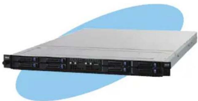
natural_image
Front view of a server rack with multiple drive bays and indicator lights (no visible text or labels)7.1 RAID driver installation
After creating the RAID sets for your server system, you are now ready to install an operating system to the independent hard disk drive or bootable array. This part provides instructions on how to install the RAID controller drivers during OS installation.
7.1.1 Creating a RAID driver disk

The system does not include a floppy drive. You have to use a USB floppy drive when creating a SATA RAID driver disk.

If you have created RAID sets with the LSI Software RAID configuration utility, the boot priority of the SATA optical disk drive has to be manually adjusted. Otherwise, the system will not boot from the connected SATA ODD.
A floppy disk with the RAID driver is required when installing Windows ^® or Red Hat ^® Enterprise operating system on a hard disk drive that is included in a RAID set. You can create a RAID driver disk in DOS (using the Makedisk application in the support DVD).
To create a RAID driver disk in DOS environment
- Place the motherboard support DVD in the optical drive.
- Restart the computer, and then enter the BIOS Setup.
- Select the optical drive as the first boot priority to boot from the support DVD. Save your changes, and then exit the BIOS Setup.
- Restart the computer. The Makedisk menu appears.
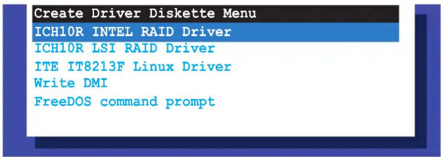
- Use the arrow keys to select the type of RAID driver disk you want to create and press
to enter the sub-menu.
ICH10R INTEL RAID Driver
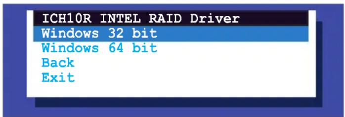
ICH10R LSI RAID Driver
| ICH10R LSI RAID Driver |
| Windows XP 32 bit |
| Windows XP 64 bit |
| Windows Server 2003 32 bit |
| Windows Server 2008 64 bit |
| Windows Vista 32 bit |
| Windows Vista 64 bit |
| Windows Server 2008 32 bit |
| Windows Server 2008 64 bit |
| RHEL AS4 UP6 32/64 bit |
| RHEL AS4 UP7 32/64 bit |
| RHEL 5 UP1 32/64 bit |
| RHEL 5 UP2 32/64 bit |
| SLES 9 SP3 32 bit |
| SLES 9 SP3 64 bit |
| SLES 9 SP4 32 bit |
| SLES 9 SP4 64 bit |
| SLES 10 SP1 32 bit |
| SLES 10 SP1 64 bit |
| SLES 10 SP2 32 bit |
| SLES 10 SP2 64 bit |
| Back |
| Exit |
- Locate the RAID driver and place a blank, high-density floppy disk to the floppy disk drive.
- Press
. - Follow screen instructions to create the driver disk.
To create a RAID driver disk in Windows ^® environment
- Start Windows ^® .
- Place the motherboard support DVD into the optical drive.
- Go to the Make Disk menu, and then select the type of RAID driver disk you want to create.
- Insert a floppy disk into the floppy disk drive.
- Follow succeeding screen instructions to complete the process.

Write-protect the floppy disk to avoid computer virus infection.
To create a RAID driver disk in Red Hat® Enterprise Linux server environment
- Insert a blank formatted high-density floppy disk to the floppy disk drive.
- Type dd if=XXX.img of=/dev/fd0 to decompress the file into the floppy disk from the following path in the support DVD:
For LSI MegaRAID Driver
\Drivers\ICH10R LSI RAID\Driver\makedisk/Linux
- Eject the floppy disk.
7.1.2 Installing the RAID controller driver
Windows® Server OS
During Windows ^® Server OS installation
To install the RAID controller driver when installing Windows ^® Server OS:
- Boot the computer using the Windows ^ Server installation DVD. The Windows ^ Server OS Setup starts.
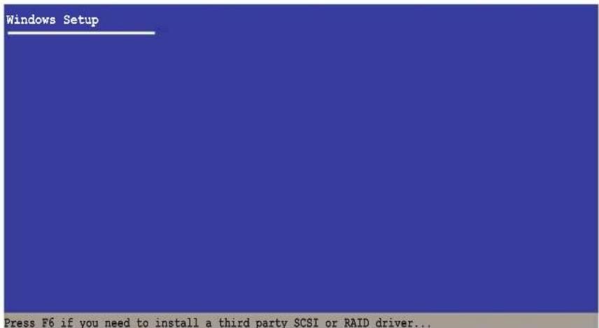
- Press
when the message "Press F6 if you need to install a third party SCSI or RAID driver..." appears at the bottom of the screen. - When prompted, press
to specify an additional device.
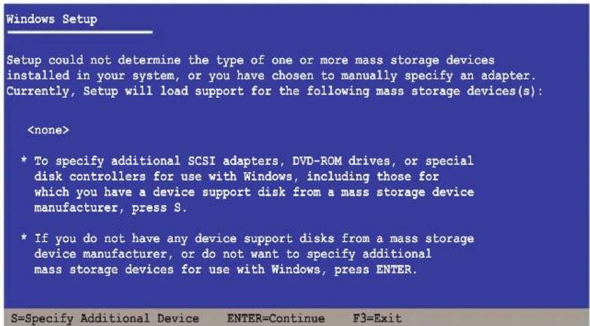
- Insert the RAID driver disk you created earlier to the floppy disk drive, then press
.
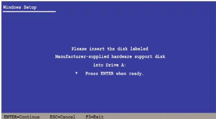
- Select the RAID controller driver you need from the list, then press
. - The Windows ^ Setup loads the RAID controller drivers from the RAID driver disk. When prompted, press
to continue installation. - Setup then proceeds with the OS installation. Follow screen instructions to continue.
To an existing Windows ^® Server OS
To install the RAID controller driver on an existing Windows ^® Server OS
- Restart the computer, and then log in with Administrator privileges.
- Windows ^® automatically detects the RAID controller and displays a New Hardware Found window. Click Cancel.
- Right-click the My Computer icon on the Windows ^® desktop, and then select Properties from the menu.
- Click the Hardware tab, and then click the Device Manager button to display the list of devices installed in the system.
- Right-click the RAID controller item, then select Properties.
- Click the Driver tab, and then click the Update Driver button.
- The Upgrade Device Driver Wizard window appears. Click Next.
- Insert the RAID driver disk you created earlier to the floppy disk drive.
- Select the option Install the software automatically (Recommended), and then click Next.
- The wizard searches the RAID controller drivers. When found, click Next to install the drivers.
- Click Finish after the driver installation is done.
To verify the RAID controller driver installation:
- Right-click the My Computer icon on the Windows® desktop, and then select Properties from the menu.
- Click the Hardware tab, and then click the Device Manager button.
- Click the “+” sign before the item SCSI and RAID controllers, and then the Intel(R) ICH8R/ICH9R/ICH10R/DO SATA RAID Controller item should appear.
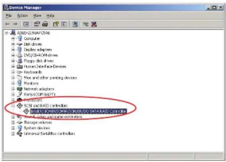

The screen differs based on the controller.
- Right-click the RAID controller driver item, and then select Properties from the menu.
- Click the Driver tab, and then click the Driver Details button to display the RAID controller drivers.
- Click OK when finished.
Red Hat® Enterprise Linux OS 4.7/4.8
To install the RAID controller driver when installing Red Hat® Enterprise OS:
- Boot the system from the Red Hat ^ OS installation CD.
- At the boot:, type linux dd nostorage.
- Press
.
- To install or upgrade in graphical mode, press the <ENTER> key.
- To install or upgrade in text mode, type: linux text <ENTER>.
- Use the function keys listed below for more information.
[F1-Main] [F2-Options] [F3-General] [F4-Kernel] [F5-Rescue]
boot: linux dd nostorage
- Select Yes using the
key when asked if you have the driver disk, then press .
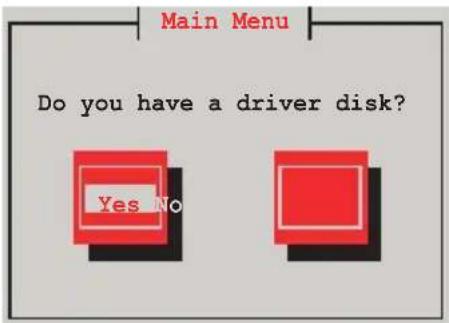
- Press
to continue.
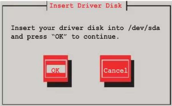
- Select No and press
to continue.
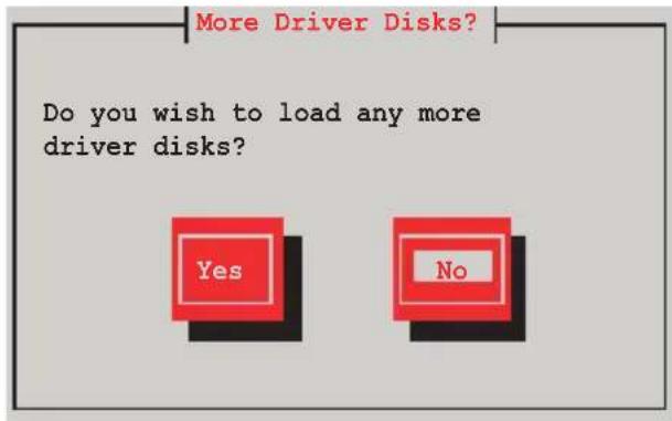
- Select your desired language and press
to continue.

- Select your keyboard type and press
to continue.
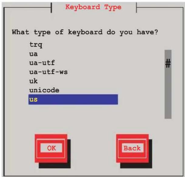
- Select the media and press
to select OK. Press to continue.
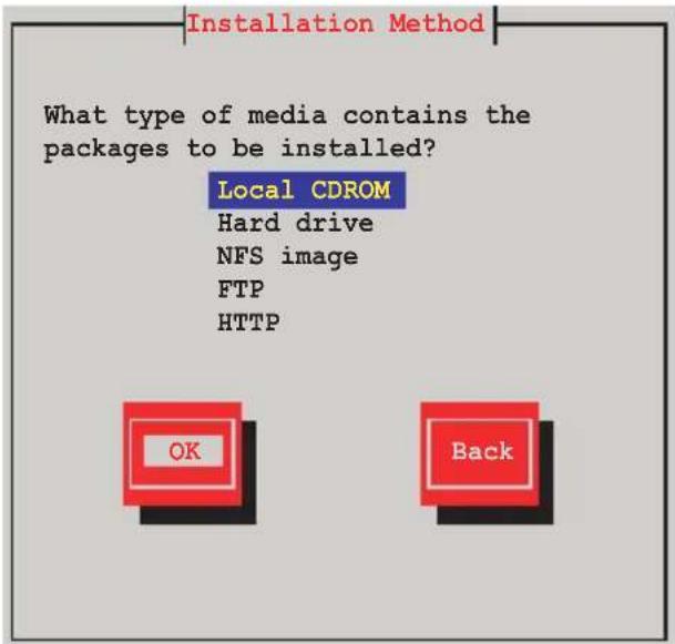
- Select the media and press
to select OK. Press to continue.
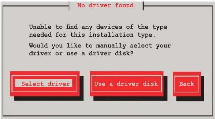
- Scroll down to locate the driver and press
to continue.
![Select Device Driver to Load Please select the driver below which you wish to load. If it does not appear and you have a driver disk, press F2. LSI Logic Fusion MPT SPI Driver (mptspi) LSI MegaRAID Controllers (megaraid_mbox) LSI MegaRAID Controllers (megaraid_sas) LSI megasr Driver ver 13.10.0708.2009 (megasr) Marvell SATA controllers (sata_mv) Mylex DAC960 RAID Controller (DAC960) [ ] Specify optional module arguments OK Back](/content/2026/06/1166783/images/d78649665ef0eb27cce4e24786b4f3ff0596085f10cab1db7c0473dbce53959c.jpg)

The driver version may vary with time and model. Select LSI Mega Software RAID driver (LSI megasr Driver) all the time.
- Select Skip and press
to continue.
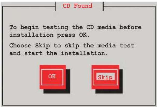
- Select Done and press
to continue.
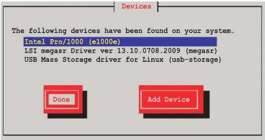

The displayed devices may vary with models and systems.
- Follow the onscreen instructions to finish installing the RedHat operating system.
Red Hat® Enterprise Linux OS 5.0
To install the RAID controller driver when installing Red Hat® RedHatise OS:
- Boot the system from the Red Hat ^® OS installation CD.
- At the boot:, type linux dd noprobe=ata [n]. The number of ata varies with the hard disk drive number you have when building a RAID set. For example, if you want to build a RAID set with 6 hard disk drives, type command line: linux dd noprobe=ata1 noprobe=ata2 noprobe=ata3 noprobe=ata4 noprobe=ata5 noprobe=ata6.
- Press
.
- To install or upgrade in graphical mode, press the <ENTER> key.
- To install or upgrade in text mode, type: linux text <ENTER>.
- Use the function keys listed below for more information.
[F1-Main] [F2-Options] [F3-General] [F4-Kernel] [F5-Rescue]
boot: linux dd noprobe=ata[n]
- Select Yes using the
key when asked if you have the driver disk, then press .
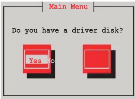
- Select fd0 using the
key when asked to select the driver disk source. Press to move the cursor to OK, then press .
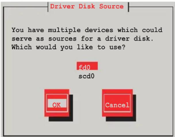
- Insert the Red Hat ^ Enterprise RAID driver disk to the floppy disk drive, select OK, then press
.
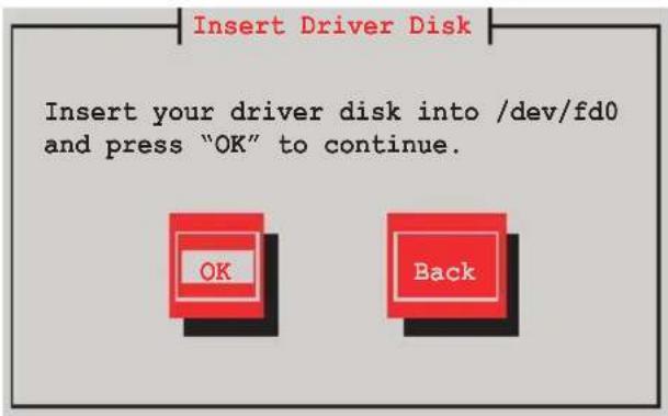
The drivers for the RAID card are installed to the system.
- When asked if you will load additional RAID controller drivers, select No, then press
.
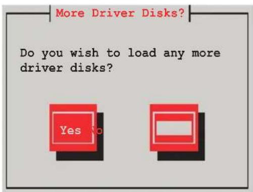
-
Follow the onscreen instructions to finish the OS installation.
-
If you install RHEL AS5, when the installation is completed, DO NOT click Reboot. Press
+ + to switch to the command-line interface from graphic user interface. -
Type the following commands when using a USB floppy.
cat /proc/partitions
Write down the Major and Minor number before sdb for later use.
mknod /dev/sdb b [major number] [minor number]
mkdir /mnt/driver
mount /dev/sdb /mnt/driver
cd /mnt/driver
sh replace_ahci.sh
reboot
SUSE Linux OS
To install the RAID controller driver when installing SUSE Linux Enterprise Server SUSE Linux E OS
- Boot the system from the SUSE OS installation CD.
- Use the arrow keys to select Installation from the Boot Options menu.
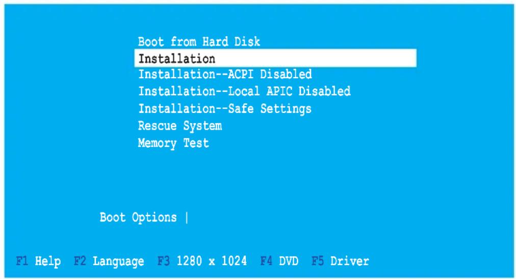
- Press
, then select Yes from the menu. Press .
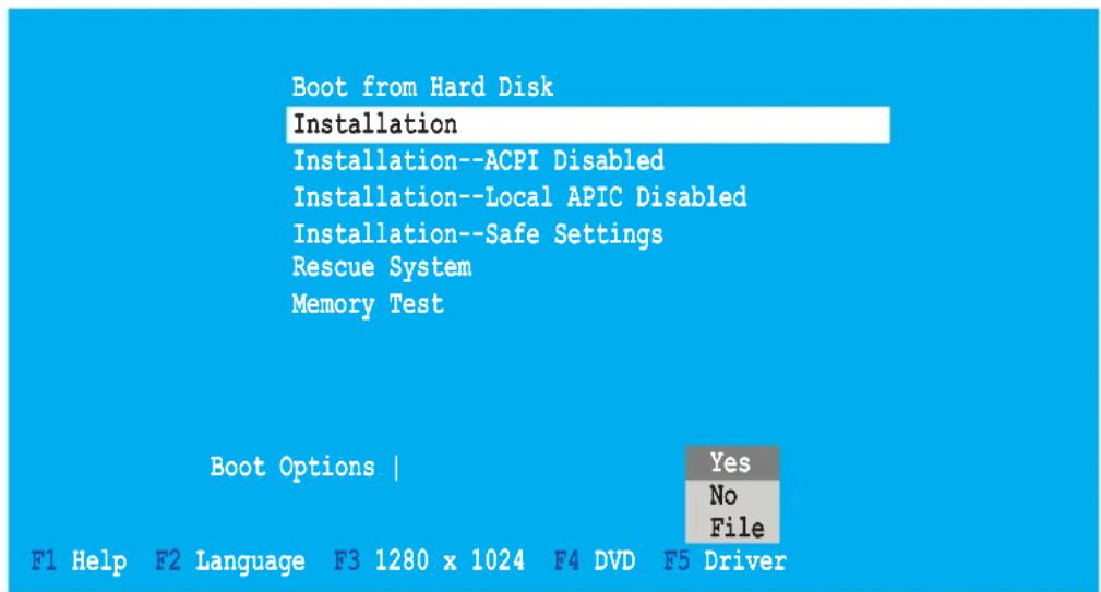
- Insert the RAID driver disk to the floppy disk drive. Make sure that Installation from the Boot Options menu is selected, then press
.
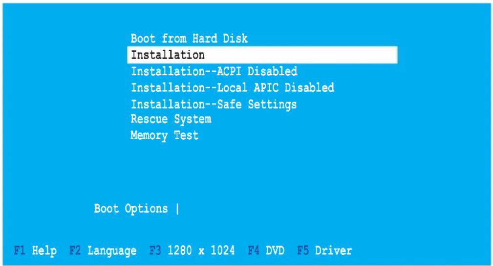

If you install SLES 10, type brokenmodules=ahci after Boot Options and press Enter to continue.
- When below screen appears, select the floppy disk drive (fd0) as the driver update medium. Select OK, then press
.
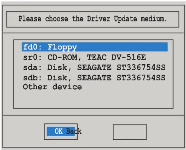
The drivers for the RAID controller are installed to the system.
7.2 Intel ^® chipset device installation
This section provides instructions on how to install the Plug and Play components for the Intel ^® chipset on the system.
You need to manually install the Intel ^® chipset software on a Windows Server operating system. To install the Intel ^® chipset device software:
- Restart the computer, then log on with Administrator privileges.
- Insert the motherboard/system support DVD to the optical drive. The support DVD automatically displays the Drivers menu if Autorun is enabled in your computer.
- Click the item Intel Chipset Device Software from the menu.
- The Intel(R) Chipset Device Software window appears. Click Next to start installation.
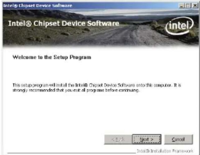
- Select Yes to accept the terms of the License Agreement and continue the process.
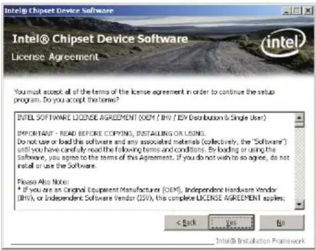
- Read the Readme File Information and press Next to continue the installation.
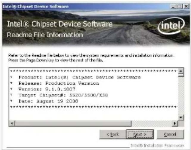
- After completing the installation, click Finish to complete the setup process.
7.3 LAN driver installation
This section provides instructions on how to install the Intel ^® Gigabit LAN controller drivers on a Windows ^® Server OS.
To install the LAN controller drivers
- Restart the computer, and then log on with Administrator privileges.
- Insert the motherboard/system support DVD to the optical drive. The DVD automatically displays the Drivers menu if Autorun is enabled in your computer.

- Windows ^® automatically detects the LAN controllers and displays a New Hardware Found window. Click Cancel to close this window.
-
If Autorun is NOT enabled in your computer, browse the contents of the support DVD to locate the file ASSETUP.EXE from the BIN folder. Double-click the ASSETUP.EXE to run the DVD.
-
Click the Intel Network Connections Software to begin installation.
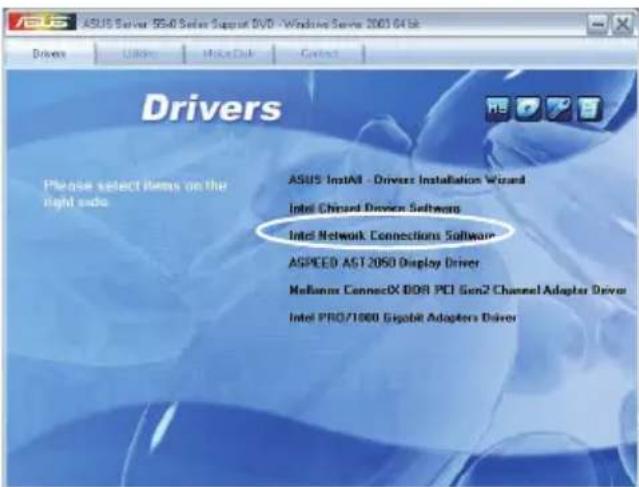
- Click Install Drivers and Software option to begin installation.
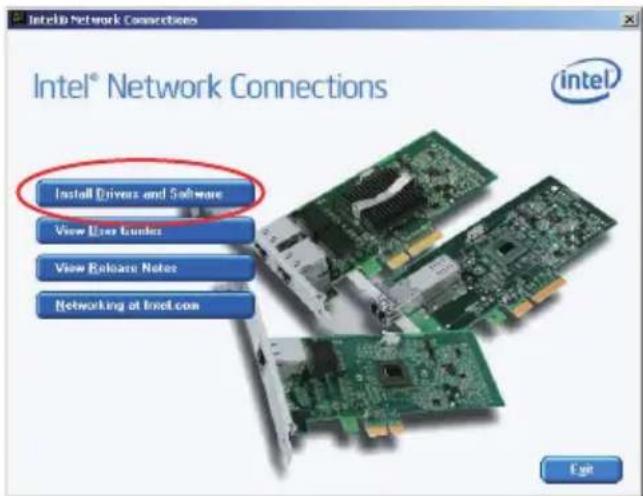
- Click Next when the Intel(R) Network Connections—InstallShield Wizard window appears.
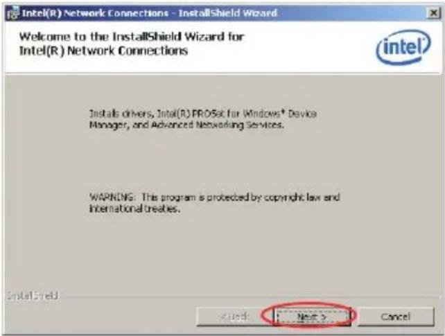
- Toggle I accept the terms in the license agreement and click Next to continue.
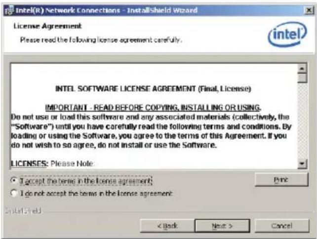
- Click the Intel(R) PROSet for Windows Device Manager box, and then click Next to start the installation.
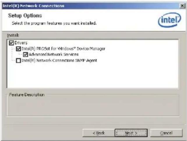
- Follow the screen instructions to complete installation.
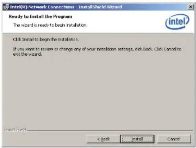
- When finished, press Finish to continue.
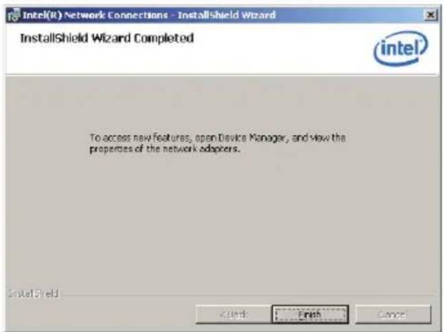
7.4 VGA driver installation
This section provides instructions on how to install the Aspeed ^® Video Graphics Adapter (VGA) driver.
You need to manually install the Aspeed ^® VGA driver on a Windows ^® Server operating system.
To install the Aspeed® VGA driver
- Restart the computer, then log on with Administrator privileges.
- Insert the motherboard/system support DVD to the optical drive. The support DVD automatically displays the Drivers menu if Autorun is enabled in your computer.
- Click Next to start the installation.
- Click Install to update the VGA driver.
- When the installation completes, click Finish to restart your computer before using the program.
7.5 Mellanox ConnectX DDR PCI Gen2 Channel Adapter driver installation (For RS702D-E6/PS8; RS704D-E6/PS8)
This section provides instructions on how to install the Mellanox driver.
7.5.1 Windows operating system
You need to manually install the Mellanox driver on a Windows® operating system.
To install the Mellanox driver
- Restart the computer, then log on with Administrator privileges.
- Insert the motherboard/system support DVD to the optical drive. The support DVD automatically displays the Drivers menu if Autorun is enabled in your computer.
- Click Mellanox ConnectX DDR PCI Gen2 Channel Adapter Driver.
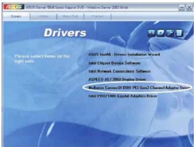
- Click Next to start installing the driver.
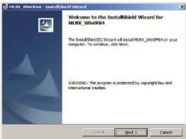
- Click I accept the terms in the license agreement and click Next to continue.
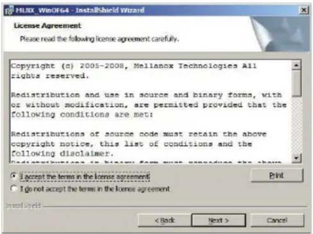
- Click Change to select your desired destination folder and click Next to continue.
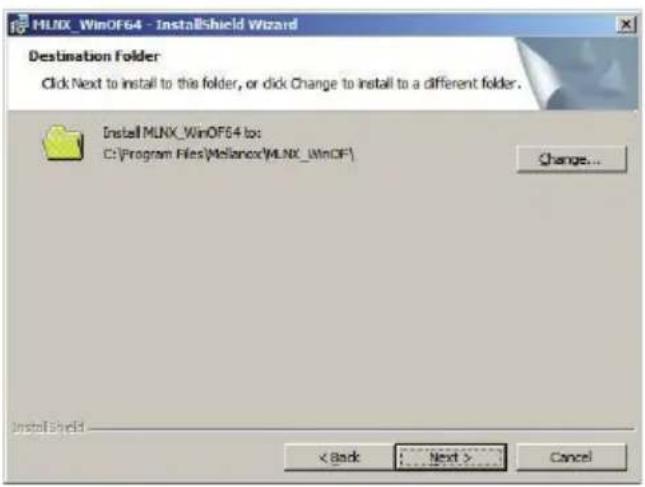
- Select a setup type and click Next to continue.
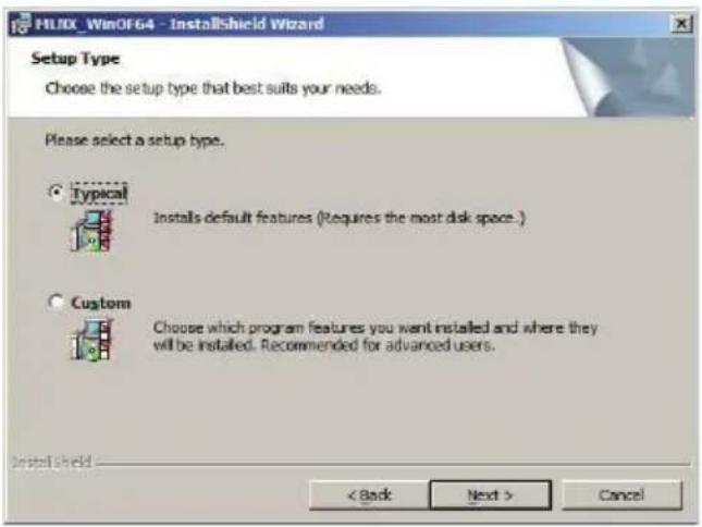
- The driver features you selected are being installed.
- Click your preferred options and click Finish to exit the wizard.
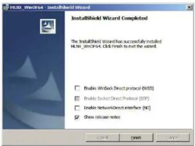
7.5.2 Red Hat® Enterprise Linux OS
You need to manually mount the Mellanox driver on a Red Hat® Enterprise Linux OS.

For users using SUSE Linux Enterprise Server OS, follow the general instructions in this section to mount the Mellanox driver on your system.
To mount the Mellanox driver
- Login to the system as root.
- Create a folder on the desktop and copy the latest Mellanox driver to the folder.

You can name the folder as you like.
![[root@localhost ~]# cd / [root@localhost /]# mkdir xxx [root@localhost /]# ■](/content/2026/06/1166783/images/48801a338cbd415ddc986ff9dada5f2fe18fccad69066dcc0433e1d78bd9aab6.jpg)
- Type the command line and mount the driver to the system.

The driver version and the OS label may vary. Ensure that the command line matches your driver version and operating system.
![[root@localhost -]# cd / [root@localhost /]# mkdir xxx [root@localhost /]# mount -o ro,loop /tmp/MLNX_OFED_LINUX-1.4-rhel5.3.iso /xxx]](/content/2026/06/1166783/images/ea2f7eefc0392829e9390cbd65cb0e156b6b411469827be02ede937f45813e19.jpg)
- Type the command line and install the driver.
![[root@localhost -]# cd / [root@localhost /]# mkdir xxx [root@localhost /]# mount -o ro,loop /tmp/MLNX_OFED_LINUX-1.4-rho15.3.iso /xxx [root@localhost /]# cd /xxx [root@localhost xxx]# ls Docs firmware 1686 1a64 minxofedinstall ppc64 src uninstall.sh x86_64 [root@localhost xxx]# ./minxofedinstall](/content/2026/06/1166783/images/667c07892aa0135b3db0d6d6cc495fa251577331129f14f20d225f991804cb22.jpg)
- All other Mellanox, OEM, OFED, or distribution IB packages will be removed. Press
to continue.
![[root@localhost ~]# cd / [root@localhost /]# mkdir xxx [root@localhost /]# mount -o ro,loop /tmp/MLNX_OFED_LINUX-1.4-rhel5.3.iso /xxx [root@localhost /]# cd /xxx [root@localhost xxx]# ls docs firmware i6B6 la64 minxofedinstall ppc64 src uninstall.sh x86_64 [root@localhost xxx]# ./mlnxofedinstall This program will install the MLNX_OFED_LINUX package on your machine. Note that all other Mellanox, OEM, OFED, or Distribution IB packages will be removed. Do you want to continue?[y/N]:](/content/2026/06/1166783/images/2f8aa00fe1d1afbef32cfb7722da1822b7e4954ec9a772dd0b01637dd692f527.jpg)
- The system starts uninstalling the previous version of OFED.
![[root@localhost -]# cd / [root@localhost /]# mkdir xxx [root@localhost /]# mount -o ro, loop /tmp/MLNX_OFED_LINUX-1.4-rho15.3.iso /xxx [root@localhost /]# cd /xxx [root@localhost xxx]# ls docs firmware i686 ia64 minxofedinstall ppc64 src uninstall.sh x86_64 [root@localhost xxx]# ./mlnxofedinstall This program will install the MLNX_OFED_LINUX package on your machine. Note that all other Mellamox, OEM, OFED, or Distribution IB packages will be removed. Do you want to continue?[y/N]:y Uninstalling the previous version of OFED](/content/2026/06/1166783/images/d1eb4f0233f311fb6c161eae7511415e729240d93ad1dca636a68e272618e54f.jpg)
- When the installation finishes, reboot your system to complete the installation.
![65:libibmad-static =********************************************************************************************** 66:libibmad-static =*********************************************** 67:libromacs-devel =********************************** 68:librdmack-devel =*************************¥ 69:libsdp-devel =**** {* *} * * * * * * * * * * * * * * * * * * * * * * * * * * * * * * * * * * * * * * * * * * * * * * * * * * * * * * * * * * * * * * * * * * * * * * 70:libsdp-devel =** =* =* =* =* =* =* =* =* =* =* =* =* =* =* =* =* =* =* =* =* =* =* =* =* =* + 71:opensn-devel =* =* =* =* =* =* =* =* =* =* =* =* =* =* =* =* =* =* =* =* =* =* + 72:opensn-devel =* =* =* =* =* =* =* =* =* =* =* =* =* =* + 73:opensn-static =* =* =* =* =* =* =* =* =* =* + 74:opensn-static =* =* =* =* =* =* =* + Device (15b3:6732): 0x:00.0 InfiniBand: Mellanox Technologies MT26418 [ConnectX IB DDR, PCIe 2.8 SGT/s] (rev a0) Link Width: 8x Link Speed: 5Gb/s Installation finished successfully. The firmware version 2.6.8 is up to date. Note: To force firmware update use '-force-fw-update' flag, warning: /etc/infiniband/openib.conf saved as /etc/infiniband/openib.conf.rpssave [root@localhost xxx]*](/content/2026/06/1166783/images/8d0812ec4b705480e088aa9dfa36494fe85140c1b929793221a3decf35d83aa7.jpg)

If your system has the latest firmware, no firmware update will occur. To force firmware update, type --force-fw-update.
7.6 Management applications and utilities installation
The support DVD that came with the motherboard package contains the drivers, management applications, and utilities that you can install to avail all motherboard features.
The contents of the support DVD are subject to change at any time without notice. Visit the ASUS website (www.asus.com) for updates.
7.6.1 Running the support DVD
Place the support DVD to the optical drive. The DVD automatically displays the Drivers menu if Autorun is enabled in your computer.

If Autorun is NOT enabled in your computer, browse the contents of the support DVD to locate the file ASSETUP.EXE from the BIN folder. Double-click the ASSETUP.EXE to run the DVD.
7.6.2 Drivers menu
The Drivers menu shows the available device drivers if the system detects installed devices. Install the necessary drivers to activate the devices.
The screen display and driver options vary under different operating system versions.
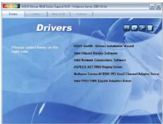
7.6.3 Utilities menu
The Utilities menu displays the software applications and utilities that the motherboard supports. Click an item to install.
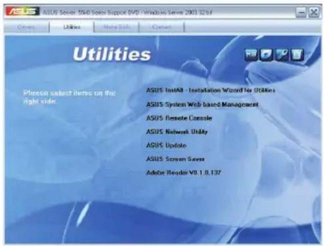
7.6.4 Make disk menu
The Make disk menu contains items to create the Intel ICH10R and LSI MegaRAID driver disks.
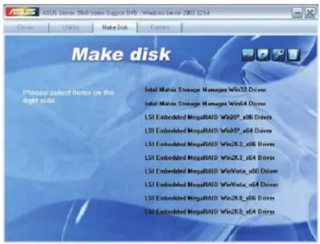
7.6.5 Contact information
Click the Contact tab to display the ASUS contact information. You can also find this information on the inside front cover of this user guide.
- Copyright © 2010 ASUSTeK COMPUTER INC. All Rights Reserved.
- Contents
- Chapter 1: Product introduction
- Chapter 2: Hardware setup
- Chapter 3: Installation options
- Chapter 4: Motherboard Info
- Chapter 5: BIOS setup
- Server menu 5-30
- Boot menu 5-32
- Exit menu 5-36
- Chapter 6: RAID configuration
- Setting up RAID 6-2
- LSI Software RAID Configuration Utility 6-4
- Intel ® Matrix Storage Manager Option ROM Utility 6-24
- Chapter 7: Driver installation
- RAID driver installation 7-2
- Management applications and utilities installation 7-29
- Notices
- Federal Communications Commission Statement
- Canadian Department of Communications Statement
- REACH
- Safety information
- Electrical Safety
- Operation Safety
- Lithium-Ion Battery Warning
- CD-ROM Drive Safety Warning
- CLASS 1 LASER PRODUCT
- Heavy System
- About this guide
- Audience
- Chapter 1: Product Introduction
- Chapter 2: Hardware setup
- Chapter 3: Installation options
- Chapter 4: Motherboard information
- Chapter 5: BIOS information
- Chapter 6: RAID configuration
- Chapter 7: Driver installation
- Conventions
- Typography
- References
- ASUS Server Web-based Management (ASWM) user guide
- ASUS websites
- Chapter 1
- System package contents
- Serial number label
- System specifications
- Front panel features
- Rear panel features
- Internal features
- RS704D-E6/PS4
- LED information
- Front panel LEDs
- LAN (RJ-45) LEDs
- ACT/LINK LED SPEED LED
- HDD status LED
- Chapter 2
- Hardware setup
- Chassis cover
- Removing the rear cover
- Central Processing Unit (CPU)
- Installing the CPU
- Installing the CPU heatsink and airduct
- System memory
- Overview
- Memory Configurations
- Memory population table
- Installing a DIMM
- Removing a DIMM
- Hard disk drives
- Expansion slot
- Installing an expansion card to the riser card bracket
- Configuring an expansion card
- Cable connections
- Pre-connected system cables
- Removable/optional components
- Replacing system fans
- Replacing power supply units
- Installing ASMB4 series management board (optional)
- Installing ASUS PIKE Riser Card (optional)
- Chapter 3
- installation options
- Rackmount rail kit items (optional)
- Attaching the rails to the server
- Attaching the rack rails
- Rackmounting the server
- Chapter 4
- Mothetherd Info
- Motherboard layout
- Layout contents
- Jumpers
- Clear RTC RAM (CLRTC1)
- To erase the RTC RAM:
- VGA controller setting (3-pin VGA\_SW1)
- DDR3 voltage control setting (4-pin LVDDR3\_SEL1; LVDDR3\_SEL2)
- LAN controller setting (3-pin LAN\_SW1, LAN\_SW2)
- Intel ^ ICH10R SATA port S/W RAID setting (3-pin RAID\_SEL1)
- Force BIOS recovery setting (3-pin RECOVERY1)
- Internal connectors
- Serial ATA connectors (7-pin SATA1, SATA2, SATA3, SATA4)
- USB connector (5-1 pin USB3; A-Type USB4)
- LPC debug card connector (14-1 pin LPC1)
- Serial General Purpose Input/Output connector (6-1 pin SGPIO1)
- BMC header (BMC\_FW1)
- Power Supply SMBus connectors (6-1 pin JP1, JP2)
- Proprietary power connectors
- (20-pin PWR1, 20-pin PWR2, 4-pin PWR3)
- System panel connector (20-pin PANEL1)
- System power LED (3-pin PLED)
- Message LED (2-pin MLED)
- System warning speaker (4-pin SPEAKER)
- Hard disk drive activity LED (2-pin HDDLED)
- Proprietary power button/soft-off button (2-pin PWRSW)
- Reset button (2-pin RESET)
- Auxiliary panel connector (20-pin AUX\_PANEL1)
- Internal LEDs
- Standby Power LED
- CPU warning LED (ERR\_CPU1, ERR\_CPU2)
- Chapter 5
- BIOS setup
- Managing and updating your BIOS
- AFUDOS utility
- Copying the current BIOS
- Updating the BIOS file
- ASUS CrashFree BIOS 3 utility
- Recovering the BIOS
- BIOS setup program
- BIOS menu screen
- Menu bar
- Navigation keys
- Menu items
- Sub-menu items
- Configuration fields
- Pop-up window
- Scroll bar
- General help
- Main menu
- System Time [xx:xx:xx]
- System Date [Day xx/xx/xxxx]
- SATA1-4
- Type [Auto]
- LBA/Large Mode [Auto]
- Block (Multi-Sector Transfer) M [Auto]
- PIO Mode [Auto]
- DMA Mode [Auto]
- SMART Monitoring [Auto]
- 32Bit Data Transfer [Enabled]
- IDE Configuration
- SATA Configuration [Enhanced]
- Hard Disk Write Protect [Disabled]
- IDE Detect Time Out (Sec) [35]
- AHCI Configuration
- AHCI CD/DVD Boot Time out [35]
- SATA Port1-4 [XXXX]
- System Information
- AMIBIOS
- Processor
- System Memory
- System Memory Information
- Advanced menu
- CPU Configuration
- C1E Support [Enabled]
- Hardware Prefetcher [Enabled]
- Adjacent Cache Line Prefetch [Enabled]
- MPS and ACPI MADT ordering [Modern ordering]
- Max CPUID Value Limit [Disabled]
- Intel(R) Virtualization Tech [Enabled]
- CPU TM Function [Enabled]
- Execute-Disable Bit Capability [Enabled]
- Intel(R) HT Technology [Enabled]
- Active Processor Cores [All]
- A20M [Disabled]
- Intel(R) SpeedStep (TM) Tech [Enabled]
- Intel(R) TurboMode tech [Enabled]
- Intel(R) C-STATE Tech [Enabled]
- C3 State [ACPI C3]
- C6 State [Enabled]
- C State package limit setting [Auto]
- C3 Auto Demotion [Enabled]
- ACPI T State [Disabled]
- Chipset Configuration
- CSI Links Speed [Full-Speed]
- CSI Frequency [Auto]
- CSI Isochronous [Disabled]
- CSI L1 [Disabled]
- CSI Power Optimization Policy [Static]
- Memory Frequency [Auto]
- Memory Mode [Independent]
- Memory ECC Function [Enabled]
- Double Rate Refresh [Auto]
- Demand Scrubbing [Enabled]
- Patrol Scrubbing [Disabled]
- NUMA Aware [Auto]
- Page Poilcy [Open]
- Adaptive Page [Disabled]
- Data Scramble [Enabled]
- Split Below 4 GB [Disabled]
- Channel Interleaving [6:1]
- Rank Interleaving [4:1]
- Memory Thermal Throttling [Disabled]
- Force VDD 1.5V [Disabled]
- North Bridge Configuration
- South Bridge Chipset Configuration
- USB Functions [Enabled]
- USB Port Configure [8+4 USB Ports]
- USB 2.0 Controller [Enabled]
- SLP\_S4# Min. Assertion Width [1 to 2 seconds]
- Serial Port1 Address [3F8/IRQ4]
- Serial Port2 Address [2F8/IRQ3]
- USB Configuration
- Legacy USB Support [Enabled]
- USB 2.0 Controller Mode [HiSpeed]
- BIOS EHCI Hand-Off [Enabled]
- PCIPnP Configuration
- Plug And Play O/S [No]
- PCI Option ROM Scan Order [Bus 0 First]
- Onboard Option ROM Priority [High]
- Onboard LAN1/2 Chip [Enabled]
- Onboard LAN1/2 Boot [PXE]
- Power On configuration
- Restore on AC Power Loss [Last State]
- Resume On Ring [Disabled]
- Resume On PME#(Wake On LAN) [Disabled]
- Resume On RTC Alarm [Disabled]
- Event Log Configuration
- View Event Log
- Clear Event Log
- Hardware Monitor
- CPU1/2 Temperature [xxx°C/xxx°F]
- Front Fan1-4 Speed [xxxxRPM] or [Ignored] / [N/A]
- Fan Speed Control [High Density Mode]
- I/O Virtualization
- SR-IOV Supported [Disabled]
- PCI Express Configuration
- Active State Power-Management [Disabled]
- ACPI Configuration
- Advanced ACPI Configuration
- ACPI 2.0 Support [Enabled]
- ACPI APIC Support [Enabled]
- BIOS-->AML ACPI table [Enabled]
- Headless mode [Disabled]
- Chipset ACPI Configuration
- APIC ACPI SCI IRQ [Disabled]
- High Performance Event Timer [Enabled]
- HPET Memory Address [FED00000h]
- General WHEA Configuration
- WHEA Support [Enabled]
- Server menu
- Remote Access Configuration
- Remote Access [Enabled]
- Serial port number [COM2]
- Serial Port Mode [57600 8,n,1]
- Flow Control [Hardware]
- Redirection After BIOS POST [Disabled]
- Terminal Type [VT-UTF8]
- Boot menu
- Boot Device Priority
- 1st \~ xxth Boot Device [XXXXXXX]
- Hard Disk Drives; CDROM Drives
- Boot Settings Configuration
- Quick Boot [Enabled]
- Full Screen Logo [Disabled]
- AddOn ROM Display Mode [Force BIOS]
- Bootup Num-Lock [On]
- Wait For 'F1' If Error [Enabled]
- Hit 'DEL' Message Display [Enabled]
- Interrupt 19 Capture [Enabled]
- Security
- Change Supervisor Password
- User Access Level [Full Access]
- Change User Password
- Password Check [Setup]
- Exit menu
- Exit & Save Changes
- Exit & Discard Changes
- Discard Changes
- Load Setup Defaults
- Chapter 6
- RAID confruration
- Setting up RAID
- RAID definitions
- Installing hard disk drives
- RAID controller selection
- Setting the RAID item in BIOS
- LSI Software RAID Configuration Utility
- Creating a RAID set
- Using Easy Configuration
- Using New Configuration
- Adding or viewing a RAID configuration
- Adding a new RAID configuration
- Initializing the virtual drives
- Using the Initialize command
- Using the Objects command
- Rebuilding failed drives
- Checking the drives for data consistency
- Using the Check Consistency Command
- Deleting a RAID configuration
- Selecting the boot drive from a RAID set
- Enabling WriteCache
- To enable WriteCache
- Intel ® Matrix Storage Manager Option ROM Utility
- Creating a RAID set
- Creating a Recovery set
- Deleting a RAID set
- Resetting disks to Non-RAID
- Recovery Volume Options
- To configure a recovery set
- Exiting the Intel ® Matrix Storage Manager
- To exit the utility
- Rebuilding the RAID
- Rebuilding the RAID with other non-RAID disk
- Rebuilding the RAID with a new hard disk
- Setting the Boot array in the BIOS Setup Utility
- Chapter 7
- RAID driver installation
- Creating a RAID driver disk
- ICH10R INTEL RAID Driver
- ICH10R LSI RAID Driver
- Installing the RAID controller driver
- Windows® Server OS
- To an existing Windows ® Server OS
- Red Hat® Enterprise Linux OS 4.7/4.8
- Red Hat® Enterprise Linux OS 5.0
- SUSE Linux OS
- Intel ® chipset device installation
- LAN driver installation
- VGA driver installation
- Mellanox ConnectX DDR PCI Gen2 Channel Adapter driver installation (For RS702D-E6/PS8; RS704D-E6/PS8)
- Windows operating system
- Red Hat® Enterprise Linux OS
- Management applications and utilities installation
- Running the support DVD
- Drivers menu
- Utilities menu
- Make disk menu
- Contact information
Brand : ASUS
Model : RS704D-E6/PS8
Category : Server