AV800-2T1 - Video recorder Arecont Vision - Free user manual and instructions
Find the device manual for free AV800-2T1 Arecont Vision in PDF.

| Product Type | Network Video Recorder (NVR) |
| Brand | Arecont Vision |
| Model | AV800-2T1 |
| Dimensions (W x D x H) | 430 x 300 x 44 mm (1U rackmount) |
| Weight | 2.5 kg |
| Power Supply | 12V DC, 3A |
| Power Consumption | 36 W max |
| Video Inputs | 8-channel IP camera support |
| Recording Resolution | Up to 8MP per channel |
| Storage Capacity | Supports 2 HDDs up to 4TB each |
| Network Interface | 2 x Gigabit Ethernet ports |
| Main Functions | Real-time recording, remote access, motion detection, playback |
| Operating Temperature | 0°C to 40°C |
| Mounting | Rackmount kit included |
| Safety | CE, FCC certified; overvoltage protection |
| Maintenance | Clean with dry cloth; avoid liquids |
| Spare Parts / Repairability | Replaceable HDD and fan; power supply available |
| Additional Information | Includes 2-year warranty |
Frequently Asked Questions - AV800-2T1 Arecont Vision
User questions about AV800-2T1 Arecont Vision
0 question about this device. Answer the ones you know or ask your own.
Ask a new question about this device
Download the instructions for your Video recorder in PDF format for free! Find your manual AV800-2T1 - Arecont Vision and take your electronic device back in hand. On this page are published all the documents necessary for the use of your device. AV800-2T1 by Arecont Vision.
USER MANUAL AV800-2T1 Arecont Vision
8 Channel with PoE Switch
AV800-0T2
AV800-2T1
AV800-4T0
16 Channel with PoE Switch
AV1600-0T2
AV1600-4T1
AV1600-8T0
natural_image
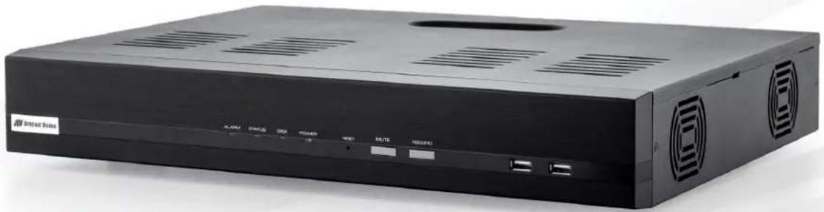
Exterior view of a black integrated device with ventilation slots and ports (no visible text or symbols on body)Contents
Package Contents....5
Camera Overview....7
Series Features .... 7
Preparation....10
HDD Installation....11
Power on the NVR 12
Connect to the NVR....13
Connect IP Cameras 15
Live View 16
Settings....21
Network Settings....22
Time and Date....26
Storage 28
Users & Privileges 30
Border Settings 31
Channel 32
Video Parameters....37
Recording 39
Scheduling 40
OSD 42
System Information 43
Log Viewer 44
System Event 44
Maintenance 48
- Do not attempt to service a damaged unit yourself. Refer all servicing to qualified service personnel.
- Wiring methods shall be in accordance with the National Electrical Code/NFPA 70/ANSI, and with all local codes and authorities having jurisdiction. Wiring should be UL Listed and/or Recognized wire suitable for the application.
- Always use hardware e.g. screws, anchors, bolts, locking nuts etc. which are compatible with mounting surface and of sufficient length and construction to insure a secure mount.
- Power cord shall be connected into a grounded outlet.
- This product is for indoor use only.
- This products is not meant for mobile surveillance applications.
- This product shall be installed in a well-ventilated and dust-free environment.
- Only use Arecont Vision recommended HDDs for this product
- This product shall be kept away from all liquids.
- This product shall be kept away from all liquids.
- Keep this product away from direct sunlight and heat resources
- Do not drop this product or subject it to physical shock.
- Power off this product and unplug the power cable if odor or smoke comes from it.
Package Contents
This equipment should be unpacked and handled with care. The original packaging is the safest container in which to transport the unit and can be used if returning the unit for service. The package contains:
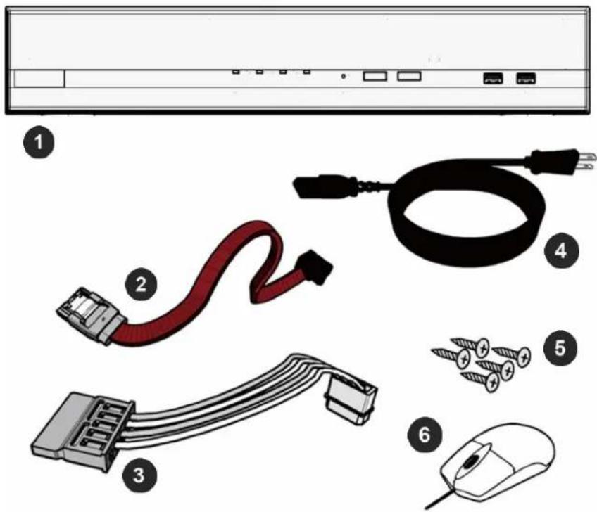
| Reference # | Description |
| 1 | 1x AV NVR PoE Network Video Recorder |
| 2 | SATA Data cable (2pcs for AVXXX-0T2 models/ 1pcs for AVXXX-XT1 models/ 0pcs for AVXXX-XT0 models) |
| 3 | SATA Power cable (1pcs for AVXXX-0T2 and models/ 0pcs for AVXXX-XT1 and AVXXX-XT2 models) |
| 4 | 1x Power cord cable |
| 5 | Screws for installed HDDs (8pcs for AVXXX-0T2 models/ 4pcs for AVXXX-XT1 models/ 0pcs for AVXXX-XT0 models) |
| 6 | 1x Mouse |
| 1x Quick installation guide | |
| 1x CD (User manual and Searching tool) |
Warranty Information
Global (3 Year) Limited Warranty
ARECONT VISION warrants to Purchaser (and only Purchaser) (the "Limited Warranty"), that: (a) each Product shall be free from material defects in material and workmanship for a period of thirty-six (36) months from the date of shipment (the "Warranty Period"); (b) during the Warranty Period, the Products will materially conform with the specification in the applicable documentation; (c) all licensed programs accompanying the Product (the "Licensed Programs") will materially conform with applicable specifications. Notwithstanding the preceding provisions, ARECONT VISION shall have no obligation or responsibility with respect to any Product that (i) has been modified or altered without ARECONT VISION's written authorization; (ii) has not been used in accordance with applicable documentation; (iii) has been subjected to unusual stress, neglect, misuse, abuse, improper storage, testing or connection; or unauthorized repair; or (iv) is no longer covered under the Warranty Period. ARECONT VISION MAKE NO WARRANTIES OR CONDITIONS, EXPRESS, IMPLIED, STATUTORY OR OTHERWISE, OTHER THAN THE EXPRESS LIMITED WARRANTIES MADE BY ARECONT VISION ABOVE, AND ARECONT VISION HEREBY SPECIFICALLY DISCLAIMS ALL OTHER EXPRESS, STATUTORY AND IMPLIED WARRANTIES AND CONDITIONS, INCLUDING THE IMPLIED WARRANTIES OF MERCHANTABILITY, FITNESS FOR A PARTICULAR PURPOSE, NON-INFRINGEMENT AND THE IMPLIED CONDITION OF SATISFACTORY QUALITY. ALL LICENSED PROGRAMS ARE LICENSED ON AN "AS IS" BASIS WITHOUT WARRANTY. ARECONT VISION DOES NOT WARRANT THAT (I) THE OPERATION OF THE PRODUCTS OR PARTS WILL BE UNINTERRUPTED OR ERROR FREE; (II) THE PRODUCTS OR PARTS AND DOCUMENTATION WILL MEET THE END USERS' REQUIREMENTS; (III) THE PRODUCTS OR PARTS WILL OPERATE IN COMBINATIONS AND CONFIGURATIONS SELECTED BY THE END USER; OTHER THAN COMBINATIONS AND CONFIGURATIONS WITH PARTS OR OTHER PRODUCTS AUTHORIZED BY ARECONT VISION OR (IV) THAT ALL LICENSED PROGRAM ERRORS WILL BE CORRECTED.
For RMA and Advance Replacement information visit http://www.arecontvision.com
Camera Overview
The Arecont Vision AV NVR ^™ is a stand-alone network video recorder with a built in 8- or 16- channel PoE switch. The AV NVR ^™ features a custom designed user interface with user-friendly features such as instant playback, power status monitoring, and plug-and-play support for all Arecont Vision cameras. When coupled with Arecont Vision's industry leading camera technology, the AV NVR ^™ provides a cost-effective and easy-to-use solution for small to medium sized installations.
Series Features
- Ideal for Small (AV800) or Small to Medium (AV1600) Size Installations
- Works with Arecont Vision Brand Single and Multi-Sensor Cameras
- Up to 8 or 16 Channels (The Number of Sensors in a Camera = The Number of Channels on the NVR)
- Example (AV800):
4x Arecont Vision 5MP MicroDome Single Sensor Cameras (4 Channels) + 1x Arecont Vision 12MP SurroundVideo Omni (4 Channels) = 8 Channels
6x Arecont Vision 3MP MegaDome 2 Cameras (6 Channels) + 2x Arecont Vision 5MP MegaView 2 (2 Channels) = 8 Channels
- Example (AV1600):
4x Arecont Vision 5MP MicroDome® Single Sensor Cameras (4 Channels) + 3x Arecont Vision 12MP SurroundVideo® Omni (12 Channels) = 16 Channels
8x Arecont Vision 3MP MegaDome® 2 Cameras (8 Channels) + 8x Arecont Vision 5MP MegaView® 2 (8 Channels) = 16 Channels
- Makes Camera Setup and Configuration Easy with Auto Discover and Auto Configuration
• 2 SATA Storage Bays (Up to 12TB)
- (AV800) Up to 10 Megapixels resolution recording, including 4K resolution and 40MP Panoramic cameras
- (AV1600) Up to 5 Megapixels resolution recording, NOT including 4K Resolution and 40MP Panoramic Cameras
• H.265, H.264, MPEG4, and MJPEG Compression
- SNAPstream™ Support
- Free Mobile App for Remote Viewing and Playback (Please refer to the quick instruction guide for more details)
• Power Status Utility
- Instant Playback
Hardware Overview
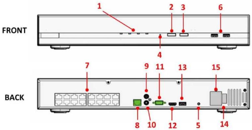
| Reference # | LEDs | Status | Definitions |
| 1 | Power | Solid Light | Power on |
| Disk | Solid Light | HDD functioning properly | |
| Blinking | Failed HDD | ||
| Off | No HDD/ HDD is offline | ||
| Status | Solid Light | Operating properly | |
| Blinking (100ms On/Off) | Restore factory default process/ Firmware update | ||
| Continuous Blinking (1000ms On/Off) | Failed firmware update | ||
| Alarm | Blinking | System/Camera event. Blinking lasts 10 seconds for each event | |
| Off | No event | ||
| Reference # | Buttons | Status | Procedure |
| 2 | Mute | Stop | Press to stop buzzer |
| Restore display defaults | Press and hold for 5 seconds | ||
| 3 | Record | On | Press and hold for 1 second to start manual recording (for all channels) |
| Off | Press and hold for 1 second to stop manual recording (for all channels) | ||
| 4 | Reset | Restore default | Press and hold for 10 seconds |
| Restart | Press and hold for 1 second | ||
| 5 | Power | On/ Off | Press and hold for 1 second |
| HW Force Off | Press and hold for 10 seconds | ||
| Buzzer Status | Status | Definitions | |
| Beep | Beep once | System is fully initiated/ Restart process has begun | |
| Long Beep | An event occurred | ||
| Reference # | Interfaces | Definitions | |
| 6 | USB | 2x USB 2.0 | |
| 7 | PoE | 8 independent 100 Mbps PoE network interfaces, Max 20W for single port, Max 200W in total, Up to IEEE 802.3at/20W per channel (AV800 Models) | |
| 16 independent 100 Mbps PoE network interfaces, Max 20W for single port, Max 200W in total, Up to IEEE 802.3at/20W per channel (AV1600 Models) | |||
| 8 | Ethernet | RJ-45 10M / 100M / 1000M | |
| 9 | Audio Input | 1-Ch, RCA | |
| 10 | Audio Output | RCA | |
| 11 | VGA | 1920x1080p / 60Hz, 1920x1080p / 50Hz, 1600x1200 / 60Hz, 1280x1024 / 60Hz, 1280x720 / 60Hz, 1024x768 / 60Hz | |
| 12 | HDMI | 4K (3840x2160) / 60Hz, 4K (3840x2160) / 30Hz, 1920x1080p / 60Hz, 1920x1080p / 50Hz, 1600x1200 / 60Hz, 1280x1024 / 60Hz, 1280x720 / 60Hz, 1024x768 / 60Hz | |
| 13 | USB | 1x USB 3.0 | |
| 14 | Power Switch | Power on /off | |
| 15 | Power In | 100~240V AC, 50/60Hz | |
Preparation
NOTE: This product is for indoor use only.
NOTE: This product shall be installed in a well-ventilated and dust-free environment.
NOTE: Keep this product away from direct sunlight and heat resources
- (Optional) If you would like to install HDDs or expand your HDD capacity, please refer to the "HDD installation" section of this manual.
NOTE: AV800-4T0 and AV1600-8T0 do not have a spare interface for additional HDDs.
-
Connect supplied AC power cord to the power input (#15) on the NVR
-
Connect a Cat 5e cable to the LAN 1 port (#8) on the NVR
-
(Optional) Connect a monitor to the HDMI (#12) or VGA (#11) interface on the NVR.
NOTE: You can refer to "Connect to the NVR" section for more details.
-
Connect supplied mouse to the USB port (#6 or #13) on the NVR
-
(Optional) Connect a keyboard to the USB port (#6 or #13) on the NVR
-
(Optional) Connect your Audio in/ out devise to the Audio In (#9) / Out (#10) interface on the NVR.
HDD Installation
NOTE: Only use Arecont Vision recommended HDDs for this product
- Unscrew the two screws from the NVR cover
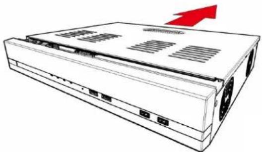
natural_image
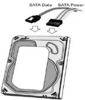
Line drawing of a server rack with ventilation slots and a red upward arrow indicating growth (no text or symbols)- Connect SATA Power cable and SATA Data cable on the NVR's main board, and install HDDs on the NVR by securely fastening the four screws on each HDD.
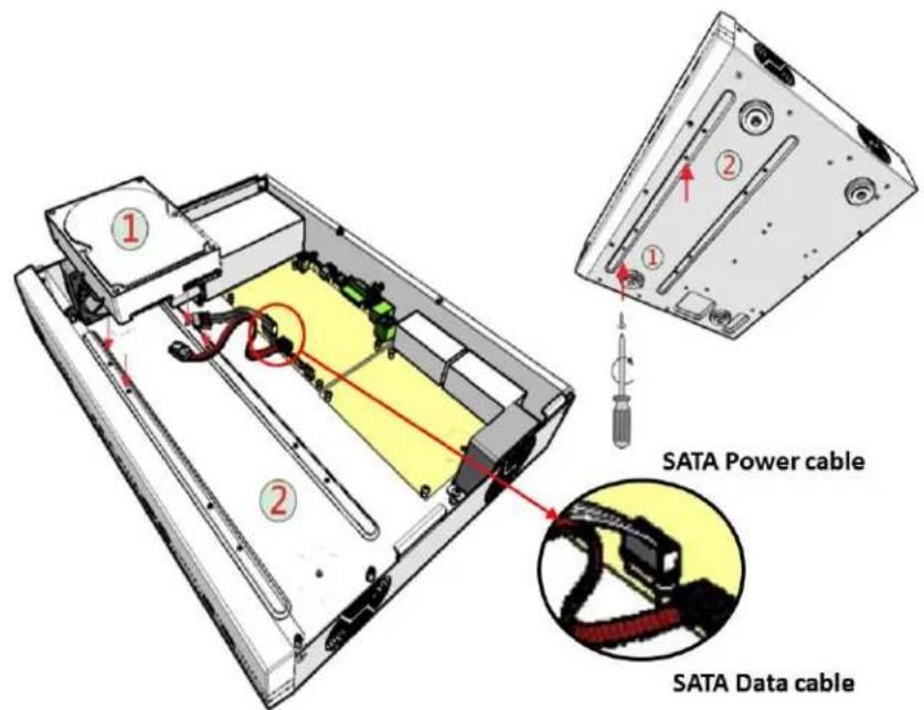
- Connect SATA Power cable and SATA Data cable to the HDD.
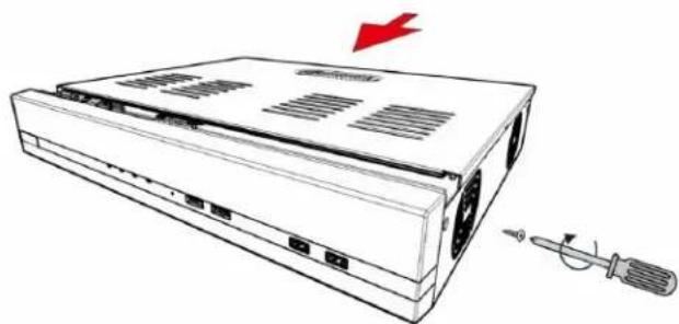
- Re-install the NVR cover and securely fasten the six screws
natural_image
Line drawing of a portable electronic device with ventilation slots and a screwdriver, no text or symbols presentNOTE: Before beginning to record, you must format the HDDs. Please refer to "Storage" section for instructions.
Power on the NVR
NOTE: The power cord shall be connected into a grounded outlet.
NOTE: Verify the power supply voltage before using this product.
- Plug AC power cord into 100 to 240V AC outlet.
- Turn power switch (#15) on.
- Click power button (#5)
- Power indicator (#1) will show a solid light.
Connect to the NVR
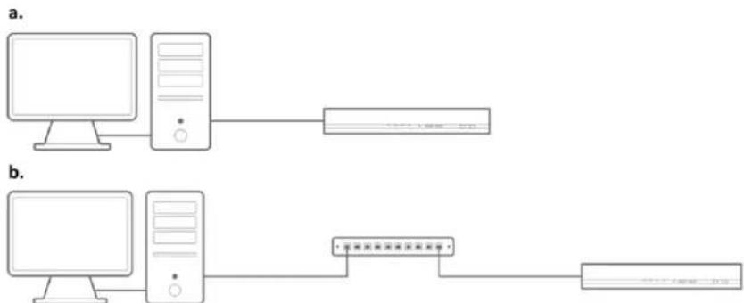
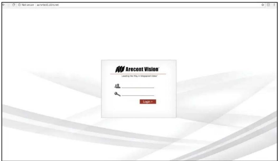
There are three different methods to connect to the AV NVR: 1. Connect to the AV NVR directly with no PC, 2. Connect to the AV NVR via a laptop/ computer without a DHCP server, or 3. Connect to the AV NVR via a laptop/ computer with a DHCP server. The following will explain how to connect to the AV NVR via different methods:
1. Monitor and AV NVR only (no PC).
i. You should see the local user interface with login screen:

ii. Use the keyboard or mouse with a virtual keyboard to enter the default username "admin" and password "admin" to login to the AV NVR.
NOTE: You can find the virtual keyboard by clicking the icon,
NOTE: It's highly recommended that you change the password during initial setup.
NOTE: You can have 4 to 31 characters including upper and lower case letters, digits for both User Name and Password, and only allow four symbols: “.”, “@”, “_”, “-”.
- PC connected to the AV NVR (a) directly or (b) over a switch or a hub on the same network (see images below), and there is no DHCP server on. The default static IP of the AV NVR is "192.168.101.50".
Page | 13 support@arecontvision.com
i. Type the default IP address "192.168.101.50" into the web browser.

ii. The login screen will appear. Enter the default username "admin" and password "admin" to login to the AV NVR.
NOTE: It's highly recommended that you change the password during initial setup.
NOTE: You can have 4 to 31 characters including upper and lower case letters, digits for both User Name and Password, and only allow four symbols: “.”, “@”, “_”, “-”.
- PC connected to the AV NVR with a DHCP. You must use the "AV NVR Utility" to discover the NVR.
i. Find the "AV NVR Utility" from the supplied CD or at: http://www.arecontvision.com/softwares.php
ii. Install the "AV NVR Utility" and launch the tool.
iii. You will see the IP address of the AV NVR appear in the utility.
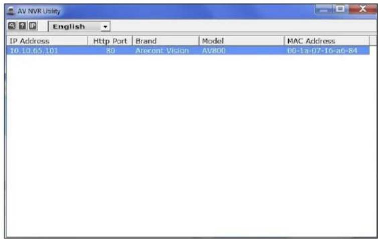
iv. Double-click the IP address or type the IP address to the web browser to access the web user interface, and enter default username "admin" and password "admin" to login to the AV NVR.
NOTE: It's highly recommended that you change the password during initial setup.
NOTE: You can have 4 to 31 characters including upper and lower case letters, digits for both User Name and Password, and only allow four symbols: “.”, “@”, “_”, “-”.
Connect IP Cameras
- Plug cameras into PoE ports (#7)
NOTE: This product supports Smart Plug-and-Play, so cameras will be set up and configured automatically in few minutes.
-
SurroundVideo and MicroDome Duo cameras will take four and two channels, so please make sure plug the next camera into the following PoE ports. For example, if one SurroundVideo camera plugs into Port#1, the next camera must plug into Port#5 since the SurroundVideo camera has taken Channel#1, #2, #3, and #4.
-
(If necessary) Visit Settings> Channel and add cameras by "Auto Search" or "Manually". For more details, please refer to "Channel" section for instructions.
Live View
There are six sections to the live view page: #1 Live View Main, #2 Camera Tree, #3 Saved Views, #4 Quick Status Box, #5 Instant Playback, and #6 Channel Setting.
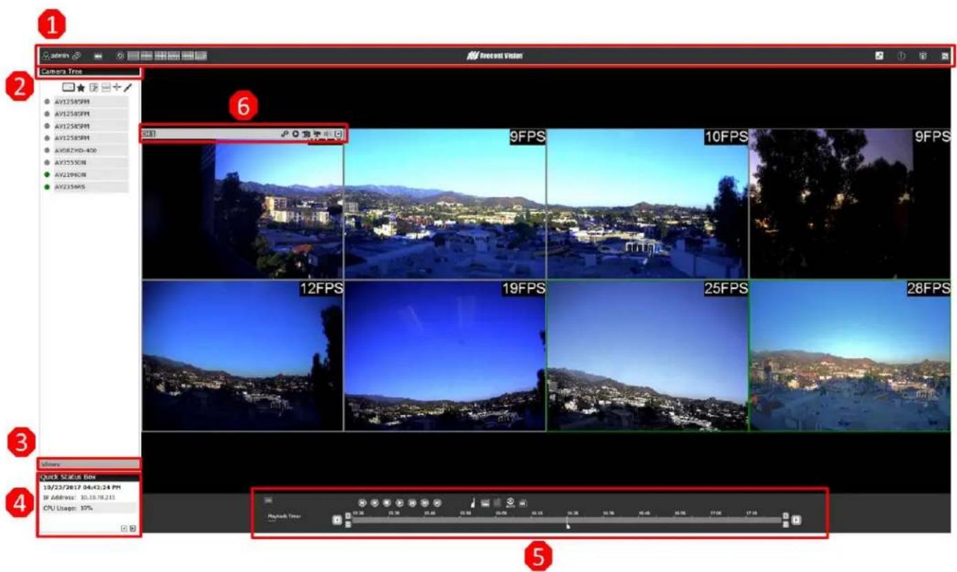
| Icon | Function | Description |
| #1 Live View Main | ||
 | User Configuration | Displays the name of the current user.Configure:Language Settings/ User Settings/ Locking the screen/Logout (Please refer to “Users & Privileges” section for more details) |
 | Settings | Visit “Settings” page(Please refer to “Setting” chapter for more details) |
 | Synchronized Playback | Visit “Synchronized Playback” page(Please refer to “Synchronized Playback” chapter for more details) |
 | View Sequence | Configure the cycle interval (10s/ 20s/ 30s/ 45s/ 60s).Click “Start/ Stop” to start/ stop switching views:1. On “Camera Tree” screen: switch between cameras based on current screen layout selected.2. On “Saved Views” screen: switch between Saved Views. |
Screen LayoutAV800-XXX AV1600-XXX AV1600-XXX | Select the icon for your screen layout.By clicking the same icon different times, you can switch to the next camera group. For example, click the “4 splits” icon once, the displayed channels are Ch1 to Ch4, then click the “4 splits” icon again, and the displayed channels are switched to Ch5 to Ch8. | |
 | Full Screen | Switch to full screen |
 | Camera Event Notification | The icon will flash when cameras receive Motion Detection\Digital Input\ Camera Disconnect notifications.The notification will have channel/ date/ time/ event type information.Click to play the Event Recorded videoClick to delete the event notification. |
 | NVR Event Notification | Receive notifications if a warning sound is triggered or the HDD of the NVR failed to record data. |
 | Channel Status | Check the channel status:Camera Name/ IP Address/ HTTP Port/ Recoding Types/ Stream Status (Codec/ Resolution/ Frame rate/ Bit rate) |
| #2 Camera Tree | ||
 | Channel Number | Display the Channel Number and select the camera order by Number or Name |
 | Save View | Name the current view and save it.This function will help to quickly display your desired views when needed. |
 | Drag and Drop | Enable the drag and drop function. It allows user to drag a channel from the camera tree and drop to the desired view location. |
| [TT80] | OSD | View OSD (on screen display).(Please refer to “OSD” section for more details) |
| [HSOZ] | Aspect Ratio | Expand the width and height of the image to fit the video layout or keep the original aspect ratio for all channels. |
| [45WS] | Edit Channel Name | Edit the channel name.Click to save Channel nameClick to cancel |
| #3 Saved Views | ||
| (TWCS) | Edit the name of Saved Views | Edit the name of Saved Views |
| (ness) | Select Saved Views | Select the Saved Views for View Sequence or for deleting |
| (TAZW) | Delete Saved Views | Delete the Saved Views you have select |
| #4 Quick Status Box | ||
| 10/24/2017 01:35:42 PM | Date/ Time of the NVR(Please refer to “Time and Date” section for more details) | |
| IP Address: 10.10.70.213 | IP address of the NVR(Please refer to “Network Settings” section for more details) | |
| CPU Usage: 27% | Current CPU usage of the NVR | |
| Move to Next or Previous Page | ||
| Disk Status: Normal | The Disk Status comes from Disk SMART utility (Self-Monitoring, Analysis and Reporting Technology). It will show “Warning” if the HDD status is unhealthy.(Please refer to “Storage” section for more details) | |
| Day of Retention: 10 Day(s) | Days of recording available. | |
| Disk Temp.: 117°C | Current temperature of the HDD | |
| #5 Instant Playback | ||
| Instant Playback time bar | Different colors on the time bar reflect different recorded data types.(Please refer to “Border Settings” section for more details) | |
| Click to move to “Previous” time period.Click to move to “Next” time period.Click to “Zoom In” and change the time scale.Click to “Zoom Out” and change time scale. | ||
| Marker for the current playback time | Click the desired time point on the time bar or drag the marker to the desired time point, the channel will start to playback from the marked time point. | |
| Click to mark the start time for the exported video or the bookmark.Click to mark the end time for the exported video or the bookmark.Click to delete the marks.Click to export the marked video.Click to save as a bookmark.Click to enable/ disable auto playback. Auto playback allows user to click the time point on the time bar and automatically start playback.Click to return to live view. | ||
 | Click to play previous frameClick to play next frameClick to Fast Rewind: 2x, 4x, 8x, 16x, 32xClick to Fast Forward: 2x, 4x, 8x, 16x, 32xClick to start playbackClick to stop playbackClick to pause playback | |
| #6 Channel Setting | ||
| Channel Settings | Visit the “Channel Settings” page.(Please refer to “Channel” section for more details) | |
| Instant Playback | Start instant playback. | |
| Snapshot | Take a snapshot. | |
| Manual Record | Start manual recording.NOTE: all manual recording will be stopped once you leave or close the live view page. | |
| Audio | Enable audio functionality.NOTE: This function needs the camera support this function. | |
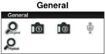
| More Options | General | Enable digital zoom functionality.Take a snapshot.Take three consecutive snapshots.Enable microphone functionality.NOTE: Disabled by default if the camera doesn’t support this function. |
| #6 Channel Setting | ||
 | Channel SettingsVisit the “Channel Settings” page.(Please refer to “Channel” section for more details) | |
 | Instant PlaybackStart instant playback. | |
 | SnapshotTake a snapshot. | |
 | Manual RecordStart manual recording.NOTE: all manual recording will be stopped once you leave or close the live view page. | |
 | AudioEnable audio functionality.NOTE: This function needs the camera support this function. | |
  |   Enable digital zoom functionality. Enable digital zoom functionality. Take a snapshot. Take a snapshot. e three consecutive snapshots. e three consecutive snapshots. Enable microphone functionality.NOTE: Disabled by default if the camera doesn’t support this function. Enable microphone functionality.NOTE: Disabled by default if the camera doesn’t support this function. | |

Arecont Vision ^TM
| Enable zoom functionality of a PTZ camera. | ||
Network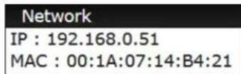 | IP address and MAC address of the camera | |
Lens Control | Zoom/ Focus/ Iris functionsNOTE: Disabled by default if the camera doesn't support these functions. | |
Preset Point Control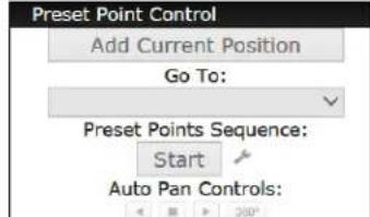 | Preset point control function can be activated if the camera supports this function. | |
  | Web User Interface:Users can select the video stream they would like to show on this channel grid, or can duplicate the channels.Local User Interface:Users can select the non-displayed video stream to show on this channel grid.NOTE: Local display does not support channel duplication. | |
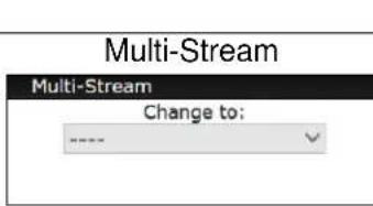
| User can select the suitable video stream to be displayed if the multi-stream function has been set.(Please refer to “Channel” section for more details) |
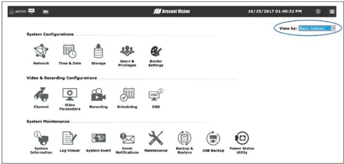
Settings
There are two modes, "Basic Options" and "Advance Options".
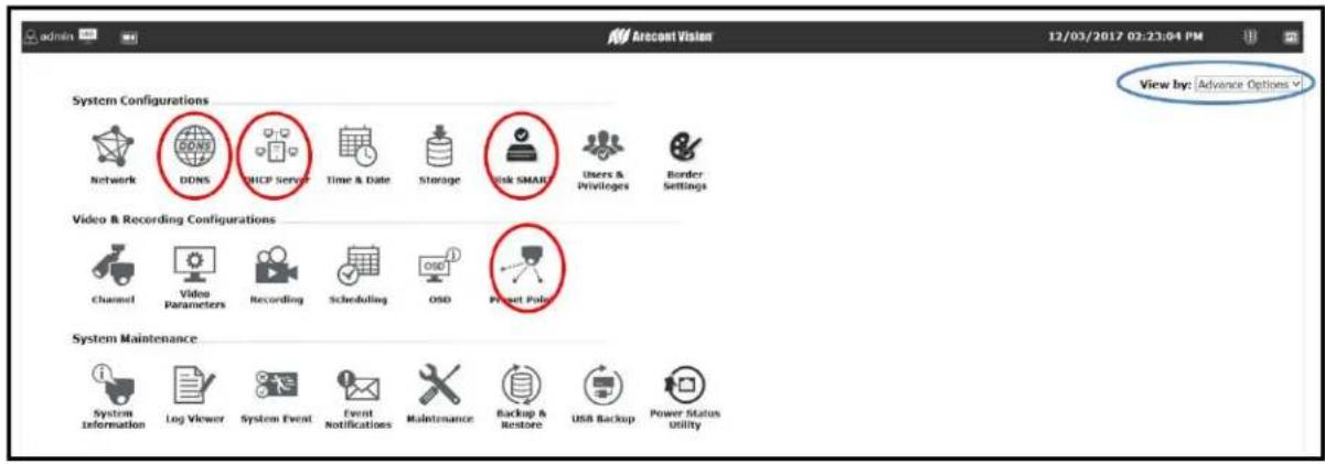
Network Settings

Configuration
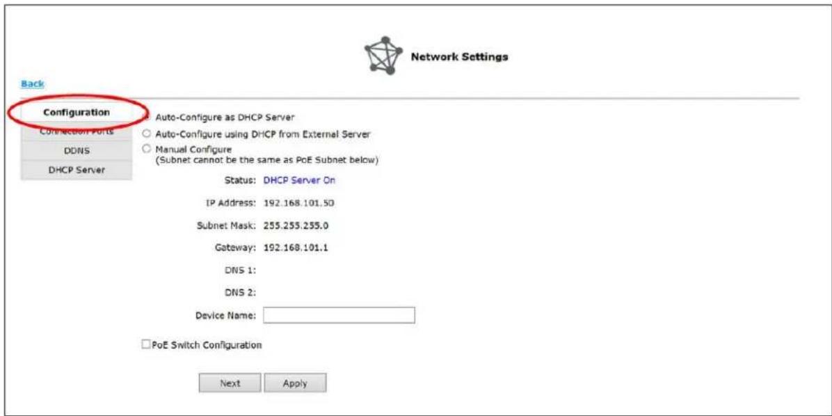
The AV NVR supports three connection types that can be configured depending on how the network is setup:
1. Auto-Configure as DHCP Server
This option sets the AV NVR to configure network settings automatically.
a. When no other DHCP server is in the network, the AV NVR will use the default IP address, 192.168.101.50, and turn on the built-in DHCP servers. The AV NVR will become a DHCP server.
b. When a DHCP server is on the network, the AV NVR will get the IP address from the external DHCP server, and turn off the built-in DHCP server.
c. Users will not be able to change IP settings when this mode is selected.
d. Users cannot turn on/off built-in DHCP server.
2. Auto-Configure using DHCP from External Server
support@arecontvision.com

Arecont Vision ^TM
User Manual
This option sets the AV NVR as a DHCP client.
a. The AV NVR will get the IP address from the external DHCP server. If no DHCP server is on the network, the AV NVR will default to the default IP address, 192.168.101.50, and the built-in DHCP server will remain off.
b. Users will not be able to change IP settings when this mode is selected.
c. Users cannot turn on/off built-in DHCP server.
3. Manual Configure
This option sets the AV NVR to use a static IP address.
a. Users can edit the IP settings, subnet mask, default gateway address and DNS server address for the AV NVR.
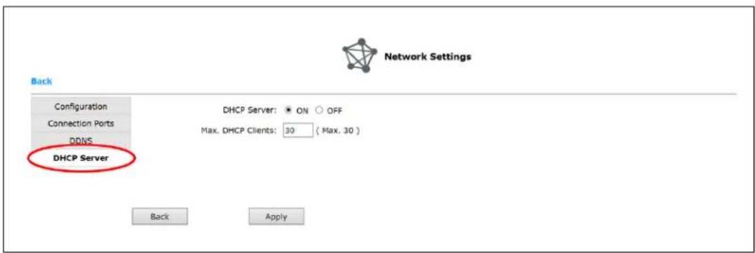
b. Users can turn on or off the built-in DHCP server via the "DHCP Sever" section:
- User can also configure the network settings of the PoE switch by checking PoE Switch Configuration:
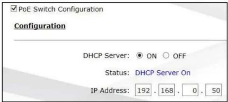
NOTE: The network of PoE switch is isolated from the outside network, so if you would like to access camera web interface, you need to connect your laptop/PC directly to the PoE ports.
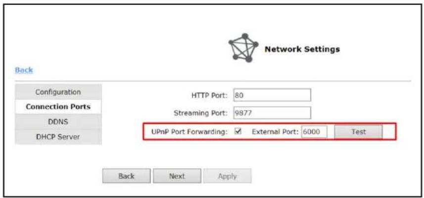
Connection Ports
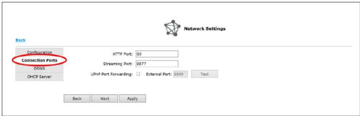
You can edit your port information in this section. Default HTTP port is 80 and Streaming port is 9877.
NOTE: Event trigger may not work for cameras that are placed outside of your local network or on the Internet until the UPnP Port Forwarding is enabled in both the AV NVR and the router.
DDNS
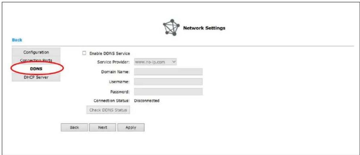
Remote users must use a DDNS service to access the AV NVR. This is useful if the AV NVR is placed on the Internet with a dynamic public IP address. Once the DDNS service is properly setup, users can access the AV NVR remotely with the DDNS domain name.
- Service Provider: The AV NVR supports "DynDNS" or "No-IP" DDNS services. For more information, please visit www.dyndns.com & http://www.noip.com/
- Domain Name: enter the domain name you registered with the DDNS service
-
Username: enter the username you registered with the DDNS service
-
Password: enter the password you registered with the DDNS service
NOTE: Once you have the DDNS function successfully up and running, please configure port forwarding for the AV NVR HTTP port (default 80) and the streaming port (default 9877) on your router/gateway for remote viewing. You can then type in http://yourddnsdomain in the browser to access the AV NVR remotely for live view.
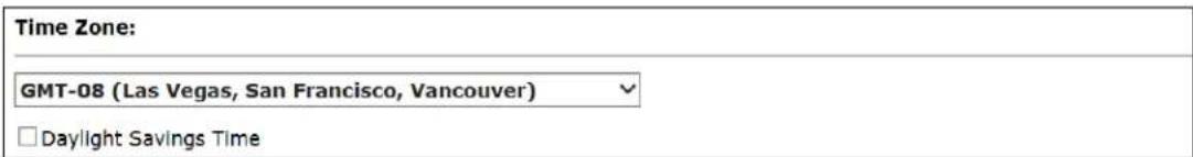
Time and Date

Time & Date
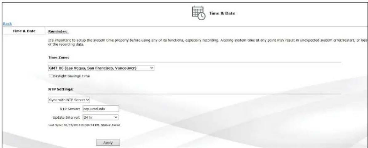
NOTE: To avoid incorrect display times for recorded video and/or inconsistent display time of the event logs please ensure you have set the time and date correctly per your local time zone.
- Time Zone: select the correct time zone for your location, and check "Daylight Saving Time" if necessary.
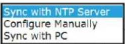
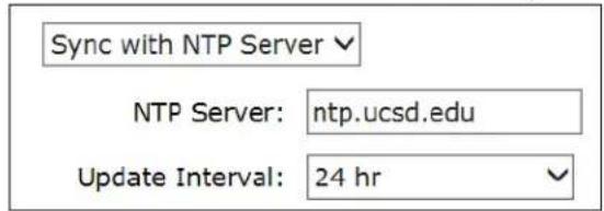
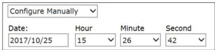
- NTP Settings: select one of the following options for synchronize time and date: "Sync with NTP Server", "Configure Manually", or "Sync with PC":
User Manual
a. Sync with NTP Server: enter the hostname or the IP address of a valid NTP server and select how often the AV NVR should synchronize the time with this NTP server.
b. Configure Manually: use the drop-down list and configure the time manually.
c. Sync with PC: synchronize the time with the computer that you are currently using to access the AV NVR.
Storage
Storage Status
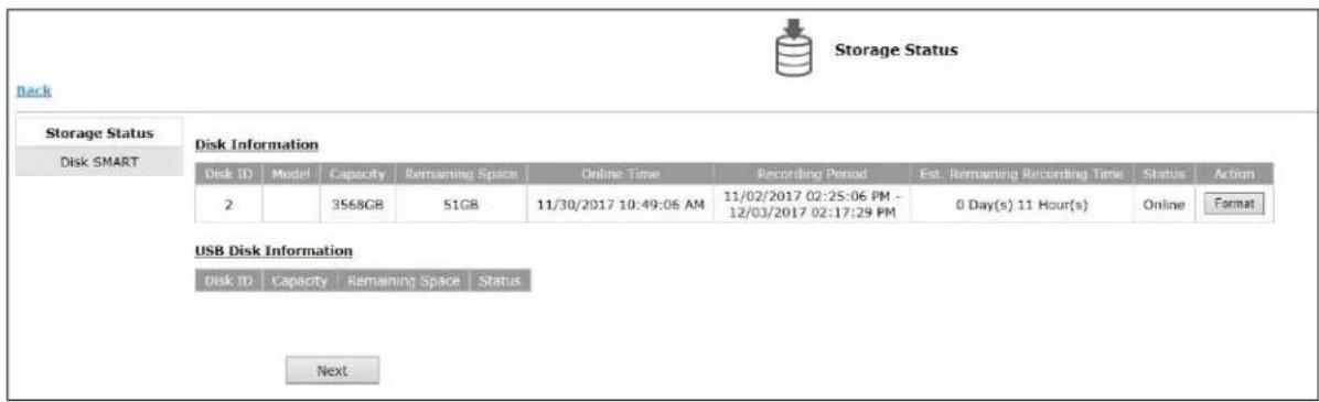
This section displays the HDD general information.
NOTE: If you have installed your own hard disk you must format prior to use..
NOTE: The HDD will be formatted in EXT4 file system.
NOTE: USB HDDs must be formatted in advance in a FAT32 file system.
NOTE: Please plug in the USB HDD only after the AV NVR is fully started. The internal HDDs will NOT be properly detected if the AV NVR is powered on with USB HDD plugged in during start up.
Disk SMART
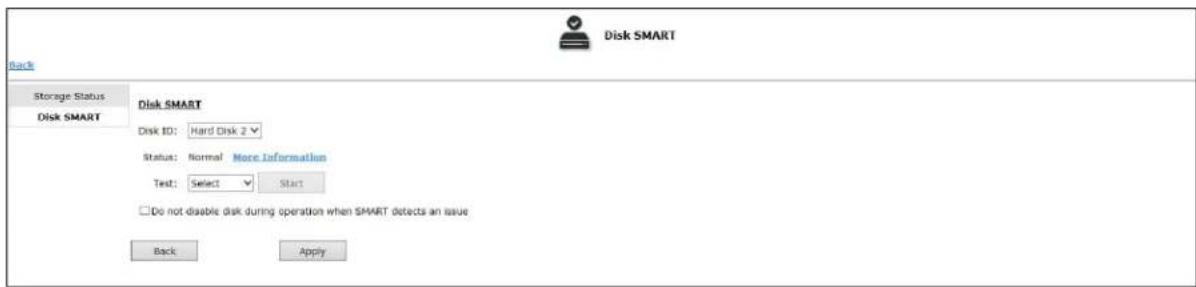
Using Disk SMART (Self-Monitoring, Analysis and Reporting Technology) tool, user can check the HDDs health.
User Manual
- Select the HDD to launch SMART test
- Select "Short Test" or "Long Test". With "Short Test", the tool will check key attributes such as how long the drive has run and how many times the drive has moved data out of damaged areas. With "Long Test", the tool will run full S.M.A.R.T test with each attribute.
NOTE: Click More Information for more detailed statistics on the SMART test. - Click "Start" to begin the process.
Users & Privileges

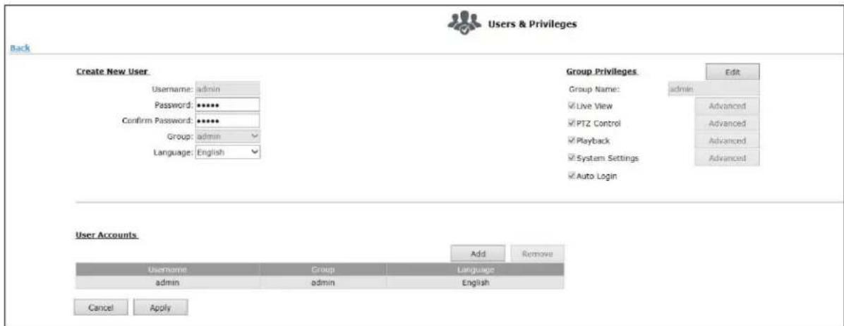
NOTE: Each AV NVR comes with a built-in "admin" account with password "admin". It's highly recommended that you change the password during initial setup.
Create a new user
- Click "Add" to add new user
- Enter a username and password
- Select a group from the "Group" drop-down menu to assign the new user to a group
- Click "Apply" to finish
Group Privilege
Group Privilege is where you can create multiple customized access policies for situations if you need the AV NVR to be accessed by users other than the administrator. The AV NVR comes with seven built-in groups and five built-in privilege profiles, except for the “admin” and the “guest” accounts; the other five groups are fully customizable or you can simply assign a group with one of the default privilege profiles. You can, however, assign more than one user to the “admin” account if you wish to do so. The guest account comes with a “view-only” privilege in the “Live View” page, and users in this group do not have the right to make any changes in the “Live View” page or have access to pages other than the “Live View” page.
To change a group configuration, after clicking "Add" to add new user account, click "Edit" to change Group privileges. You can also change the group name.
Border Settings

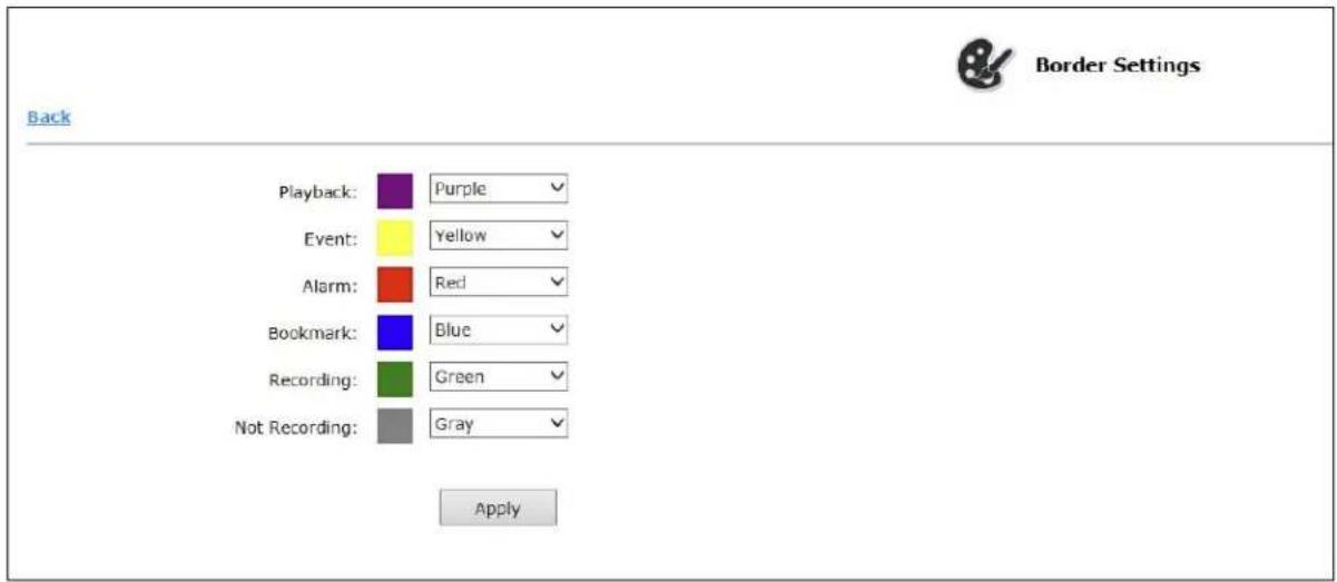
In the section, you can assign different colors to the various functions if you are not satisfied with the default color choices.
Channel

Channel List
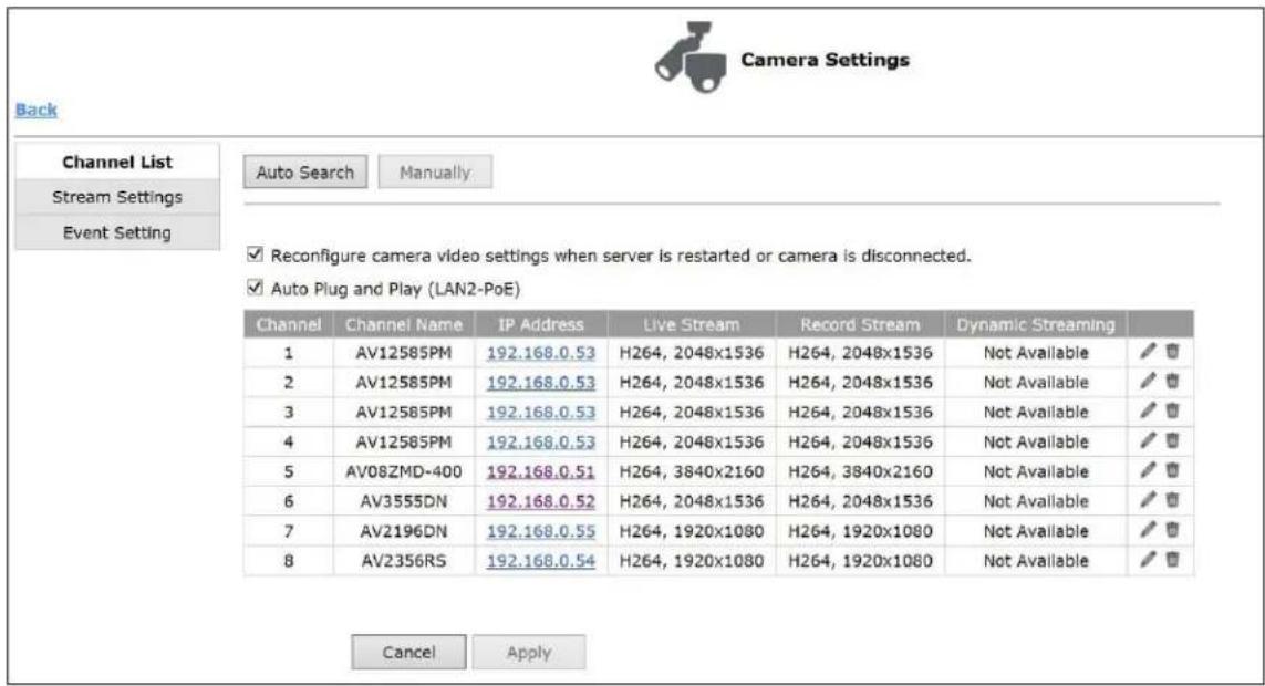
In the section, you can add cameras by "Auto Search" or "Manually".
Auto Search
After clicking "Auto Search", you will see the results displayed. Double clicking the camera in the list will redirect you to the "Stream Settings" page.
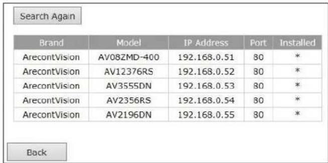
NOTE: If cameras are marked with " * " in the search result, it means those cameras are already configured and connected to the AV NVR.
Adding Cameras Manually
After clicking "Manually", enter the camera's IP address and credentials.
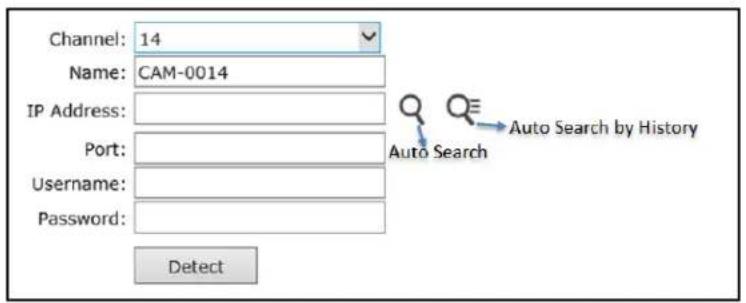
NOTE: "Auto Search" is to execute a new camera search, and you can add camera from the list.
NOTE: "Auto Search by History" is to show the search history from the database, saving time for user.
Stream Settings
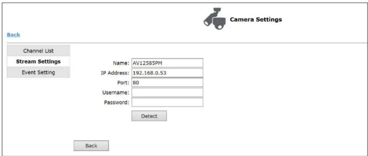
After entering the username and password of the camera, click "Detect", and you can start to configure the stream settings and see the camera preview (Live view):
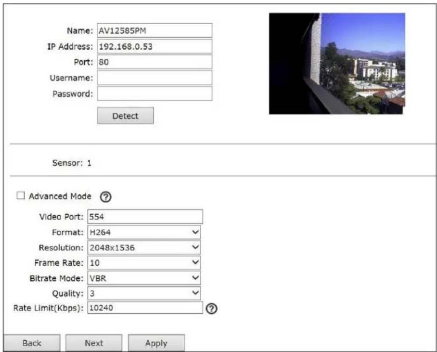
In this section, users can change the video streaming settings:
| Function | Description |
| Video Port | RTSP streaming port, default value is 554 |
| Format | Select video type: H.264, MJPEG |
| Resolution | Select the streaming resolution from the dropdown list |
| Frame Rate | Select the streaming frame rate from the dropdown list |
| Bitrate Mode | Select the bitrate control mode: VBR (Variable Bitrate Control), CBR (Constant Bitrate Control)NOTE: Only available when selecting H.264 video format |
| Quality | Select video quality from the dropdown list: “1” is the lowest quality and “5” is the highest qualityNOTE: Only available when selecting VBR mode |
| Rate Limit(kbps) | Specify the bitrate limit: 0~65535kbpsNOTE: Only available when selecting VBR mode |
| Bitrate | Select the bitrate for the CBR from the dropdown listNOTE: Only available when selecting CBR mode |
Enable "Advanced Mode" to set up multiple streams (only if cameras supports multi-streaming).
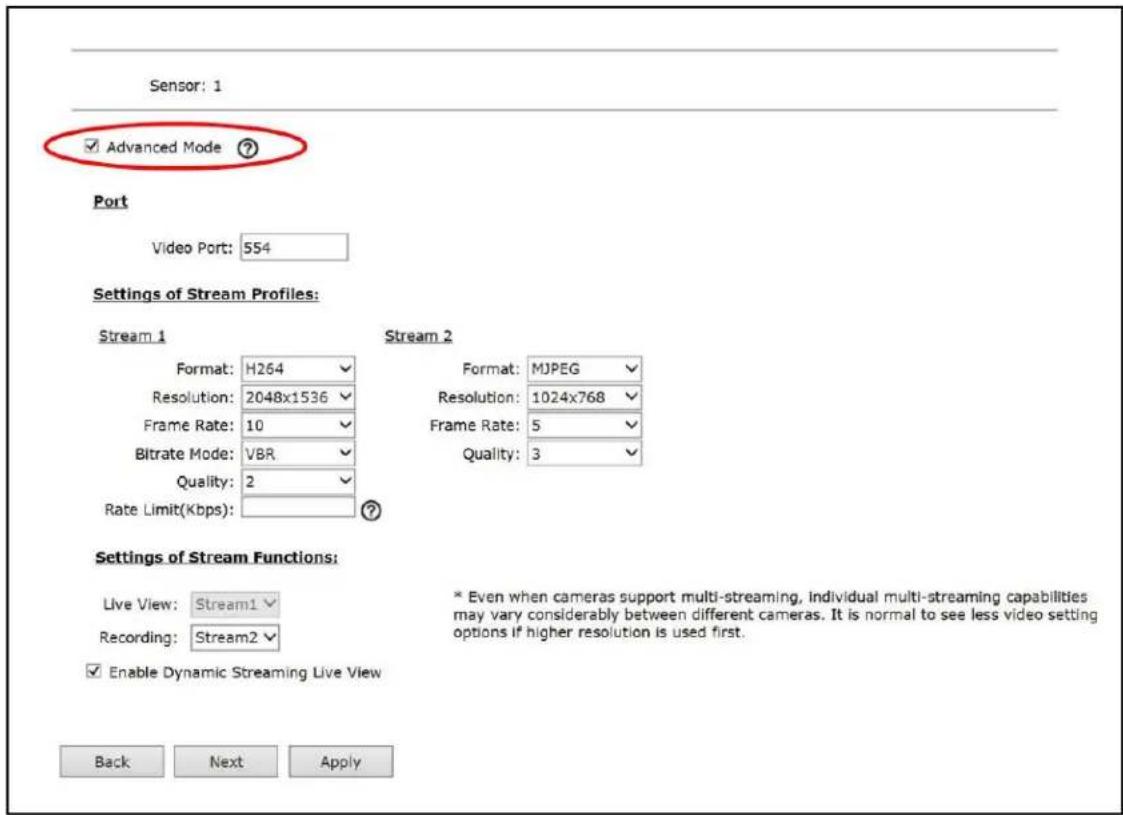
If you enable this function, you must setup at least two streams for the camera. Some cameras are capable of four streaming profiles. After finishing all stream settings, click "Apply" to finish adding the camera.
Enable Dynamic Streaming Live View, to automatically display the best stream during live viewing.
NOTE: The higher value of the "Quality" the higher image quality you will get.
Event Setting
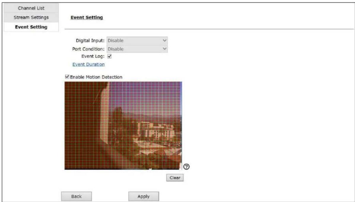
In this section, you can setup the Motion Detection Zone on the AV NVR side (default is full motion). If the camera supports Digital Input, you can also setup the input event here.
NOTE: "Event Duration" will take you to the "Scheduling" settings page for pre-alarm/ post-alarm configuration.
Video Parameters

NOTE: For more advanced parameter settings, you will need to visit the camera's web interface. To do so you need to connect your laptop/PC directly to the PoE ports.
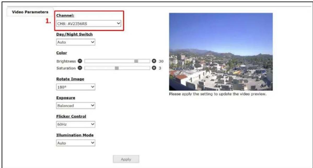
In this section, users can change basic camera parameters. Before changing the settings, users need to select a channel.
| Function | Description |
| Day/Night Switch | Force to Day mode will manually place the camera in color mode. Force to Night mode will manually place the camera in black and white mode. Auto mode is the default setting enabling the camera to automatically change from color (Day) mode to black and white (Night) mode as illumination levels drop off. |
| Color | Brightness adjusts image brightness. Saturation adjusts image color saturation or the amount of color in an image. Lower saturation gives a duller, faded image. |
User Manual
| Rotate Image | Rotate image 0, 90, 180, or 270 degrees. |
| Exposure | Adjust exposure time settings. Short exposures result in less light, giving darker images whereas longer exposures can flood an image with light, giving washed out images in the presence of a lot of light. Additionally, motion blur is reduced under short exposures and increased under long exposures.High speed mode has shortest exposure time, and Moonlight mode has longest exposure time. |
| Flicker Control | Prevent flicker caused by the power line frequency of lighting. This parameter would have no effect when the dominate light is sunlight. |
| Illumination Mode | Adjusts the camera's white balance computation based on the scene's illumination.Auto mode enables the camera to adjust for illumination automatically whileIndoor/Outdoor mode use presets assuming the camera is indoors or outdoors. |
Recording

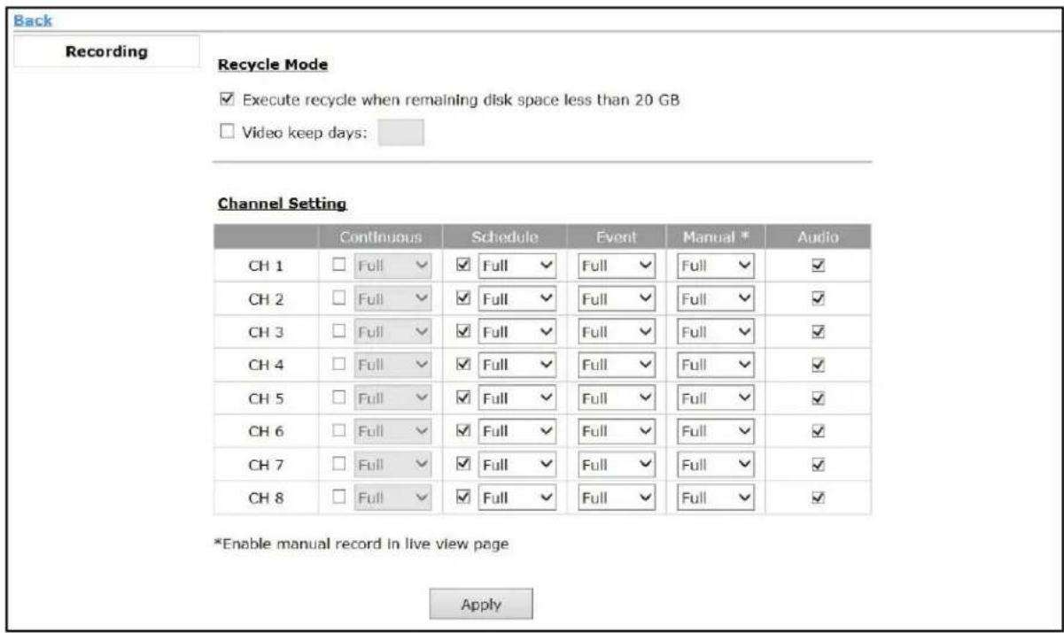
Recycle Mode
Default setting is to enable cycle recording when remaining disk space less than 20GB. Video keep days allows users to set a specified number of days to retain recorded video.
Channel Setting
This section allows users to set I-frame only or Full frames (I+P frames) recording. Recording only I-frames will require less storage as it is more lossy. Users also can disable audio recording (record video only) for particular channels.
Scheduling

Scheduling
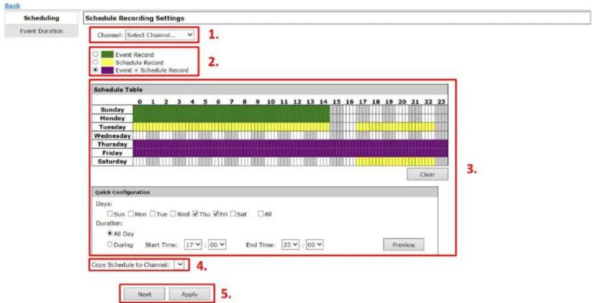
- The channel drop-down menu allows you to select which camera's recording schedule you would like to update.
NOTE: The default setting for all channels is Event Record at all times, and you can click the "Clear" button to start over.
-
Select which type of recording you would like to update. There are three types: Event Record, Schedule Record, and Event + Schedule Record.
-
You can use the schedule table to set the time range by clicking the cell, or you can also use the "Quick Configuration" to define recording time ranges one by one on the timetable by simply checking what days you would like to perform recording and specifying the recording duration by either choosing "All Day" or enter a start and end time for specific recording duration. "Preview" button allows you to visualize the schedule you set.
NOTE: You can repeat Step 2 and Step 3 for different kind of recording types.
- Select Copy Schedule to Channel if you would like to set the same recording schedule to other cameras.
- Once you are done creating the schedule(s), click the "Apply" button.
support@arecontvision.com

Arecont Vision™
Event Duration
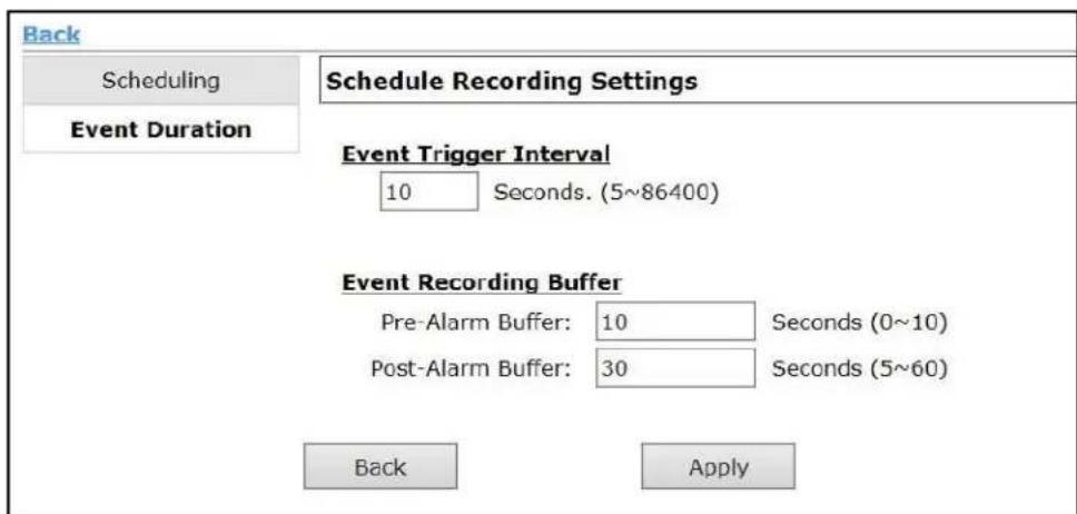
Event Trigger Interval allows you to set a time interval to create logs. For example, if the event trigger interval is set at 10 seconds and you have a 1 minute event, the result will be 6 logs.
Event Recording Buffer allows you to set the recoding interval before the event trigger (Pre-Alarm Buffer) or after the event trigger (Post-Alarm Buffer).
OSD

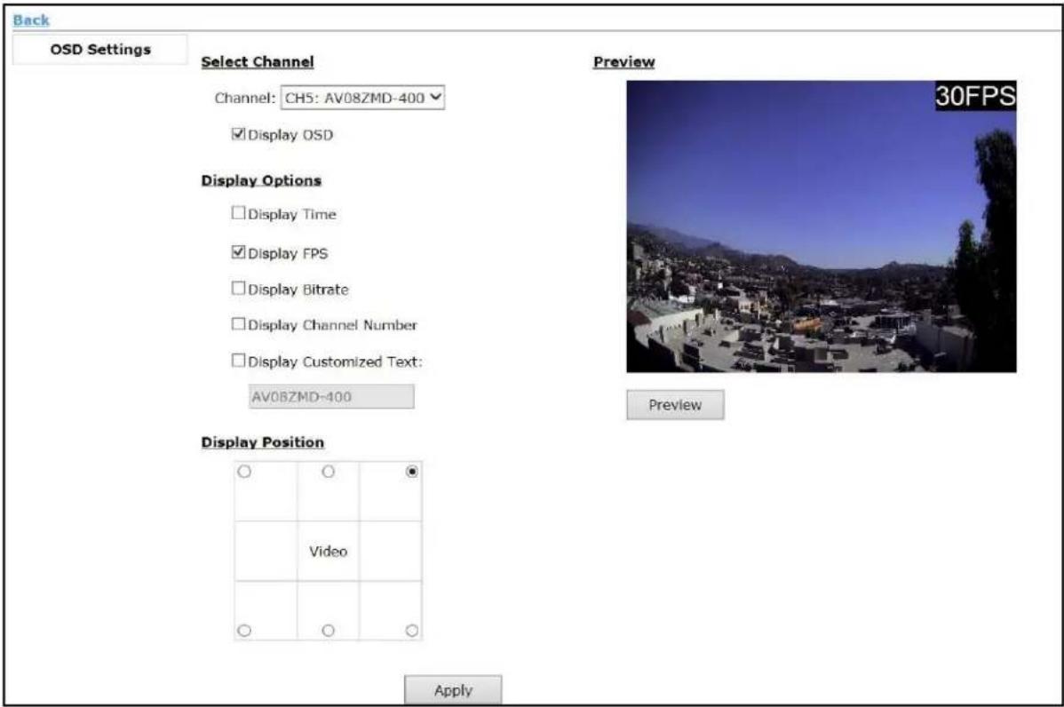
NOTE: Customized Text is only available on Web UI.
System Information

General Information
Device Name:
Model Name: AV-800
Firmware Version: v1.0.1.479
Device Up Since: 12/15/2017 11:49:26 AM
Network Information
Configuration: Auto Mode: ON Static IP
Device IP: 192.168.101.50
HTTP Port: 80
Streaming Port: 9877
MAC Address: 00:1A:07:16:A6:84
PoE MAC Address: 00:1A:07:16:A6:77
DHCP Server: ON
UPnP Port Forwarding: OFF
NOTE: Device IP, MAC address, DHCP Sever mentioned here are for this AV NVR device.
Log Viewer

Log Viewer
| ID | Time | Type | Sub-Type | CH | AP | IP | User | ||
| 511 | 12/11/2017 11:47:31 AM | Service | Reload Configuration | ||||||
| 512 | 12/11/2017 11:47:24 AM | Configuration | Channel added, or edited | 5 | AUTO | ||||
| 513 | 12/11/2017 11:47:07 AM | Service | Event log space shortage | ||||||
| 514 | 12/11/2017 11:46:56 AM | System | Formatted Internal Disk 2 inserted | ||||||
| 515 | 12/11/2017 11:46:03 AM | Service | Device starts OK, running 1.0.1.479 | ||||||
| 516 | 12/11/2017 11:45:09 AM | Configuration | Reset to factory default | 192.168.101.51 | admin | ||||
| |< | Prev | Next | >| | 511~516/516 | |||||
| Clear Log | Export Log | ||||||||
In this section, you will find all of the log information for the cameras and AV NVR device such as camera connected/disconnected, User login/logout, Device restarted, Start recycling disk, Event log recycle, and so on. Also, you can click "Export Log" button to export all logs or logs from a specific time range.
System Event

System Event
System Event
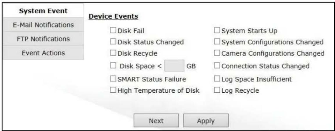
In this section, users can define which conditions will trigger an event.
E-Mail Notifications
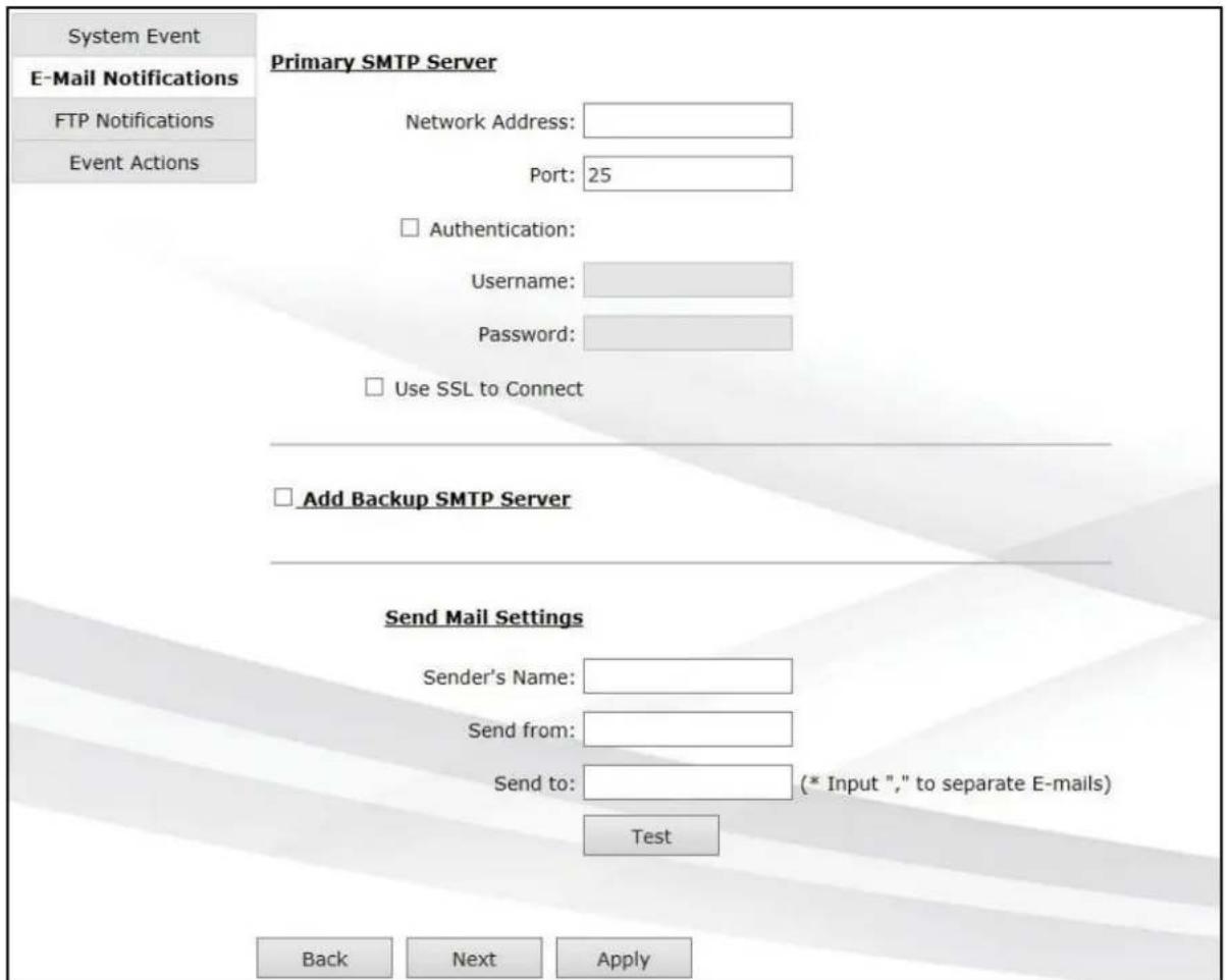
In this section, users can set up e-mail notifications for triggered events:
- Enter Network Address (hostname or the IP address) of the SMTP server
- Enter Port of the SMTP server
- Specify Sender's name in the "Sender's name" field
- Enter the sender's email address in Send from field
- Enter the receiver's email address in Send to field
- Check Authentication and enter Username and Password of the SMTP server if it requires authentication
- Click Test to verify all information is correct and the connection to the SMTP server can be established successfully
- Click Apply to save the configuration
NOTE: The AV NVR supports SMTP servers that use base64 or MD5 authentication methods, and 3rd party free E-mail services such as Gmail are supported.
NOTE: You must enable the notifications in the "Event Actions" section.
FTP Notifications
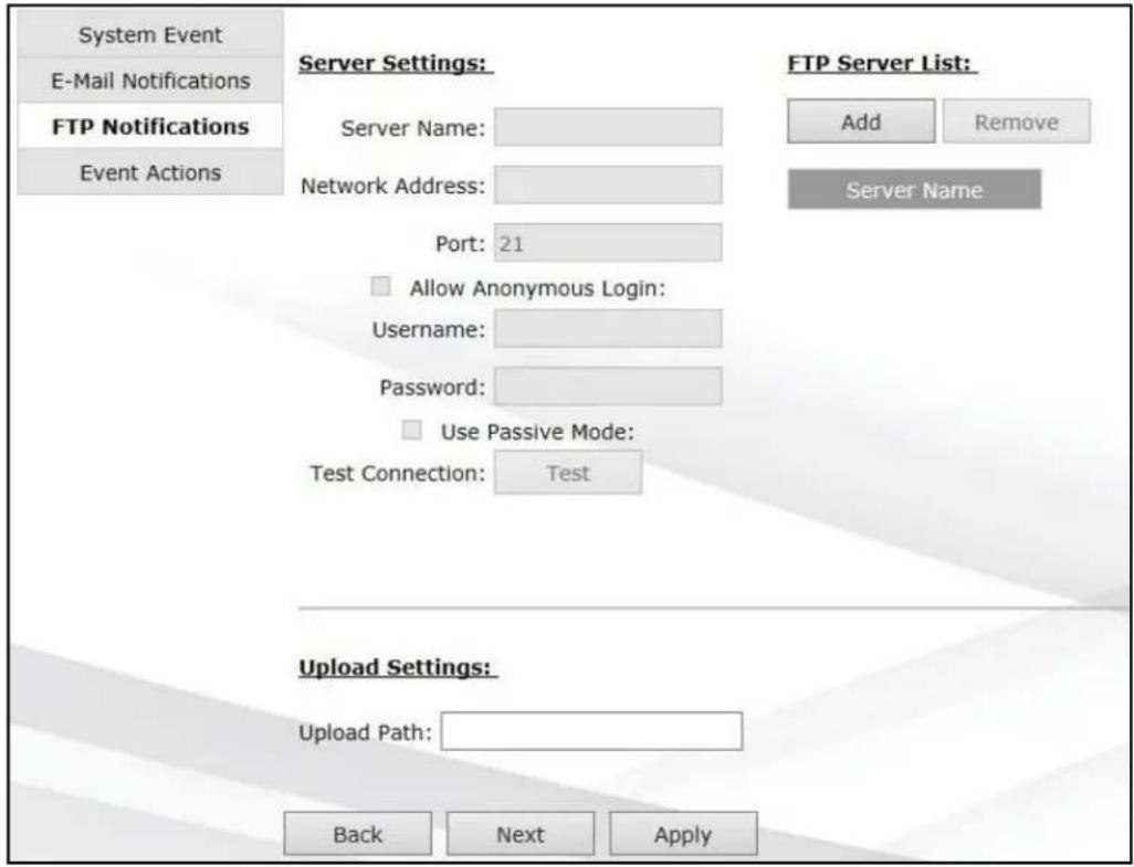
In this section, users can set up FTP notifications for triggered events:
- Specify Sever name in the "Sever name" field
- Enter Nextwork Address (hostname or the IP address) of the FTP server
- Enter the communication Port of the FTP server (Default port is 21.)
- Enter Username and Password of the FTP server if it's required
- Check Use Passive Mode if it's required or leaves it unchecked to use active mode
- Click Test to verify all information is correct and the connection to the FTP server can be established successfully
- Click Add for this FTP server
- Specify the upload folder path in Upload settings.
Below image is the example of the upload path of "Event" folder:

NOTE: You must enable the notifications in the "Event Actions" section.
Event Actions
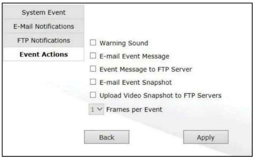
In this section, users can define how the notifications will be sent.
NOTE: Event trigger may not work for cameras that are placed outside of your local network or on the Internet until the "UPnP Port Forwarding" is enabled in both the AV NVR and the router. To enable "UPnP Port Forwarding" in the AV NVR, please visit Connection Ports section and enable "UPnP Port Forwarding" as shown in the image below.
Maintenance

In this section, users can configure functions to maintain the AV NVR or cameras:
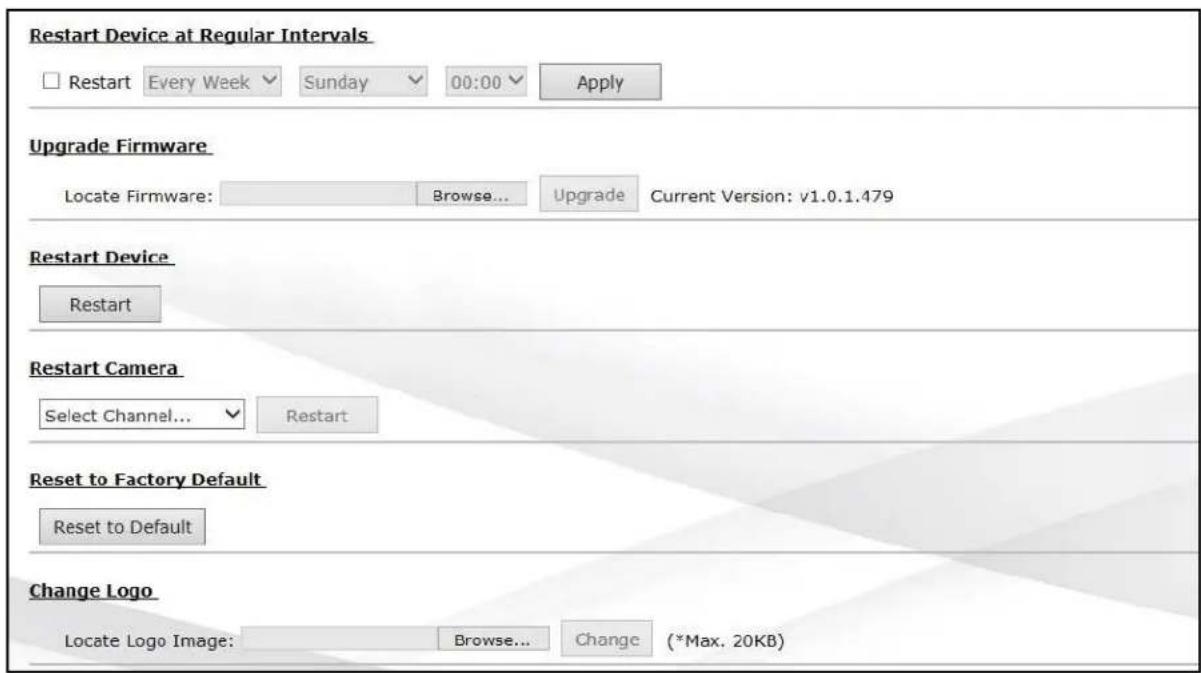
Restart Device at Regular Intervals: specify "Every Week" or "Every Month" to restart the AV NVR.
Upgrade Firmware:
- Before upgrading firmware, please backup configuration.
- Click "Browse" to locate the firmware file
- After selecting the firmware file, click "Upgrade"
NOTE: Upgrade Firmware UI is only available through Web Interface.
NOTE: The firmware file comes with a “.bin” file extension.
NOTE: If you would like to upgrade firmware on the local AV NVR directly instead of Web UI, here's the procedure:
- Rename the firmware file as "firmware.bin" (all lower case)
- Save the file from Step 1 to a USB flash drive (FAT32 format), and make sure the firmware is not in any folder
- Plug the USB flash drive to the USB port of the AV NVR
User Manual
- The AV NVR automatically closes the service and starts to upgrade the F/W.
- After the firmware updates completely, you will hear a beep.
- Ensure the status LED stops flashing then unplug the USB, and reboot the AV NVR.
- Check System Information and confirm the firmware upgrade was successful.
Restart Device: click "restart" to restart the AV NVR.
Restart Camera: select the camera you would like to reboot directly from the AV NVR.
Reset to Factory Default: click "Reset to Default" to reset the AV NVR's settings to the factory default values.
Change Logo: select the logo you would like to display on the AV NVR.
Backup & Restore
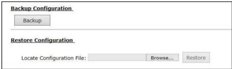
In this section, user can use Backup Configuration to save the AV NVR's settings to a local hard drive, and also can use Restore Configuration to restore the AV NVR's settings from a previously saved configuration file.
NOTE: On Web UI, the configuration can be backed up to or restore from a local computer. On local UI, the configuration can be backed up to or restore from a USB disk. It is required to plug in a USB disk formatted in FAT32 prior to using the backup and restore functions.
USB Backup

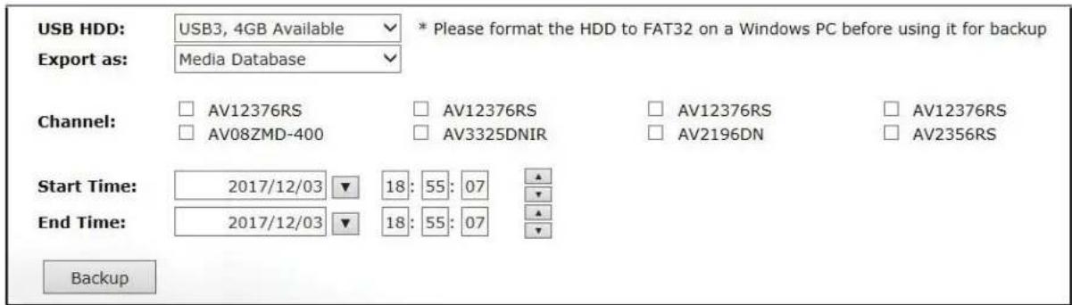
In this section, the user can create a backup file of the recorded data either as a database file (Media database) or as an AVI file to the connected USB disk. Here's the procedure:
- Select the USB disk from the drop-down menu USB HDD
- select the Channel you would like to backup the recording data from.
- Configure Start Time and End Time of the recording data and click the "Backup" button to begin.
NOTE: USB Hubs to extend the number of HDD connected to the AV NVR are not supported.
NOTE: Only one backup process can be performed at a time.
NOTE: Maximum 4 channels can be selected for backup.
NOTE: Only FAT32 USB disk is supported for backup.
NOTE: The USB disk needs to have more than 100MB remaining space.
NOTE: If multiple partitions are present on the disk, only the first partition will be detected and used for backup.
NOTE: A folder will be automatically created in the USB disk with a name format as "001A0716A684_20171218160245_20171218145507_20171218154619" (MAC_backupbuttonclicktime_starttime_endtime).
NOTE: Plug in the USB disk only after the AV NVR has completed startup and initialization, otherwise the HDDs will be incorrectly mounted.
NOTE: Use the AV NVR Media Player for playback (see the enclosed CD or download it from the link below: https://www.arecontvision.com/downloads.php).
Power Status Utility
other
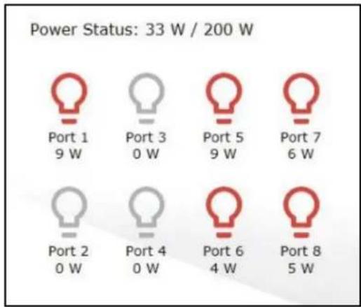
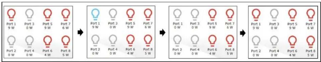
Power Status: 33 W / 200 W | Port | Power (W) | |---|---| | Port 1 | 9 | | Port 3 | 0 | | Port 5 | 9 | | Port 7 | 6 | | Port 2 | 0 | | Port 4 | 0 | | Port 6 | 4 | | Port 8 | 5 |In this section, user can monitor the power usage of each camera and which PoE ports have been connected. For example, in the image above, Port 1/5/6/7/8 have been connected, and their power usage are 9W, 9W, 4W, 6W, and 5W. Also, user can remotely cycle each PoE port by simply clicking the bulb icons. Below is an example of a power cycle on Port 1:
flowchart
graph LR
    A["Port 1<br>9 W"] --> B["Port 3<br>0 W"]
    B --> C["Port 5<br>9 W"]
    C --> D["Port 7<br>6 W"]
    E["Port 2<br>0 W"] --> F["Port 4<br>0 W"]
    F --> G["Port 6<br>4 W"]
    G --> H["Port 8<br>5 W"]

    I["Port 1<br>9 W"] --> J["Port 3<br>0 W"]
    J --> K["Port 5<br>9 W"]
    K --> L["Port 7<br>6 W"]
    M["Port 2<br>0 W"] --> N["Port 4<br>0 W"]
    N --> O["Port 6<br>4 W"]
    O --> P["Port 8<br>5 W"]

    Q["Port 1<br>0 W"] --> R["Port 3<br>0 W"]
    R --> S["Port 5<br>9 W"]
    S --> T["Port 7<br>6 W"]
    U["Port 2<br>0 W"] --> V["Port 4<br>0 W"]
    V --> W["Port 6<br>4 W"]
    W --> X["Port 8<br>5 W"]

    Y["Port 1<br>9 W"] --> Z["Port 3<br>0 W"]
    Z --> AA["Port 5<br>9 W"]
    AA --> AB["Port 7<br>6 W"]
    AC["Port 2<br>0 W"] --> AD["Port 4<br>0 W"]
    AD --> AE["Port 6<br>4 W"]
    AE --> AF["Port 8<br>5 W"]
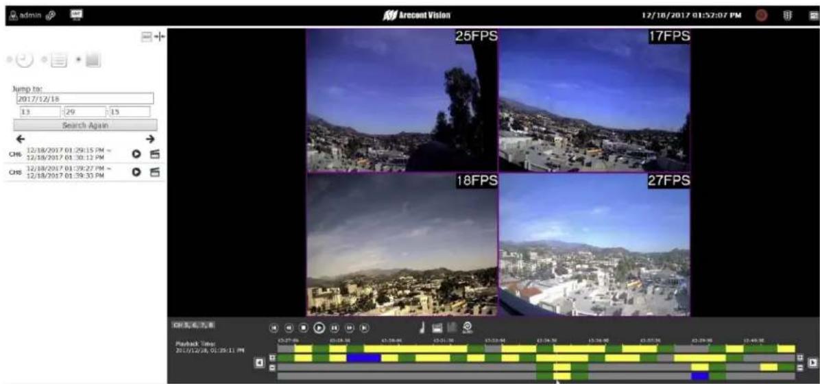
Synchronized Playback View
The AV NVR offers up to 4 channels of synchronized playback. There are three different search methods; 1. Search by Time, 2. Events, or 3. Bookmarks.
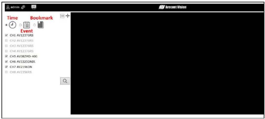
Search by Time

With Search by Time, users can search videos by specific time and date. Here are the steps:
User Manual
-
Select channels you would like to search (up to 4 channels)
-
Click the date on the calendar
NOTE: Different colors on the calendar represent different types of recorded video.
Defaults are: Green= Video record exists/ Yellow= Event trigger/ Red= Camera connection lost
- After specifying the time and date, you will see the record video on the playback time bar.
NOTE: Refer to Instant Playback in Live View Section for the further instructions on playback features.
Search by Event
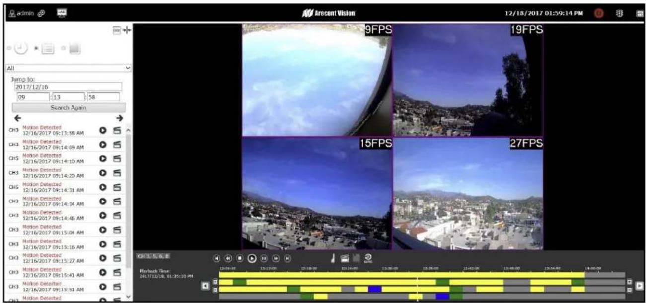
With Search by Time, users can search videos by specific date. Here are the steps:
- Select channels you would like to search (up to 4 channels)
-
Select which types of event trigger you would like to search on: "All", "Motion Detected", "DI event", and/or "Camera Disconnected".
-
Specify the time period
-
Click "Search Again"
-
You can view or export videos from the video list directly or you can use the playback time bar to perform playback.
NOTE: Refer to Instant Playback in Live View Section for the further instructions on playback features.
Search by Bookmark

With Search by Time, users can search videos by specific time and date. Here are the steps:
- Select channels you would like to search (up to 4 channels)
- Specify the time period
- Click "Search Again"
- You can view or export videos from the video list directly or you can use the playback time bar to perform playback.
NOTE: Refer to Instant Playback in Live View Section for the further instructions on playback features.
NOTE: You must bookmark recorded videos before using the "Search by Bookmark" method.
Support
- Arecont Vision FAQ Page Located at ArecontVision.com
-
Check the following before you call:
-
Restore AV NVR to factory default.
- Upgrade to the latest firmware by visiting ArecontVision.com.
- Restore camera to factory default with AV200 or the camera webpage.
- Upgrade to the latest firmware by visiting ArecontVision.com.
- Isolate the camera on a dedicated network and test with AV200.
-
Swap the "troubled" camera with a known good camera to see if the problem follows the camera or stays at the location.
-
Contact Arecont Vision Technical Support one of three ways:
-
Online Portal: Support.ArecontVision.com
- Phone: 1.818.937.0700 (option #1)
-
Email: support@arecontvision.com
-
Use the Arecont Vision software and AV NVR Utility located on the CD or available for download at our website (www.arecontvision.com) for AV NVR discovery and setup (see Instruction Manual located on the CD or available on our website).
-
Use the Arecont Vision software AV IP Utility located on the CD or available for download at our website (www.arecontvision.com) for camera discovery and setup (see Instruction Manual located on the CD or available on our website).