DVI DA8 Plus - Receiver Extron - Free user manual and instructions
Find the device manual for free DVI DA8 Plus Extron in PDF.

User questions about DVI DA8 Plus Extron
0 question about this device. Answer the ones you know or ask your own.
Ask a new question about this device
Download the instructions for your Receiver in PDF format for free! Find your manual DVI DA8 Plus - Extron and take your electronic device back in hand. On this page are published all the documents necessary for the use of your device. DVI DA8 Plus by Extron.
USER MANUAL DVI DA8 Plus Extron
natural_image
Exterior view of three DVI S4 Plus network switches with I/O ports and connectors (no text or symbols visible on the devices themselves)Safety Instructions • English

This symbol is intended to alert the user of important operating and maintenance (servicing) instructions in the literature provided with the equipment.

This symbol is intended to alert the user of the presence of uninsulated dangerous voltage within the product enclosure that may present a risk of electric shock.
Caution
Read Instructions • Read and understand all safety and operating instructions before using the equipment.
Retain Instructions • The safety instructions should be kept for future reference.
Follow Warnings • Follow all warnings and instructions marked on the equipment or in the user information.
Avoid Attachments • Do not use tools or attachments that are not recommended by the equipment manufacturer because they may be hazardous.
Power sources • This equipment should be operated only from the power source indicated on the product. This equipment is intended to be used with a main power system with a grounded (neutral) conductor. The third (grounding) pin is a safety feature, do not attempt to bypass or disable it.
Power disconnection • To remove power from the equipment safely, remove all power cords from the rear of the equipment, or the desktop power module (if detachable), or from the power source receptacle (wall plug).
Power cord protection • Power cords should be routed so that they are not likely to be stepped on or pinched by items placed upon or against them.
Servicing • Refer all servicing to qualified service personnel. There are no users-serviceable parts inside. To prevent the risk of shock, do not attempt to service this equipment yourself because opening or removing covers may expose you to dangerous voltage or other hazards.
Slots and openings • If the equipment has slots or holes in the enclosure, these are provided to prevent overheating of sensitive components inside. These openings must never be blocked by other objects.
Lithium battery • There is a danger of explosion if battery is incorrectly replaced. Replace it only with the same or equivalent type recommended by the manufacturer. Dispose of used batteries according to the instructions of the manufacturer.
Avertissement
This equipment has been tested and found to comply with the limits for a Class A digital device, pursuant to part 15 of the FCC Rules. Operation is subject to the following two conditions:
- This device may not cause harmful interference.
- This device must accept any interference received, including interference that may cause undesired operation.
The Class A limits are designed to provide reasonable protection against harmful interference when the equipment is operated in a commercial environment. This equipment generates, uses, and can radiate radio frequency energy and, if not installed and used in accordance with the user guide, may cause harmful interference to radio communications. Operation of this equipment in a residential area is likely to cause harmful interference, in which case the user will be required to correct the interference at his own expense.
NOTE: This unit was tested with shielded cables on the peripheral devices. Shielded cables must be used with the unit to ensure compliance with FCC emissions limits. For more information on safety guidelines, regulatory compliances, EMI/EMF compliance, accessibility, and related topics, click here.
Notational Conventions Used in this Guide
TIP: A tip provides a suggestion to make setting up or working with the device easier.
NOTE: A note draws attention to important information.
CAUTION: A caution warns of things or actions that might damage the equipment.
WARNING: A warning warns of things or actions that might cause injury, death, or other severe consequences.
Contents
Introduction ...... 1
About this Guide .... 1
About the DVI DA Plus Series .... 1
Features 2
Installation 3
Installation Overview 3
Rear Panel Features.... 4
DVI Connector Pin Assignments 6
Operation 7
Front Panel Features 7
Operation 7
EDID Minder 8
Disabling the EDID Minder 8
EDID Lock 10
Pre-emphasis.... 11
Troubleshooting 12
Specifications ......13
Reference Information ......14
Included Parts 14
Optional Accessories 14
Mounting 15
Tabletop placement 15
Rack mounting 15
UL Guidelines for Rack Mounting ..... 15
Rack Mounting the DVI DA4 Plus 16
Rack Mounting the DVI DA6 Plus and DVI DA8 Plus 16
Under-desk Mounting 16
Introduction
About this Guide
This user guide describes the installation, operation, and specifications of the Extron® DVI DA4 Plus, DVI DA6 Plus, and DVI DA8 Plus Distribution Amplifiers.
Unless stated otherwise, all references to the "distribution amplifier," "DA," or "DVI DA Plus Series" in this guide refer to the features or operation of all three models.
About the DVI DA Plus Series
These Digital Visual Interface (DVI) Distribution Amplifiers accept one single link DVI-D input and distribute four (DVI DA4 Plus), six (DVI DA6 Plus), or eight (DVI DA8 Plus) single link DVI-D output signals.
All three models use the Extron EDID Minder® feature to maintain continuous EDID (Extended Display Identification Data) communication with the attached source.
The EDID Lock feature allows EDID information to be retained, even after cycling power to the unit or changing the output displays.
The DVI DA4 Plus is 1U high and half a rack wide. The DVI DA6 Plus and DVI DA8 Plus are both 1U high and a full rack wide. All three models offer a variety of mounting options.
flowchart
graph TD
    A["Extron DVI DA8 Plus\nDistribution Amplifier"] --> B["Local Monitor"]
    A --> C["Computer with DVI Output"]
    B --> D["Display with DVI Input"]
    C --> D
    D --> E["Display with DVI Input"]
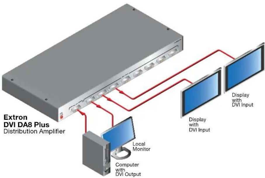
Figure 1. Typical Application for the DVI DA8 Plus
Features
EDID Minder — The EDID Minder maintains continuous EDID (Extended Display Identification Data) communication with the attached source to ensure that the DVI source powers up correctly and maintains a proper video output, even if the display is off.
EDID Lock — The last recorded EDID is saved to the input and used after a power cycle or after displays have been changed. The EDID presented to the input is not affected by power cycles or changing the output displays (even with hot-plug changes).
High resolution DVI-D input — The distribution amplifiers accept one single link DVI-D input, with a resolution range up to 1920x1200 or 1080p @ 60 Hz.
Input equalization — Input Equalization (EQ) conditions the input signals to ensure the integrity of the signals.
Pre-emphasis — This feature enables the distribution amplifier to compensate for poor signals delivered to the output devices.
DVI-D outputs — The units distribute four (DVI DA4 Plus), six (DVI DA6 Plus), or eight (DVI DA8 Plus) single link DVI-D output signals simultaneously, at resolutions up to 1920x1200 or 1080p @ 60 Hz.
External power supply — All three models are powered by an ENERGY STAR ^® qualified external 12 VDC power supply (provided with the units), which provide worldwide compatibility, low power consumption, and reduced operating costs.
Power on pin 14 — The distribution amplifiers provide a 5 VDC (250 mA) power on each output for peripheral devices.
Front panel indicator LED — The LED light on the front panel provides feedback about power status and whether an input signal is detected.
Versatile mounting options — All three units can be mounted in a rack, under a desk or set on a tabletop.
Installation
This section describes:
• Installation Overview
- Rear Panel Features
Installation Overview
All three distribution amplifiers can be mounted on tabletops, under furniture, and in racks by following these steps:
- Ensure that the input sources, the distribution amplifier and the output displays are all turned off and all power sources and signal cables are disconnected.
- Mount the unit as described in "Mounting" on page 15.
- Connect the cables (see "Rear Panel Features" on page 4).
- If required, configure the internal DIP switches to disable EDID (see page 8) from certain outputs or to activate the EDID Lock mode (see page 10).
- Plug in the power supply (see page 4).
- Turn on the display devices.
- Turn on the input devices (see "Operation" on page 7).
Rear Panel Features
The rear panels for the DVI DA4 Plus (top panel), the DVI DA6 Plus (middle panel), and DVI DA8 Plus (bottom panel) are shown below.
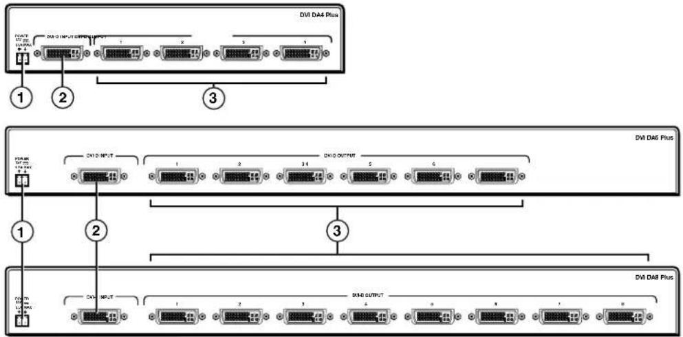
Figure 2. Rear Panel Features
① Power input — Connect the two pole, 3.5 mm captive screw connector from the power supply (provided with the unit) to this socket on the rear panel.
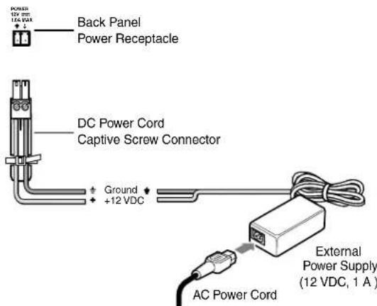
Figure 3. Power Supply Connection
The external power supply in the illustration above (12 VDC, 1 A) is for use with the DVI DA4 Plus. The DVI DA6 Plus and DVI DA8 Plus use a 12 VDC, 3 A external power supply.
CAUTION: These products are intended to be supplied by a Listed Power Unit marked "Class 2" or "LPS", rated 12 VDC, maximum 1.0 A (DVI DA4 Plus) or maximum 3.0 A (DVI DA6 Plus and DVI DA8 Plus). Always use a power supply supplied by or specified by Extron. Use of an unauthorized power supply voids all regulatory compliance certification and may cause damage to the supply and the end product.
Unless otherwise stated, the AC/DC adapters are not suitable for use in air handling spaces or in wall cavities. The power supply is to be located within the same vicinity as the Extron A/V processing equipment in an ordinary location, Pollution Degree 2, secured to the equipment rack within the dedicated closet, podium or desk.
The installation must always be in accordance with the applicable provisions of National Electrical Code ANSI/NFPA 70, article 75 and the Canadian Electrical Code part 1, section 16. The power supply shall not be permanently fixed to building structure or similar structure.
NOTE: • The length of the exposed wires in the stripping process is critical. The ideal length is 3/16 inches (5 mm). Any longer and the exposed wires may touch, causing a short circuit between them. Any shorter and the wires can be easily pulled out even if tightly fastened by the captive screws.
- Do not tin the wires. Tinned wire does not hold its shape and can become loose over time.
② Input connector — Connect a single link DVI-D source device, with a resolution range up to 1920x1200 or 1080p@60 Hz, to the female DVI-I input, using a DVI cable.
NOTE: Although these distribution amplifiers have DVI-I connectors, they are only compatible with single link DVI-D video signals.
Input EQ conditions input signals to ensure the integrity of the signals delivered to the output devices.
③ Output Connectors — Use DVI-I cables to connect up to four (DVI DA4 Plus), six (DVI DA6 Plus) or eight (DVI DA8 Plus) display devices.
NOTE: The actual signal transmission distance can vary and depends on signal resolution, cable quality, graphics card, and display used in the system.
DVI Connector Pin Assignments
The illustration below shows the pin assignments for the DVI-I connectors. See the note under input connectors for information about DVI signal compatibility.
NOTE: The DVI DA Plus series distribution amplifiers are not High-Bandwidth Digital Content Protection (HDCP) compliant.

| Pin | Signal | Pin | PinSignal | Signal | |
| 1 | TMDS data 2- | 9 | TMDS data 1- | 17 | TMDS data 0- |
| 2 | TMDS data 2+ | 10 | TMDS data 1+ | 18 | TMDS data 0+ |
| 3 | TMDS data 2/4 shield | 11 | TMDS data 1/3 shield | 19 | TMDS data 0/5 shield |
| 4 | Spare | 12 | Spare | 20 | Spare |
| 5 | Spare | 13 | Spare | 21 | Spare |
| 6 | DDC clock +5 | V | Power | 22 | TMDS clock shield |
| 7 | DDC data TM | DS | clock+Ground | 23 | |
| 8 | Spare | 16 | Hotplug detect | 24 | TMDS clock- |
Operation
This section of the guide provides information on:
- Front Panel Features
- Operation
• EDID Minder
• Disabling the EDID Minder - Troubleshooting
Front Panel Features
Figure 4 shows the front panel for the DVI DA4 Plus (top) and the front panel for the DVI DA6 Plus/DVI DA8 Plus, which are identical (bottom).
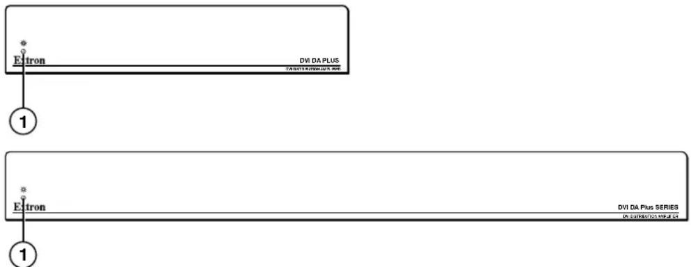
Figure 4. DVI DA Plus Series Front Panel Features
① LED indicator — This LED indicator lights amber when the unit is receiving power but no input signal. When the unit detects an input signal, the LED lights green.
Operation
Once the distribution amplifier has been installed and the cables have been connected:
- Power on the display devices.
- Power on the distribution amplifier. The LED lights amber to show that the unit is receiving power.
- Power on the input device.
EDID Minder
When a DVI video source boots up, it normally communicates with the output device using the bidirectional Extended Display Identification Data (EDID) communication protocol. The source device then produces a signal with a resolution that is compatible with the output device.
The Extron EDID Minder feature maintains continuous EDID communication with the attached source and ensures that the DVI source powers up correctly and maintains a proper video output even if the display is off, or when a new monitor is connected to the output.
In default mode, when the distribution amplifier is powered on, it automatically scans all detectable outputs, selects the device with the lowest native resolution and passes the EDID information from that device to the input device.
While the distribution amplifier remains powered on, it monitors the Hot Plug Detect (HPD) signal on each output and repeats the scan process every time a display is connected or disconnected.
If all outputs displays are removed, the EDID provided is that of the last stored display to which the distribution amplifier was connected. If no output device has previously been connected to the unit, or the unit has been through a power cycle with no displays attached, the EDID uses the factory default, reporting a native rate of 1024x768.
When the EDID Minder is in Lock mode (see page 10), the last recorded EDID is stored to the input and used after a power cycle or after the displays have been changed.
Disabling the EDID Minder
Some applications require that the distribution amplifier does not automatically read the EDID from one or more specific outputs. In those cases, the EDID Minder feature can be disabled so those specific outputs are ignored during the automatic scanning process:
- Remove and keep the screws holding the cover to the base. For the DVI DA4 Plus, there are three screws along the rear edge of the top and two screws on each side. For the DVI DA6 Plus and DVI DA8 Plus, there are four screws along the rear edge of the top and three screws along each side. Set aside the cover.
- Check the part number of the printed circuit board (outlined in yellow in figure 5 on the next page). The boards must have a part number of 20-1496-01LF and higher for the DVI DA4 Plus or 20-1497-01LF and higher for the DVI DA6 Plus or DVI DA8 Plus.
NOTE: If the part number of the board is lower than these values, you cannot deactivate the EDID Minder on your model. Replace the cover as described in step 5.
- Locate the DIP switches. There is a single bank of four switches for the DVI DA4 Plus (outlined in red in figure 5). Each switch regulates the correspondingly numbered output (1-4).
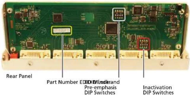
Figure 5. Printed Circuit Board for the DVI DA4 Plus
There are two banks of four switches for the DVI DA6 Plus (see figure 6) and the DVI DA8 Plus. In the bank to the left, each switch regulates the correspondingly numbered output (1-4). In the bank to the right, switches 1 and 2 correspond to outputs 5 and 6 for the DVI DA6 Plus; switches 1-4 correspond to outputs 5-8 for the DVI DA8 Plus.
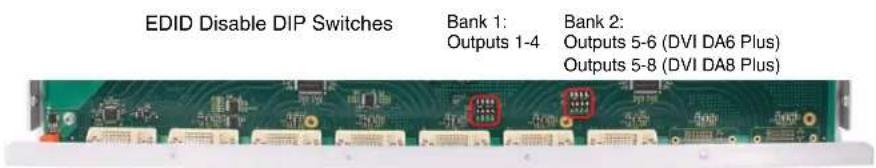
Figure 6. EDID Disable DIP Switches for the DVI DA6 Plus
-
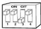
By default the switches are in the "Off" (down) position, allowing the EDID information to be read from the corresponding output. To deactivate EDID Minder for one or more outputs, move the switch for that output to the "On" (up) position. In the diagram at right, the unit will read EDID from output 3, but not from outputs 1, 2, or 4.
-
Replace the cover, using the screws that were removed in step 1.
EDID Lock
Some applications require the distribution amplifier to maintain specific EDID information. This information could be lost after power is cycled off and on or when a new output display is connected to the DVI DA Plus.
By default the EDID Lock mode DIP switch is set to "Off". In this position, when the distribution amplifier is powered off, the EDID information that was being used is erased. When the distribution amplifier is powered back on, it automatically scans all detectable outputs, selects the device with the lowest native resolution and passes the EDID information from that device to the input device. If no output devices are detected, the distribution amplifier uses the factory default EDID (1024x768 @ 60 Hz).
While the distribution amplifier remains powered on, it monitors the Hot Plug Detect (HPD) signal on each output and repeats the scan process whenever a display is connected or disconnected.
When EDID Lock feature is enabled, the last recorded EDID is saved to the input and used when the power is cycled on and off or when a new display, with a different resolution, is connected.
| Switch Position | Action on the Input |
| On (Lock) • The last recorded EDID is stored to the input. | |
| Off (Default) • After a power cycle, the DA reads EDID from all valid displays, determines the lowest resolution, and stores that to the input. | |
To enable the EDID Lock feature:
- Remove and keep the screws holding the cover to the base. For the DVI DA4 Plus, there are three screws along the rear edge of the top and two screws on each side. For the DVI DA6 Plus and DVI DA8 Plus, there are four screws along the rear edge of the top and three screws along each side. Set aside the cover.
- Check the part number of the printed circuit board (see figure 5). The boards must have a part number of 20-1667-01LF and higher for the DVI DA4 Plus or 20-1683-02LF and higher for the DVI DA6 Plus or DVI DA8 Plus.
NOTE: If the part number of the board is lower than these values, the EDID Lock feature is not available on your model. Replace the cover as described in step 5.
-
Locate the Pre-emphasis and EDID Lock DIP switches. Figure 5, shows the switches for the DVI DA4 Plus. The DVI DA6 Plus and DVI DA8 Plus have an identical block of DIP switches in a similar position on the circuit board. The EDID Lock DIP switch (number 2) is labeled EDID Mode.
-
By default, the EDID Mode DIP switch is in the down (disabled) position, allowing for normal operation. To enable the EDID Lock feature, toggle the switch to the up position.
NOTE: Before enabling the EDID Lock feature, be sure the desired EDID is currently being used.
- Replace the cover, using the screws that were removed in step 1.
Pre-emphasis
Pre-emphasis compensates for long cable runs, distortion, and pixelation on the distribution amplifier outputs. To enable pre-emphasis:
- Remove and keep the screws holding the cover to the base. For the DVI DA4 Plus, there are three screws along the rear edge of the top and two screws on each side. For the DVI DA6 Plus and DVI DA8 Plus, there are four screws along the rear edge of the top and three screws along each side. Set aside the cover.
- Check the part number of the printed circuit board (see figure 5). The boards must have a part number of 20-1667-01LF and higher for the DVI DA4 Plus or 20-1683-02LF and higher for the DVI DA6 Plus or DVI DA8 Plus.
NOTE: If the part number of the board is lower than these values, you cannot activate pre-emphasis on your model. Replace the cover as described in step 5.
- Locate the Pre-emphasis DIP switch (number 1), which is labeled Preemph.
- By default, the Pre-emphasis DIP switch is in the down (disabled) position. To enable pre-emphasis, toggle the switch to the up position.
- Replace the cover, using the screws that were removed in step 1.
Troubleshooting
No output signal — Check that the front panel LED is lit (amber shows that the unit is receiving power, green shows that it is also receiving an input signal). If LED is not lit, check the power supply (page 4) and the video input connections (see page 5).
No output signal or poor quality signal — Check the integrity of the cabling from the source device to the distribution amplifier and from the distribution amplifier to each of the display devices.
- DVI signals run at very high frequency and poor connections can cause degradation or loss of the signal, or jitter.
- Signal transmission distance can vary greatly and depends on signal resolution, cable type, cable quality, graphics card and the display used in the system.
• Use only cable that is designed for DVI signals. - Limit or avoid the use of adapters or couplers.
- Enable the Pre-emphasis feature
Display device displays a flashing black or blue screen, snow or other distortion — A device that is not HDCP compliant may be receiving HDCP-encrypted signals. The DVI DA Plus series distribution amplifiers are not HDCP compliant.
Signal on some displays but not others — Reboot the source device. When the source device boots up, the EDID handling feature ensures that the output resolution of the source device matches the requirements of the display device with the lowest resolution.
If an additional display device is added, which requires an even lower resolution, the image will not be displayed correctly on that monitor until the source device is shut down and rebooted. At that time, EDID handling ensures that the output resolution of the source device is recalibrated to meet the needs of the additional display device.
NOTE: For EDID handling to work correctly, you must disable the EDID Lock feature for all outputs (see "EDID Lock" on page 10).
Specifications
Video
Maximum data rate.... 4.95 Gbps (1.65 Gbps per color)
Maximum pixel clock.... 165 MHz
Resolution range Up to 1920x1200 or 1080p @ 60 Hz
Formats.... RGB and YCbCr digital video
Standards...... DVI 1.0, HDMI 1.2
Video input
Number/signal type 1 single link DVI-D (or HDMI*)
Connectors 1 female DVI-I
Video output
Number/signal type 4, 6, or 8 (depending on model) single link DVI-D (or HDMI*)
Connectors 4, 6, or 8 female DVI-I
NOTE: *Appropriate DVI-D to HDMI cables or adapters are required for HDMI signal input/output.
General
External power supply 100 VAC to 240 VAC, 50-60 Hz, external; to 12 VDC, regulated
DVI DA4 Plus.... 1 A
DVI DA6 Plus, DVI DA8 Plus..... 3 A
Power input requirements ..... 12 VDC
DVI DA4 Plus 1.0 A (max.)
DVI DA6 Plus, DVI DA8 Plus ..... 1.5 A (max.)
Temperature/humidity ...... Storage: -40 to +158 °F (-40 to +70 °C) / 10% to 90%, noncondensing
Operating: +32 to +122 °F (0 to +50 °C) / 10% to 90%, noncondensing
Cooling...... Convection, no vents
Mounting
Rack mount .... Yes, with optional rack (DVI DA4 Plus) or included brackets (DVI DA6 or 8 Plus)
Furniture mount .... Yes, with optional under-desk mounting kit
Enclosure type.... Metal
Enclosure dimensions
DVI DA4 Plus 1.75" H x 8.75" W x 3.0" D (1U high, half rack wide)
(4.4 cm H x 22.2 cm W x 7.6 cm D)
(Depth excludes connectors.)
DVI DA6 Plus, DVI DA8 Plus..... 1.75" H x 17.5" W x 8.5" D (1U high, full rack wide)
(4.4 cm H x 44.4 cm W x 21.6 cm D)
(Depth excludes connectors.)
Product weight.... 2.8 lbs (1.3 kg)
Shipping weight 5 lbs (3 kg)
Vibration.... ISTA 1A in carton (International Safe Transit Association)
Regulatory compliance
Safety CE, c-UL, UL
EMI/EMC CE, C-tick, FCC Class A, ICES, VCCI
MTBF 30,000 hours
Warranty 3 years parts and labor
NOTE: All nominal levels are at ±10%
Specifications are subject to change without notice.
Reference Information
Included Parts
| Description Part Number | |
| DVI DA4 Plus 60-931-21 | |
| or DVI DA6 Plus 60-932-21 | |
| or DVI DA8 Plus 60-933-21 | |
| 12 VDC, 1 A desktop power supply (for use with DVI DA4 Plus) 70-775-01 | |
| or 12 VDC, 3 A desktop power supply (for use with DVI DA6 Plus and DVI DA8 Plus) | 70-380-01 |
| (1) IEC cord | |
| (4) Rubber feet (not attached) | |
| MBD 149 rack mount kit (DVI DA6 Plus and DVI DA8 Plus only) 70-077-03 | |
| DVI DA Plus Series Setup Guide |
Optional Accessories
| Description Part Number | |
| RSF 123 (3.5 inches deep, 1U rack shelf kit) 60-190-20RSB 123 (3.5 inches deep, 1U basic rack shelf) 60-604-21RSU 126 (6 inches deep, 1U rack shelf kit) 60-190-10RSB 126 (6 inches deep, 1U basic rack shelf) 60-604-11RSU 129 (9.5 inches deep, 1U rack shelf kit) 60-190-01RSB 129 (9.5 inches deep, 1U basic rack shelf) 60-604-02 | |
| MBU 149 under desk mounting kit (for DVI DA6 Plus and DVI DA8 Plus)MBU 123 under desk mounting kit (for DVI DA4 Plus only) 70-212-01DVID SL series (3, 6 or 15 feet single link DVI-D male to male patch cables)IN9700 series (6, 25, 35, 50 or 75 feet single link DVI-D male to male long distance extension cables) | 70-222-0126-585-0x26-584-0x |
Mounting
This section outlines the various mounting options available for the DVI DA Plus series of distribution amplifiers:
- Tabletop Placement
- Rack Mounting
• Under-desk Mounting
Tabletop Placement
Attach the four provided rubber feet to the bottom of the unit and place it in any convenient location.
Rack Mounting
UL Guidelines for Rack Mounting
The following Underwriters Laboratories (UL) guidelines are relevant to the safe installation of these products in a rack:
Elevated operating ambient temperature — If the unit is installed in a closed or multi-unit rack assembly, the operating ambient temperature of the rack environment may be greater than room ambient temperature. Therefore, install the equipment in an environment compatible with the maximum ambient temperature (Tma: +122 °F, +50 °C) specified by Extron.
Reduced air flow — Install the equipment in the rack so that the equipment gets adequate air flow for safe operation.
Mechanical loading — Mount the equipment in the rack so that uneven mechanical loading does not create a hazardous condition.
Circuit overloading — Connect the equipment to the supply circuit and consider the effect that circuit overloading might have on overcurrent protection and supply wiring. Give appropriate consideration to the equipment nameplate ratings when addressing this concern.
Reliable earthing (grounding) — Maintain reliable grounding of rack-mounted equipment. Pay particular attention to supply connections other than direct connections to the branch circuit (such as the use of power strips).
Rack Mounting the DVI DA4 Plus
The DVI DA4 Plus can be mounted a range of (optional) rack shelves (see Optional Parts on page 14). To mount the units, follow the instructions provided with the rack mounting kit.
Rack Mounting the DVI DA6 Plus and DVI DA8 Plus
The DVI DA6 Plus and DVI DA8 Plus distribution amplifiers can be mounted using the Extron MBD 149 rack mount kit (provided) following the instructions provided with the MBD 149.
Under-desk Mounting
Mount the DVI DA6 Plus or DVI DA8 Plus under furniture, using the optional Extron MBU 149 under-desk mounting kit (part number 70-222-01). Mount the DVI DA4 Plus using the optional Extron MBU 123 under-desk mounting kit (part number 70-212-01). Follow the instructions provided with the appropriate kit.
Extron® Warranty
Extron Electronics warrants this product against defects in materials and workmanship for a period of three years from the date of purchase. In the event of malfunction during the warranty period attributable directly to faulty workmanship and/or materials, Extron Electronics will, at its option, repair or replace said products or components, to whatever extent it shall deem necessary to restore said product to proper operating condition, provided that it is returned within the warranty period, with proof of purchase and description of malfunction to:
USA, Canada, South America, and Central America:
Extron Electronics
1001 East Ball Road
Anaheim, CA 92805
U.S.A.
Japan:
Extron Electronics, Japan
Kyodo Building, 16 Ichibancho
Chiyoda-ku, Tokyo 102-0082
Japan
Europe, Africa, and the Middle East:
Extron Europe
Hanzeboulevard 10
3825 PH Amersfoort
The Netherlands
China:
Extron China
686 Ronghua Road
Songjiang District
Shanghai 201611
China
Asia:
Extron Asia
135 Joo Seng Road, #04-01
PM Industrial Bldg.
Singapore 368363
Singapore
Middle East:
Extron Middle East
Dubai Airport Free Zone
F12, PO Box 293666
United Arab Emirates, Dubai
This Limited Warranty does not apply if the fault has been caused by misuse, improper handling care, electrical or mechanical abuse, abnormal operating conditions, or modifications were made to the product that were not authorized by Extron.
NOTE: If a product is defective, please call Extron and ask for an Application Engineer to receive an RA (Return Authorization) number. This will begin the repair process.
USA: (714) 491-1500
Asia: +65.6383.4400
Europe: +31.33.453.4040
Japan: +81.3.3511.7655
Units must be returned insured, with shipping charges prepaid. If not insured, you assume the risk of loss or damage during shipment. Returned units must include the serial number and a description of the problem, as well as the name of the person to contact in case there are any questions.
Extron Electronics makes no further warranties either expressed or implied with respect to the product and its quality, performance, merchantability, or fitness for any particular use. In no event will Extron Electronics be liable for direct, indirect, or consequential damages resulting from any defect in this product even if Extron Electronics has been advised of such damage.
Please note that laws vary from state to state and country to country, and that some provisions of this warranty may not apply to you.
Installation Checklist
☐ Ensure that the input sources, the distribution amplifier and the output displays are all turned off and all power sources and signal cables are disconnected.
☐ Mount the unit as described in "Mounting", (see page 15).
☐ Connect the cables (see "Rear Panel Features", on page 4).
☐ If required, configure the internal DIP switches to disable EDID (see page 8) from certain outputs, to activate the EDID Lock mode (see page 10), or to enable pre-emphasis (see page 11).
☐ Plug in the power supply (see page 4).
☐ Turn on the display devices.
☐ Turn on the input devices (see "Operation", on page 7).
| Extron USA - West Headquarters | Extron USA - East | Extron Europe | Extron Asia | Extron Japan | Extron China | Extron Middle East |
| +800.633.9876Inside USA/Canada Only | +800.633.9876Inside USA/Canada Only | +800.3987.6673Inside Europe Only | +800.7339.8766Inside Asia Only | +81.3.3511.7655 | +400.883.1568Inside China Only | +971.4.2991800 |
| +1.714.491.1500+1.714.491.1517 FAX | +1.919.863.1794+1.919.863.1797 FAX | +31.33.453.4040+31.33.453.4050 FAX | +65.6383.4400+65.6383.4664 FAX | +81.3.3511.7656 FAX | +86.21.3760.1568+86.21.3760.1566 FAX | +971.4.2991880 FAX |