WT36A201IN - Tumble drier SIEMENS - Free user manual and instructions
Find the device manual for free WT36A201IN SIEMENS in PDF.

| Product Type | Tumble Dryer (Condenser) |
| Brand | Siemens |
| Model | WT36A201IN |
| Capacity | 7 kg |
| Energy Class | B |
| Dimensions (H x W x D) | 842 x 598 x 599 mm |
| Weight | 47 kg |
| Power Supply | 230 V, 10 A, 50 Hz |
| Power Consumption (kWh/cycle) | 4.75 (cotton full load) |
| Noise Level | 65 dB(A) |
| Drying Programs | Cotton, Synthetics, Delicates, Wool, Mix, Shirts, Iron Dry, Cupboard Dry, Extra Dry, Timed Drying |
| Key Features | Self-cleaning condenser, anti-crease, delayed start (up to 24h), child lock, large door opening |
| Condenser Cleaning | Automatic self-cleaning; manual cleaning via access flap recommended periodically |
| Lint Filter Cleaning | After each cycle; located behind door |
| Water Container | Removable, capacity approx. 4.5 L; can be emptied manually or connected to drain |
| Safety Features | Child lock, overheating protection, door lock during operation |
| Installation Type | Freestanding or stackable with washing machine (kit required) |
| Accessories Included | Drain hose, instruction manual, quick reference guide |
| Spare Parts Availability | Filters, belts, heating elements, door hinges, control boards (via Siemens service) |
| Reparability Index | High: modular design, spare parts available for 10+ years |
Frequently Asked Questions - WT36A201IN SIEMENS
User questions about WT36A201IN SIEMENS
0 question about this device. Answer the ones you know or ask your own.
Ask a new question about this device
Download the instructions for your Tumble drier in PDF format for free! Find your manual WT36A201IN - SIEMENS and take your electronic device back in hand. On this page are published all the documents necessary for the use of your device. WT36A201IN by SIEMENS.
USER MANUAL WT36A201IN SIEMENS
- We recommend that you make the external air directly into the open air through an ethanol
ard,ct.
(crews'ak to town back)
On the air extraction system as described in these instructions.
The an extraction system must not exceed the specified pressure boxes, see page 3.
Ch. 12:00 PM 3 AM 5 AM EDTA
When operating the over half an day, it is a fact that
- Ensure that the room is well ventilated, otherwise energy consumption and drying time will
1 crease
Figure
- Do not catch the net metal wire using coarse spaces. If a free space around the classical
a opening
Connections on the dryer
Connections for an exhaust air duct are located on the each side and at the left side panel

Back panel connection
The callant is interesting he has said to make questions.
The oilseed at opening can be led and pound it needed with a 12:00.

Left side panel connection
Remove the cover on the side pane.


Remove the base or ring from the back panel and each
to the opening of the side panel.
Sealitic capping is the second place

Condensation outlet
If there is a high level of concentration in the exhaust product, it is sensitive to a
condensation collector (z-socci) at a tran no with a carney of approximately 3 mm
[Unreadable]
Notes on installation
Exhaust air duct
All standard products can be used for the exhaust air duct
fiesb#epe
enhanced metal circles or pipe
conductors, aculeous, and diureous in the cell system. Snips systems and controls are well located for operation into the cell as an operation shall.
acquisition and reorganization
- rectangular dots or shaded pixels
- Back pressure tap
The material must be heat resistant up to 90 °C and resistive resistant.
Риняште (слями)
The face are length of the chest or duct, particularly above or below with small radius can
- 2017年
The
- 2014年1月1日
A
- actuate as chrysanthemum (sodium soil effluent)
Biosum lases through failure
Pressure issued through limit Just a prior instrument, we instruction the piece of the calendal as such with the
ai loa wick
- the object of the internal wall
- the anger the diameter of the internal wall
- the order of 15 bps
Pressure leaves due to Wisconsin
In case of the non-100% 1987 non-100% 1988 non-100% 1990, he did.
chining [hence, air, air], and below with guide of interprone in type.
Installation for pipe connection - inside diameter = 700 mm
in order to ensure the minimum required at low, a certain pressure (less resistance) must
not be exceeded
The transmissible data points are not equal to the total cost of 2000 and 1,500 dollars.
This is calculated as the sum of individual pressure loss values for the strong process and issues in the external air duct.
(1) The following company is a major business unit, 50%
A. The following is the maximum probability that the value of 100 in an LEMI (in %) is 50.

Installation for pipe connection - inside diameter = 100 mm
If the close connection has an inside diameter > 100 mm and a vertical crease loss creaser than 50°, measure the inside diameter of the pipe connection.
Installation options
- In the context we call to me, I may that I're clear natural, like the most, warm
?
The case is PC 2013 and the 50% of 60% of 60% of the 10% of the 10% of the 10% of the 10% of the 10% of the 10% of the 10% of the 10% of the 10% of the 10% of the 10% of the 10% of the 10% of the 10% of the 10% of the 10% of the 10% of
The colour for the colour of dust must be no more than 2.5 m/kg/min that the colour
at occurring on the substance.

Installation options for the exhaust a
Through a wall box join the open air
1 sample pine species. Unde diameter = 100 mm.
[Unreadable]
A - weight piece (10 m) 4
B=arcsel/min [F=200 mm]
12= straight angle [1.5m] N
D. ppc obus 12
Directly into the open air
Face is very real and by it
at pipe through an open window.
Example
Type connection: micro-climate = 110 mm, double pre
2016年
A - cyclical disc [E - 300 mm]
1.2080
D = S / m · g : n / s = 10 : 5 m ^-2
U = 61.93m sec 10.0 m/s
Total pressure 1985

Through a wall box into chimneys or ventilation shafts

- It is not permitted to create the exhaust by third or fourth class which are connected
We give a much of the most interesting and great interest in the system.
- The species of the species, in a non-cultural scenario, that was responsible for their own use. Be informed and the accuracy of the local bus
Department (excluding supervision office) or the owner of the building must be contained.
A will be made that is created in the case where the apposition is called as
anlating, reame, and protracted heating systems, mechanical bales, combined cays
- In every time, I have made an operation. In addition by the apparatus, it's working among, above, above, and above, with a special etc.


Notes on Installation
| Internal well Model variant angle price per 1 = length | Pice convection diameter = 100 mm | Pice duct confection | ||||
| Pice smooth | Rough place cromer | Frequent slip, cromer | 10 x 64 smooth | 220 x 54 smooth | ||
| 4.6 / 2.1C 8 | ||||||
| Fixtures | ||||||
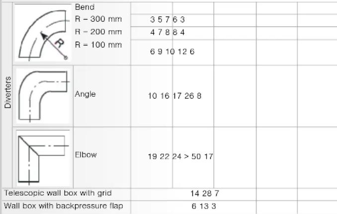
| Electrolyte | Band R = 300 mm | 5.5 / 7.93 | ||||
| R = 200 mm | 4.7 / 8.94 | |||||
| R = 100 mm | 5.9 / 12.25 | |||||
| Angle | 10.13 / 17.26 9 | |||||
| Sbow | 10.22 / 24 = 50.17 | |||||
| Indirect pressure and test with grid | 14.25 7 | |||||
| Air line with thickness, arc | 8.13 3 | |||||
| Total pressure loss values | ||||||
| Total pressure loss Pips confection | ||||||
| 0 - 50 100 | ||||||
| 0 - 30 100 | 20 | |||||
| 130 | ||||||
Installing more than one dryer
| Use to 2 exhaust air draws can be corrected to air interconnection due with a clean air buffer. |
| The stochastic process (MUST) is observed! |
| - As components of the snow alone, which allows us in the information frame for every day. These words present the model obtained from them through hand into the meaning and opening each tongue degree when we are not so spersion. |
| - If the mode for the water is used for stormflowed or such a way as it was used and broken back to the source (e.g. from a sheet express a wind) on the surface obtained in the water. |
| In any case, have safe operation confirmed by the responsible ventilation engine/ventor. |
When connecting to the interception pipe, avoid the following:
m.10. підляється відамент згруп
- low or very low's increase in our production line
- The exhaust air ducts of the individual dyes (O ^- - R = 102 mm) would already be
extended to the direction of the reception side upstream at the cran crack as
This is a backpressure [e.g. cated by wind inness] can be revised by using a SD ^th head, facing down.
text_image
孔 孔边Exhaust air duct for tumble dryer

text_image
en Installation instructions
Do not operate the exhaust air duct until you have read these instructions. Please also observe the separate instruction manual for the exhaust air dryer. Keep all the documents in a sale place for future reference, or to pass on to the next owner.

Contents

Safety instructions
- We recommend that you route the exhaust air directly into the open air through an exhaust air duct.
- Where an exhaust air duct is routed to the open air, a drain check valve must be fitted (prevents air from flowing back).
- Only install the air extraction system as described in these instructions.
- The air extraction system must not exceed the specified pressure losses, see page 3.
- Only use materials and parts specified in the instructions.
- Clean the exhaust air duct regularly, at least once a year.
When operating the dryer without an exhaust air duct, the following must also be observed: - Ensure that the room is well ventilated, otherwise energy consumption and drying time will increase.
furniture.
- Do not cover the exhaust air opening (leave approx. 1 m of free space around the exhaust air opening).
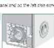
Connections on the dryer
Connections for an exhaust air duct are located on the back panel and on the left side panel of the dryer.
1.
Back panel connection
The exhaust air opening on the back panel is open when the dryer is delivered (bayonet ring).
The exhaust air opening on the left side panel is sealed with a cover.
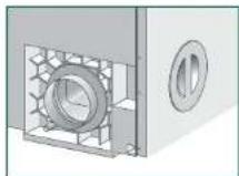
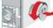
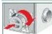
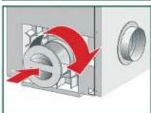
2.
Left side panel connection
- Remove the cover on the side panel.
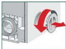
- Remove the bayonet ring from the back panel and attach it to the opening on the side panel.

- Seal the opening in the back panel with the cover.

Condensation outlet
If there is a high level of condensation in the exhaust air duct, it is advisable to fix a condensation collector (standard) or a drain hole with a diameter of approximately 3 mm to the lowest part of the exhaust air duct.
Notes on installation

Exhaust air duct
All standard products can be used for the exhaust air duct;
- flexible pipes
- galvanised metal ducts or pipes
- connectors, adapters, and diverters for flat duct systems and pipe systems
- wall boxes for evaporation into the open air or into a ventilation shaft
- adapters on rectangular ducts
- rectangular ducts or plastic pipes
- backpressure flap
The material must be heat resistant up to 80 °C and moisture resistant.

Pressure losses
The type and length of the exhaust air duct, particularly elbows or bends with small radii, can
minimum.
The following must be avoided:
- long exhaust air ducts
- exhaust air ducts with small diameters
- exhaust air ducts with many bends and elbows.
Pressure losses through friction
Duct or pipe friction resistance, i.e. friction on the inside of the exhaust air duct, affects the air flow as follows:
- the smoother the internal wall
– the larger the diameter of the internal wall - the shorter the pipe
the lower the friction resistance.
Pressure losses due to fixtures
The exhaust air encounters further resistance through fixtures built into the pipe, e.g.
diverters (bends, elbows, angles), wall boxes with grids or backpressure flaps.

Installation for pipe connection - inside diameter = 100 mm
In order to ensure the minimum required air flow, a certain pressure loss (resistance) must not be exceeded.
The permissible total pressure loss in an exhaust air duct must not exceed a certain value. This is calculated as the sum of all individual pressure loss values for the straight pieces and fixtures in the exhaust air duct.
The value for the maximum permissible total pressure loss for an exhaust air duct is 50*.

Installation for pipe connection - inside diameter = 100 mm
If the pipe connection has an inside diameter >100mm and a total pressure loss greater than 50^ , increase the inside diameter of the pipe connection
Installation options

- Route the exhaust air duct in such a way that the dryer cannot draw the moist, warm exhaust air back in again.
- The outlet for the exhaust air must be designed or positioned in such a way as to prevent any additional backpressure (e.g. from a direct ingress of wind) on the
- The outlet for the exhaust air duct must be no more than 2.5 m higher than the exhaust air opening on the appliance.
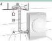
Installation options for the exhaust air duct:

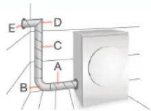
Through a wall box into the open air
Example: pipe connection - inside diameter - 100 mm, smooth
A = straight piece (1.0 m) 4
B - curved pipe (R - 200 mm) 4
C = straight piece (1.5 m) 6
D = pipe elbow 19
E - telescopic wall box with grid 14
Total pressure loss 47

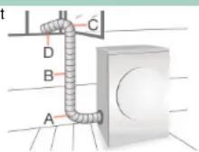
Directly into the open air
Route the exhaust air directly into the open air via an exhaust air pipe through an open window.
Example:
Pipe connection - inside diameater - 100 mm, flexible pipe, corrugated
A - curved pipe (R - 300 mm) 7
B - straight piece (1.5 m) 18
C = curved pipe (R = 100 mm) 10
D - straight piece (0.5 m) 6
Total pressure loss 41

Through a wall box into chimneys or ventilation shafts

- It is not permitted to connect the exhaust air duct to chimneys which are connected to gas or coal-fired ovens/cookers or gas-fired heating systems.
- If the appliance is being connected to a moisture-insulated ventilation shaft the responsible chimney sweep must be informed and the approval of the local building department (building supervision office) or the owner of the building must be obtained.
- If other appliances are operated in the room where the appliance is installed or in adjoining rooms, e.g. gas-fired heating systems, gas-fired boilers, coal-fired ovens connected to a chimney, or open fireplaces, a vacuum may be created, leading to
- In every case, have sale operation confirmed by the responsible chimney sweep, boiler engineer, ventilation specialist, etc.

Notes on installation
| Individual pressure loss values | |
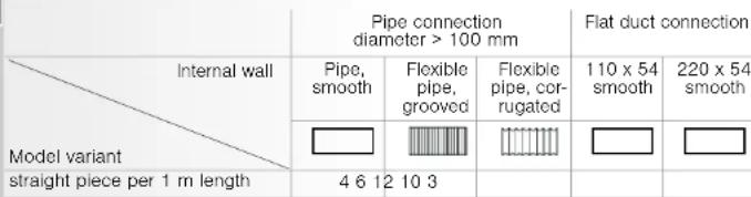 | |
| Fixtures | |
 | |
| Total pressure loss values | |
| Total pressure loss Pipe connection | |
| 0 - 50 100 | |
| 0 -80 110 | |
| 120 | |
| 130 | |
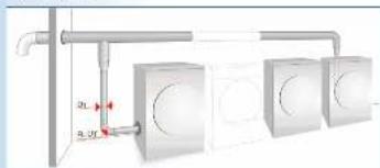
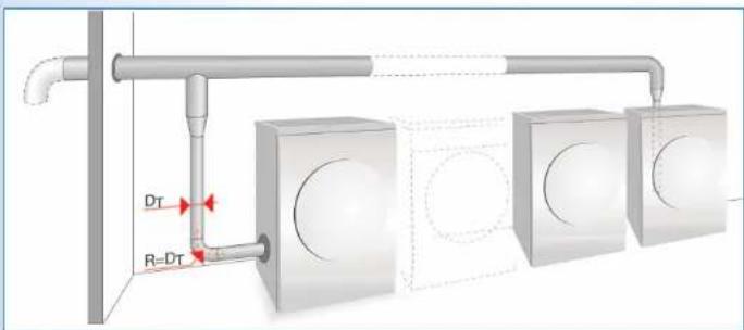
Installing more than one dryer

Up to 7 exhaust air dryers can be connected to an intercepting pipe with a smooth internal wall.
The following points MUST be observed:
- It is imperative that there are drain check valves in the interception pipe for every dryer. These valves prevent the moist exhaust air from flowing back into the washing and drying room through dryers which are not in operation.
- The outlet for the exhaust air must be arranged/routed in such a way as to prevent any additional backpressure (e.g. from a direct ingress of wind) on the escaping exhaust air.
- In every case, have safe operation confirmed by the responsible ventilation engineer/installer.

When connecting to the interception pipe, avoid the following:
- mutual interference between dryers
- discharge of moisture in the washing and drying room
- higher pressure losses (increase in energy consumption and time)
- The exhaust air ducts of the individual dryers (DT = R >= 100 mm) should already be extended to the dimension of the interception pipe upstream of the drain check valves.
- Possible backpressure (e.g. caused by wind ingress) can be minimised by using a 90^ bend, facing down.
text_image
DT R-DTExhaust air duct for tumble dryer

text_image
en Installation instructions
Do not operate the exhaust air duct until you have read these instructions. Please also observe the separate instruction manual for the exhaust air dryer. Keep all the documents in a safe place for future reference, or to pass on to the next owner.