
8585 - Printer ZEBRA - Free user manual and instructions
Find the device manual for free 8585 ZEBRA in PDF.


| Product Type | Vehicle-Mount Computer (Rugged Industrial Terminal) |
| Model | Zebra 8585 |
| Dimensions (W x H x D) | 285 x 230 x 79.5 mm (10.4" display model) |
| Weight | Approx. 2.8 kg |
| Display | 10.4" SVGA, 400 cd/m², resistive 5-wire touchscreen with brightness adjustment |
| CPU | AMD G-T40R 1.0 GHz (512 kB L2 cache) |
| RAM | 2 GB DDR3 |
| Storage | Up to 64 GB SLC Flash |
| Operating System | Windows Embedded Standard 7 or Windows 7 Professional (32/64-bit) |
| Power Supply | DC power pack, galvanically isolated |
| Input Voltage (Nominal) | 12/24 VDC (range 9-36 V) or 24/48 VDC (range 18-60 V) |
| Power Consumption | Typically 20 W, standby 1 W |
| Interfaces | 2 x USB 2.0 host, 1 x USB 2.0 service (under antenna cap), COM1 RS-232 (optional 5V), Ethernet 10/100/1000, VGA |
| Wireless | WLAN 802.11a/b/g/n (internal PCIe MiniCard) |
| Protection Class | IP65, IP66, IP67 (with cable cover installed) |
| Operating Temperature | -30°C to +50°C |
| Storage Temperature | -30°C to +65°C |
| Relative Humidity | 10% to 90% @ 40°C non-condensing |
| Mounting | VESA holes, bracket mount for vehicle console, desk, wall, or roof |
| Special Features | Passive cooling, automatic switch-off (ignition controlled), configurable front keys, touchscreen with stylus support |
| Accessories | USB keyboard, SMALL keyboard (IP65), 24-key keypad, scanner bracket, mouse, USB stick, recovery stick, microphone voice kit |
| Maintenance | Clean housing with damp cloth; touchscreen with neutral detergent or isopropyl alcohol; avoid solvents |
| Safety | CE, FCC Class B, RTTE, China Class A; SELV power; use only with approved accessories |
Frequently Asked Questions - 8585 ZEBRA
User questions about 8585 ZEBRA
0 question about this device. Answer the ones you know or ask your own.
Ask a new question about this device
Download the instructions for your Printer in PDF format for free! Find your manual 8585 - ZEBRA and take your electronic device back in hand. On this page are published all the documents necessary for the use of your device. 8585 by ZEBRA.
USER MANUAL 8585 ZEBRA
VEHICLE-MOUNT COMPUTERS
(Windows® Embedded Standard 7 & Windows 7 Professional)
USER GUIDE
8585/8595 VEHICLE-MOUNT COMPUTERS USER GUIDE
8000240-001
Revision A
July 2015
Copyright
Zebra and the stylized Zebra head are trademarks of ZIH Corp., registered in many jurisdictions worldwide. All other trademarks are the property of their respective owners.
© 2015 ZIH Corp and/or its affiliates. All rights reserved.
Disclaimer
Every effort has been made to make this material complete, accurate, and up-to-date. In addition, changes are periodically incorporated into new editions of the publication.
We reserve the right to make improvements and/or changes in the product(s) and/or the program(s) described in this document without notice, and shall not be responsible for any damages including, but not limited to, consequential damages, caused by reliance on the material presented.
Zebra, the Zebra logo, Workabout Pro4 and the names of other products and services provided by Zebra are trademarks of Zebra.
Windows® and the Windows Logo are trademarks or registered trademarks of Microsoft Corporation in the United States and/or other countries.

Bluetooth
The Bluetooth® word mark and logos are owned by Bluetooth SIG, Inc. and any use of such marks by Zebra is under license.
All trademarks used herein are the property of their respective owners.
Revision History
Changes to the original guide are listed below:
| Change Date Description | ||
| -001 Rev A | 057/2015 | Operating system updates. |
TABLE OF CONTENTS
Overview of the 8585 and 8595 Vehicle-Mount Computers.... vii
Device Models vii
Scope of Delivery...... viii
Packaging...... viii
Removing the Protective Film from the Display.... viii
Returning Your Device ix
About the 8585 / 8595 Vehicle-Mount Computer User Manual.... ix
Text Conventions ...... x
Chapter 1: Approvals and Basic Safety Guidelines
Always Install, Operate, and Maintain the Unit Properly.... 1-1
Safety....1-1
Intended Usage....1-1
Initial Operation of the Device....1-2
Power Supply....1-3
External Devices 1-3
Repairs Only 1-4
CE Marking 1-4
RTTE Directive 1999/5/EC....1-4
Special Rule/Restriction 1-5
Regulatory Summary 1-5
FCC User Information 1-5
Declaration of the Federal Communications Commission 1-5
Transmission of Radio Frequencies.... 1-5
Country Roaming 1-6
Declaration of Conformity 1-6
Regulatory Information for China....1-6
Class A Product Warning 1-6
Chinese UM URL 1-6
Quality Certificate in Chinese when the Factory has ISO 9001 Certification ....1-7
Chapter 2: Basic Operation
Removing the Protective Film from the Display.... 2-1
Zebra Config: Front Keys, WLAN, Automatic Switch-off.... 2-1
WLAN Settings 2-2
Radio Performance....2-2
Antenna Solutions for Use in Germany....2-3
Laird Connection Manager for WLAN Configuration 2-3
Admin Password 2-4
Protecting the TFT Display from the Memory Effect 2-4
Connectors 2-5
Overview of External Connectors....2-5
Adaptor Cables....2-5
DC Voltage Supply Connector....2-6
Connecting External Devices.... 2-7
Powering Up the 8585 2-7
Powering Down the 8585....2-8
Chapter 3: Installing the Computer
Overview 3-1
Follow and Retain the Mounting Instructions.... 3-1
Mechanical Dynamic Loading 3-1
Cooling Through the Supply of Fresh Air 3-1
Power Supply 3-2
Vehicle Applications (such as forklifts) 3-2
Electrical Installation....3-2
Wiring Vehicle Power to the 8585/8595 3-3
Position of the 8585 in the Vehicle 3-4
Overview of the Assembly Steps....3-4
Cable Cover (splash guard) 3-5
Strain Relief 3-5
Minimum Distance to WLAN Antenna 3-5
Antenna Cap and Service USB Interface 3-5
Chapter 4: Operation
Touchscreen 4-1
Construction Type and Resistance....4-1
Operation 4-1
Cleaning....4-2
Touch for MS Windows Embedded Standard 7 4-2
Installation....4-2
Calibration....4-2
Front Keys and LEDs 4-3
Power Key 4-3
Manual Brightness Control 4-3
LEDs 4-3
Special Keys 4-4
Shift Key 4-4
Operating States 4-4
Operating System 4-4
Pre-installed on Flash....4-5
Installing on Flash....4-5
Special Features of the Operating Systems....4-5
Serial Port 4-5
COM1 as a Power Supply....4-5
Serial Port Printers 4-5
Serial Port Bar Code Scanners 4-5
Tips and Tricks 4-6
Internal Devices 4-6
Chipset....4-6
VGA Adaptor 4-6
Onboard Sound Controller 4-6
Network Adaptor (10/100/1000)......4-6
Problems with Data Transmission via LAN/Ethernet 4-7
Automatic Switch-off....4-7
Modes of Operation....4-7
Automatic Switch-off Process 4-7
Configuration with Zebra Config Program.... 4-8
Chapter 5: Accessories
Keyboard....5-1
SMALL Keyboard 5-1
24-key Keypad....5-1
Scanner Bracket 5-2
Mouse 5-2
USB Stick 5-2
USB Recovery Stick....5-2
Scanners....5-2
WLAN Card (PCIe MiniCard) 5-3
Microphone (Voice Kit)....5-3
Chapter 6: Maintenance and Troubleshooting
Maintenance 6-1
Cleaning the Housing 6-1
Touchscreen Cleaning....6-1
Troubleshooting 6-1
Data Transmission via LAN/Ethernet 6-1
Images for AMD Devices are not Compatible with Intel Devices 6-2
8585/8595 AMD: Switch Off/Restart 6-2
Common Mistakes in Usage 6-2
Intel Images are not Compatible with AMD Devices....6-2
Power Supply 6-2
Powering Up/Down....6-2
Cable Cover....6-2
Mounting/Installation....6-2
Mobile Application on Vehicles....6-3
Using the Touchscreen....6-3
Cleaning the Touchscreen....6-3
Disposal 6-3
Chapter 7: Device Description and Technical Specifications
General 7-1
Device Models 7-2
Abbreviations Used for Devices and Accessories 7-2
Device/Type identification 7-2
Device Type Plate....7-2
Technical specifications 7-3
Mechanical (8585/8595)....7-3
8585/8595 AMD: CPU, Cache, RAM (Motherboard) 7-3
Operating System (Optional) for 8585/8595 AMD 7-4
Serial Port 7-4
USB-connection, Service USB 7-4
Touchscreen Interface 7-4
8585/8595 AMD: Network Interface 7-4
Power Supply....7-5
Power Supply Fuses 7-5
Ambient Conditions 7-6
Dimensions 8585/10 7-6
Front View....7-6
Side View....7-8
Top View 7-9
VESA Drill Holes....7-10
Approvals 7-10
Appendix A: Zebra Config Program
Basic Safety Guidelines....A-1
Overview of Functions ...... A-1
Installation....A-3
System Requirements....A-3
Pre-installed on Zebra Computers A-3
Subsequent Installation.... A-3
Automatic Installation of Software Keyboard A-3
Files A-3
Starting the Program....A-4
Password Check A-4
Accessing Config with WES 7 A-4
FBWF Advice at the Start of the Program.... A-4
Hardware Monitor A-5
Environment......A-6
Information on 8585....A-6
Automatic Switch-off Configuration Dialog....A-6
Settings A-8
Switch-On A-9
Switch-Off....A-10
Front Panel A-10
Configuration Dialog A-10
Assigning Front Panel Keys....A-11
Deleting Front Panel Key Assignment ...... A-11
Starting an External Program with the Front Panel Keys....A-11
Common System Settings ...... A-11
Windows Embedded Standard 7 and Windows 7 Professional A-12
Automatic Windows Logon....A-12
Logon with Software Keyboard ...... A-12
Common......A-13
Remote Desktop Logon with SW-Keyboard....A-13
Keyboard / Front Key Locking....A-14
WES 7 A-14
Automatic Windows Logon....A-14
Software Keyboard....A-15
Keyboard / Front Key Locking....A-15
Network Settings......A-16
Common ...... A-16
Computer name ...... A-16
Network Adapter ...... A-16
Automatic Computer Renaming....A-17
Network Startup A-17
Autostart Programs A-18
IP Address for Startup Check....A-18
WLAN......A-19
Information on the WLAN Status Window....A-19
Signal Strength and Quality ...... A-20
Basic Legend for Signal Strength....A-20
WLAN Status Window Settings Dialog....A-21
Window Settings ...... A-21
Connect Program....A-22
Extended Settings...... A-22
WLAN Status Window and Radio Cards....A-22
Write WLAN Log File....A-23
Information in the WLAN Log File A-23
Software Activation A-24
Activate Automatic Switch-off....A-24
Activate Software Keyboard....A-24
Enhanced Write Filter A-25
Set Boot Command (BootCmd) ...... A-26
File Based Write Filter....A-26
The FBWF Menus: Current and Target Status of the Installation.... A-26
FBWF Configuration ...... A-27
Current Configuration....A-27
Exceptions for Write Protection....A-28
Modified Files in the Cache....A-28
Settings......A-31
Command Lines Parameter IMPORT (only for administrators) ...... A-33
Info Header of an Export File....A-33
Index......
ABOUT THIS GUIDE
Overview of the 8585 and 8595 Vehicle-Mount Computers
The 8585 and 8595 Vehicle-Mount Computers are multi-function industry computers designed for stationary and mobile use. Detailed information is listed in Chapter 7: Device Description and Technical Specifications.
Due to its rugged design (aluminium housing), this vehicle-mounted computer provides effective protection against mechanical, electrical and chemical influences and extreme ambient temperatures.
In this manual, we strive to provide all the information required for using your 8585. However, because this is a versatile product that can be used in many different scenarios, we cannot guarantee that the information contained in this manual will cover every single aspect.
Should you require further information or if you have questions or issues needing clarification, please contact your nearest agent or representative.
Device Models
This manual applies to the following models of this Vehicle-Mount Computer:
• The 8585 with 10.4" display.
• The 8595 with 12.1" display.

NOTE The Model 8585 Vehicle-Mount Computer is used as an example throughout the manual, but all features are also applicable to the Model 8595.
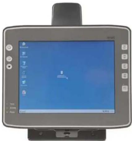
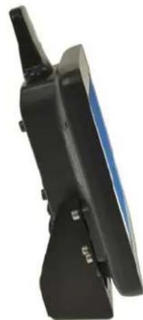
Figure 1 The 8585 Vehicle-Mount Computer
natural_image
Black handheld electronic device with a blue screen and antenna (no visible text or symbols)Scope of Delivery
The delivery includes at least the following:
• 8585 or 8595.
- Cable cover.
• The assembly kit.
- Ignition or Screen Blanking power cable.
- Optionally ordered accessories.
- Quick Start Guide - English and Chinese
Please verify the delivery contents immediately on receipt.
Packaging
The packaging material has been selected to optimally protect your device while simultaneously offering the best possible ecological compatibility. We therefore kindly request that you store the original packaging material or ensure it is used for another suitable purpose such as transporting the unit or returning shipment.
Caution: If you repack the device, please ensure that the cling wrap in the cardboard frame is Property Damage positioned towards the front of the device so that it can provide the proper protection.
Removing the Protective Film from the Display
The front display of the 8585 is protected during transport by a transparent film. This film should remain on the front display during assembly to avoid damage to the front display surface.
Only remove the film once all of the assembly work has been completed.
Returning Your Device
Due care was exercised when putting together the contents of your delivery and dispatching your device. Nevertheless, if you still have cause for complaint, please contact your representative.
Should you need to return the device, please use the original packaging.
About the 8585 / 8595 Vehicle-Mount Computer User Manual
This manual has been designed to make using the 8585 and 8595 Vehicle-Mount Computers as simple as possible and provide expert assistance if problems should occur. The manual generally refers to the 8585 model.
The manual contains important information on using the device safely, properly and efficiently. Adhering to this information helps to avoid dangers, reduces repair costs and breakdown times, and increases the reliability and lifespan of the device.
We will not assume responsibility for any damage caused by the improper use of the 8585 or 8595 and/or disregard of the instructions in this manual.
For Qualified Personnel
This manual was written for qualified personnel. The information is intended exclusively to complement the expertise of qualified personnel, not to replace it.
Keep this Manual
Please keep this manual in a safe place. It should always be at hand near the described device.

WARNING! Before transporting, assembling, and starting the computer, please read this manual carefully and follow all the requirements in Chapter 1: Approvals and Basic Safety Guidelines, as well as the safety guidelines in the individual chapters.
Chapter : About This Guide. provides a basic overview of the 8585/8595 user guide.
Chapter 1: Approvals and Basic Safety Guidelines. describes the safety practices required for the operation of the 8585 and 8595.
Chapter 2: Basic Operation. describes the steps required to get the 8585 ready for operation, device features, connectors, power, and WLAN.
Chapter 3: Installing the Computer. describes the instructions for safely and effectively mounting the computer.
Chapter 4: Operation. describes the touchscreen, keys, operating system, ports, and internal devices.
Chapter 5: Accessories. describes the peripherals and accessories available for your computer.
Chapter 6: Maintenance and Troubleshooting. describes the care of the 8585, steps to investigate problems, and common usage mistakes.
Chapter 7: Device Description and Technical Specifications. lists the specifications for the 8585 and 8595 computers.
Appendix A: Zebra Config Program. describes the detailed configuration information for the Zebra Config program.
Text Conventions

NOTE Notes highlight additional helpful information.

WARNING! This symbol indicates hazards that pose a risk to life and limb (such as contacting the power supply), as detailed below.

IMPORTANT These statements provide particularly important instructions or additional information that is critical to the operation of the equipment.
Caution: This statement warns you of any dangers or hazards that could potentially cause damage to Property Damage the computer or system (such as malfunctions, data loss, equipment damage, etc.).

WARNING! Mild injury is possible.

WARNING! There is a possible risk of death / serious injury.

WARNING! There is an immediate risk of death / serious injury.
CHAPTER 1 APPROVALS AND BASIC SAFETY GUIDELINES
Always Install, Operate, and Maintain the Unit Properly
The 8585 was designed and built according to modern technology and accepted safety regulations. However, the operation of the 8585 can endanger personnel or third parties and cause damage to the device and other material assets, when for example the device is:
- Installed incorrectly or improperly.
- Operated by untrained or uninstructed personnel.
- Improperly operated and maintained.
- Not used as intended.
The operator commitments in regards to safety (accident prevention regulations, work protection) are to be followed.
Safety
In order to prevent injury and damage, please read and observe the following safety guidelines prior to assembly and commissioning. The manufacturer assumes no liability for any and all damages that can be attributed to non-compliance with these guidelines.
Intended Usage
The 8585 is a multifunction terminal for stationary and mobile use in commercial applications (for example logistics, storage, manufacturing). Different or extraordinary usage is not permitted.
For resulting damage, the user/operator of the 8585 is solely responsible.
This also applies to any changes you make to the device.
Compliance with the contents of the safety guidelines is particularly important for the proper use of this device.
Initial Operation of the Device
Area of Application: Not for use in life-support systems or critical safety systems
The device is not designed for use in life-support systems or critical safety systems where system malfunction can lead to the direct or indirect endangerment of human life. The operator shall take full responsibility for using the device in these situations.
The device cannot be used in combination with safety functions for machines and equipment which have to conform to the requirements of EN 954-1.
Installation/Initial Operation
Installation of the 8585 on a vehicle must be performed in accordance with Chapter 3: Installing the Computer. Specifically, special attention must be paid to the various electrical potentials of the vehicle. Some vehicles have a chassis that is connected to one of the battery supply lines (DC+ or DC-), while most electrically-driven forklift vehicles have floating chassis, connected to neither DC+ or DC-. Refer to Vehicle Applications (such as forklifts) on page 3-2 for required wiring of vehicle power and fusing for the 8585.
Risk of injury during transit or installation
The unit could fall during transit or installation and cause injury. Always ensure that there are two persons available when installing or removing the device.
Choice of Location: Observe the Protection Class
The ambient conditions at the point of installation must comply with the device's protection class.
Supply of Fresh Air: Avoid overheating the unit
The 8585 is based on a passive cooling concept. As a result, the waste heat which is produced inside the device is emitted over the surface of the housing. For this system to function properly, sufficient fresh air circulation is required. Never install the system in a closed environment where the cooling air is unable to dissipate accumulated heat to the outside.
If the 8585 is not able to draw in fresh cooling air, this may cause overheating and severe damage to the unit.
The maximum allowed ambient temperature for the system needs to be taken into account for the concrete application area.
Install an easily accessible disconnecting device
The device is not supplied with a disconnector (switch) that can be accessed externally. The power supply connector is therefore used as a disconnector. Therefore it needs to be easily accessible.
If it is necessary to establish a fixed connection, an easily accessible disconnecting device (e.g. a switch such as a circuit breaker) should be installed close to the device. Ensure that the power cable is laid so that it is mechanically protected.
Laying Power Supply Cables: Observe the local installation regulations
The power supply cables must be laid in accordance with the applicable local installation regulations.
Ensure that no persons are injured in case the mounting bracket breaks
The 8585 may in no case be installed in such a way that persons can be injured during a breaking of the mounting bracket (e.g. fatigue break).
If the device is mounted in a place where people can be injured if the bracket should break, appropriate safety measures must be put in place (e.g. install a security cable in addition to the device bracket).
Radio Performance: Do not exceed the maximum permissible transmitting power
Do not exceed the maximum permissible transmitting power which is specified by each separate country. 8585 users must verify this themselves.
Power Supply
The mains power cord shall comply with the national safety regulations of the country where the equipment is to be used.
Operation in an Emergency: Immediately disconnect the device from the power supply
In case of emergency (such as damage to the power cable, or housing, or ingress of liquid or other foreign bodies), the device must be disconnected immediately from the power supply. Contact technical support staff at once.
Protection of the power supplies
If, after replacement, the fuse fed by the internal power supply blows again, the device must be sent in for servicing immediately.
Danger of electrocution when cleaning/servicing the device
In order to avoid electrocution always disconnect the 8585 from the power supply before cleaning or servicing the device.
When charging the vehicle battery please note:
While charging the vehicle battery the 8585 has to be either disconnected from the battery or it has to be determined that the maximum allowed input voltage of the 8585 is not exceeded.
Do not switch on devices with damaged cables or plugs
Do not use the 8585 when a cable or plug is damaged. Have the damaged parts replaced immediately!
Do not connect or disconnect any cables during storms
Cables must never be connected or disconnected during an electrical storm.
External Devices
The use of additional wiring and other peripheral devices, which are not recommended or sold by the manufacturer can result in fire, electrocution or personal injury.
If a power supply is used, only use the power supply recommended by the manufacturer.
Before connecting or disconnecting peripheral devices (exception: USB devices), the 8585 must be disconnected from the power supply! Otherwise, this could seriously damage both the 8585 and the connected devices!
Make sure that external peripheral devices with their own power supply are switched on at the same time or after you start the 8585.
If this is not possible, please ensure that the 8585 is adequately protected from power leakage caused by an external device.
Ensure that the power and grounding of any external peripheral devices to be connected to the 8585 are consistent with the power and grounding of the 8585.
Repairs Only
Never carry out repairs on the device yourself. Always contact technical support and send in your unit for repair if necessary. Refer to the following web site for further details:
www.zebra.com/support
On the back of the 8585 you will find the device's type plate which has important information about the device which you must quote for technical service. It provides important information about the configuration and manufacture of the device in abbreviated form.
Always provide technicians with the full model name and serial number.
CE Marking
Remark for CE class B products: Class B products may be used in residential environment but with the condition that the end user is informed about the possible consequence with a warning information in the user manual:

WARNING! This is a class B device. This equipment may cause interference in a residential installation. In this case the user is encouraged to perform appropriate measures to correct the interference.
RTTE Directive 1999/5/EC
With regard to the RTTE Directive 1999/5/EC the statements in the declaration of conformity for the 8585 apply.
| Malti [Maltese]: | Dan I-apparat huwa konformi mal-?ti?iet essenzjali u I-provedimenti I-o?ra rilevanti tad-Direttiva 1999/5/EC. |
| Magyar [Hungarian]: | Ez a készülék teljesíti az alapvető követelményeket és más 1999/5/EK irányelvben meghatározott vonatkozó rendelkezéseket. |
| Norsk Norwegian]: | Dette utstyret er i samsvar med de grunnleggende krav og andre relevante bestemmelser i EU-direktiv 1999/5/EF. |
| Polski [Polish]: | Urządzenie jest zgodne z ogólnymi wymaganiami oraz szczególnymi warunkami określonymi Dyrektywą UE: 1999/5/EC. |
| Português [Portuguese]: | Este equipamento está em conformidade com os requisitos essenciais e outras provisões relevantes da Directiva 1999/5/EC. |
| Slovensko [Slovenian]: | Ta naprava je skladna z bistvenimi zahtevami in ostalimi relevantnimi pogoji Direktive 1999/5/EC. |
| Slovensky [Slovak]: | Toto zariadenie je v zhode so základnými požiadavkami a inými príslušnými nariadeniami direktív: 1999/5/EC. |
| Suomi [Finnish]: | Tämä laite täyttää direktiivin 1999/5/EY olennaiset vaatimukset ja on siinä asetettujen muiden laitetta koskevien määräysten mukainen. |
| Svenska [Swedish]: | Denna utrustning är i överensstämmelse med de väsentliga kraven och andra relevanta bestämmelser i Direktiv 1999/5/EC. |
Special Rule/Restriction
For the 8585 with WLAN 802.11a/b/g/n, the following restrictions apply:
- WLAN 5 GHz band: 5.15 GHz – 5.35 GHz may only be used indoors.
- WLAN operation outdoors in France is only permitted in the 2454 – 2483.5 MHz range at max. 10 mW EIRP.
Regulatory Summary
FCC User Information
Declaration of the Federal Communications Commission
This equipment has been tested and found to comply with the limits for a Class B digital device, pursuant to Part 15 of the FCC Rules and meets all requirements of the Canadian Interference-Causing Equipment Standard ICES-003 for digital apparatus. These limits are designed to provide reasonable protection against harmful interference in a residential installation. This equipment generates, uses, and can radiate radio frequency energy and, if not installed and used in accordance with the instructions, may cause harmful interference to radio communications. However, there is no guarantee that interference will not occur in a particular installation. If this equipment does cause harmful interference to radio or television reception, which can be determined by turning the equipment off and on, the user is encouraged to try to correct the interference by one or more of the following measures:
- Reorient or relocate the receiving antenna.
- Increase the separation between the equipment and receiver.
- Connect the equipment into an outlet on a circuit different from that to which the receiver is connected.
- Consult the dealer or an experienced radio/T.V. technician for help.
Zebra is not responsible for any radio television interference caused by unauthorized modifications of this equipment or the substitution or attachment of connecting cables and equipment other than those specified by Zebra. The correction of interference caused by such unauthorized modification, substitution or attachment will be the responsibility of the user. The use of shielded I/O cables is required when connecting this equipment to any and all optional peripheral or host devices. Failure to do so may violate FCC and ICES rules.

WARNING!
FCC warning: Any change or modification which is not expressly approved in the corresponding pages can lead to the withdrawal of the operating license for this device.
In order to comply with the FCC requirements regarding radio frequency exposure from vehicle-mounted transmission devices the antenna has to be kept at least 20 cm away from people.
Transmission of Radio Frequencies
Use care in airplanes or in clinical/medical areas
Some devices in hospitals and airplanes are not protected from radio frequency energy. Consequently, do not use the 8585 in airplanes or hospitals without prior authorization. Here use of the 8585 is only permitted if authorization is obtained.
Caution with pacemakers
Do not use the 8585 near pacemakers. The 8585 can affect the function of medically implanted devices such as pacemakers and create interference. Do not place the 8585 near such devices.
Keep a minimum distance of 20 cm between such a device and the 8585 in order to reduce the risk of interference.
If you have reason to assume that interference has occurred, then turn the 8585 off and consult a heart expert.
Country Roaming
This device incorporates the International Roaming feature (IEEE802.11d) which will ensure the product operates on the correct channels for the particular country of use.
Declaration of Conformity
Declaration of Conformity (DoC) is available at: http://www.zebra.com/doc
Regulatory Information for China
Class A Product Warning
Chinese Warning Statement for Class A ITE
Warning
This device is Class A. The device may generate radio interference at home. The user may need to take realistic action at the interference.
警告
Local language translations are available at the following website:
http://www.zebra.com/CN-ZH/Pages/Contact_Us#support_tab
Quality Certificate in Chinese when the Factory has ISO 9001 Certification
合格证 Quality Certificate
合格证
Removing the Protective Film from the Display

WARNING! Before operating the unit for the first time, carefully read Chapter 1: Approvals and Basic Safety Guidelines.

NOTE Configure the computer before fastening it to machines or vehicles. Software configuration for the WLAN, shutdown automation, etc. is significantly simpler and more convenient on the desktop.
The front display of the 8585 is protected during transport by a transparent film. This film should remain on the front display during assembly to avoid damage to the front display surface.
Only remove the film once all of the assembly work has been completed.
Zebra Config: Front Keys, WLAN, Automatic Switch-off
The Zebra Config program can be found on your 8585. Use it for settings such as the following:
- Configuring the front keys of the 8585.
- Setting up the WLAN status display.
• Turning the 8585 on and off together with the vehicle ignition (automatic switch-off).
NOTE To configure units with AMD installed, Config Tool Version3.1.1.0 or higher is required.

Figure 2-1 Zebra Config Program Menu
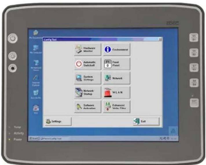

NOTE You can find detailed configuration information in Appendix A: Zebra Config Program.
WLAN Settings
The settings and access data form must be defined for radio networks like WLAN depending on the optional equipment and intended use of the 8585.

WARNING! Please pay attention to all basic safety guidelines for WLAN, especially RTTE Directive 1999/5/EC on page 1-4 and FCC User Information on page 1-5.
Radio Performance

WARNING! Do not exceed the maximum permissible transmitting power which is specified by each separate country. 8585 users must verify this themselves.
Please keep in mind the configuration for the transmitting power:
- Wireless card (programmed driver capacity).
- Connecting cables.
- Antenna gain.
Help table for the correct setting:
| Translation between mW and dBm | ||||||||||||||||||||||
| dBm | -1 | 2 | 5 | 6 | 7 | 8 | 9 | 10 | 11 | 12 | 13 | 14 | 15 | 16 | 17 | 18 | 19 | 20 | 21 | 22 | 23 | 24 |
| mW | 1 | 2 | 3 | 4 | 5 | 6 | 8 | 10 | 12 | 15 | 20 | 25 | 30 | 40 | 50 | 60 | 80 | 100 | 125 | 160 | 200 | 250 |
Antenna Solutions for Use in Germany
The integrated antenna solutions are based on the prevailing IEEE 802.11 standard. This standard allows wireless data transfer at rates from 1 Mbps to 54 Mbps using the 2.4 GHz and 5 GHz frequency band (300 Mbps if using IEEE 802.11n).

WARNING! In Germany according to regulations published in the gazette 89/2003 of the RegTP (regulating body for telecommunications and mail), now: "Bundesnetzagentur" - Federal network agency for electricity, gas, telecommunications, post and railway - the maximum permissible transmitting power, EIRP (equivalent isotropically radiated power), in the 2.4 GHz frequency band is set at 20 dBm.
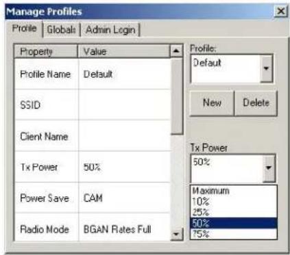
The transmitting power of the integrated Zebra antenna (Zebra 3 dBi) must be set to 50 mW (17 dBm) so that the EIRP limit value is adhered to when using the antenna.
Example configuration of the transmission power using the Laird Connection Manager program:
Figure 2-2 Configuring the antenna transmitting power with Laird (example)
Laird Connection Manager for WLAN Configuration
The Laird Connection Manager is used to set up the WLAN configuration for the 8585.

WARNING! WLAN configurations may only be modified by qualified IT technical staff.
Launch this connection manager with a double tap on the Laird Connection Manager icon on the desktop:
Figure 2-3 Laird Connection Manager Icon
Admin Password
In order to make adjustments in Laird, it is necessary to enter a password.
- To do so, click the Admin Login tab. An input field appears for the password.
Figure 2-4 Laird Connection Manager Admin Password input
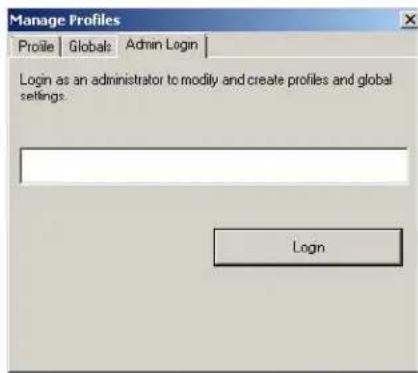
The standard password is: SUMMIT (must be entered in capital letters!) You can find details about the configuration parameters in the Laird Connection Manager user guide at:
http://www.lairdtech.com/brandworld/library/User%20Guide%20-%20Laird%20Connection%20Manager.pdf
Protecting the TFT Display from the Memory Effect
The TFT display of the 8585 has to be protected from the burning in of a motionless image. An image that has remained motionless for too long can cause irreversible damage to the display. With TFT displays there no cathode rays burning in an after-image as in old TV sets or monitors, but TFT displays still have a memory effect. This is because with a still image the liquid crystal molecules align themselves in a certain way and become inert if they are not moved. Like burning in the effect is irreversible, but can be avoided by regularly turning off the display or by using a screen saver with changing content.
Define in the power management centre of the utilized operating system that the displays of the 8585 should be turned off when no user input occurs.
A motionless image can stay on the display for a maximum of 12 hours. After more than 12 hours there is the risk of the memory effect.
Connectors
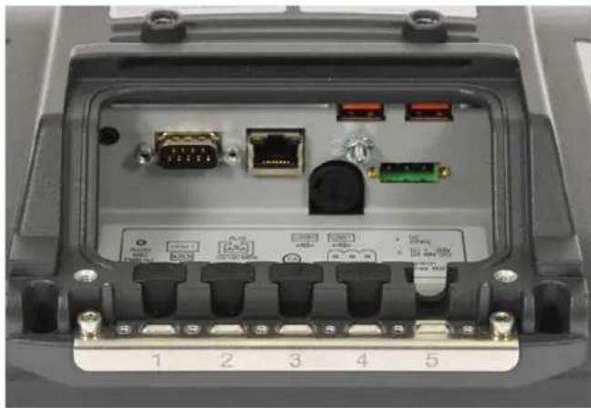
Overview of External Connectors
Figure 2-5 Connectors overview
natural_image
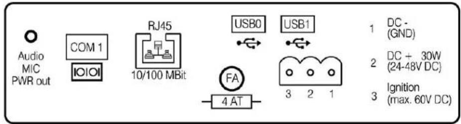
Back view of an electronic device showing ports, connectors, and a central switch (no readable text or symbols)Figure 2-6 External connectors detailed view (example 24/48 VDC)
Adaptor Cables
Two types of adaptor cables are available for use with the 8585/8595. An extension power cable (PN 13985–301) is available as an accessory. The power extension cable is connected to the vehicle on one side and the adaptor cable on the other side. All cables can be used with every voltage. Zebra offers an ignition and a screen blanking (display-off) adaptor cable. The external wire of the adapter cable must be connected to the ground lug of the terminal and to the vehicle chassis.

NOTE Refer to Wiring Vehicle Power to the 8585/8595 on page 3-3 for details about ignition and screen blanking installation instructions.
If you require Pre-Regulator or UPS installation instructions, please contact Zebra personnel for assistance.
The ignition adaptor cable is connected to the power input of the 8585/8595 only; the screen blanking cable must be connected to the power input and COM1. If you require both the screen blanking and the ignition options, you will need to contact Zebra personnel for assistance.
Figure 2-7 Adaptor Cable Options
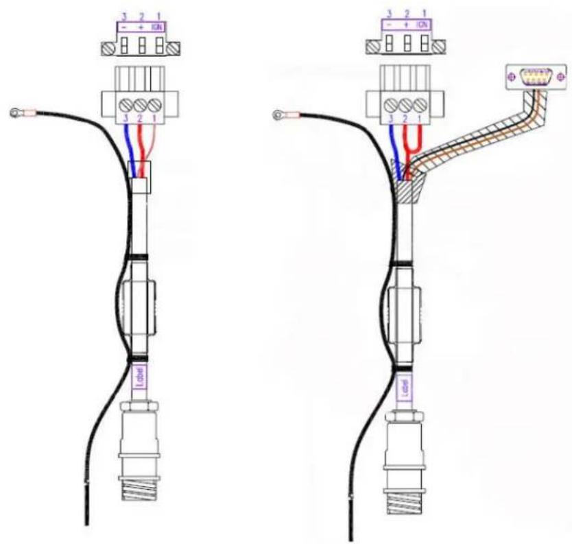
Ignition Adaptor Cable Screen Blanking Adaptor Cable PN 1616302-001 PN 1616303-001
DC Voltage Supply Connector
Version: Phoenix Combicon, 3-pin.
Figure 2-8 External view of the DC power supply connector
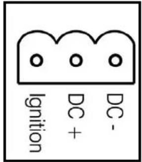
Explanation:
Ignition on means that a control signal has to be routed to this connection (e.g., ignition of a vehicle), that matches the supply voltage level and is able to supply at least 1 W to the 8585.
The signal reference is DC-.
Connecting External Devices
The 8585 must be disconnected from the power supply:
- Before external devices (e.g., scanner, keyboard) are connected or disconnected, and
- Before the 8585 can be connected to a network.
All connections and interfaces on the 8585 are located on the underside of the unit.
Ensure that the power and grounding of any external peripheral devices to be connected to the 8585 are consistent with the power and grounding of the 8585.
Caution: Make sure that external peripheral devices with their own power supply are switched on at the same time as the 8585 or after you start the 8585. If this is not possible, please ensure that the 8585 is adequately protected from power leakage caused by an external device.
Only power up the 8585 when all devices have been connected and the 8585 has been closed correctly (remember the cable cover!). Otherwise, you may damage the 8585.
Powering Up the 8585
Only power up the 8585 after connecting all of the devices.
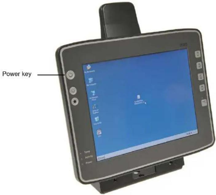
The 8585 is powered up by connecting it to an appropriate power supply and then, depending on the version of the device, either using the [Power] key or the ignition signal.
You have to hold the [Power] key down for a short time.
Caution: Make sure there is a suitable disconnecting device such as a power switch or circuit breaker in the Property power supply circuit. Damage
Figure 2-9 8585 Power key
Powering Down the 8585
Always shut down the 8585 as follows:
- Power down the device using the ignition input or the [Power] key.
- Remove the cable cover.
- Disconnect the device from the DC supply voltage (pull the plug).
CHAPTER 3 INSTALLING THE COMPUTER
Overview
The 8585 can be installed in a variety of ways:
- It can be positioned horizontally on a desk or mounted on a steering wheel and vehicle console.
- Wall mounts are also available for mounting the unit on machines and operating panels.
• Roof mounting is also possible, for example under the vehicle roof.
Depending on the vibration resistance and pivoting demands, mounting brackets, clamp foots or RAM mount elements can also be used to attach the device. Please contact your Zebra sales office to find out more about the whole range of installation options on offer.

WARNING! The unit could fall during transit or installation/mounting and cause injury. Always ensure that there are two people available when installing or removing the device.
Follow and Retain the Mounting Instructions
Please follow the mounting instructions included with assembly kit when installing your 8585. Please make sure that you retain the instructions.
Pay careful attention to Chapter 1: Approvals and Basic Safety Guidelines.
Mechanical Dynamic Loading
Since the 8585 is a weighted structure, it is invariable that the unit will be subject to mechanical dynamic effects. Therefore optimizing the mounting is necessary.
Cooling Through the Supply of Fresh Air
The 8585 employs a passive cooling concept whereby the waste heat generated inside the device is emitted from the surface of the housing. For this system to function properly, sufficient fresh air circulation is required.
Never install the system in a closed environment where the cooling air is unable to dissipate accumulated heat to the outside.
Caution: If the 8585 does not have access to fresh cooling air, it may result in overheating and property severe damage to the unit. The maximum permissible ambient temperature for the entire Damage system needs to be taken into account for the concrete application area.
Power Supply
The 8585 is equipped with a galvanically separated, integrated DC power supply.
Power is connected to the underside of the unit using a Phoenix Contact plug. There is no power switch.
Caution: The 8585 must only be connected to a SELV circuit. *Ensure that there is a suitable disconnecting device such as a power switch or circuit breaker in the power supply circuit. Ensure that the disconnecting device isolates all supply voltage lines. The DC+ connecting cable must be protected by a fuse (30 AT max.). The ignition connecting cable must be protected by a fuse of the following type: 5x20 mm T 125 mA L / 250 V, for example, a Wickmann 195-125 mA / 250 V.
* The SELV circuit is a secondary circuit that is designed and protected so that its voltages will not exceed a safe value both when operating correctly or if a single error occurs.

WARNING! Use the connecting cables supplied by Zebra to connect the 8585 to the power supply.
Make sure that the connecting cables are laid without kinks and are protected.
Vehicle Applications (such as forklifts)
Electrical Installation
Pay special attention to the various electrical potentials when installing the unit on a vehicle (such as a forklift).
In the 8585, the logic ground and the shield ground are firmly linked.
The “logic ground” is the earth line (GND) for all of the internal electrical components, such as the display and the CPU.
The cable shielding and the housing are connected to the "shield ground".
Caution:
Property
Damage
WARNING! PAY CLOSE ATTENTION TO THE FOLLOWING WARNINGS!
Some forklifts have a chassis that is connected to DC+. Therefore, the 8585 chassis is also connected to DC+. However, if you use peripheral devices that supply DC- to the 8585 via an interconnector (such as a DC- serial port), this will cause a short circuit. This will inevitably lead to malfunctions or even a total system failure.
Always attach the ring tongue on the white supply voltage cable to the ground bolt situated on the connector bay.
Most electrically-driven forklift vehicles have floating chassis, connected to neither DC+ or DC-. However, electrical faults can cause the battery + or - to be connected to the chassis via low resistance paths. All connected peripherals must be completely isolated.
Figure 3-1 Position of the ground bolt
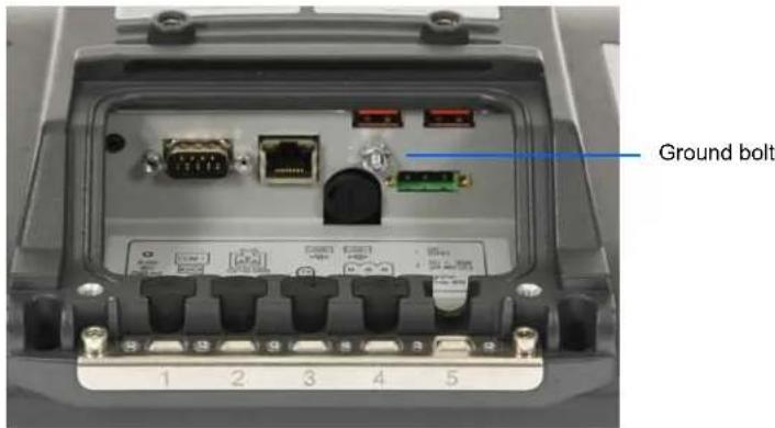

WARNING! Individual vehicle requirements and any installed supplementary electronic systems on the vehicles must be reviewed to ensure 8585/8595 grounding is compatible - follow vehicle manufacturers recommendations.
• The other end of the white supply voltage cable should be connected to the vehicle's chassis.
• Make sure that the 8585's connecting cable is attached as close to the battery as possible. Connecting the 8585 to large electrical loads, such as converters for the forklift motor may result in random restarts, malfunctions and/or irreparable damage to the device.
- If you want to connect devices fed by other power sources to the 8585, such as printers and so on, be sure to power up the peripheral devices at the same time or after the 8585. Otherwise, you may encounter start-up problems, malfunctions or even irreparable damage to the device.
Wiring Vehicle Power to the 8585/8595

WARNING! Applying a voltage above the input voltage rating or reversing polarity may result in permanent damage to the 8585/8595 and will void the product warranty.
A 1.8 meter (6 ft.) extension power cable (PN 13985–301) is available which should be used to wire the 8585/8595 to the truck battery. This cable needs to be ordered separately. This cable should be wired to a filtered, fused (maximum 10A) accessory supply on the vehicle. On negative chassis vehicles, the positive lead
should be fused. On positive chassis vehicles, the negative lead should be fused. On floating chassis vehicles, the positive and negative leads must be fused. Any additional wiring (minimum 18 gauge), connectors or disconnects used should be rated for at least 90 VDC, 10 A.
When connecting PN 13985-301, ensure that the screen blanking wires (clearly labelled) and the power wires (red/black leads) are reliably secured away from each other, or are separated with reliably secured certified insulation. Minimum 2.8 mm distance, or 0.4mm distance through insulation is required for the separation.
The red lead of the power cable attaches to the positive vehicle supply. The black lead connects to the negative supply – this should be connected to a proper terminal block and not to the vehicle body. The external wire of the power adapter cable is connected to the ground lug of the 8585/8595 terminal connector bay and to the vehicle chassis.
You have the option of connecting power before or after the key switch. The 8585/8595 should not be shut off by simply removing the power. If it is wired after the key switch, the operator must shut down the 8585/8595 using the Windows shutdown procedure before turning off the vehicle. If it is wired before the key switch, then to avoid excessive drain on the vehicle battery, either the operator should shut it down when the vehicle is to be left off for an extended period, or the ignition cable shutdown wire should be connected and the 8585/8595 configured to shutdown automatically.
If an unfused power source must be used, a fuse assembly (PN 19440-300) and diode/choke assembly (PN 30723-301A) must be added to the extension power cable (the fuse, diode/choke and instructions are supplied with the cable). Use only a 10A slow blow UL approved fuse in the fuse assembly. The fuse assembly must be located as close as practical to the DC supply, and shall connect to either the positive, or negative side of the DC supply, depending on the chassis grounding scheme. For floating chassis vehicles, an additional 10 A slow blow UL approved fuse (fuse assembly PN 19440-300) should be installed on both power supply lines.
To safely wire power to the 8585/8595, review these guidelines and follow the instructions that apply to your needs:
- When connecting the cable (PN 13985-301) to the screen blanking cable (PN 1616303-001), the wire pair on the 13985-301 labelled "screen blanking" connect to the screen blanking control device, which must provide an isolated relay closure across the pair.
- When connecting the cable (PN 13985-301) to the ignition cable (PN 1616302-001), the wire pair labelled "screen blanking" on the 13985-301 has a different function; the red wire must connect to a DC+ voltage source switched on by the ignition, while the black wire may connect to DC- or be taped off.
- Note that only the ignition function is supported by the UPS (models PS1110/PS1120), not the screen blanking. If both screen blanking and ignition are to be used on the same 8585/8595, contact Zebra for details.
Position of the 8585 in the Vehicle
In the vehicle, the driver's field of view must be kept free.
If a keyboard and scanner are installed on the 8585, please plan sufficient space.
No part of the 8585 system may project beyond the vehicle.
Overview of the Assembly Steps
Before fastening the 8585 to the vehicle:
- The shutdown automation must be configured.
• The forklift must be prepared (connection to ignition, correct voltage, etc.).
We recommend the following installation sequence:
-
Fasten the bracket to the vehicle.
-
Install 8585 to the bracket.
Cable Cover (splash guard)
Caution: For safety reasons, the supplied cable cover for the external ports must be installed prior to using
Property the 8585.
Damage
Protection class
In order to comply with the certified protection class, please use the assembly kit included with the 8585.
Please observe the installation instructions included with this assembly kit.
Strain Relief
After the 8585 and bracket are fastened:
• Prepare the strain relief.
- Install the cables loosely on the strain relief rail.
• As far as possible, route cables leading to or away from the unit next to one another without crossing.
Completing:
- Fasten the cables to the strain relief rail.
- Be sure that the cables are fastened precisely at the positions at which the cable openings in the cable cover are located.
Minimum Distance to WLAN Antenna

WARNING! In order to avoid exceeding the limits determined by the FCC for exposure to radio waves, you (and other people in your vicinity) should maintain a minimum distance of 20 cm from the antenna integrated into the computer.
Please note this when mounting Zebra industry computers with WLAN antennas.
Antenna Cap and Service USB Interface
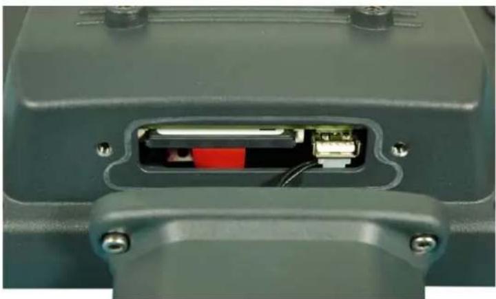
Under the antenna cap (protective cap) of the 8585, there is a Service USB interface.
Figure 3-2 Antenna cap 8585
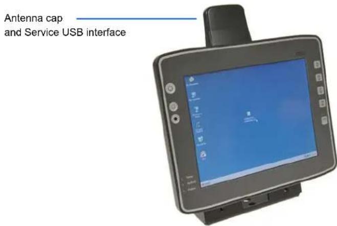
To access this Service USB interface, you need to remove the antenna cap from the unit.
Caution: Incorrect or improper removal and fastening of the antenna cap can impair the function of the entire Property 8585 system. These actions, or if the 8585 is operated with the antenna cap/service USB interface open Damage for a longer period of time than required for service tasks, will invalidate any warranty provided by Zebra. The service USB interface may only be used for maintenance purposes, e.g. to load software updates. The antenna cap/service USB interface may only remain open for the duration of the service work. It may only be opened and closed by qualified technical personnel.
No objects or fluids may be introduced into the 8585 while the antenna cap and the USB interface are open.
Only when the antenna cap/service USB interface is properly closed again may operation be resumed; protection class is then ensured again.
Figure 3-3 Service USB under the antenna cap
Do not pull the antenna connection cable too far out of the unit, catch it, or cut it.
natural_image
Close-up of a mechanical component with internal wiring and a red connector (no visible text or symbols)Unfasten antenna cap from unit and refasten it:
- Unscrew the two screws from the antenna cap with an Allen key (size 3 mm).
-
Lift the antenna cap carefully to avoid pulling on the antenna connection cables (max. 2 to 3 cm).
-
Holding the antenna cap, making sure that no pulling tension is exerted on the antenna connection cables.
- The Service USB interface is now accessible.

WARNING! One end of the antenna connection cables is attached to the antenna cap, the other end to the internal WLAN unit of the 8585. The cables must not be pulled out of the 8585 too far and become detached from the WLAN unit! This might damage the WLAN unit or other components of the device.
- Place the antenna cap back onto the 8585.

WARNING! Take care not to trap the antenna connection cables when doing this. The antenna cap seal must not be damaged; it must be seated correctly in the groove.
- Reinsert and tighten the two screws of the antenna cap (1 Nm torque).
CHAPTER 4 OPERATION
Touchscreen
The 8585 is equipped with a resistive touchscreen.
Caution: Keep the panel surface clean.
Property Damage Prevent any kind of adhesive from being applied to the surface.
Avoid high voltage and/or static charge.
Touchscreens may not be operated with ball-point pens or writing utensils, tools of any kind (e.g. screw-drivers) or with sharp objects (knives, scalpels, etc).
Touch the panel with your finger or stylus only to ensure normal operation. Any sharp-edged or hard objects are prohibited.
Operate the panel in a stable environment. Abrupt variation on temperature and humidity may cause malfunction of the panel.
Avoid applying excessive activation force or sudden impact on the panel surface.
Construction Type and Resistance
- 5-wire touch sensor using analog-resistive touch technology.
- Construction: Film-Glass (FG).
- Hardness of surface: 3H (ASTM D3363).
- Resistance: 35 million actuations.
Operation
Operation of the resistive touchscreen is recommended with:
- Clean, dry fingers.
- Clean, dry, soft gloves.
- Suitable touch stylus (plastic or wood, rounded tip).
Cleaning
Use neutral detergent or isopropyl alcohol on a clean soft cloth to clean the panel surface.
Prevent using any kind of chemical solvent, acidic or alkali solution.
Touch for MS Windows Embedded Standard 7
Installation
The touch drivers to be used can be found on the Flash medium under Util/atouch/
- Open the corresponding folder and run Setup.exe.
- On the Welcome dialog click Next.
- In the Software License Agreement window select: I accept all of the terms of the above License Agreement and then click Next.
- On the Select Controller dialog choose serial (RS/232) and click Next.
- On the Serial Configuration dialog choose COM2 and 9600 Baud and click Next.
- Deselect the option on the Configuration Complete dialog and close by clicking Finish.
- Two Files Needed windows will appear querying the path to the tsufiltr.sys file (see Figure 4-1 Files Needed touch installation dialog).
- Select Browse to navigate to the installation folder indicated above, then choose the Serial folder and click OK.
Figure 4-1 Files Needed touch installation dialog

- Confirm the final message Setup is now complete by clicking OK.
The computer does not need to be restarted.
Calibration
The touchscreen must be calibrated so that it functions correctly.
- Start the touch configuration tool under Start/Programs/Hampshire TSHARC Control Panel.
- Select the Calibration tab and click the Touch field.
- Once calibration is complete, finish by clicking Accept.
- Select the Click Settings tab and select Enable right click emulation and enter the following values:
Right-Click Area + Double-Click Area each to 13;
Right-Click Delay + Double-Click Delay each to the third line.
- Exit the tool with OK.
Front Keys and LEDs
The 8585 has the following front keys and LEDs:
Figure 4-2 8585 front keys and LEDs
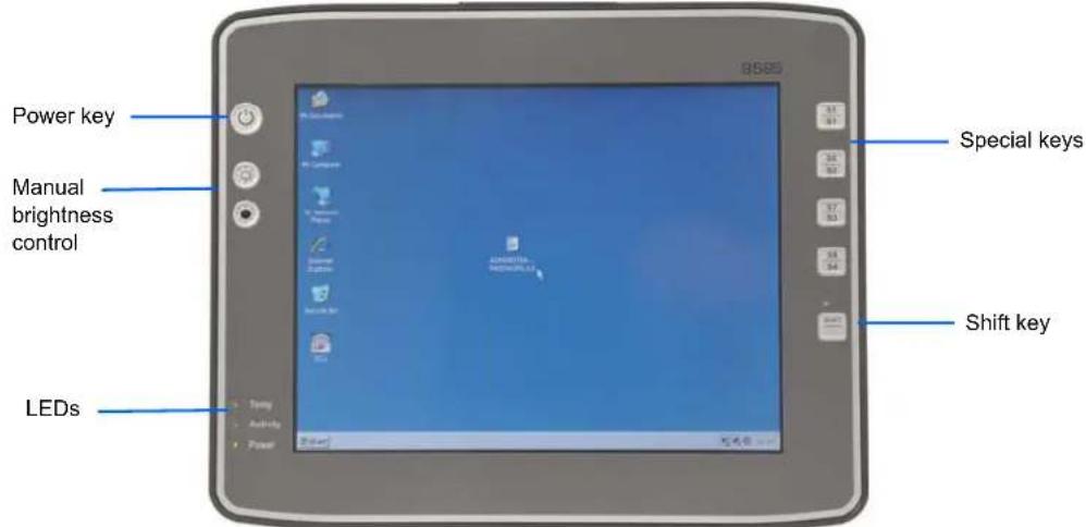
Power Key
If you want to start the 8585 using the [Power] key:
- You must hold the [Power] key down for a short time.
Manual Brightness Control
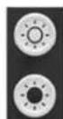
Manual brightness control: brighter
Manual brightness control: darker
LEDs
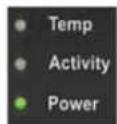
Temp (red) LED indicates an excessively high or low temperature inside the unit.
Activity (green) LED indicates access of the flash drive.
Power (green) LED indicates an available internal power supply.
Special Keys
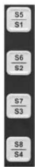
Special keys [S1] to [S8]
The special keys can be configured with the Zebra Config program (select the Front keys menu).
Shift Key

Switch the keys [S1], [S2], [S3] and [S4] to [S5], [S6], [S7] and [S8].
The lucent LED indicates an activated [Shift] key.
Operating States
The following are the 8585 operating states.
| Status of Internal LEDs | 8585 Status | |
| Temp (red) | ||
| OFF | OFF | Initial state, idle time - waiting for a new ignition signal after switch-off; no power supply |
| OFF FLASHING | Temperature sensor | malfunctioning |
| FLASHING OFF | 8585 is in stand by mode (S3) | |
| OFF ON The computer will not start until the temperature inside the unit returns to between -30 °C and +62 °C | ||
| ON OFF Computer is starting up; normal operational state; shutdown delay time is running | ||
| Power (green) Temp (red) Temp. < -30 °C or Temp. > 70 °C | ||
| OFF OFF Temperature sensor malfunctioning; automatic switch-off software configuration | ||
Operating System

Images for the 8585 devices cannot be run on Intel devices. If the wrong image is used, a blue screen appear with the following technical information: 0X0000007B)
Pre-installed on Flash
When an 8585 with a pre-installed operating system is started, the operating system is loaded following the BIOS boot messages.
System-specific device drivers — such as those for graphic, sound, network and touchscreens — are also pre-installed.
In 8585 units with a pre-installed operating system, the system is located on the C partition.
Installing on Flash
When an 8585 is started up for the first time without a pre-installed operating system, the user needs to carry out a number of steps that will vary depending on the system to be installed. Refer to the relevant operating system manual for specific instructions.
Caution: The installation and configuration of the operating system should only be carried out by professionals Property familiar with the system environment.
Damage
Special Features of the Operating Systems
If the 8585 is running MS Windows XP Embedded or Windows Embedded Standard 7, not all USB devices will be supported.
Serial Port
The 8585 is equipped with an externally accessible serial interface COM1.
Resources for the serial port are pre-defined in the system architecture and automatically managed by the BIOS.
COM1 as a Power Supply
The COM1 port can optionally supply externally connected equipment with +5 V of power.
The voltages are protected by internal fuses which limit the total consumed current to 1.1 A at 5 V.
Depending on the specific system configuration, the maximum current consumption may be significantly lower.
Serial Port Printers
Printers with a serial port can be connected to the 8585.
Serial Port Bar Code Scanners
To activate the integrated scanner software wedge under MS Windows 7
- Open the Start menu and navigate to Settings>Control Panel>Accessibility.
- Select the General tab.
- Select Support accessibility options.
- Click Settings.
- Configure the desired COM1 port and BAUD rate.
-
Confirm the change with OK.
-
Click OK again for the changes to take effect.
Caution: Please note that you have to configure the scanner correctly to RS-232 and the above set BAUD rate Property following the scanner manufacturer's guidelines. Otherwise the software wedge will not function Damage properly.
Tips and Tricks
Note that according to the EIA-232-E specification, the maximum cable length is 15 m at 19,200 bps.
By using a correctly terminated twisted-pair cable, however, up to 1,200 m at 100 kbps can be achieved according to the EIA-422-A specification. With a data rate of 1 Mbps and a high-quality cable, it is possible to reach cable lengths of up to approximately 400 m.
Malfunctions in the RS-232 connections are frequently caused by ground loops. If both end devices establish a ground connection via RS-232 but do not share the same ground potential in their power supply circuits, then compensation currents may result. This is particularly noticeable with long cables.
These compensation currents, which are also present at the ground point of the RS-232 connection, may significantly degrade signal quality and effectively stop the data flow. In challenging environments, electrically-isolated connections (via external converters) or differential systems (RS-422/485 port) are strongly recommended.
Internal Devices
Chipset
The 8585 computer is equipped with a chipset which controls the communication between all function modules.
The chipset converts the signals it receives from the CPU into memory access, flash access and other similar actions. Likewise, it transmits requests from peripheral devices to the CPU. Input devices such as the mouse or keyboard also communicate with the system via this chipset.
VGA Adaptor
The 8585 is equipped with a VGA-compatible adaptor. This adaptor controls the integrated display.
Onboard Sound Controller
The 8585 is equipped with an onboard sound controller.
This controls the audio output via the internal speaker, or the optional Speaker/Mic with push-to-talk function (Model Number M1000).
Network Adaptor (10/100/1000)
The 8585 is equipped with a 10/100 Mbit network adaptor. This adaptor features an RJ45 port.
The network controller undertakes the entire task of connecting the hardware to the network.
The RJ45 connection port features two integrated status LEDs. They display the following messages:
Figure 4-3 RJ45 network port
Left LED (Green)
LED off: operating as 10-Mbps connection
LED on: operating as a 100-Mbps connection
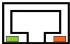
Right LED (Amber)
LED off: no link is established
LED blinking: there is activity on this port
Problems with Data Transmission via LAN/Ethernet
If problems occur during data transmission over LAN/Ethernet (e.g. data is lost or not detected), the cause of these problems may be a cable which is too long.
Depending on the cable layout and interference from the environment, it may be impossible to use the cable length of 100 m given in the specification (IEEE 802.3 standard).
The solution here is the use of a shorter cable.
Automatic Switch-off
The 8585 is equipped with an automatic switch-off module.
Modes of Operation
If wired up accordingly, the 8585 conveniently switches off together with the vehicle's ignition.
As disconnecting the power supply during operation can lead to data loss, the operating system needs to be shut down normally using the appropriate hardware and software installed on the system when the ignition is switched off.
The 8585 is connected to the vehicle with three supply cables. DC+ and DC− are directly connected to the power supply of the vehicle, the connection is run through fuses. Therefore make sure that the cables are connected directly to the battery and not to high-interference supply lines (for example, motor supply) or to supply lines already used by other consumers.
The supply voltage connected is then linked to the 8585's ignition input via a switch, for example, the key switch of the ignition (also with a fuse).
Automatic Switch-off Process
When the ignition is switched on, the 8585 is supplied with power and begins checking its internal temperature and automatic switch-off function.
Once the ambient conditions have been verified as acceptable, the 8585 starts the operating system just like normal.
During the first three minutes of the start-up phase, none of the ambient conditions, such as the internal temperature or the Ignition input status, are checked. This allows the operating system and the operating software for the automatic switch-off module to fully load without interruption.
Following this three-minute period, the internal temperature of the unit and the status of the Ignition input are checked continuously.
If the inner temperature of the 8585 reaches a critical range, the operating system is shut down normally and the computer remains switched off until the temperature is back in the permitted range.
If the Ignition input is switched to earth potential or a potential-free source during normal operation, the unit switches to shutdown delay time.
In this state, the device continues to operate normally until the delay time (for example, 15 minutes) has elapsed.
• If the ignition is triggered again during this time, the 8585 resumes normal operation.
- If, however, the delay time elapses, the operating system is shut down normally by the operating software and the unit is automatically switched off (for example, after three minutes, or after a signal from the operating software).
Configuration with Zebra Config Program
The Zebra Config program must be installed for the automatic switch-off module to function correctly.
If the Zebra Config has not been started, the 8585 will carry out a hard shutdown once the delay time and shutdown time set by the hardware (e.g. via MPCCOM.EXE) has elapsed. In this case, the operating system is not shut down normally before the power is switched off. The current application is unable to save its data, and the file system becomes increasingly unstable and inconsistent.
If the Zebra Config has been started, the program can recognize when the operating system needs to be shut down. Firstly, the Windows message WM_QUERYENDSESSION is sent to all running applications to inform them of the impending shutdown.
Now every application has to respond within the time that is set in the registry (see the Automatic Switch-off Configuration Dialog on page A-6). If a response is not sent in the specified time, the application is forced to quit.
If there are any open programs with unsaved changes, it may not be possible to automatically quit them (for example, an unsaved document in WORDPAD.EXE, a program supplied with Windows). In this case WORDPAD.EXE responds to the Windows message WM_QUERYENDSESSION with a user query to confirm if the current file is to be saved. Applications that can be quit with the key combination [ALT] and [F4] (that is, without a final user query) generally send the required response to the WM_QUERYENDSESSION message and are not shutdown "hard".
To ensure that vital data is always saved correctly, applications need to be able to properly respond to the WM_QUERYENDSESSION message, that is, without user queries and within the set time period.
Further information on the Zebra Config program can be found in Appendix A: Zebra Config Program.
CHAPTER 5 ACCESSORIES
Keyboard
Any USB keyboard can be connected to the 8585.
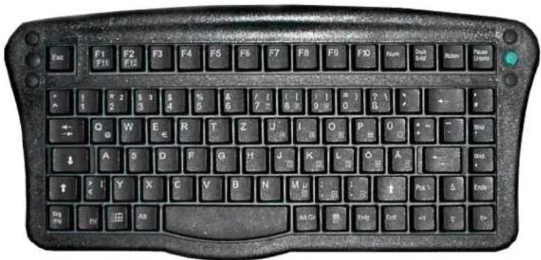
SMALL Keyboard
A mountable SMALL keyboard with protection class IP 65 is available for the 8585.
Figure 5-1 SMALL keyboard
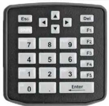
24-key Keypad
A 24-key keypad which can be mounted onto the 8585 is available, with a protection class IP 65.
Figure 5-2 24-key keypad
Scanner Bracket
Scanner brackets are available for the 8585 for current scanners (optional). Scanner brackets can be fastened to the left or right of the unit.
Mouse
Any USB mouse or any mouse with a RS-232 port can be connected to the 8585.
USB Stick
You can connect a USB stick to the 8585 with a USB-A connector.
USB Recovery Stick
With the optional Zebra recovery stick, images can be backed up and restored on the 8585 if necessary (backup and recovery). Please consult your Zebra sales representative if necessary.
Scanners
You can connect scanners to either the USB port or the serial port. If connected to COM1, the scanner can be powered through the port (optional, 5 V).
NOTE The DS3508ER can not be powered through the USB; it needs to be connected to the serial port.

Be sure to only use scanners that have been approved by Zebra.
WLAN Card (PCIe MiniCard)
The WLAN card is integrated into the unit by Zebra at the factory (internal PCIe MiniCard slot).
In general, only drivers for WLAN cards approved by Zebra can be integrated into operating system images.
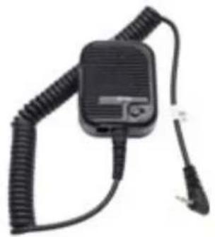
Microphone (Voice Kit)
M1000 Speaker/Mic
natural_image
Black handheld electronic device with coiled cable and connector (no visible text or symbols)CHAPTER 6 MAINTENANCE AND TROUBLESHOOTING
Maintenance

WARNING! Danger due to electric shock when cleaning and maintaining the device.
To avoid electric shock, turn the 8585 off and disconnect it from the power supply before cleaning or maintaining it.
Cleaning the Housing
The housing of the 8585 is best cleaned with a damp cloth.
Do not use compressed air, a high-pressure cleaner or vacuum cleaner, as this can damage the surface.
Using a high-pressure cleaner poses the additional risk of water entering the device and damaging the electronics or display.
Touchscreen Cleaning
Use neutral detergent or isopropyl alcohol on a clean soft cloth to clean the panel surface.
Prevent using any kind of chemical solvent, acidic or alkali solution.
Troubleshooting
Data Transmission via LAN/Ethernet
If problems occur during data transmission over LAN/Ethernet (e.g. data is lost or not detected), the cause of these problems may be a cable which is too long.
Depending on the cable layout and interference from the environment, it may be impossible to use the cable length of 100 m given in the specification (IEEE 802.3 standard).
The solution here is the use of a shorter cable.
Images for AMD Devices are not Compatible with Intel Devices
Images that were created for 8585 devices with an Intel processor cannot be used on AMD devices – they are not compatible.
Using the wrong image results in a blue screen with the following technical information: 0X0000007B.
8585/8595 AMD: Switch Off/Restart
If ambient temperatures exceed 40^a C, the processor comes under high strain or output is extracted externally via peripheral interfaces (USB, serial) the 8585/8595 may switch off or restart under unfavourable conditions.
Corrective action: Ensure sufficient cooling. Supply the connected external peripheral devices from other external sources.
Common Mistakes in Usage
Intel Images are not Compatible with AMD Devices
- Do not copy images that were created for Intel processors to AMD devices, and vice versa – they are not compatible.
Power Supply
- Do not connect 8585 computers to an AC power supply.
- Observe correct voltage ranges.
Powering Up/Down
- Please note that the function of the 8585's [Power] key varies depending on how the device is configured.
- Only disconnect the computer from the power supply after the computer has been properly shut down and switched off. Otherwise file errors may occur on the storage device (in operating systems that have no activated write protection filter).
Cable Cover
• The supplied cable cover for the external ports must be installed prior to using the 8585.
- In order to comply with protection class, please use the assembly kit from Zebra.
Mounting/Installation
- Only use suitable mounting brackets and screws permitted by Zebra.
- Ensure that ball-and-socket bases and fastening arms are securely attached.
• Follow the instructions carefully when attaching all outgoing cables to the strain relief rail.
• The WLAN antenna should not be used as a handle when turning the terminal. - All fastening brackets and mounting parts supplied by Zebra are only intended for use in the mounting of terminals and peripheral devices and may not be used for other purposes.
- When mounting peripheral devices, follow the manufacturer's instructions. This is particularly important when welding or drilling supporting parts.
- To avoid any accidents, make sure your field of vision is not restricted in any way when mounting peripheral devices. Observe all accident prevention regulations.
Mobile Application on Vehicles
- Observe correct voltage ranges.
- Ensure that supply lines are fused correctly.
- Lay the supply cable so that it will not get crushed or frayed.
- Read the labelling on the cable and connect the supply cable with the correct polarity.
- Cut the supply cable as short as possible. This avoids tangled cables and improves the quality of the power supply.
- Observe the vehicle manufacturer's instructions for connecting additional loads, for instance, in conjunction with an emergency shut-off switch.
- Be sure that the connection of the line is as directly as possible to the battery and not to power supply lines with a great deal of interference (e.g. the engine power supply) or otherwise affected by consumers.
- Connect the supply cable to a suitable place. Ensure that the connecting cable has an adequate cross section and ampacity at the connection point.
Using the Touchscreen
- Keep the panel surface clean.
- Prevent any kind of adhesive applied on the surface.
- Avoid high voltage and/or static charge.
- Touchscreens may not be operated with ball-point pens or writing utensils, tools of any kind (e.g. screw-drivers) or with sharp objects (knives, scalpels, etc).
- Touch the panel with your finger or stylus only to assure normal operation. Any sharp edged or hard objects are prohibited.
- Operate the panel in a steady environment. Abrupt variation on temperature and humidity may cause malfunction of the panel.
- Avoid applying excessive activation force or sudden impact on the panel surface.
Cleaning the Touchscreen
- Use neutral detergent or isopropyl alcohol on a clean soft cloth to clean the panel surface.
• Prevent using any kind of chemical solvent, acidic or alkali solution.
Disposal
The Zebra general terms and conditions set out the obligations for disposal in accordance with official electronics regulations.
CHAPTER 7 DEVICE DESCRIPTION AND TECHNICAL SPECIFICATIONS
General
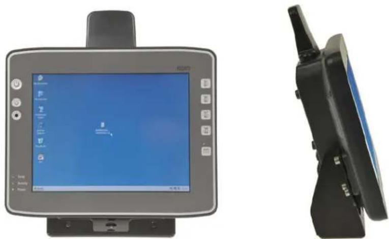
The 8585 and 8595 Vehicle-Mount Computers are multi-function industry computers designed for stationary and mobile use.
- Due to its rugged design (aluminium housing), the device provides effective protection against mechanical, electrical and chemical influences and extreme ambient temperatures.

NOTE The Model 8585 Vehicle-Mount Computer is used as an example throughout the manual, but all specifications, other than dimensions, are also applicable to the Model 8595.
Figure 7-1 The 8585 Vehicle-Mount Computer
natural_image
Front and side views of a remote control device (no visible text or symbols)Device Models
The following models of this Vehicle-Mount Computer are available:
• The 8585 with 10.4" display.
• The 8595 with 12.1" display.
Abbreviations Used for Devices and Accessories
Please note that to save space on the 8585 and supplied accessories, the following abbreviations have been used:
| Abbreviation Meaning | |
| + | DC+ |
| - | DC- |
| Ign Ignition | |
Device/Type identification
Device Type Plate
The device type plate on the 8585 contains the following information:
| 8585or8595 | Describes the vehicle-mount computer with a 10" displayDescribes the vehicle-mount computer with a 12" display |
| SVGA or XGA Display resolution | |
| DC | Type of power supply, the following number indicate the exact type of power supply with input voltage |
| e.g. 24/48Vwith 2.5 A / 1.2 A | Input voltage of the DC power supply with nominal current |
| 1.1 GHz Clock rate of the CPU | |
| S/N ... - 12 digit serial number composed of:- Zebra specific device code (41 stands for the 8585 model range with Intel CPU, 42 stands for the 8585 model range with AMD CPU)- Week of manufacture- Year of manufacture- Six digits for internal identification | |
Technical specifications
Mechanical (8585/8595)
| Housing Rugged aluminium-cast housing with integrated heat sink | |
| Protection class IP 65, IP 66 and IP 67 | |
| ESD safe | |
| Dimensions/Weight:8585: 10.4" : 285 x 230 x 79.5 mm, approx. 2.8 kg8595: 12.1" : 325 x 258.5 x 79.5 mm, approx. 3.5 kg | |
| Display | |
| 8585 | 10.4" SVGA, 400 cd/m2, resistive 5-wire touchscreen, with brightness adjustment |
| 8595 | 12.1" XGA, 400 cd/m2, resistive 5-wire touchscreen, with brightness adjustment |
| Bottom | Cable cover (splash guard) |
| Top Antenna for WLAN | |
8585/8595 AMD: CPU, Cache, RAM (Motherboard)
| CPU | AMD CPU (Advanced Processing Unit) G-T40R |
| Chipset | 1.0 GHz, 512 kB L2 cache |
| Cache | and 1066 MHz memory bus speed |
| RAM 2 GB RAM | DDR3 Technology |
| BIOS(UEF) | AMI Aptio UEFI, 4 MByte serial SPI firmware flash mit ACPI, PnP Programmable in the system, BIOS POST self test |
| Real-time clock Real-time clock with a power reserve of up to 5 years. | |
| Mass storage | Up to 64 GB Flash media, based on SLC technology (single level cell).Advantages: Longer retention time for the data, longer lifetime (by a factor of 1) and a broader temperature range in comparison with MLC technology (multi-level cell). |
| Audio | Integrated speaker. |
| Model No. M1000Speaker/Mic | Optional Speaker/Mic with push-to-talk function. |
Operating System (Optional) for 8585/8595 AMD
| Software Compatibility | Windows Embedded Standard 7 32bit (single-core) and 64bit (dual core)Windows 7 Professional 32bit (single-core) and 64bit (dual core) |
Serial Port
| Serial Port | COM1Max. 115.200 Baud (16550A compatible, 16 byte FIFO), supports RS-232 on an external 9pin D-Sub connectionESD level 4 protected (acc. to EN 61000-4-2)COM1 optionally 5 V |
USB-connection, Service USB
| USB connection 1 USB | 2.0 service (protected under antenna cap)2 x USB 2.0 hostProperties:• USB 2.0 HiSpeed• Fused at 0.5 A per channel• Fused for ESD level 4 (compliant with EN 61000-4-2).For example for mouse, keyboard, USB stick. |
Touchscreen Interface
| Analog Touch Controller | 12bit touch controller for 4/5/8-wire resistive touchscreens with RS232 interface.Drivers available for:• Windows Embedded Standard 7• Windows 7 Professional |
8585/8595 AMD: Network Interface
| Network Controller | Ethernet Intel® 82574 |
| 10/100/1000 MB/s | |
| Network Connection RJ45 plug-in connector | Integrated transmitter |
| Integrated status LEDs |
Power Supply
The device model is displayed on the device type plate.
| DC Power Pack | 12/24 VDC nominal |
| 12/24 VDC | Voltage range: 9 to 36 VDC |
| 30 W internal | Voltage drops of up to 5 V and up to 20 seconds can be bridged |
| Type DC-11 | Bridging of power failures of 5 ms at 12 VDC |
| Start voltage at least 9 VDC | |
| Galvanically isolated | |
| Maximum output: 30 W | |
| Withstands bursts up to 2 kV | |
| Nominal current of 4.2 / 1.0 A | |
| Connection to SELV circuit* only | |
| DC Power Pack | 24/48 VDC nominal |
| 24/48 VDC | Voltage range: 18 to 60 VDC |
| 30 W internal | Voltage drops of up to 5 V and up to 20 seconds can be bridged |
| Type DC-12 | Bridging of power failures of 5 ms |
| Galvanically isolated | |
| Maximum output: 30 W | |
| Withstands bursts up to 2 kV | |
| Nominal current of 2.5 A / 1.2 A | |
| Connection to SELV circuit* only | |
| Power Consumption 8585/10: | typically 20 W |
| Standby: typically 1 W | |
| (8585/10 with DC power pack in standby mode) |
* The SELV circuit is a secondary circuit that is designed and protected so that its voltages will not exceed a safe value both when operating correctly or if a single error occurs.
Power Supply Fuses
The symbol for the fuse is FA. You will find the exact position on the sticker located on the connection plate.
| Power Supply Fuse Type Examples | ||
| DC-11 5 x 20 mm | T 10 A Bussman S505-10A | |
| H / 250 V Wickmann 181-10A | ||
| Power Supply Fuse Type Examples | ||
| or similar devices produced by other manufacturers | ||
| DC-12 5 x 20 mm | T 4 A Bussman S505-4A H / 250 V Wickmann 181-4A | Littelfuse 215 04Siba 70 007 65 4AElu 179200 4Aor similar devices produced by other manufacturers |
Ambient Conditions
| Operating Temperature -30° to +50°C | |
| In accordance with EN 60068-2-1/2 | |
| Storage Temperature -30° to +65 °C | |
| In accordance with EN 60068-2-1/2 | |
| Relative Humidity 10% to 90% @ 40°C non-condensing | |
| In accordance with EN 60068-2-3 | |
| Mechanical Vibration and Shock-Resistance | Class 5M3 according to EN 60721-3-5: 1998 (Land vehicles),5 hrs. noise 3.6 g effective and 36 vibrations with 30 g peaksOr:US Highway Truck according to MIL-STD 810 G: 2000 (Department of Defense),3 hrs. noise 1 g effective and 600 vibrations 20 g peaks in operation |

NOTE For units with an AMD processor: If the ambient temperatures exceed 40^ , the processor comes under high strain or output is extracted externally via peripheral interfaces (USB, serial), the 8595 may switch off or restart under unfavourable conditions.
Corrective action: Ensure sufficient cooling. Supply the connected external peripheral devices from other external sources.
Dimensions 8585/10
Front View
Dimensions without add-ons (in mm).
Figure 7-2 Dimensions 8585 front view
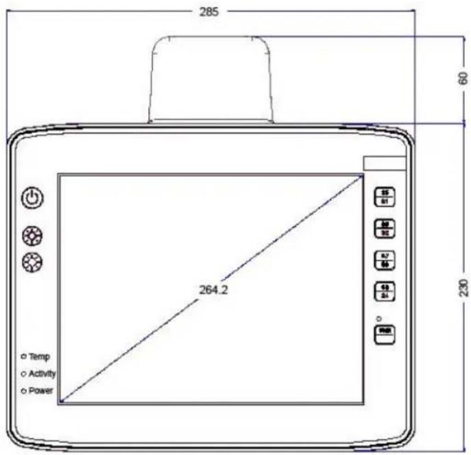
Side View
Dimensions without add-ons (in mm).
Figure 7-3 Dimensions 8585 side view
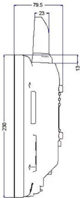
Top View
Dimensions without add-ons (in mm).
Figure 7-4 Dimensions 8585 top view
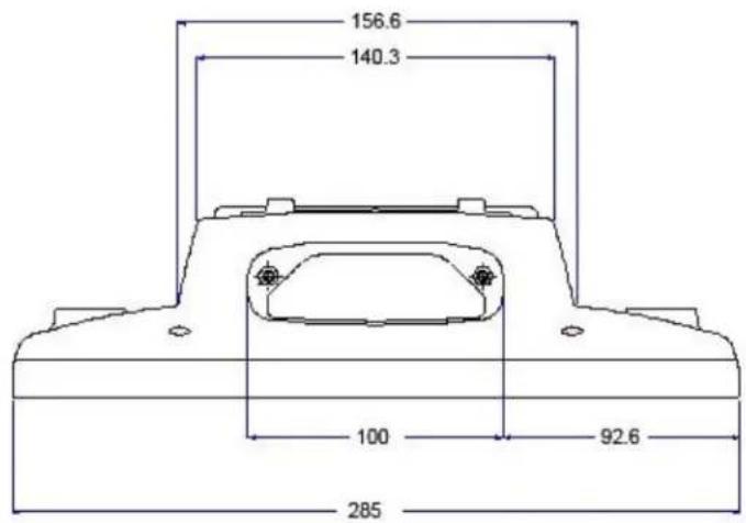
VESA Drill Holes
The VESA drill holes on the 8585 are visible on this diagram. Dimensions without add-ons (in mm).
Figure 7-5 Position of the VESA drill holes
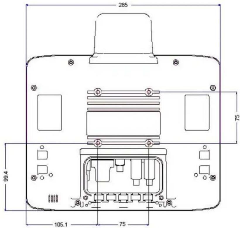
Approvals
Please see Declaration of Conformity on page 1-6 for the list of regulatory approvals.
APPENDIX A ZEBRA CONFIG PROGRAM
Basic Safety Guidelines
Caution: Zebra Config contains important settings for your 8585 and 8595. Incorrect settings, such as those in Property Damage the Automatic Switch-off menu, can disable the functions of your computer. Only qualified technical personnel, e.g. persons qualified in computer/network/system administration may perform Zebra Config settings.
If improper changes of the Zebra Config settings are performed by the customer, this releases Zebra from all liability for warranty claims.
Overview of Functions

NOTE The Zebra Config software automatically recognizes the 8585 type and the installed operating system. The configuration dialog differentiates the various systems and is displayed according to the device.
The sample screen following is an example of the functions that are displayed if the Windows Embedded Standard 7 (WES7) operating system is installed in the device.
Figure A-1 Zebra Config main menu with operating system WES 7
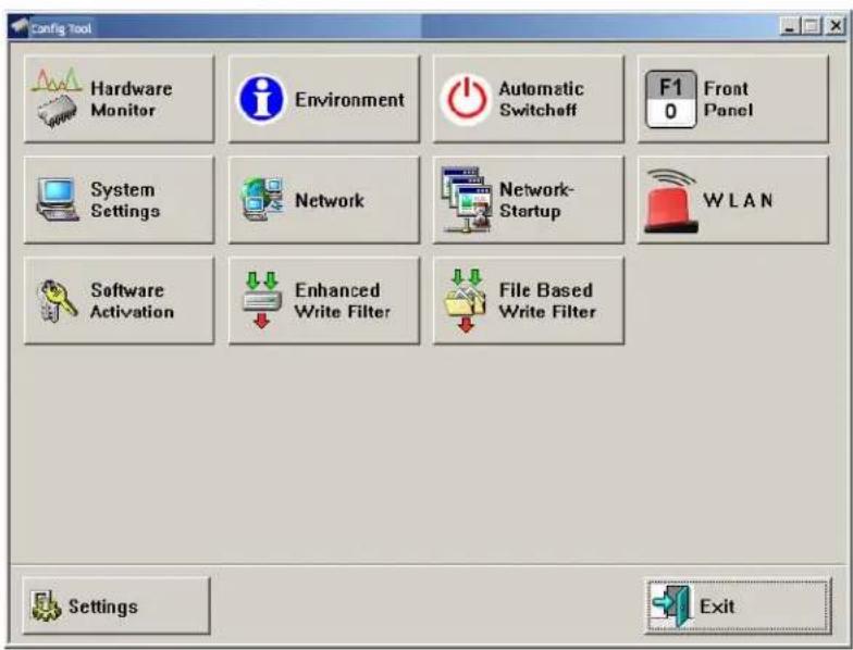
Windows 7 Professional does not support File Based Write Filter. This button is omitted with this operating system.
| Menu Function | |
| Hardware Monitor | Information display: e.g. serial number of the device and current operating temperature. |
| Environment | Information display: Statistics and data on the environment controller, such as 'hard' switch-offs. |
| Automatic Switch-off | Configures the automatic switch-off behaviour (delay time, ignition, etc.). |
| Front Panel Defines the assignment of 8585s optional front panel keys. | |
| System Settings Configures Windows logon, taskbar display etc. | |
| Network Manages IP address and DNS server. | |
| Network Startup Start programs automatically when booting the device. | |
| WLAN Configuration of the WLAN Status Window. | |
| Software Activation | Activates licenses for automatic switch-off and software keyboard and releases them for use on this computer. |
| Enhanced Write Filter Exclusively for MS Windows Embedded operating systems: administers write protection function. | |
| File Based Write Filter | Exclusively for MS Windows Embedded operating systems: administers write protection function. |
| Settings Sets password, language and further default settings for the Zebra Config program. | |
| Exit | Exit Zebra Config program. |
Installation
System Requirements
The following operating systems are supported:
- Windows Embedded Standard 7 (WES 7)
• Windows 7 Professional
Pre-installed on Zebra Computers
In most cases Zebra Config is pre-installed on each 8585 and 8595.
Subsequent Installation
An installation program, Zebra config.exe, is available from the Zebra Help Desk for subsequent installation.
Start the Zebra config.exe from the directory into which it was installed.
Restart the computer once installation is complete. Zebra Config will only be operable following rebooting.
Automatic Installation of Software Keyboard
Zebra software keyboard is automatically installed as part of the Zebra Config installation. If no license is available for this software, the keyboard will only function for three minutes. It then stops working. For further information about the software keyboard, please refer to the instruction manual of the same name.
Files
The following important files are located in the Zebra Config installation directory:
Table A-1 Installation directory files
| ZebraCfg.exe Main program for configuration | |
| Config_Local.cfg Configuration file with Zebra Config settings - all local settings that are not saved directly in the hardware are saved here.More information:See Write WLAN Log File on page A-23 | |
| ZebraKEYBOARD.EXE | Software keyboard main program |
| KEYBOARD.CFG | The layout and functionality of the software keyboard are set here. |
Supported language codes
The following language codes are supported during text file loading. Currently only ENG and GER are available. Other languages can be created as needed (refer to Command line parameters below).
| ENG English CHS Chinese | ||
| GER German KOR Korean | ||
| FRA French DNK Danish | ||
| ESP Spanish JPN | Japanese | |
| SWE Swedish GRC Greek | |||
| ITA Italian | |||
Only ASCII files can be loaded at this time. UNICODE is not supported.
Loading language files
Text files for Zebra Config are loaded when the program is started. If a text file is not available in the desired language, the system default text (in English) is used for the dialogs.
Command line parameters
The parameter MAKETEXT is available to translate software into foreign languages. This means text resources can be exported to *.txt files. Each time a file is created, a message appears prompting the user to confirm it. Simply add the language code to the end of this newly generated text file. For example, ZebraCfg_.txt would then be ZebraCfg_ENG.txt if it contained the English text. During text file generation, files with the same name are automatically overwritten. English is the system default language. It does not need to exist as a text file. The program terminates once the text files have been generated.
Starting the Program
Start Zebra Config via the Windows Programs menu under Start.
Password Check
If a password was entered in the Zebra Config Settings menu, this will be requested when starting the program. The password is case-sensitive; the program terminates after three incorrect entries.
The default password ex works is gold. Please change this in the Settings menu to suit your requirements.
Accessing Config with WES 7
As of software version 3.10, there are two different ways to access Zebra Config from the Start menu in WES 7 based on User Account Control (UAC).
| Read only start program, read-only access |
| Run as Administrator start program, full write access |
FBWF Advice at the Start of the Program
If the hard drive on which the config files are saved is enabled for FBWF, the following message appears at the Zebra Config start-up:
Figure A-2 Zebra Config information: FBWF is activated
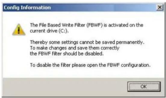
De-activate the FBWF Filter, if necessary.
Hardware Monitor
In the Hardware Monitor menu, 8585 system information is displayed:
• 8585 serial number
- Zebra model
- Installed processor
- Firmware version
• B I O S v e r s i o n
• Inside temperature of the 8585
Figure A-3 8585 Hardware monitor menu
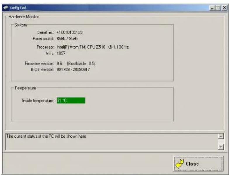
Environment
The environment controller in the 8585 features monitoring and statistics functions. The Environment menu provides information on the measured values.
Information on 8585
Figure A-4 8585 Environment menu
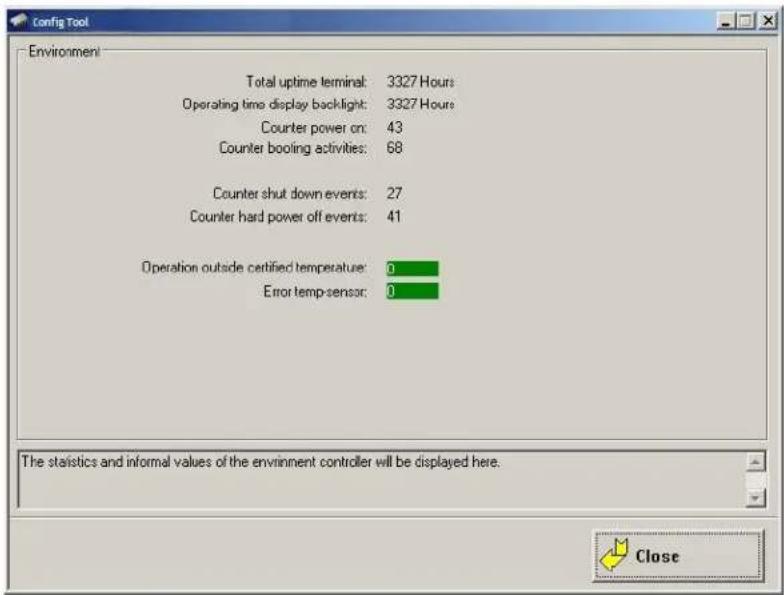
Parameter Description
| Total uptime terminal Total time the device was on | |
| Operating time display backlight Total time that backlighting was on | |
| Counter power on | Shows how often the computer was switched on with the power key |
| Counter booting activities | Shows how often the computer was switched on via the vehicle ignition |
| Counter shut down events Shows how often the computer was switched off via the ignition | |
| Counter hard power off events | Shows how often the computer was turned off using 'hard' switch-off |
| Operation outside certified temperature | Shows how often the computer switched off due to excess temperature |
| Error temp sensor Shows how often temperature sensor errors occurred. If this error message occurs frequently, please send your unit in to be serviced. | |
Automatic Switch-off Configuration Dialog
In the Automatic Switch-off menu, the behaviour of computer switch-on and switch-off is defined.
The top left of the menu shows whether the option Automatic Switch-off is available and activated.
The option can be activated in the Software Activation menu (after purchasing the option).
Caution: Each 8585 has been equipped with an automatic shutdown function. This function has been pre-configured for vehicle use already and governs the power-up and shutdown procedures for the 8585 Damage connected to a car ignition.
The automatic shutdown settings for 8585 devices that are not going to be installed into a vehicle must also be correctly set for the device type!
Figure A-5 Automatic Switch-off menu on 8585
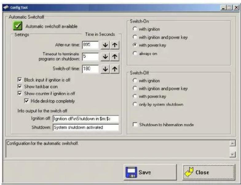
Don't forget to save these settings with the Save button.
Settings
Table A-2 Automatic Switch-off settings
| Parameter Description | |
| After-run time | If you do not want the computer to shut down immediately after switching it off using the ignition or power key, but rather it should remain on for a time, then enter an after-run time (in seconds) here. |
| and | Shutdown timesThe length of time until shutdown consists of two counters: |
| Timeout | 1. After-run time |
| to terminate programs on shutdown | The after-run time begins with the switching off of the ignition. The shutdown counter is displayed on the monitor (according to the settings). In this countdown the after-run time is counted downwards. If the after-run time has elapsed, a message for the shutdown will be displayed in the Shutdown dialog.During this time, the computer can be returned to normal operating status with the ignition.2. Timeout to terminate programsNext, all applications are informed that Windows will shutdown.After this, the timeout begins counting down — but a counter is no longer displayed in the Shutdown dialog. |
| Switch-off time | In order to allow enough time for the system shutdown after the program timeout, set the switch-off time to at least 20 s plus the program timeout. Settings lower than this value will cause a warning to appear when data is being saved. |
| Block input if ignition is off | If the ignition of the connected vehicle is off, all input to the computer may be blocked. |
| Show taskbar icon | Selecting this options creates a symbol for Zebra Config in the taskbar.The symbol indicates the power status as follows:Green: Power status is OK; ignition is on.Flashing yellow and red: The ignition has been switched off and the after-run time is counting down.Red: The computer is in shutdown or switch-off mode.Unable to read power status.Double-click or right-click with the mouse to open a popup menu where Zebra Config can be started. |
| Show counter if ignition is off | A small dialog is displayed in the foreground where a counter counts down the after-run time until shutdown. Depending on the option Block input, a Shutdown button is also shown that allows the user to immediately start the shutdown. |
| Hide desktop completely The d | displayed counter dialog is opened in Fullscreen mode, covering the entire desktop. Large, easy-to-read text is displayed automatically. |
| Info output for the switch-off | Enter any text here for the after-run time counter and the shutdown process. A line break in the text can be entered with '\n'.The after-run time counter is defined in 'm' for minutes and 's' for seconds. These text codes are case-sensitive. |
| Ignition off Text for the display | time |
| Shutdown with ignition Text for | the display time |
Switch-On
| Parameter Description | |
| with ignition | The computer switches on automatically when the ignition is started. It cannot be switched on with the power key. |
| with ignition and power key | The computer can be switched on with the power key if the ignition is on. It cannot be switched on with the power key alone. |
| with power key The 8585 can be switched on with the power key. | |
| always on | The 8585 switches on as soon as it is supplied with power. It is not necessary to press the power key or start the ignition. |
Switch-Off
| Parameter Description | |
| with ignition | Automatic switch-off is activated when the ignition is switched off. |
| with ignition and power key | Automatic switch-off is activated when the ignition is switched off. The power key shortens the defined after-run time and initiates computer shutdown. |
| with power key | The computer is shut down or switched off with the power key (if no automatic switch-off is available, a 'hard' switch-off takes place). |
| only by system shutdown | The computer cannot be switched off using the ignition or the power key; it has to be shut down in the Start menu. |
| Shutdown to hibernation mode | If the computer is switched off using the ignition or the power key, it goes into hibernation mode. When this happens, a copy of the main memory is written to a file, accelerating the startup of the computer. This option must be activated in the power management centre of the computer (Power Properties). |
Front Panel
In the Front Panel menu, the keys (also called soft keys) located on the 8585 front panel can be programmed.
This does not apply to the keys Power on/off, +/- Brightness, and Backlight on/off!
All keys depicted in grey/white can have two assignments. Use [SHIFT] to switch between the assignments.
Character strings cannot be assigned to single keys. Only one character per key is possible. The keys [Alt], [Ctrl] and [Shift] may be used in combination, e.g. [Ctrl] [Alt] [F1].
Configuration Dialog
Figure A-6 8585 Front Panel Keyboard menu
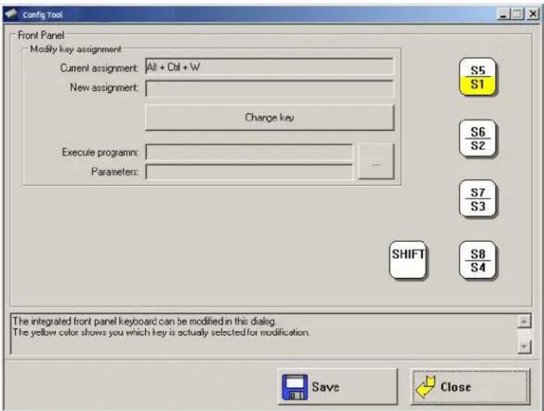
Assigning Front Panel Keys
- Select the key to be changed, it appears in the Current assignment field.
- Press the Change key button. The Define key input dialog appears.
- Press the desired key assignment. The selected key assignment appears in the New assignment field.
- Save these settings with the Save button.
If an assignment is given twice to the same key, a corresponding warning message appears.
Deleting Front Panel Key Assignment
To delete a front panel key assignment, delete the contents of the field and save it with the Save button.
Starting an External Program with the Front Panel Keys
A front panel button is assigned with a program call by using the Execute program and Parameter settings.
- Open the file selection and select a program file (.exe).
- Now the Parameter field can be edited.
If necessary, input the desired call parameter.
- Save the settings.
The front panel button is now assigned the program call; restarting the computer is not necessary.
Common System Settings
In the Common System Settings menu, parts of the Windows System can be configured. The content of this menu differs depending on the operating system.
Windows Embedded Standard 7 and Windows 7 Professional
Figure A-7 Common System Settings
![Config Tool Common System Settings Automatic Windows Logon ✓ Logon automatically as Domain name: User name: Administrator Password: ••••• Logon with Software Keyboard ✓ Show software keyboard at logon Keyboard definition for the logon: C:\Psion\Keyboard.cfg Remote Desktop Logon with SW-Keyboard ✓ Activate support for Remote Desktop Keyboard definition for the logon: Keyboard- / Frontkey Locking ✓ Lock, keyboard and frontkeys Password for keylock (numeric only): Common ✓ Activate this options only if the write protection [EWF] is active ✓ Hide taskbar ✓ Lock Windows task manager ✓ Lock system keys [Ctrl-Esc, Alt-Esc, Alt-Tab, left Windows key] Definition of special Windows system settings. Save Close](/content/2026/06/1164766/images/88828a584ce4f8a43fe5fd159d5e45b363dff9f8919fdf2333a61e47f324624a.jpg)
Automatic Windows Logon
| Parameter Description | |
| Logon automatically as Enable or disable the Automatic Windows Logon. | |
| Domain name | Logon data for the Automatic Windows Logon must be entered. |
| User name | |
| Password | |
Logon with Software Keyboard
| Parameter Description | |
| Show software keyboard at logon | If this check box is selected, the software keyboard is already available to the user upon logging in. |
| Keyboard definition for the logon | A CFG file and hence a particular keyboard layout can be specified for the logon (it may differ from the default keyboard). Changes to this setting are activated only after the computer has been restarted. |
Common
| Parameter Description | |
| Activate this option only if the write protection (EWF) is active | This setting applies to Windows Embedded Standard 7.Here you can define whether the following options relating to the taskbar, task manager and system keys are to be valid only when EWF write protection is active.For example: When the system administrator is working on the computer and has deactivated EWF write protection, the taskbar, task manager and system keys are available. These cannot be accessed by users working with EWF write protection. |
| Hide taskbar Taskbar is hidden. | |
| Lock Windows task manager Task manager cannot be accessed. | |
| Lock system keys The keys [Ctrl-Esc], [Alt-Esc], [Alt-Tab] and the left Windows key are locked. | |
Remote Desktop Logon with SW-Keyboard
| Parameter Description | |
| Activate support for Remote Desktop | After a remote access to the current computer, the software keyboard can be activated for logging back in. |
| Keyboard definition for logon The CFG | file for the software keyboard is specified, e.g. “C:\Zebra\Keyboard.cfg” |
Keyboard / Front Key Locking
| Parameter Description | |
| Lock keyboard and front keys | Using this setting, all keyboard inputs/key inputs on the 8585 can be locked.·Front panel buttons·External keyboard·Software keyboard (via touch screen)Locking is only active after restarting the computer. |
| Password for key lock(numeric only) | Locking is only activated if a max. 20 character long keyword is defined. For this only numbers are used.During activated lock, the password dialog for releasing the keyboard appears when pressing (or creating) any key (except for power/brightness keys). The password can only be entered using the touch screen and the keys displayed in the dialog.Password request for locked keyboard lock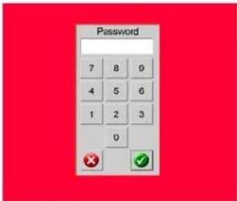 Only the administrator can remove the lock during successful locking. Only the administrator can remove the lock during successful locking. |
WES 7
Automatic Windows Logon
| Parameter Description | |
| Logon automatically as | Enable or disable the Automatic Windows Logon. |
| Domain name | Logon data for the Automatic Windows Logon must be entered. |
| User name | |
| Password | |
Software Keyboard
| Parameter Description | |
| Show software keyboard at logon | If this check box is selected, the software keyboard is already available to the user upon logging in. |
| Keyboard definition for the logon | A CFG file and hence a particular keyboard layout can be specified for the logon (it may differ from the default keyboard). Changes to this setting are activated only after the computer has been restarted. |
| Display in user session If this | checkbox is activated, the software keyboard for the system in operation is displayed. |
| Keyboard definition for the user session | A CFG file and hence a particular keyboard layout can be specified for the user session (it may differ from the default keyboard). Changes to this setting are activated only after the computer has been restarted. |
Keyboard / Front Key Locking
| Parameter Description | |
| Lock keyboard and front keys | Using this setting, all keyboard inputs/key inputs on the 8585 can be locked.Front panel buttonsExternal keyboardSoftware keyboard (via touch screen)Locking is only active after restarting the computer. |
| Password for key lock(numeric only) | Locking is only activated if a max. 20 character long keyword is defined.For this only numbers are used.During activated lock, the password dialog for releasing the keyboard appears when pressing (or creating) any key (except for power/brightness keys). The password can only be entered using the touch screen and the keys displayed in the dialog.Password request for locked keyboard lock Only the administrator can remove the lock during successful locking. Only the administrator can remove the lock during successful locking. |
Network Settings
Common
In the Common menu under Network Settings, you can make settings for the network adapter (LAN and WLAN).
Find information about settings for the network adapter currently selected in the Current Settings window.
The System Settings button opens the Windows dialog for networks.
Figure A-8 Network Settings: Common menu
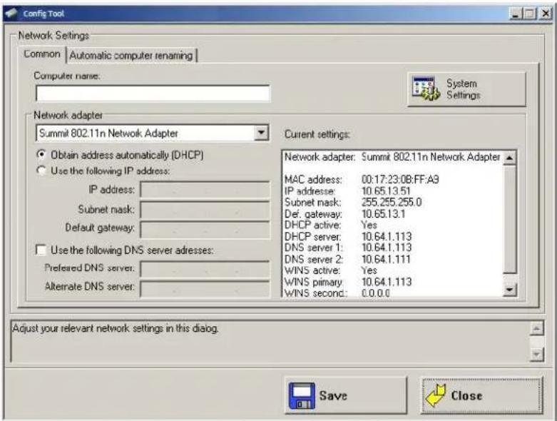
Computer name
The 8585 host name can be changed.
Network Adapter
| Parameter Description | |
| Selection list Select the Network adapter | |
| Obtain address automatically (DHCP) | With this setting, the network configuration is obtained from a DHCP server. |
| Use the following IP address | Here the IP address, subnet mask and default gateway can be entered manually. |
| Use the following DNS server addresses | Here the DNS servers to be used can be entered manually. |
Automatic Computer Renaming
The settings in the Automatic Computer Renaming menu under Network Settings are used for the automatic assignment of computer names. Allocation of different computer names is supported by entering the MAC address.
Figure A-9 Network Settings: Automatic Computer Renaming
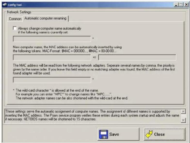
Network Startup
You can define programs in this menu which should be started after a network connection is successfully established with a server (after every boot of the operating system).
Figure A-10 Network Startup
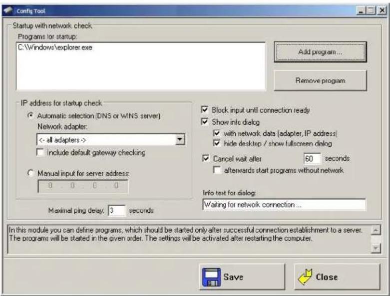
Autostart Programs
Multiple programs can be specified. The programs are started in the order given. The settings are activated only after the computer is restarted.
| Parameter Description | |
| Add program | The Windows file selection dialog is shown and you can select a program. |
| Remove program Remove a selected program. | |
IP Address for Startup Check
| Parameter Description | |
| Automatic selection (DNS or WINS server) of network adapter | The desired network adapter can be specified here.Possible selections are:All adaptersCOM2 VPN adapterIntelR PRO / 100VE Network Connection |
| Include default gateway in check | If this checkbox is checked, then the default gateway is also included when searching for an IP address. |
| Manual input of the server address | If a server address is specified here, the programs are only started when the computer has established a connection to that IP address. |
| Maximum ping time Time to | wait for a response after running a ping. |
Parameter Description
| Block input until connection established | Until the network connection is established, no input can be performed on the computer. |
| Show waiting dialog | A waiting dialog can be shown, optionally with network information and in full-screen mode. |
| Stop waiting after 5 seconds | If no network connection has been established, the wait can be stopped after the time given here. |
| Then start programs without network | The programs can also be started without a network connection. |
| Info text in waiting dialog | The text entered here will be displayed on the waiting dialog. |
WLAN
In this menu, you can configure whether a WLAN status window will be displayed on the 8585, with information about signal strength and quality of the WLAN connection.
Information on the WLAN Status Window
Figure A-11 WLAN Status Window
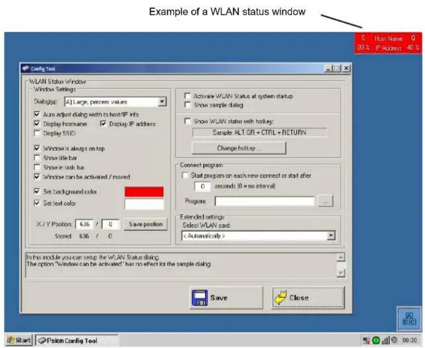
Color Legend for Signal Strength Color Legend for Quality
| Red = signal strength poor Yellow = signal strength fair | |
| Green = signal strength good Red = poor quality | |
| Yellow = fair quality Green = good quality | |
Signal Strength and Quality
| Parameter Description | |
| S = Signal strength | This value provides information about the strength of the signal received by the computer.The signal strength can be displayed as a dBm value, in percentages, or as a diagram, depending on the configuration selected in the WLAN dialog. |
| Q = Quality This value | provides information about the quality of the signal received by the computer.The quality can be displayed as a dB value, as a percentage, or as a diagram, depending on the configuration selected in the WLAN dialog. |
| Host name | The host name is displayed according to the setting in the WLAN menu. |
| IP address | The IP address of the 8585 is displayed according to the setting in the WLAN menu. |
Basic Legend for Signal Strength
Signal strength alone says nothing about the quality of the signal. The quality depends on the ratio of signal to noise (SNR = Signal/Noise Ratio = RSSI, Radio Signal Strength Indicator).
The following values are a good rule of thumb:
- Signal strengths less than -70 dBm are good.
• Quality between 10 and 20 dB is good.

IMPORTANT These values are only approximate and depend on many factors (different sensitivity of receivers, data bandwidth, etc.)
WLAN Status Window Settings Dialog
Figure A-12 WLAN Status Window dialog type
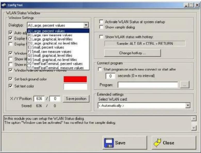
Window Settings
| Parameter Description | |
| Dialog type | In the selection list, select the desired design for the WLAN status window. The signal strength and quality can be displayed as dBm values, percentages, or a bar chart. |
| Auto adjust Dialog width to host/IP info | The width of the WLAN status window can be defined as a fixed value. Otherwise, it depends on the length of the host name and the IP address. |
| Display host name Shows the | host name in the WLAN status window. |
| Show IP address Shows the | IP address in the WLAN status window. |
| Display SSID | SSID (Service Set Identifier) is displayed in the WLAN Status Window. |
| Windows is always on top | The WLAN status window will always be displayed on top of other windows. |
| Show title bar Display the WL | LAN status window with a title bar. |
| Show in task bar The WLAN | status window will appear in the task bar. |
| Window can be activated / moved | The position on the WLAN status window on the screen can be moved. If the title bar is displayed, the window can be activated. |
| Set background colour The b | background colour of the WLAN status window is selected. Click the colour field to see a palette of all available colours. |
| Set text color | The text color of the WLAN status window is selected. Click the color field to see a palette of all available colors. |
| X/Y position The position of t | the WLAN status window on the screen is defined here. The window will appear at this position after every program start. |
| If you move the example dialog around the screen using the mouse pointer, the current coordinates will automatically be entered. | |
| Then click on Save position. | |
Parameter Description
| Activate WLAN status at system startup | This checkbox must be activated for the WLAN status window to be displayed. |
| Show sample dialog | If clicked, the settings made in the dialog will be demonstrated in an example window. |
| Show WLAN status with hotkey | The WLAN status window can be turned on and off with a 8585 front panel key defined here.To be able to use this setting and as a result the front panel key (Hotkey), the 8585 must be restarted. |
Connect Program
Parameter Description
| Start program on each new connect or start after... | This setting is used to start any arbitrary software program.The program may optionally be started:after every entry into the WLAN area or periodically; if necessary, enter the time interval.If a WLAN connection exists, the program is started at the specified intervals.Note:The prerequisite is that there is a functioning WLAN connection!An application example: The 8585 on a forklift has an online connection to the warehouse management database. If the forklift leaves the WLAN area, this online connection is interrupted. To receive updated data immediately after entering the WLAN area again, the Connect Program function is used to start a database update automatically. |
Program Enter the program to be started here.
Extended Settings
Parameter Description
| Select WLAN card | Detect the radio card automatically or select it from the list (see also WLAN status window and radio cards next page). |
Finally, don't forget to Save!
WLAN Status Window and Radio Cards
The WLAN status window works exclusively with radio cards which support WMI. The WMI class is configured in "config_local.cfg" in the line "Noiseselect_01".
The WMI selection string in the format: NoiseSelect_XX=Card-Name,SELECT *....
For XX, substitute a number from 01 to 20; at most 20 different WLAN cards can be supported.
For the card name, a few characters at the start of the WLAN adapter name are enough (not case sensitive).
The full SELECT string is then specified, separated by a comma.
Write WLAN Log File
To optimize the WLAN network, or e.g. to analyse errors in roaming, a WLAN log file can be generated using the Zebra Config program.
-
For this, edit the Config_local.cfg file in the Zebra directory of the 8585 (e.g. with Notepad).
-
The entry
"Debug_Logging=0"entry is located by default in section CfgWLANStatus
0 means: no log file will be generated.
1 means: a log file will be generated and written to the Zebra directory. Filename of the log file: WLAN_DebugLog.txt.
- Restart the computer to activate the setting and generate the log file.
Caution: Property Damage
Only generate WLAN log files temporarily for analysis purposes. Afterwards make sure to set the 'Debug_Logging' entry to '0'.
Otherwise system errors are a threat, since if the EWF is deactivated storage media will be filled with log files (size of a WLAN log file: up to 50 MB. When this size is reached, the Zebra Config automatically creates BAK files, which are sequentially numbered.)
Figure A-13 Example of a WLAN log file
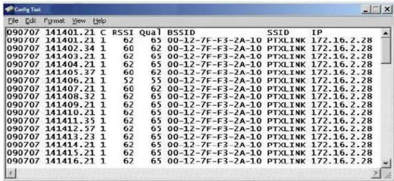
Information in the WLAN Log File
The following basically applies:
- Only the information which is displayed in the WLAN status window is written in the WLAN log file (according to the definition in the Zebra Config menu WLAN Status Window).
- The maximum size of the WLAN log file is 50 MB. When this size is reached, the Zebra Config automatically creates BAK files, which are sequentially numbered.
The WLAN Log file contains eight columns with the following information
The column heading is displayed after every 100 lines.
- Date
• Time (to one-hundredth of a second)
• C= Connected
0 means no, 1 means yes
- RSSI signal strength
- Signal quality
- BSSID Mac address of current connected access point
• SSID of WLAN network - IP address of 8585
Software Activation
In the Software activation menu, options such as automatic switch-off and software keyboard can be activated. If these options are purchased at a later date (after the 8585 delivery), customers receive an activation key or a license file, which must be entered here.

NOTE The automatic switch-off function in the 8585 is always available and does not need to be activated.
Figure A-14 Software Activation menu
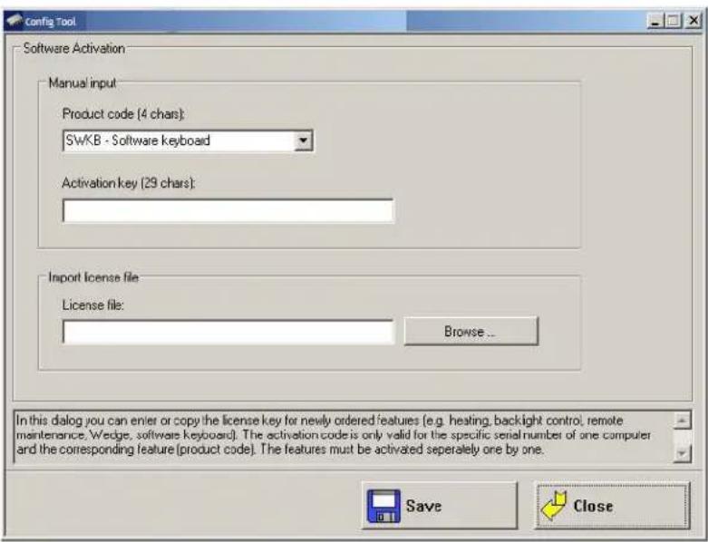
Activate Automatic Switch-off
Activate the automatic switch-off as follows:
- Activate the Product code in the line AOFF Automatic switch-off.
- Enter the activation key you received with the purchase of the option.
Or. Click Search file under Import license file and load the license file that contains this key. - Save the settings.
Activate Software Keyboard
Activate the software keyboard as follows:
-
Activate the Product code in the line SWKB Software keyboard.
-
Enter the activation key you received when you purchased the option.
Or. Click Search file under Import license file and load the license file that contains this key.
- Save the settings.
After licensing, a Keys file is automatically created for the software keyboard and is stored in the Keys directory. If this file is accidentally deleted, the software keyboard will no longer function. After three minutes running time it switches itself off.
Enhanced Write Filter

NOTE The Enhanced Write Filter menu is only relevant for the embedded operating systems (Microsoft Windows Embedded Standard 7 and Windows XP Embedded)!
If EWF is not installed, no changes can be performed.
Write protection is enabled and managed in the Enhanced Write Filter menu. This allows you to protect the system against modification of any kind. All write accesses or modifications on an activated EWF drive will be discarded with the next restart.
EWF settings are not saved or loaded to import/export configurations (see Settings on page A-8).
Figure A-15 Enhanced Write Filter menu
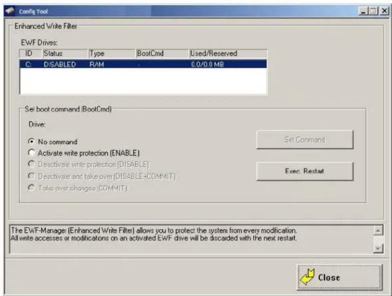
The computer's EWF drives are displayed in the EWF Drives field (there is usually only one). The settings below apply to the EWF drive selected here.
Set Boot Command (BootCmd)
| Parameter Description | |
| No command The set boot commands are deactivated again. | |
| Activate write protection (ENABLE) | Activates write protection: All system changes are written exclusively to the main memory; they are discarded when the computer is restarted.To activate this setting, reboot the computer! |
| Deactivate write protection (DISABLE) | Disables write protection.To activate this setting, reboot the computer! |
| Deactivate and take over (DISABLE+COMMIT) | This setting is a combination of Deactivate write protection and Take over changes: Write protection is deactivated; changes are applied. |
| Take over changes Temporarily deactivates write protection in order to commit current changes to the system. Once finished, write protection is immediately active again. | |
- Click Set Command to apply the settings.
- Click the Exec. Restart button to restart the computer and activate the settings.
File Based Write Filter

NOTE The File Based Write Filter menu is relevant for the embedded operating systems with the exception of Windows Professional 7!
The FBWF Menus: Current and Target Status of the Installation
The left column of the FBWS menu always shows the currently installed FBWF configuration; the right column shows the newly defined configuration after the computer is restarted.
Figure A-16 FBWF configuration menu
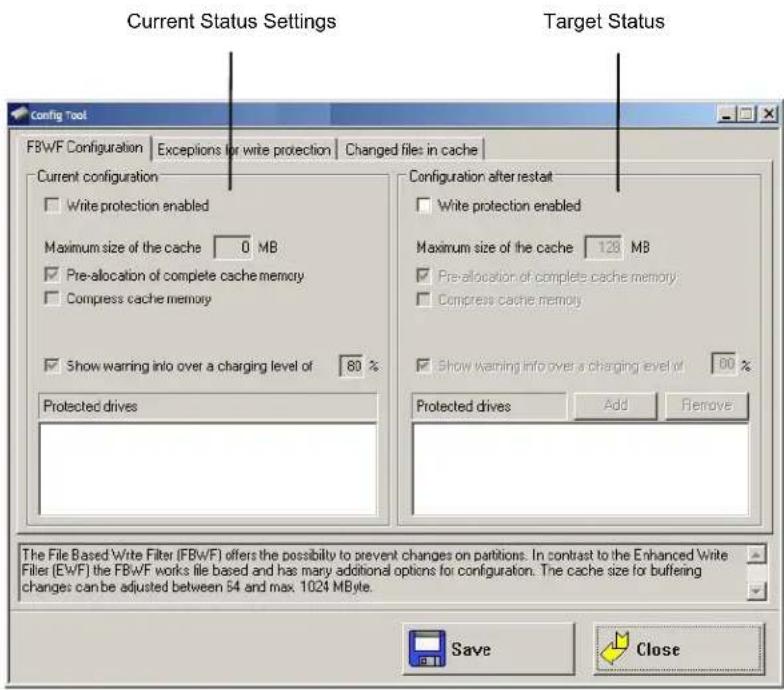
- When the desired configuration is complete: Don't forget to save the settings.
FBWF Configuration
The File Based Write Filter (FBWF) offers the possibility to protect a partition from changes. In contrast to the Enhanced Write Filter (EWF), the FBWF filters on a file basis and offers many additional options for configuration. The cache for intermediate storage of the changes can be set for between 64 and 1024 MB.
Current Configuration
The currently valid FBWF settings are displayed.
Table A-3 Configuration after restart
| Parameter Description | |
| Write protection enabled | Enable FBWF; the computer must be rebooted to activate the settings. |
| Maximum size of the cache | Memory size available for the overlays. Entries between 64 and 1024 MB are possible. |
| Pre-allocation of complete cache memory | Maximum memory is not dynamic, but statically reserved in advance. |
| Compress cache memory Memory content is compromised | |
| Show warning info over a charging level of | Enter the percentage load factor of the reserved memory at which the warning message should be displayed. |
| Protected drives Add/Remove | The hard drives listed here are protected from changes. After clicking on Add or Remove, a list of hard drives is displayed. |
- When the desired configuration is complete: Don't forget to save the settings.
Exceptions for Write Protection
Here you can define exceptions for write protection. Entire directories or individual files can be specified. Changes to files on the exception list are written directly to the file system, as usual.
The left column of the menu shows the currently set FBWF configuration; the right column shows the newly defined configuration after the computer is restarted.
Figure A-17 Exceptions to write protection
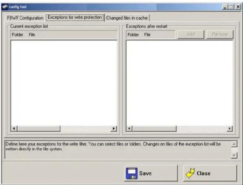
Current Exception List
The currently valid settings are displayed.
Table A-4 Exceptions after Restart
| Parameter Description | |
| Add/remove | After clicking on Add or Remove, a list of hard drives and files is displayed. |
- When the desired configuration is complete: Don't forget to save the settings.
Modified Files in the Cache
When FBWF is active, files are shown here that are protected by FBWF and that were changed during the run time.
The following is possible here:
- apply changes and write them to the file system
• or restore the original status of the file and delete it from the cache.
Figure A-18 Modified files in the cache
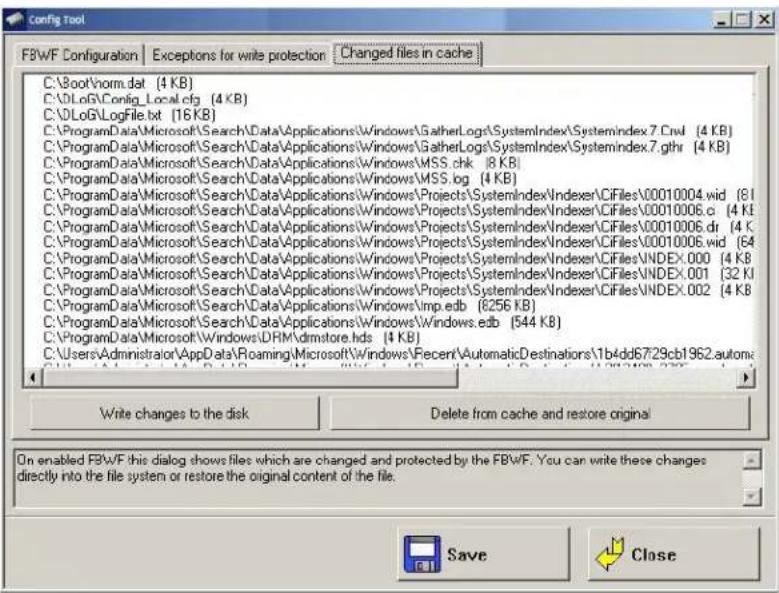
Procedure:
- Select the individual lines in the list.
- Press the Write changes to the disk button if the changed data that is still in the cache is to be written to the respective hard drive.
- Or select Delete file from cache and restore original if the modified file in the cache should be deleted.
Error messages
FBWF Error (1)
Figure A-19 FBWF error: File is in the FBWF cache
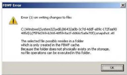
| Explanation: | Files could not be written to the files, as they did not physically exist. |
| With OK the file is skipped, the procedure Write changes to data media is carried out for the next file on the list. | |
| With Cancel, the procedure Write changes to data media is interrupted. |
FBWF Error (53)
Figure A-20 FBWF error: For files that are currently being accessed
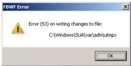
| Explanation: | Files which are currently being accessed cannot be written to data media.With OK the file is skipped, the procedure Write changes to data media is carried out for the next file on the list.With Cancel, the procedure Write changes to data media is interrupted. |
Settings
In this menu, Zebra Config is configured with respect to password, language etc.
Figure A-21 Settings menu
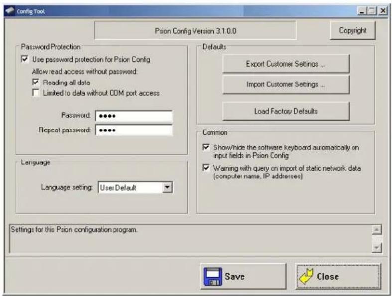
Password Protection
| Parameter Description | |
| Use password protection for Zebra Config | A password can be activated to allow access to programs.Enter a password and repeat the entry in the Repeat password field.This is case-sensitive. |
| Allow read access without password: | |
| Reading all data Zebra C | config can be started without a password. It is possible to read all data, but no changes may be made to the settings. |
| Limited to data without COM port access | A password is not required to start Zebra Config. Reading of data is limited: The Environment, Automatic Switch-off and Front Panel menus are not available. |
Language
| Parameter Description | |
| Language setting | The language of the Zebra Config menus is defined. The default is always the system language of the computer. If no language file is available for this language, texts will be displayed in English. Only those languages may be selected for which language files (ZebraCfg*_.*.txt) are available in the Config EXE directory. |
Defaults
| Parameter Description | |
| Export customer settings | With this function, all Zebra Config settings can be exported to a Config text file. Each export file is displayed with an info header (see Info Header of an Export File on page A-33.The export file can be imported to other 8585 to maintain identical settings on all computers. |
| Import customer settings | Those files generated with the export function can be selected for import. It is not possible to import the local Config_Local.cfg. Before the import, a message tells you not to mix AC-DC configurations, as this can block the device.In the event that a mandatory software key for activating diverse options on a PC is missing, this is reported in a corresponding error message.Please note: If options are released in the imported Config setting, which are missing on this computer, a corresponding error message is displayed.Caution: Property DamageDuring import not all data is checked for validity; rather the data is saved in the way that it is defined in the import file. False information could lead to failure of 8585 (such as malfunctions, data loss, equipment damage etc.). |
| Load factory defaults Here | default settings can be loaded that are saved in a file named:FactoryDefault_.cfg.This file can only be generated by Zebra service with an internal program.The AC-DC configuration warning does not appear, as it is assumed that this is taken into account at installation.If the file is not available, an error message about a 'defect' file appears. |
Common
| Parameter Description | |
| Show/hide the software keyboard automatically on input fields in Zebra Config | The software keyboard starts automatically when Zebra Config is started. When the cursor is placed in an input field, it is always displayed.A file named Keyboard.cfg must exist in the software keyboard installation directory; otherwise an error message appears.If the keyboard is started by Zebra Config, it is also terminated when Zebra Config is closed. The software keyboard version 1.5 or higher is mandatory for this. An error message is displayed when errors occur.The message is only visible after logging on. |
| Warning with query on import of static network data (computer name, IP addresses) | If static IP addresses (when DHCP is disabled) and/or a computer name are imported, a warning with corresponding security query may appear. |
Command Lines Parameter IMPORT (only for administrators)
The parameter IMPORT is available for import using batch job (Zebra Config V 2.3 and higher).
Example: ZebraCfg IMPORT=
The CFG file to be imported must be generated using export from Zebra Config.
The CFG filename must contain the entire path (or at least "\" for the current directory).
Other parameters for control of the batch import are:
| NONET | The data from the config module “network” will NOT be imported. |
| STATNET | Static IP addresses will be imported and set during batch import.Default: Static IP addresses will NOT be imported. |
Please note:
- To activate the imported data the computer must be restarted.
- Output redirection functions in a file with “>”, however the output is still additionally written to the console window.
Caution:
Property
Damage
NO warning/request appears when using the COM2!
NO warning appears with information about the non-permitted mixing of configurations between AC and DC devices.
Info Header of an Export File
The info header of an export file contains the following information:
A - 34 8585/8595 Vehicle-Mount Computer User Guide
;
; Zebra Config export file
; Exported from computer: MPC5XPEMBSP2
; Hardware serial-number: 205004056587
; Export timestamp (YMD): 2005/06/18 20:30:13
[General]
ZebraCfgExportVer=1
ZebraCfgExportSNR=205004056587
INDEX
Numerics
24-key keypad....5-1, 5-2
8585
chipset 4-6
DC power supply 3-2
dimensions, front view 7-6
display size.... vii
external connectors 2-5
front keys. 4-2, 4-3
front view....7-6, 7-7
LEDs. 4-3
operating states 4-4
powering up/down. 2-7
power key 2-8,4-3
shift key 4-4
side view 7-8
special keys 4-4
specifications 7-2
supply cable 2-7
top view 7-9
8595
display size.... vii
specifications 7-2
vehicle-mount model vii
A
abbreviations, labels for devices/accessories ..... 7-2
adaptor cables (ignition & screen blanking) ..... 2-5
analog touch controller 7-4
antenna....3-5
cap 3-5, 3-6
cap graphic 3-6
configuring transmitting power 2-3
installation distance....3-5
regulations, Germany....2-3
Transmit power configuration....2-3
WLAN, minimum distance to 3-5
approvals 1-6
audio 7-3
Automatic Switch-off
activate ....A-24
Configuration Dialog....A-6
operation 4-7
Autostart programs....A-18
B
battery, vehicle 1-3
BIOS 7-3
brightness control 4-3
C
cable
ignition adaptor 2-5
screen blanking adaptor 2-5
supply....2-5
cable cover.... 3-5, 6-2
cache, modified files ......A-28
cache, motherboard....7-3
calibration, touchscreen 4-2
CE Marking 1-4
chipset....4-6,7-3
cleaning. 4-2
housing 6-1
touchscreen 6-3
clock....7-3
COM1 power supply 4-5
Command line parameters
Zebra Config program A-4
Command Lines parameters
IMPORT (only for administrators) .....A-33
computer renaming, automatic....A-17
Config_local.cfg file....A-23
connections
antenna cable 3-5
DC voltage supply....2-6
external 2-5
external devices 2-7
RJ45 port 4-6
RS-232 4-6
USB 3-5
connectors
external detailed view 2-5
construction
resistance....4-1
type 4-1
cooling through the supply of fresh air 3-1
CPU 7-3
D
data transmission 4-7
data transmission via LAN/Ethernet. 6-1, 6-2
DC
power pack....7-5
power supply connector drawing....2-6
voltage supply connector 2-5
DC+ connecting cable....3-2
DC- signal reference 2-6
Declaration of Conformity....1-6
device
models.... vii, 7-2
type identification 7-2
type plate 7-2
dimensions
8585 front view 7-6
8585 top view....7-9
display
protection, 8585 ...... 2-4
specifications 7-3
disposal 6-3
dynamic loading 3-1
E
electrical installation.... 3-2
emergency shutdown 1-3
error messages, Zebra Config program ..... A-29
F
FBWF
advice A-4
configuration ......A-27
FCC
Declaration 1-5
user information 1-5
Files Needed (touch installation dialog) 4-2
Flash, installing operating system 4-5
forklift installation 3-2, 3-3, 3-4
Front Panel
Zebra Config program....A-10
Front Panel Keys
assigning A-11
assignment, deleting ..... A-11
configuration 2-1
description 4-3
starting external programs....A-11
fuse 7-5
DC+ connecting cable 3-2
ignition connecting cable. 3-2
type 7-5
G
Germany, antenna regulations 2-3
ground, logic and shield 3-2
ground bolt. 3-3
H
housing....7-3
humidity 7-6
|
ignition
connecting cable 3-2
vehicle 2-6
ignition adaptor cable 2-5
K
keyboard 5-1
small 5-1
keypad, 24-key 5-1, 5-2
keys, special 4-4
L
Lair Connection Manager
password input 2-4
Laird Connection Manager.... 2-3
icon 2-4
Wi-Fi icon 2-3
WLAN configuration 2-3
LAN/Ethernet cable 4-7
LEDs 4-3
logic ground.... 3-2
logon, Windows....A-12
M
M1000, Speaker/Mic model 4-6, 7-3
maintenance 6-1
mass storage 7-3
mechanical dynamic loading....3-1
vibration and shock-resistance....7-6
memory effect, TFT display 2-4
mobile application on vehicles....6-3
modes of operation....4-7
motherboard....7-3
mounting....6-2
assembly steps 3-4
instructions 3-1
mouse 5-2
N
network
adaptor....4-6
connection....7-4
controller 7-4
interface....7-4
0
operating conditions 7-6
emergency 1-3
modes 4-7
states 4-4
system 4-4, 4-5
system installation....4-5
system software....7-4
system special features 4-5
temperature 7-6
P
packaging...... viii
password, Laird Connection Manager ..... 2-4
password, read access without .....A-31
power consumption 7-5
key 2-8,4-3
supply....1-3, 3-2, 6-2, 7-5
fuses 7-5
protection 1-3
safety 1-3
powering up/down the 8585....2-7
programs, Autostart....A-18
Protection Class 1-2, 3-5
protective antenna cap....3-5
R
radio frequencies, transmission....1-5 performance, WLAN....2-2
RAM....7-3
read access without password ....A-31
real-time clock....7-3
regulatory approvals 1-6
repairs....1-4
RJ45 port 4-6, 4-7
RS-232 connections....4-6
RTTE directive....1-4
s
scanner bracket....5-2
scanners 5-2
screen blanking adaptor cable....2-5
SELV circuit 3-2
serial port 4-5, 7-4
bar code scanners 4-5
printers....4-5
Service USB Interface 3-5
Service USB interface 3-5, 3-6
shield ground 3-2
SHIFT key 4-4
shock-resistance....7-6
Signal Strength, Zebra Config program....A-20
signal strength and quality....A-20
Software Keyboard activate ....A-24 logon ....A-12
sound controller....4-6
speaker....4-6
Speaker/Mic 4-6, 7-3
special keys 4-4
splash guard 3-5
strain relief rail....3-5
supply cable....2-5, 2-7
SVGA 7-2
T
technical specifications 7-3
temperature operating....7-6 operating state....4-4 storage....7-6
text conventions .... x
TFT display, protection 2-4
touch driver (util/atouch/vernr) 4-2
Touch for MS Windows Embedded 4-2
Touch for MS Windows XP Embedded 4-2
touchscreen
calibration....4-2
cleaning....4-1, 6-1, 6-3
controller 7-4
driver (util/atouch/vernr) 4-2
interface 7-4
operation....4-1
safety 4-1
software 4-1, 4-2
specifications 4-1
using 6-3
troubleshooting 6-1
prevention....6-2
U
USB
connection 7-4
connection, Service USB 7-4
recovery stick....5-2
stick 5-2
uses of 8585....1-1
util/atouch/vernr touch driver 4-2
V
vehicle
applications 3-2
battery, charging 1-3
ignition....2-6
installation.... 3-2, 6-2
VESA drill holes 7-10
VGA
adaptor 4-6
W
Wi-Fi icon 2-3
Windows logon....A-12, A-14
WLAN
antenna distance....3-5
card (PCIe minicard) 5-3
configuration 2-3
log file, Zebra Config program ..... A-23
radio performance 2-2
settings 2-2
status display....2-1
Status Window / Radio Card, Zebra Config program. A-22
status Windows settings dialog, Zebra Config program....A-21
Write Protection ...... A-28
X
XGA....7-2
Z
Zebra Config program....4-8
8585 settings 2-1
AOFF Automatic switch-off....A-24
automatic switch-off 4-8
Command line parameters....A-4
common system settings A-11
computer name....A-16
Configuration Dialog A-10
connect program....A-22
current exception list A-28
Enhanced Write Filter menu....A-25
environment A-6
error messages....A-29
exceptions for Write Protection ..... A-28
export file info header A-33
extended settings....A-22
FBWF Menus....A-26
File Based Write Filter menu A-26
Front Panel....A-10
Front Panel Keys description 2-1
functions overview ...... A-1
hardware monitor A-5
information on 8585....A-6
installation A-3
installation of Software Keyboard A-3
IP Address, startup check....A-18
keyboard / front key locking ..... A-14, A-15
language....A-31
loading language files ...... A-4
main menu....A-1
menu 2-2
network adapter ...... A-16
settings A-16
startup A-17
password A-4
protection A-31
remote desktop logon with SW-keyboard ..... A-13
safety guidelines....A-1
set boot command (BootCmd)....A-26
settings ...... A-31
shutdown times....A-8
software activation A-24
software keyboard.....A-15
starting external program with Front Panel Keys.A-11
supported language codes....A-3
SWKB Software keyboard....A-25
system requirements .....A-3
Windows 7 and WES 7 A-4, A-14
WLAN 2-1, A-19
log file....A-23
status window....A-19

bar
| Category | Value | |---|---| | Category 1 | 100 | | Category 2 | 100 | | Category 3 | 100 | | Category 4 | 100 | | Category 5 | 100 | | Category 6 | 100 | | Category 7 | 100 | | Category 8 | 100 | | Category 9 | 100 | | Category 10 | 100 |
ZEBRA
Zebra Technologies Corporation
Lincolnshire, IL U.S.A.
http://www.zebra.com
Zebra and the stylized Zebra head are trademarks of ZIH Corp., registered in many jurisdictions worldwide. All other trademarks are the property of their respective owners.
© 2015 ZIH Corp and/or its affiliates. All rights reserved.
- VEHICLE-MOUNT COMPUTERS
- 8585/8595 VEHICLE-MOUNT COMPUTERS USER GUIDE
- Copyright
- Disclaimer
- Bluetooth
- Revision History
- TABLE OF CONTENTS
- Chapter 1: Approvals and Basic Safety Guidelines
- Chapter 2: Basic Operation
- Chapter 3: Installing the Computer
- Chapter 4: Operation
- Chapter 5: Accessories
- Chapter 6: Maintenance and Troubleshooting
- Chapter 7: Device Description and Technical Specifications
- Appendix A: Zebra Config Program
- ABOUT THIS GUIDE
- Overview of the 8585 and 8595 Vehicle-Mount Computers
- Device Models
- Scope of Delivery
- Packaging
- Removing the Protective Film from the Display
- Returning Your Device
- About the 8585 / 8595 Vehicle-Mount Computer User Manual
- For Qualified Personnel
- Keep this Manual
- Text Conventions
- CHAPTER 1 APPROVALS AND BASIC SAFETY GUIDELINES
- Always Install, Operate, and Maintain the Unit Properly
- Safety
- Intended Usage
- Initial Operation of the Device
- Installation/Initial Operation
- Risk of injury during transit or installation
- Choice of Location: Observe the Protection Class
- Supply of Fresh Air: Avoid overheating the unit
- Install an easily accessible disconnecting device
- Laying Power Supply Cables: Observe the local installation regulations
- Ensure that no persons are injured in case the mounting bracket breaks
- Power Supply
- External Devices
- Repairs Only
- CE Marking
- RTTE Directive 1999/5/EC
- Special Rule/Restriction
- Regulatory Summary
- FCC User Information
- Declaration of the Federal Communications Commission
- WARNING!
- Transmission of Radio Frequencies
- Use care in airplanes or in clinical/medical areas
- Caution with pacemakers
- Country Roaming
- Declaration of Conformity
- Regulatory Information for China
- Class A Product Warning
- Chinese Warning Statement for Class A ITE
- Warning
- Quality Certificate in Chinese when the Factory has ISO 9001 Certification
- Zebra Config: Front Keys, WLAN, Automatic Switch-off
- WLAN Settings
- Radio Performance
- Antenna Solutions for Use in Germany
- Laird Connection Manager for WLAN Configuration
- Admin Password
- Protecting the TFT Display from the Memory Effect
- Connectors
- Overview of External Connectors
- Adaptor Cables
- DC Voltage Supply Connector
- Explanation:
- Connecting External Devices
- Powering Up the 8585
- Powering Down the 8585
- CHAPTER 3 INSTALLING THE COMPUTER
- Overview
- Follow and Retain the Mounting Instructions
- Mechanical Dynamic Loading
- Cooling Through the Supply of Fresh Air
- Vehicle Applications (such as forklifts)
- Electrical Installation
- WARNING! PAY CLOSE ATTENTION TO THE FOLLOWING WARNINGS!
- WARNING! Individual vehicle requirements and any installed supplementary electronic systems on the vehicles must be reviewed to ensure 8585/8595 grounding is compatible - follow vehicle manufacturers recommendations.
- Wiring Vehicle Power to the 8585/8595
- WARNING! Applying a voltage above the input voltage rating or reversing polarity may result in permanent damage to the 8585/8595 and will void the product warranty.
- Position of the 8585 in the Vehicle
- Overview of the Assembly Steps
- Cable Cover (splash guard)
- Protection class
- Strain Relief
- Minimum Distance to WLAN Antenna
- Antenna Cap and Service USB Interface
- Unfasten antenna cap from unit and refasten it:
- CHAPTER 4 OPERATION
- Touchscreen
- Construction Type and Resistance
- Operation
- Cleaning
- Touch for MS Windows Embedded Standard 7
- Installation
- Calibration
- Front Keys and LEDs
- Power Key
- Manual Brightness Control
- LEDs
- Special Keys
- Shift Key
- Operating States
- Operating System
- Pre-installed on Flash
- Installing on Flash
- Special Features of the Operating Systems
- Serial Port
- COM1 as a Power Supply
- Serial Port Printers
- Serial Port Bar Code Scanners
- Tips and Tricks
- Internal Devices
- Chipset
- VGA Adaptor
- Onboard Sound Controller
- Network Adaptor (10/100/1000)
- Left LED (Green)
- Right LED (Amber)
- Problems with Data Transmission via LAN/Ethernet
- Automatic Switch-off
- Modes of Operation
- Automatic Switch-off Process
- Configuration with Zebra Config Program
- CHAPTER 5 ACCESSORIES
- Keyboard
- SMALL Keyboard
- 24-key Keypad
- Scanner Bracket
- Mouse
- USB Stick
- USB Recovery Stick
- Scanners
- WLAN Card (PCIe MiniCard)
- Microphone (Voice Kit)
- CHAPTER 6 MAINTENANCE AND TROUBLESHOOTING
- Maintenance
- Cleaning the Housing
- Touchscreen Cleaning
- Troubleshooting
- Data Transmission via LAN/Ethernet
- Images for AMD Devices are not Compatible with Intel Devices
- 8585/8595 AMD: Switch Off/Restart
- Common Mistakes in Usage
- Intel Images are not Compatible with AMD Devices
- Powering Up/Down
- Cable Cover
- Mounting/Installation
- Mobile Application on Vehicles
- Using the Touchscreen
- Cleaning the Touchscreen
- Disposal
- CHAPTER 7 DEVICE DESCRIPTION AND TECHNICAL SPECIFICATIONS
- General
- Abbreviations Used for Devices and Accessories
- Device/Type identification
- Device Type Plate
- Technical specifications
- Mechanical (8585/8595)
- 8585/8595 AMD: CPU, Cache, RAM (Motherboard)
- Operating System (Optional) for 8585/8595 AMD
- USB-connection, Service USB
- Touchscreen Interface
- 8585/8595 AMD: Network Interface
- Power Supply Fuses
- Ambient Conditions
- Dimensions 8585/10
- Front View
- Side View
- Top View
- VESA Drill Holes
- Approvals
- APPENDIX A ZEBRA CONFIG PROGRAM
- Basic Safety Guidelines
- Overview of Functions
- System Requirements
- Pre-installed on Zebra Computers
- Subsequent Installation
- Automatic Installation of Software Keyboard
- Files
- Supported language codes
- Loading language files
- Command line parameters
- Starting the Program
- Password Check
- Accessing Config with WES 7
- FBWF Advice at the Start of the Program
- Hardware Monitor
- Environment
- Information on 8585
- Automatic Switch-off Configuration Dialog
- Settings
- Switch-Off
- Front Panel
- Configuration Dialog
- Assigning Front Panel Keys
- Deleting Front Panel Key Assignment
- Starting an External Program with the Front Panel Keys
- Common System Settings
- Windows Embedded Standard 7 and Windows 7 Professional
- Automatic Windows Logon
- Logon with Software Keyboard
- Common
- Remote Desktop Logon with SW-Keyboard
- WES 7
- Software Keyboard
- Keyboard / Front Key Locking
- Network Settings
- Computer name
- Network Adapter
- Automatic Computer Renaming
- Network Startup
- Autostart Programs
- IP Address for Startup Check
- WLAN
- Information on the WLAN Status Window
- Signal Strength and Quality
- Basic Legend for Signal Strength
- WLAN Status Window Settings Dialog
- Window Settings
- Connect Program
- Extended Settings
- WLAN Status Window and Radio Cards
- Write WLAN Log File
- Information in the WLAN Log File
- The WLAN Log file contains eight columns with the following information
- Software Activation
- Activate Automatic Switch-off
- Activate Software Keyboard
- Enhanced Write Filter
- Set Boot Command (BootCmd)
- File Based Write Filter
- The FBWF Menus: Current and Target Status of the Installation
- FBWF Configuration
- Current Configuration
- Exceptions for Write Protection
- Current Exception List
- Modified Files in the Cache
- Procedure:
- Error messages
- FBWF Error (1)
- FBWF Error (53)
- Command Lines Parameter IMPORT (only for administrators)
- Please note:
- Info Header of an Export File
- A - 34 8585/8595 Vehicle-Mount Computer User Guide
- INDEX
- Numerics
- A
- B
- C
- D
- E
- F
- G
- H
- |
- K
- L
- M
- N
- 0
- P
- R
- s
- T
- U
- V
- W
- X
- Z
- ZEBRA
Brand : ZEBRA
Model : 8585
Category : Printer