ZEUS52E2K - Inverter CONCEPTRONIC - Free user manual and instructions
Find the device manual for free ZEUS52E2K CONCEPTRONIC in PDF.

User questions about ZEUS52E2K CONCEPTRONIC
0 question about this device. Answer the ones you know or ask your own.
Ask a new question about this device
Download the instructions for your Inverter in PDF format for free! Find your manual ZEUS52E2K - CONCEPTRONIC and take your electronic device back in hand. On this page are published all the documents necessary for the use of your device. ZEUS52E2K by CONCEPTRONIC.
USER MANUAL ZEUS52E2K CONCEPTRONIC
ZEUS52E1K / ZEUS52ES1K
ZEUS52E2K / ZEUS52ES2K
ZEUS52E3K / ZEUS52ES3K
IMPORTANT SAFETY INSTRUCTIONS
This manual contains important instructions. Please read and follow all instructions carefully during installation and operation of the unit. Read this manual thoroughly before attempting to unpack, install, or operate the UPS.
CAUTION! The UPS must be connected to a grounded AC power outlet with fuse or circuit breaker protection. DO NOT plug the UPS into an outlet that is not grounded. If you need to power-drain this equipment, turn off and unplug the unit.
CAUTION! The battery can power hazardous components inside the unit, even when the AC input power is disconnected.
CAUTION! The UPS should be placed near the connected equipment and easily accessible.
CAUTION! To prevent the risk of fire or electric shock, install in a temperature and humidity controlled indoor area, free of conductive contaminants. (Please see specifications for acceptable temperature and humidity range).
CAUTION! (No User Serviceable Parts): Risk of electric shock, do not remove cover. No user serviceable parts inside. Refer servicing to qualified service personnel.
CAUTION! (Non-Isolated Battery Supply): Risk of electric shock, battery circuit is not isolated from AC power source; hazardous voltage may exist between battery terminals and ground. Test before touching.
CAUTION! To reduce the risk of fire, connect the UPS to a branch circuit with 10 amperes (1000 / 1500 / 2000) / 16 amperes (3000) maximum over-current protection in accordance to CE requirement.
CAUTION! The AC outlet where the UPS is connected should be close to the unit and easily accessible.
CAUTION! Please use only VDE-tested, CE-marked mains cable, (e.g. the mains cable of your equipment), to connect the UPS to the AC outlet.
CAUTION! Please use only VDE-tested, CE-marked power cables to connect any equipment to the UPS.
CAUTION! When installing the equipment, ensure that the sum of the leakage current of the UPS and the connected equipment does not exceed 3.5mA.
CAUTION! The 1000 / 1500 / 2000 / 3000 / Battery module models are only qualified maintenance personnel may carry out installations.
CAUTION! Do not unplug the unit from AC Power during operation, as this will invalidate the protective ground insulation.
CAUTION! To avoid electric shock, turn off and unplug the unit before installing the input/output power cord with a ground wire. Connect the ground wire prior to connecting the line wires!
CAUTION! Do not use an improper size power cord as it may cause damage to your equipment and cause fire hazards.
CAUTION! Wiring must be done by qualified personnel.
CAUTION! DO NOT USE FOR MEDICAL OR LIFE SUPPORT EQUIPMENT! Under no circumstances this unit should be used for medical applications involving life support equipment and/or patient care.
CAUTION! DO NOT USE WITH OR NEAR AQUARIUMS! To reduce the risk of fire, do not use with or near aquariums. Condensation from the aquarium can come in contact with metal electrical contacts and cause the machine to short out.
CAUTION! Do not dispose of batteries in fire as the battery may explode.
CAUTION! Do not open or mutilate the battery, released electrolyte is harmful to the skin and eyes.
CAUTION! A battery can present a risk of electric shock and high short circuit current. The following precaution should be observed when working on batteries
-
Remove watches, rings or other metal objects.
-
Use tools with insulated handles.
CAUTION! The unit has a dangerous amount of voltage. When the UPS indicators is on, the units may continue to supply power thus the unit's outlets may have a dangerous amount of voltage even when it's not plugged in to the wall outlet.
CAUTION! Make sure everything is turned off and disconnected completely before conducting any maintenance, repairs or shipment.
CAUTION! Connect the Protection Earth (PE) safety conductor before any other cables are connected.
WARNING! (Fuses): To reduce the risk of fire, replace only with the same type and rating of fuse.
DO NOT INSTALL THE UPS WHERE IT WOULD BE EXPOSED TO DIRECT SUNLIGHT OR NEAR A STRONG HEAT SOURCE!
DO NOT CONNECT DOMESTIC APPLIANCES SUCH AS HAIR DRYERS TO UPS OUTPUT SOCKETS!
SERVICING OF BATTERIES SHOULD BE PERFORMED OR SUPERVISED BY PERSONNEL KNOWLEDGE OF BATTERIES A AD THE
REQUIRED PRECAUTIONS. KEEP UNAUTHORIZED PERSONNEL AWAY FROM BATTERIES!
INSTALLING YOUR UPS SYSTEM
UNPACKING
(1) UPSx1; (2) User's manual x1; (3) Input power cord (EU/UK) x2; (4) USB cable x1; (5) RS232 cable x1
INSTALLING YOUR UPS SYSTEM
HARDWARE INSTALLATION GUIDE
-
Battery charge loss may occur during shipping and storage. Before using the UPS, it's strongly recommended to charge batteries for four hours to ensure the batteries' maximum charge capacity. To recharge the batteries, simply plug the UPS into an AC outlet.
-
Connect your computer, monitor, and any externally-powered data storage device (Hard drive, Tape drive, etc.) into the outlets only when the UPS is off and unplugged. DO NOT plug a laser printer, copier, space heater, vacuum, paper shredder or other large electrical device into the UPS. The power demands of these devices will overload and possibly damage the unit.
-
To protect a fax machine, telephone, modem line or network cable, connect the telephone or network cable from the wall jack outlet to the jack marked "IN" on the UPS and connect a telephone cable or network cable from the jack marked "OUT" on the UPS to the modem, computer, telephone, fax machine, or network device.
-
Press the ON switch to turn the UPS on. If an overload is detected, an audible alarm will sound and the UPS will continuously emit one beep per
second. For resetting the unit, unplug some equipment from the outlets. Make sure your equipment carries a load current within the unit's safe range, (refer to the technical specifications).
- This UPS is equipped with an auto-charge feature. When the UPS is plugged into an AC outlet, the battery will automatically charge, even when the unit is switched off.
- To maintain an optimal battery charge, leave the UPS plugged into an AC outlet at all times.
- Before storing the UPS for an extended period of time, turn the unit OFF. Then cover it and store it with the batteries fully charged. Recharge the batteries every three months to ensure good battery capacity and long battery life. Maintaining a good battery charge will help prevent possible damage to the unit from battery leakage.
- The UPS has one USB port (default) and one Serial port that allows connection and communication between the UPS and any attached computer running the Power Master software. The UPS can control the computer's shutdown during a power outage through the connection while the computer can monitor the UPS and alter various programmable parameters.
Note: Only one communication port can be used at a time. The port not in use will automatically become disabled or the serial port will be disabled if both ports are attached.
- To avoid electric shock, turn the unit OFF and disconnect the unit from utility power before hardwiring the UPS (in/out power cord). The in/out power cord MUST be grounded.
BASIC OPERATION
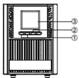
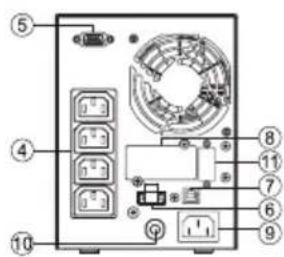
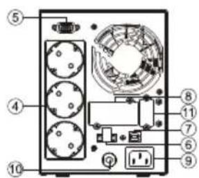
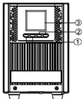
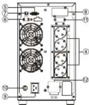
POWER MODULE FRONT/REAR PANEL DESCRIPTION
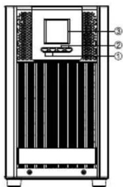
1. Power On/Off Button
Master ON/OFF for the UPS.
2. Function Buttons
.,Scroll up, scroll down, select and cancel LCD menu.
3. Multifunction LCD Readout
Indicate status information, settings and events.
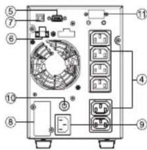
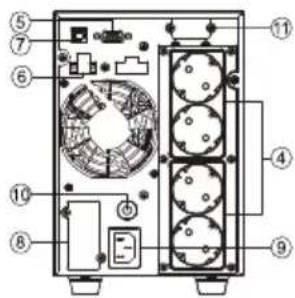
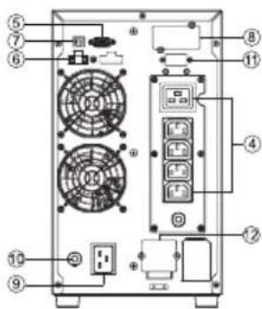
4. Battery Backup & Surge Protected Outlets
Provide battery backup and surge protection. They ensure power is provided to connected equipment over a period of time during a power failure.
5. Serial Port
Serial port provides communication between the UPS and the computer. The UPS can control the computer's shutdown during a power outage through the connection while the computer can monitor the UPS and alter its various programmable parameters.
6. EPO (Emergency Power Off) Connector
Enable Power-Off in emergency from a remote location.
7. USB port
This is a connectivity port which allows communication and control between the UPS and the connected computer. It is recommended to install the Power master software on the PC/Server connected with the USB cord.
8. SNMP/HTTP Network slot
Slot to install the optional SNMP card for remote network control and monitoring.
9. AC Input Inlet
Connect the AC Power cord to a properly wired and grounded outlet.
10. Input Circuit Breaker
Provide input overload and fault protection.
11. Extended Runtime Battery Module Connector(only for long run models)
Connect to additional external battery modules.
12. Output Terminal Block
Connect to your equipment.
text_image
Technical diagram of a device with labeled components, showing front, top, and side viewsZEUS52E1K ZEUS52ES1K
text_image
Labeled diagram of a computer tower rear panel with numbered components and portsZEUS52E1K
text_image
Labeled diagram of a computer rack with numbered components for identificationZEUS52ES1K
text_image
Technical diagram of a device with labeled components, showing front panel, screen, and base with numbered parts.ZEUS52E2K ZEUS52ES2K
text_image
Labeled diagram of an electronic device rear panel with numbered components for identificationZEUS52E2K
text_image
Technical diagram of a computer tower with numbered components for identificationZEUS52ES2K
text_image
Technical diagram of a server rack with labeled components including monitor, fan, and drive unitZEUS52E3K ZEUS52ES3K
text_image
Diagram of a computer rack with labeled components including fans, switches, and drive unitsZEUS52E3K
text_image
Technical diagram of a server rack with numbered components and fan layoutZEUS52ES3K
SOFTWARE INSTALLATION
Power Master management software provides a user-friendly interface for your power systems. The graphic user-interface is intuitive and displays essential power information at a glance. Please follow procedure below to install the software.
Installation procedure:
Download Power Master from the website: hp://www.powermonitor.soware/
Double-click the file and follow the installation steps.
When your computer restarts, the Power Master software will appear as a blue icon located in the system tray.
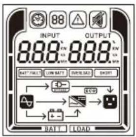
LCD Panel
text_image
INPUT 888 888 BATT/FAULT LOW BATT OVERLOAD SHORT BATT LOADOPERATION MODE LCD DISPLAY
| Operation mode | Description | LCD display | Operation mode | Description | LCD display | |
| Line mode | Utility will provide energy to loads. It will also charge the battery at the same time. | 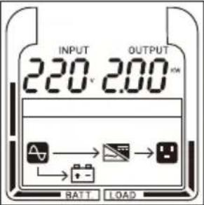 | Battery mode | The unit will provide output power from battery. | 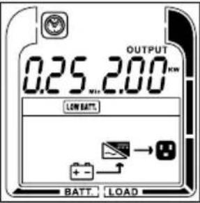 | |
| ECO mode | When the input voltage is within voltage regulation range, UPS will bypass voltage to output for energy saving. | 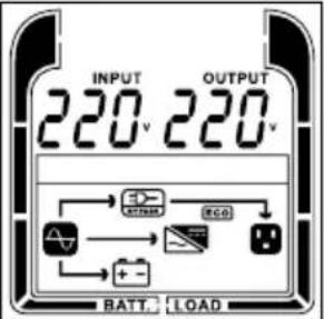 | Bypass mode | When the input voltage is within bypass voltage range, UPS will bypass voltage to output. | 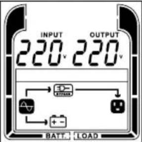 | |
| Converter mode | When input frequency is within 40Hz to 70Hz, the UPS can be set at a constant output frequency, 50Hz or 60Hz. | 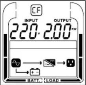 | Standby mode | Utility will charge the battery and no output voltage until switch on the UPS. | 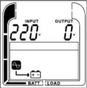 | |
| Warning mode | The UPS is warning because of overload. | 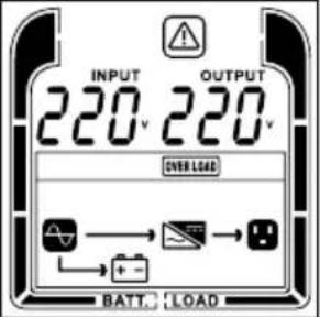 | Fault mode | The UPS goes to fault mode because output is short. | 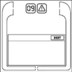 | |
LCD DISPLAYS 6 PAGES IN TOTAL :
| 1 | Left : ACINPUT(Voltage) VRight :OUTPUT(Voltage)V | 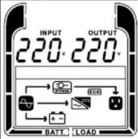 | 2 | Left :INPUT(Frequency) HzRight :OUTPUT(Frequency) Hz |  |
| 3 | Left : W loadPercentage(%)Right :OUTPUTXXX W | 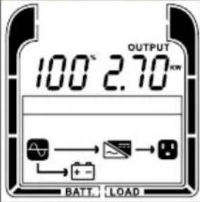 | 4 | Left : VA loadPercentage(%)Right :OUTPUTXXX VA | 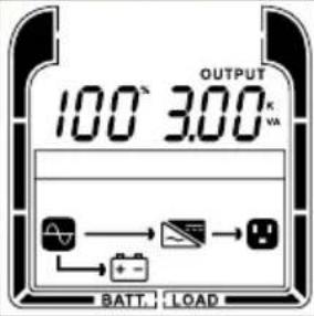 |
| 5 | Left : BatteryCapacityPercentage(%)Right : Battery voltage(v) | 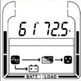 | 6 | Left : BackupTime(min)Percentage(%)Right : Battery voltage(v) | 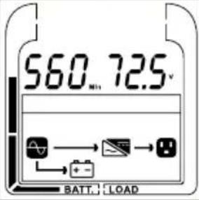 |
EVENT ID DESCRIPTIONS
| Event ID | Description of Cause |
| 01 | Bus Start Fail: DC-DC converter or bus sensing circuit failed. |
| 02 | Bus Volt High: DC-DC converter failed. |
| 03 | Bus Volt Low: DC-DC converter failed. |
| 04 | Bus Unbalanced: DC-DC converter failed. |
| 06 | INV Start Fail: Inverter circuit failed. |
| 07 | INV Volt High: Inverter circuit or output voltage sensing circuit failed. |
| 08 | INV Volt Low: The load may be too heavy or inverter circuit failed. |
| 09 | INV Short: The inverter circuit failed. |
| 11 | Bat Volt High: The external battery module connection is wrong, or the charger failed. |
| 12 | Bat Volt Low: Batteries failed. |
| 14 | Over Load: UPS is overloaded. |
| 18 | Fan Fail: The ventilation hole has been covered, or the fans can't work. |
| 19 | Over Temperature: High ambient temperature, or the ventilation hole has been covered. |
| 62 | Bat low: Battery voltage low. |
| 64 | Over Load warning: UPS is overload. |
| 66 | EPO Off: Missing the EPO connection |
| 68 | High Temperature: High ambient temperature, or the ventilation hole has been covered. This is shown only when start up UPS. |
BUTTON OPERATION
| Button | Operation Description |
| ON | Press this button to turn on UPS. In line mode, ECO mode, or converter mode, press the "ON" button for 5 seconds to activate the battery test. |
| OFF | Press this button to turn off UPS.* |
| ENTER | Press and hold this button for 5 seconds to get into setting mode while in bypass mode, or standby mode.In setting mode, press this button to confirm selection, or press this button for long time to exit setting mode and saving changes. Press this button to scroll up in the LCD menu. |
| ESC | In setting mode, press this button to display next selection, or press this button for long time to exit setting mode without saving changes. Press and hold the "ESC" button for 5 seconds to disable and enable buzzer alarm.Press this button to scroll down in the LCD menu. |
| ENTER + ESC | Switch to bypass mode: When the main power is normal, press these two buttons simultaneously for 5 seconds, then UPS will enter to bypass mode. |
LCD SETTINGS CONFIGURATION
There are 9 UPS settings that can be configured by the user.
- Press and hold the "ENTER" button for 5 seconds to activate the setting mode.
The first configuration parameter will be displayed on the LCD screen.
Note: The manual settings programming mode can ONLY be invoked while UPS is in Bypass mode or Standby mode. To make UPS on Standby mode or Bypass mode, connect utility power to UPS and do not turn on UPS.
- Press the "ENTER" button to select the setting you want to configure.
- Press the "ESC" buttons to scroll through the different parameters and select the parameter you want.
- Press the "ESC" button for 5 seconds to cancel and exit setting mode. Press the "ENTER" button for 5 seconds to save all the settings you just do and exit setting mode.
| Setting item | Configure Submenu | Available Settings | Default Setting |
| 001 | Output Voltage | =[208V] [220V] [230V] [240V] | 220V |
| 002 | Output Frequency | = [50Hz][60Hz] | 50Hz |
| 003 | ECO Mode * | [0%] (Disable) [10%][15%] (Enable) | 0% |
| 004 | Bypass Mode ** | [DIS] (Disable) [ENA] (Enable) | Enable |
| 005 | Converter Mode | [DIS] (Disable) [ENA] (Enable) | Disable |
*) When operating in ECO Mode, the efficiency of UPS is higher than that in online mode, but transfer time should not be 0ms
**) When operating in Converter Mode, the frequency of output should be always 50Hz or 60Hz, but load capacity will be derated by 40%.
*) This function would be set as 0% when Converter Mode is enabled.
**) UPS has no bypass when Converter Mode is enabled.
MAINTENANCE
Storage
To store your UPS for an extended period, cover it and store with the battery fully charged. Recharge the battery every three months to ensure battery life.
Replacement Batteries
Please refer to the front side of the UPS for the model number of the correct replacement batteries. For battery procurement, contact your local dealer.
Battery Disposal
Batteries are considered hazardous waste and must be disposed of properly. Contact your local government for more information about proper disposal and recycling of batteries. Do not dispose of batteries in fire.
TECHNICAL SPECIFICATIONS
| Model | ZEUS52E1K/ZEUS52ES1K | ZEUS52E2K/ZEUS52ES2K | ZEUS52E3K/ZEUS52ES3K |
| Capacity (VA/W) | 1000VA/900W | 2000VA/1800W | 3000VA/2700W |
| Configuration | |||
| Form Factor | Tower | ||
| Energy-saving Technology | Yes, ECO Mode Efficiency ≧95% | ||
| Input | |||
| Voltage Range | 110~300Vac ± 5% for 1000/1500/2000/3000VA model @ 0~50% Load±5% | ||
| 140~300Vac ± 5% for 1000/1500/2000/3000VA model @ 50~70%Load±5% | |||
| 160~300Vac ± 5% for 1000/1500/2000/3000VA model @ 70~80%Load±5% | |||
| 180~300Vac ± 5% for 1000/1500/2000/3000VA model @80~100%Load±5% | |||
| Frequency Range | 40~70Hz | ||
| Power Factor | 0.99 | ||
| Cold Start | Yes | ||
| Output | |||
| Output Voltage | 208/220/230/240Vac±1% | ||
| Output Waveform | Pure Sine Wave | ||
| Output Frequency | 50 / 60Hz (Auto-Sensing or Configurable) ±0.5Hz | ||
| Transfer Time(Typically) | 0ms | ||
| Rated Power Factor | 0.9 | ||
| Harmonic Distortion | THD < 3% at Linear Load, < 5% at Non-linear Load @ Nominal Input | ||
| Crest Factor | 3 : 1 | ||
| ECO Mode Voltage Regulation | ±10%, ±15% (Configurable) | ||
| Protection | |||
| Overload Protection | Line Mode: 105~110% Warning, transfer to bypass after 10min. | ||
| 110%~130% Warning, transfer to bypass after 1min. | |||
| >130% Warning, transfer to bypass after 3s. | |||
| Battery Mode: 105~110% Warning, shutdown after 1min. | |||
| 110%~130% Warning, shutdown after 30s. | |||
| >130% Warning, shutdown after 3s. | |||
| Short Circuit Protection | UPS Output Cut off Immediately or Input Fuse / Circuit Breaker Protection | ||
| Battery | |||
| Battery Type | (2)12V/9AH | (4)12V/9AH | (6)12V/9AH |
| Recharge Time | 4 Hours (inside batteries) | ||
| Charge current | 1.0A(MAX) | ||
| Status Indicators | |||
| LCD Screen | Graphic LCD | ||
| Audible Alarms | Battery Mode, Battery Low, Overload, UPS Fault, Replace Battery, Bypass Mode Charger Failure /Over Charged, Fan failure, EPO active | ||
| Environment | |||
| Operating Temperature | 32°F to 104°F (0°C to 40°C) | ||
| Operating Relative Humidity | 20 to 90% Non-Condensing | ||
| Management | |||
| On-Device Features | Selt Test, Auto-Charge, Auto-Restart, Auto-Overload Recovery | ||
| Connectivity Ports | (1) Serial Port (RS232), (1) USB Port, | ||
| SNMP/HTTP Cable | (1) Expansion Port (With optional card) | ||
| Software | |||
| Power Management Software | Power Master | ||
| Physical | |||
| Dimensions | 140x191x327mm | 151x225x390mm | 196x342x416 |
| Net Weight | 10.1Kg | 15.3Kg | 21.3Kg |
*) Within 50/60Hz±8% by default, the output frequency is synchronization with input mains. User can adjust the acceptable range for output frequency (±1, 2, 3, 4, 5, 6, 7, 8, 9, 10%). When input frequency is out of synchronization window but within 40-70Hz, UPS can stay in line mode and output frequency is regulated at 50/60Hz+0.5% with load derating by40%.
TROUBLE SHOOTING
| Problem | Possible Cause | Solution |
| O/P Overload | Your equipment requires more power than the UPS can provide. If the UPS is in Line Mode then it will transfer to Bypass Mode; if the UPS is in Battery Mode it will shut down. | Shut off non-essential equipment. If this solves the overload problem, the UPS will transfer to normal operation. |
| Battery Mode | UPS is operating on battery power. | Save your data and perform a controlled- shutdown. |
| Battery Low | UPS is operating on battery power and will be shutting down soon due to extremely low battery voltage. | UPS will restart automatically when acceptable utility power returns. |
| EPO OFF | Missing the EPO connection. | Check the EPO connection. |
| Over Temperature | High ambient temperature. | 1. Shut down UPS. Restart UPS to Check the fan for operation and if the ventilation hole has been covered2. Contact your dealer for repair.1. Shut down UPS2. Your attached equipment may have problems, please remove them and check again. |
| Output Short | Output short circuit. | |
| Bus Fault | Internal DC bus voltage is too high or too low. | 1. Shut down UPS2. Contact your dealer for repair. |