Zepher 4 C2 - Uncategorized R-Go Tools - Free user manual and instructions
Find the device manual for free Zepher 4 C2 R-Go Tools in PDF.

User questions about Zepher 4 C2 R-Go Tools
0 question about this device. Answer the ones you know or ask your own.
Ask a new question about this device
Download the instructions for your Uncategorized in PDF format for free! Find your manual Zepher 4 C2 - R-Go Tools and take your electronic device back in hand. On this page are published all the documents necessary for the use of your device. Zepher 4 C2 by R-Go Tools.
USER MANUAL Zepher 4 C2 R-Go Tools
natural_image
Technical line drawing of a mechanical arm assembly mounted on a wall-mounted device, with no visible text or symbols.circular monitor arm
R-Go Caparo 4 D2 &
R-Go Zepher 4 C2
Tips for healthy screen use 3
What's in the box?
Setup Single Monitor Arm
Smart Stop™
Setup Dual Monitor Arm

text_image
Green QR code image containing encoded data, no visible text or symbols beyond the matrix patternWatch How To Set Up
Your Monitor Arm
http://r-go.tools/monitor_arm

Did you know that a wrong set-up of your monitor has a negative effect on your working posture? You can easily get physical complaints, such as neckpain. Here some tips to create a healthy set-up:
- Place the top of your screen at eye level. You will automatically sit up straight.
- Place your screen at least at arm's length to give some relieve to your eyes.
- Place your screen directly in front of you. This way, you will adopt an straight posture while working.
To make maximum use of the depth of your desk, we recommend that you do not fix the base of the monitor arm in the middle, but position it approximately 45 cm out of the middle of the desktop.
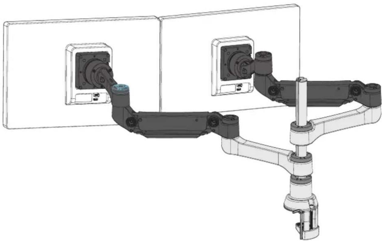
Do you work with two monitors? We recommend to place the most frequently used screen right in front of you. The other (additional) screen should be placed directly next to it, at the same height, and pulled slightly towards you. This set-up ensures that you will sit straight most of your working day.
R-Go Caparo 4 D2 Single Monitor Arm
text_image
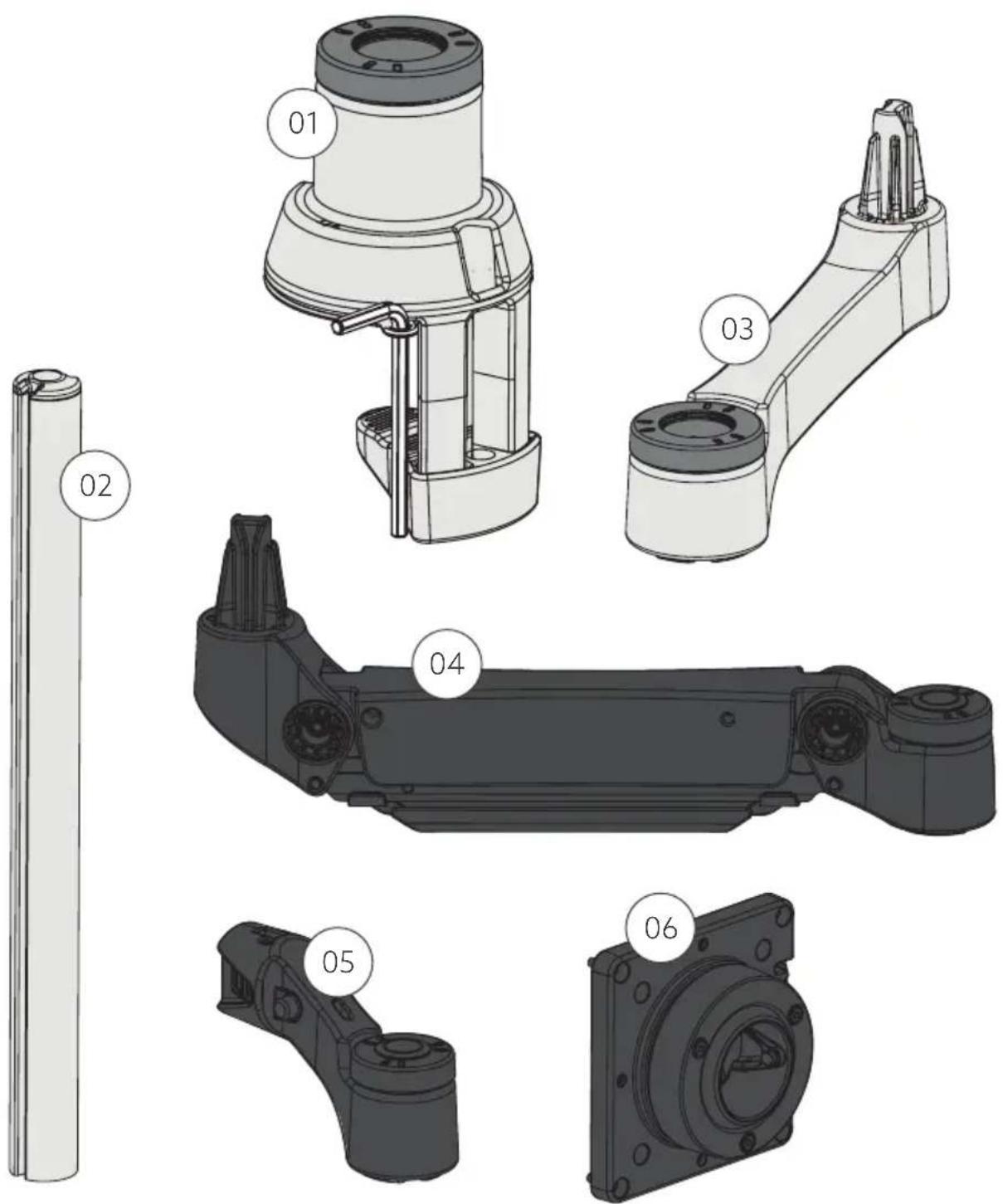
Technical diagram showing six labeled mechanical components (01–06) with corresponding 3D model views.R-Go Zepher 4 C2 Single Monitor Arm
text_image
Technical diagram showing six labeled mechanical components (01–06) with numbered callouts for identification.R-Go Caparo 4 D2 Dual Monitor Arm

text_image
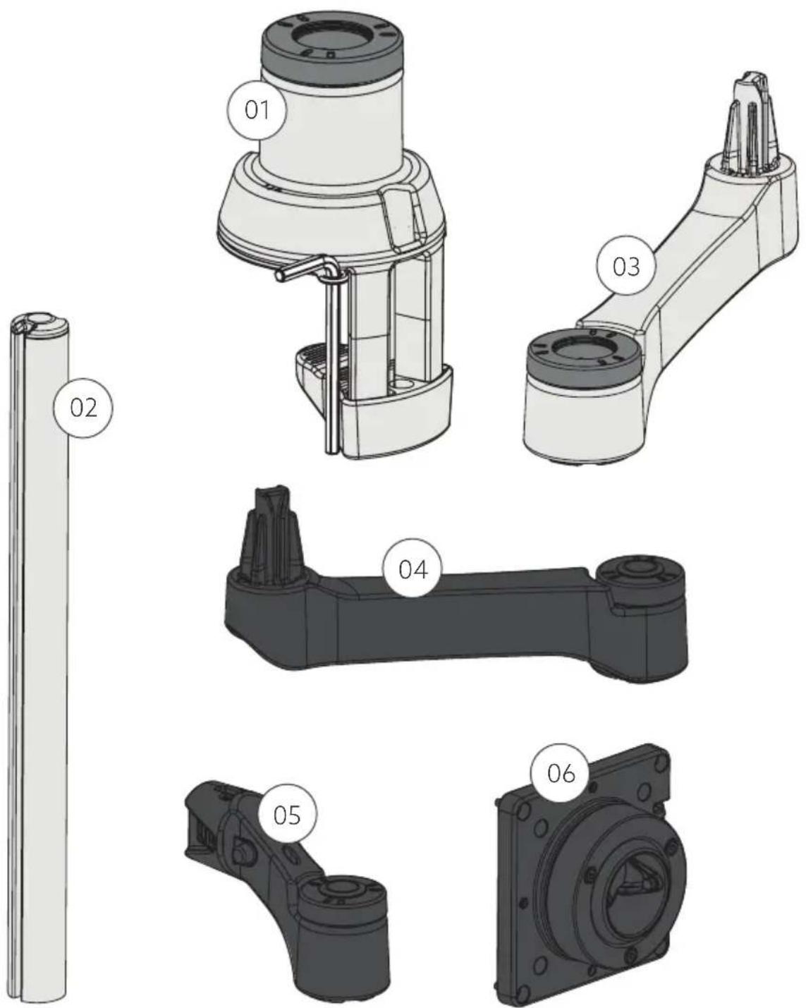
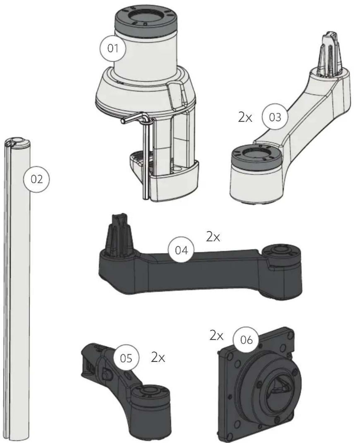
01 02 2x 03 04 2x 05 2x 2x 06R-Go Zepher 4 C2 Dual Monitor Arm
text_image
01 2x 03 02 04 2x 05 2x 2x 06Single monitor arm
Step 1 Slide the base ① onto the desktop. Tighten the screw A with the hex key B.

text_image
Technical diagram of a mechanical device with labeled components A and B, showing internal components and directional arrows.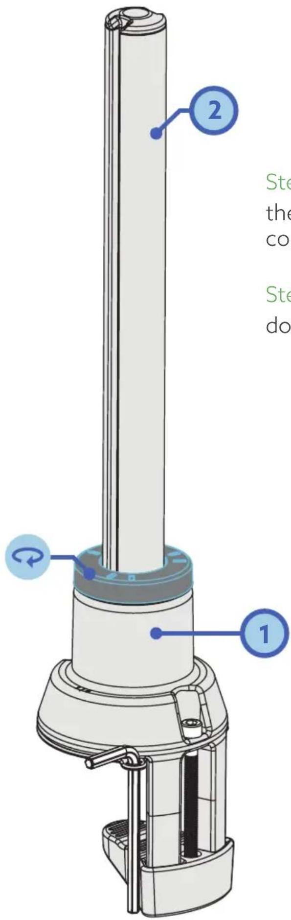
text_image
2 Ste the col Ste doStep 2a Insert the pole ② into the base ① until you hear it make contact with the table.
Step 2b Keep the pole ② pressed down while tightening the ring
Create your own setup
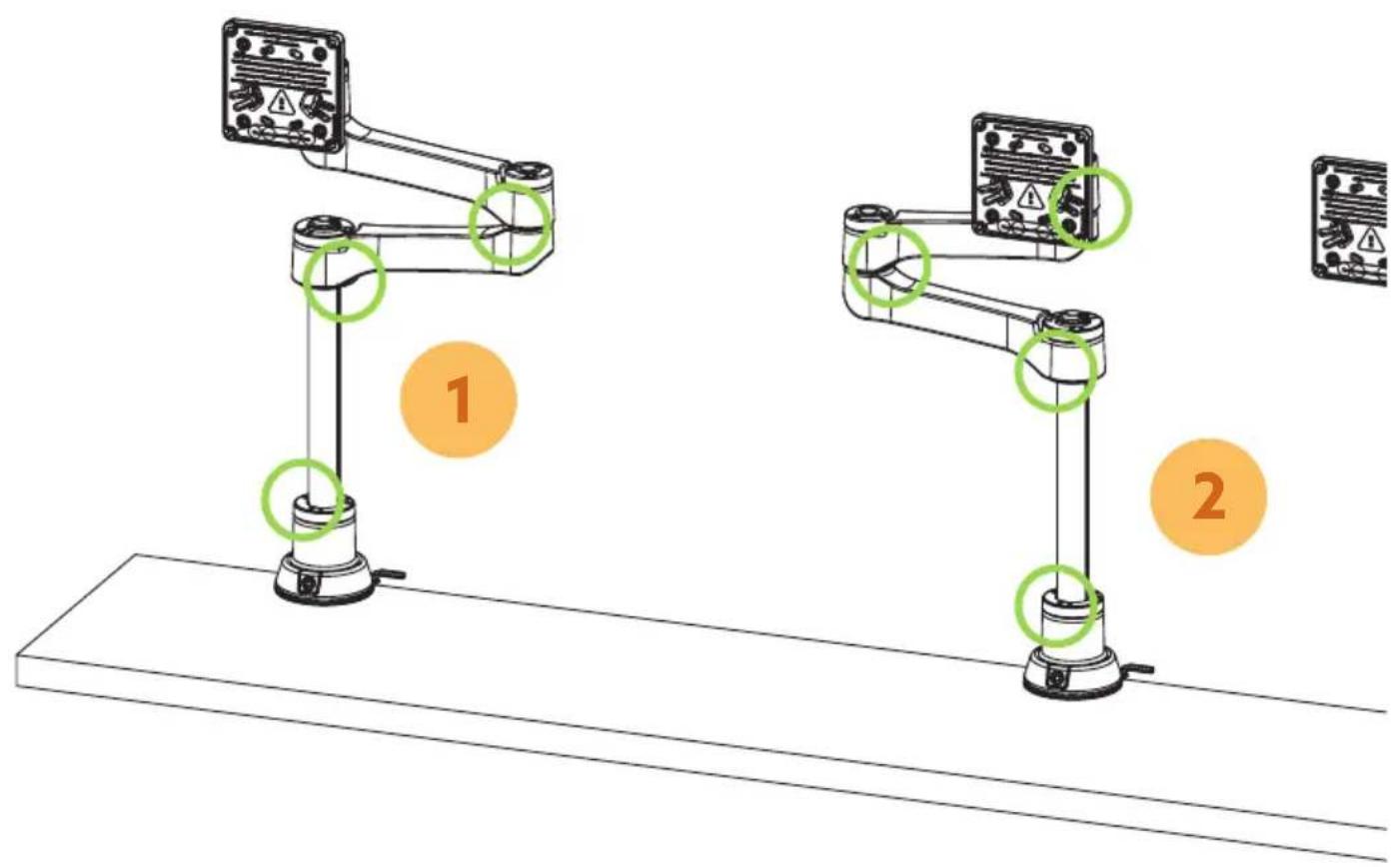
*Smart Stop™: At the bottom of the ring there is a small arrow. This arrow indicates where the Smart StopTM is, i.e. where the arm stops rotating. It is important to have the arrow on the correct side (left or right), so that the arm stops rotating and for example does not bump into an acoustic screen (see p. 10 & 11 for setup).
text_image
Diagram showing two robotic arms with labeled components and numbered annotations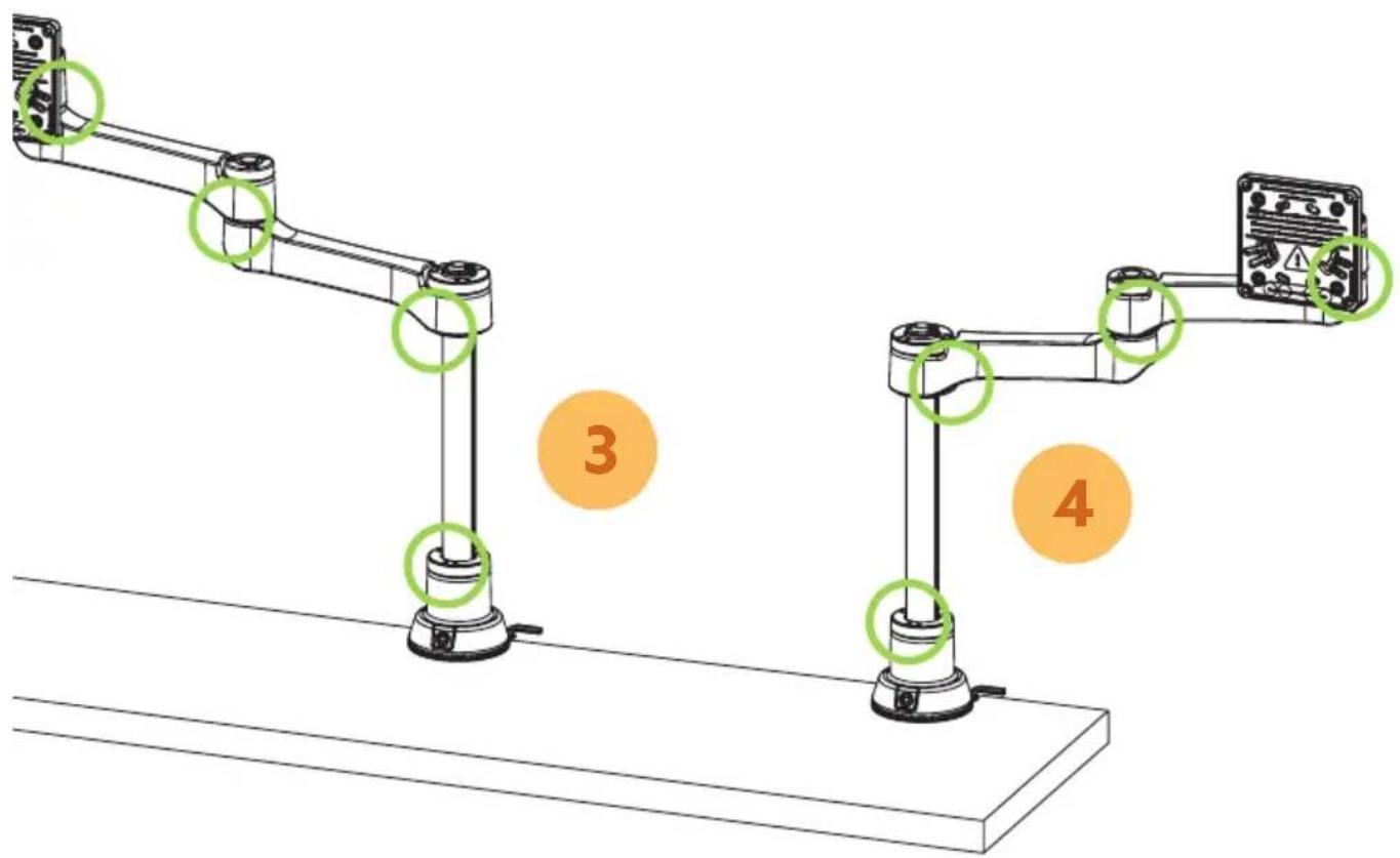
text_image
Technical diagram showing mechanical assembly with labeled components and numbered parts (3 and 4)Step 3a
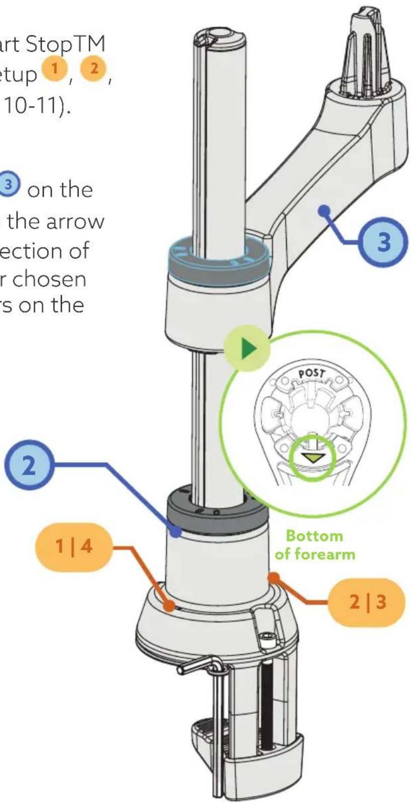
Choose which Smart StopTM setup you want (setup 1, 2, 3 or 4, see page 10-11).
Step 3b
Place the forearm ③ on the pole ②. Make sure the arrow points in the direction of the number of your chosen setup. See numbers on the base (1|4 or 2|3).
text_image
Start StopTM setup 1, 2, (10-11). ③ on the the arrow ection of or chosen s on the 3 2 1 | 4 Bottom of forearm 2 | 3
text_image
4 3 | 4 1 | 2 Bottom of upper arm Step 4a Place the upper arm the forearm ③. Wh so, make sure that ► point in the dire the number of you setup. See number base ( 1 | 2 or 3 | 4 ) . Step 4b Push the upper arm while tightening thStep 4a
Place the upper arm ④ on the forearm ③. While doing so, make sure that the arrow
point in the direction of the number of your chosen setup. See numbers on the base (1|2 or 3|4).
Step 4b
Push the upper arm ④ down while tightening the ring .

text_image
Bottom of head 5 on the upper e sure that the arrow he direction of the upper arm. 5 down while e ringStep 5a
Place the head ⑤ on the upper arm ④. Make sure that the arrow points in the direction of the arrow on the upper arm.
Step 5b
Press the head ⑤ down while tightening the ring
Step 6a
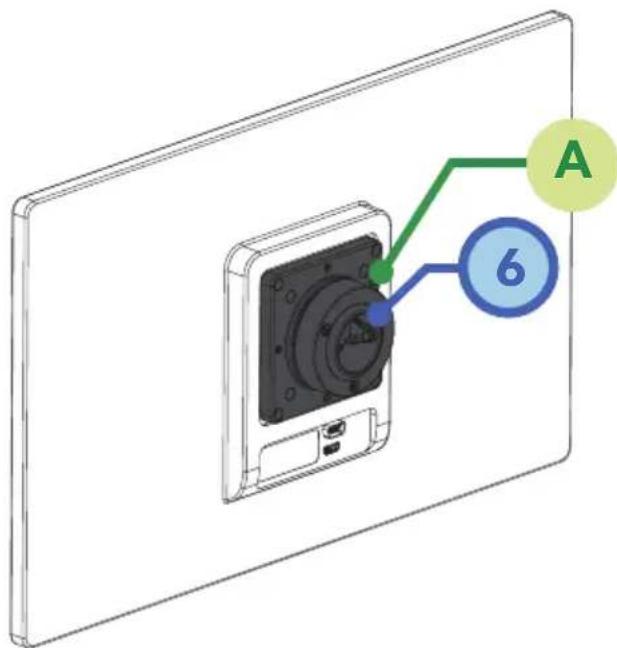
Attach the VESA plate 6 to the monitor using the enclosed hexagonal screws (see VESA plate). Use the enclosed hex key A to do this. Click the VESA plate 6 onto the head 5.
text_image
A 6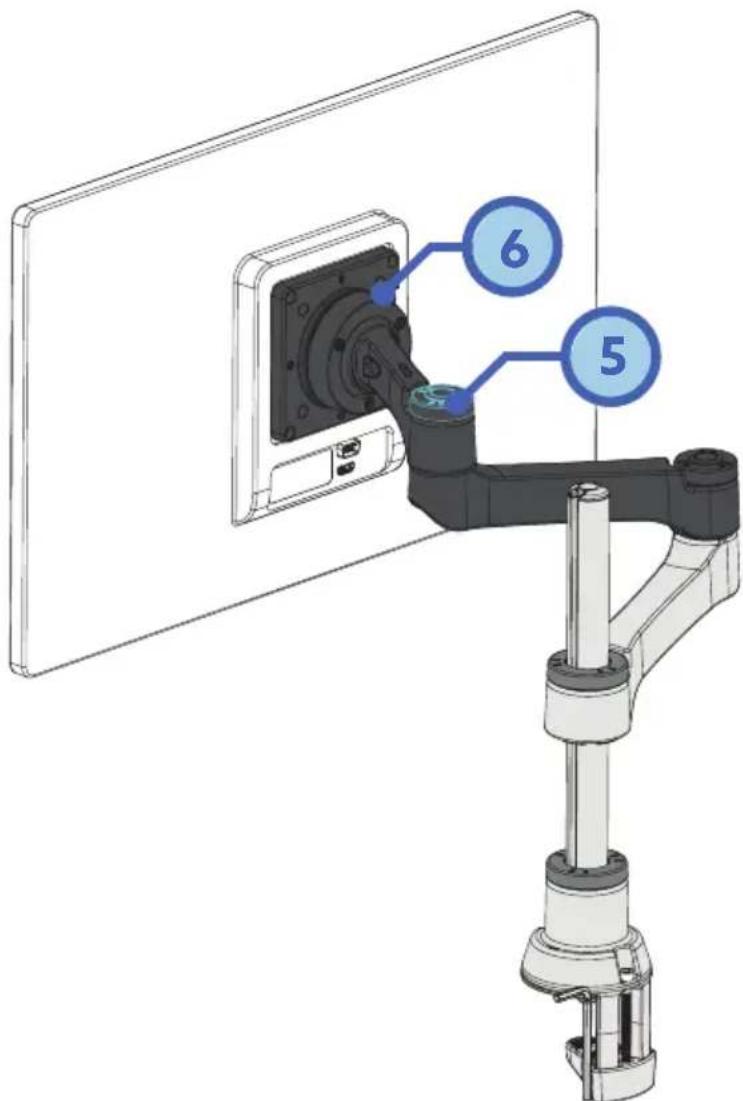
text_image
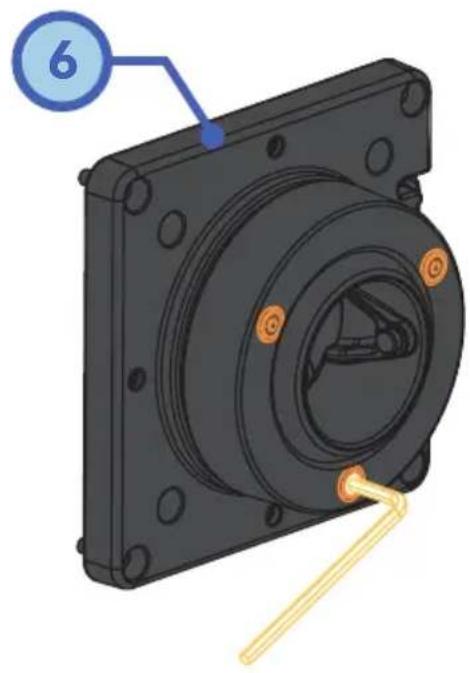
Technical diagram showing a mechanical assembly with labeled components 5 and 6, likely illustrating a robotic arm or mounting mechanism.Step 6b
In order to straighten the monitor, you will find 3 screws at the back of the VESA plate ^6 . The screws can be tightened with the enclosed hex key, so you can increase the resistance and straighten the monitor.
natural_image
3D mechanical component diagram showing a cylindrical housing with mounting holes and a yellow tool inserted (no text or symbols)Step 6c (Only for R-Go Caparo 4 D2)
Depending on the weight of your monitor, you can increase or decrease the resistance of the gas spring arm (upper arm ④) by tightening the hexagonal screws. Use the enclosed hex key.

natural_image
3D model of a mechanical component with labeled part '4' (no text or symbols beyond label)Step 6d (Only for R-Go Zepher 4 C2)
Set the arm at the correct height by sliding the lower arm on the pole. Then tighten the ring 🔒 on the lower arm.

natural_image
Technical illustration of a robotic arm assembly with a monitor mounted on a vertical post (no text or symbols visible)Dual monitor arm
Install the first arm following step 1-6 and follow step 3-6 to install the extra arm.