MGF8412GR - Freezer Atosa - Free user manual and instructions
Find the device manual for free MGF8412GR Atosa in PDF.

| Product Type | Commercial Glass Door Freezer |
| Brand | Atosa |
| Model | MGF8412GR |
| Dimensions (W x D x H) | 48.0 x 28.0 x 32.0 inches |
| Interior Capacity | 12 cu ft |
| Weight | 150 lbs |
| Power Supply | 115V / 60Hz / 1.5A |
| Temperature Range | -10°F to 0°F (-23°C to -18°C) |
| Refrigerant | R290 |
| Defrost Type | Auto Defrost |
| Cooling System | Forced Air (Fan) |
| Control Type | Digital Thermostat |
| Door Type | Hinged Glass Door |
| Number of Doors | 2 |
| Shelves | 4 Adjustable Wire Shelves |
| Interior Light | LED |
| Lock | Yes, Key Lock |
| Casters | 4 Swivel Casters |
| Warranty | 3 Years Parts and Labor |
| Certifications | ETL, NSF |
| Energy Usage | 8.0 kWh/day |
Frequently Asked Questions - MGF8412GR Atosa
User questions about MGF8412GR Atosa
0 question about this device. Answer the ones you know or ask your own.
Ask a new question about this device
Download the instructions for your Freezer in PDF format for free! Find your manual MGF8412GR - Atosa and take your electronic device back in hand. On this page are published all the documents necessary for the use of your device. MGF8412GR by Atosa.
USER MANUAL MGF8412GR Atosa
In order to provide the best service, ATOSA
requests that please register your warranty online
at www.atosausa.com
For any service issues, please kindly contact us at
Email:warranty@atosausa.com
or
Toll Free:+1-800-683-8660
Please clean the filter frequently!
Please do not overload the unit!
INSTRUCTION MANUAL
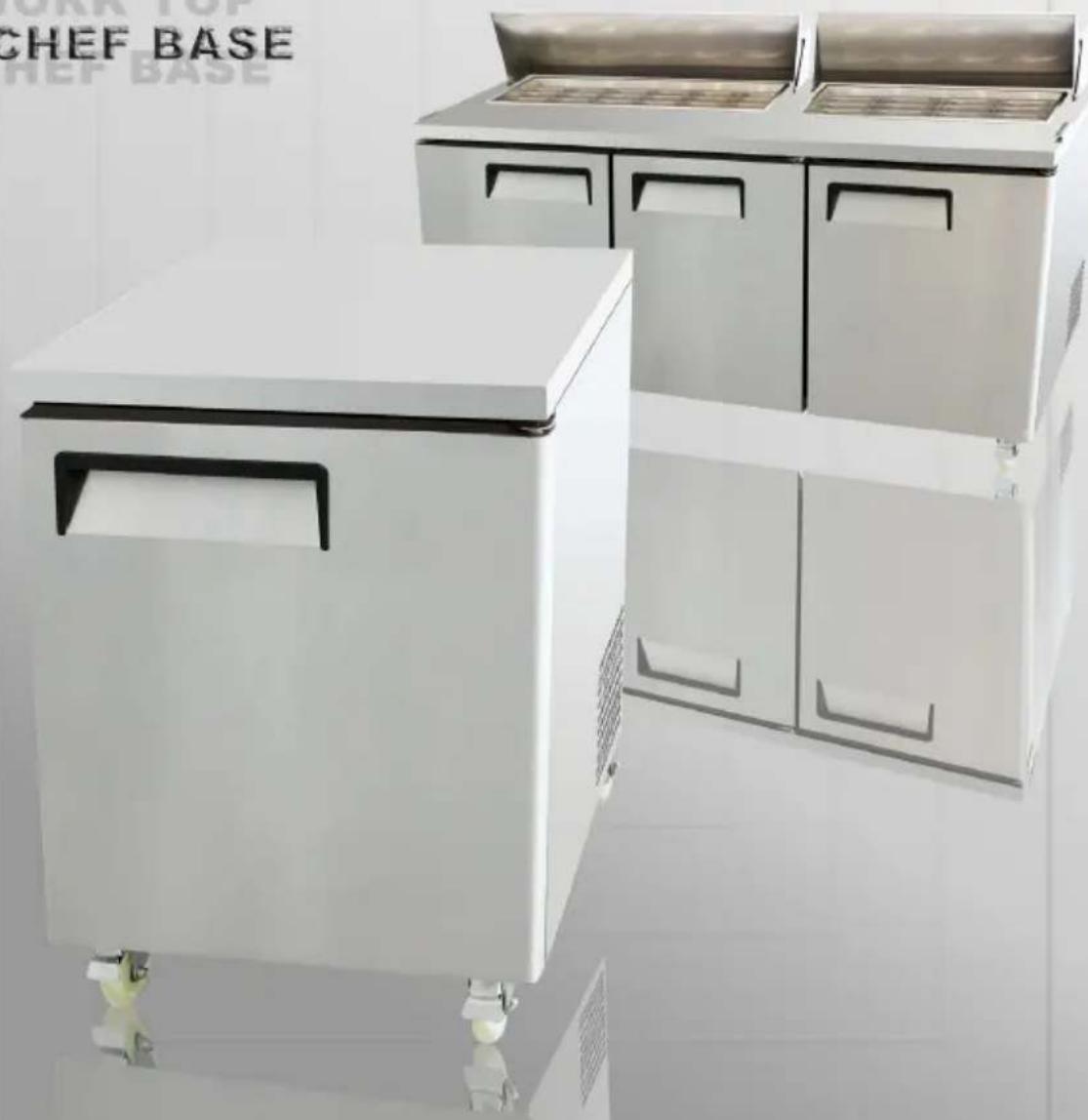
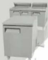
SALAD PREP TABLE
PIZZA PREP TABLE
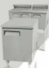
UNDERCOUNTER
WORK TOP
CHEF BASE
text_image
CHEF BASE CHEF BASEPlease read the user's manual before you use this product. If you request unnecessary services, you may waste money. Thus, fix simple troubles by yourself which you have found.
Installation, use and maintenance instructions INDEX
1 Terms and conditions....2
2 Preface....6
3 Introduction....9
4 Manufacturer's retained rights and responsibility....9
5 Transportation and storage....10
6 Commissioning....10
6.1 Positioning....10
6.2 Initial cleaning....11
6.3 Connection to electrical supply....11
6.4 Connection to drains....12
7 Technical characteristics....13
7.1 Noise and vibration....13
7.2 Possible applications....13
8 Usage....13
8.1 Activation....13
8.2 Storage of food-stuffs....13
8.3 Defrosting....14
8.3.1 Defrost timer....14
9 Maintenance....14
9.1 Periodic cleaning....14
9.2 Cleaning of condenser....14
9.3 Period of inactivity of cabinet....15
10 Trouble shooting and remedies....15
10.1 If the cabinet does not operate....15
10.2 If the required temperature is not achieved....15
10.3 If the cabinet leaks water....16
10.4 If the cabinet is unacceptably noisy....16
10.5 Improbable risks....16
11 Substitution of spares....17
12 Dismantling....17
Operating Instruction....17
Official approval and Rules.... 22
Technical Parameters.... 23
1 TERMS AND CONDITIONS:
Refrigeration
2 YEAR WARRANTY
All claims for parts or labor must be made directly through Atosa. All claims must include: model number of the unit, the serial number, proof of purchase, date of installation, and all pertinent information supporting the alleged defect. In case of compressor replacement under warranty, either compressor or compressor tag must be returned to Atosa along with above listed information. Failure to comply with warranty policies will result in voiding claims.
Two Year Parts & Labor Warranty
Atosa warrants all new refrigerated components, such as the cabinet and all parts, to be free from defects in materials or workmanship. Atosa ‘s obligation under this warranty is limited to a period of two (2) years from the date of original installation or 27 months after shipment date from Atosa, whichever occurs first. All parts covered under this warranty that are defective within two (2) years of original installation or twenty seven (27) months after shipment date from manufacturer, whichever occurs first, are limited to repair or replacement (including labor charges, of defective parts or assemblies). The labor warranty shall include standard straight time labor charges only and reasonable travel time, as determined by Atosa.
Additional Three Year Compressor Warranty
In addition to the two (2) year warranty stated above, Atosa warrants its sealed compressor to be free from defects in both material and workman ship under normal and proper use and maintenance service for a period of three (3) additional years from the date of original installation, but not to exceed five (5) years. Compressors that have been determined to be defective from Atosa within this extended period will be either repaired or replaced with a compressor or compressor parts of similar design and capacity according to Atosa ‘s discretion. The three (3) year extended compressor warranty applies only to sealed parts of the compressor and does not apply to any other parts or components. This includes, the cabinet, paint finish, temperature control, refrigerant, metering device, motor starting equipment, fan assembly, and other electrical components, etc.
R290 Compressor Warranty
The five-year compressor warranty detailed above will be void if the following procedure is not carefully adhered to:
- This system contains R290 refrigerant and lubricant. The lubricant has rapid moisture absorbing qualities.
- Drier replacement is very important and must be changed when a system is opened for servicing.
- Micron level vacuums must be achieved to insure low moisture levels in the system.
- Compressor must be obtained through Atosa, unless otherwise specified in writing, through Atosa's warranty department.
What is Not Covered by This Warranty
Atosa ‘s sole obligation under this warranty is limited to either repair or replacement of parts, subject to the additional limitationsbelow. This warranty neither assumes nor authorizes any person to assume obligations other than those expressly covered by thiswarranty.
NO CONSEQUENTIAL DAMAGES: ATOSA IS NOT RESPONSIBLE FOR ECONOMIC LOSS; PROFIT LOSS; OR SPECIAL,INDIRECT, OR CONSEQUENTIAL DAMAGES, INCLUDING WITHOUT LIMITATION, LOSSES, OR DAMAGES ARISING FROMFOOD OR PRODUCT SPOILAGE, REGARDLESS OF WHETHER OR NOT THEY RESULT FROM REFRIGERATION FAILURE.
WARRANTY IS NOT TRANSFERABLE: This warranty is not assignable and applies only in favor of the original purchaser/user to whom delivered. ANY SUCH ASSIGNMENT OR TRANSFER SHALL VOID THE WARRANTIES HEREIN AND SHALL VOID ALL WARRANTIES, EXPRESS OR IMPLIED, INCLUDING ANY WARRANTY OF MERCHANTABILITY OR LABOR COVERAGE FORCOMPONENT FAILURE OR OTHER THE WARRANTY PACKET PROVIDED WITH THE UNIT.
ALTERATION, NEGLECT, ABUSE, MISUSE, ACCIDENT, DAMAGE DURING TRANSIT OR INSTALLATION, FIRE, FOOD, OR ACTSOF
GOD: Atosa is not responsible for the repair or replacement of any parts that are determined to have been subjected after the date of manufacture to alteration, neglect, abuse, misuse, accident, damage during transit or installation, fire, flood, or act of God.
IMPROPER ELECTRICAL CONNECTIONS: Atosa IS NOT RESPONSIBLE FOR THE REPAIR OR REPLACEMENT OF FAILED OR DAMAGED COMPONENTS RESULTING FROM ELECTRICAL POWER FAILURE, THE USE OF EXTENSION CORDS, LOW VOLTAGE, OR VOLTAGE DROPS TO THE UNIT. THE TWO (2) YEAR PARTS & LABOR WARRANTY AND THE ADDITIONAL THREE (3) YEAR COM-PRESSOR WARRANTY ARE AS DESCRIBED ABOVE. THESE WARRANTIES ARE EXCLUSIVE AND IN LIEU OF ALL OTHER WARRANTIES, INCLUDING IMPLIED WARRANTY AND MERCHANTABILITY OR FITNESS FOR A PARTICULAR PURPOSE. THERE ARE NO WARRANTIES WHICH EXTEND BEYOND THE DESCRIPTION ON THE FACE HEREOF.
Outside U.S. and Canada: This warranty does not apply to areas outside the continent of the United States. Atosa is not responsible for any warranty claims made on products sold or used in such areas.*In some cases, a 25% restocking fee may be charged to a buyer for returned items.*Atosa may at any time modify our equipment in order to provide and insure a superior product. Change is sometimes necessary to keep up with today's high standards in our industry. Atosa reserves the final interpretation of all public materials.
2. Preface
Please read instructions before using this appliance.
IMPORTANT SAFETY INSTRUCTION
▲ To reduce the risk of fire, electric shock, or injury to persons when using your product, basic safety precautions should be followed, including the following.
▲ This appliance must be properly installed and located in accordance with the Installation Instruction before it is used.
▲ Before the appliance is plugged in, ensure that the rated voltage corresponds to the voltage of the electrical system in your home. The power plug should have its own independent socket. Using adapters may cause overheating or burning.
▲ This appliance can be used by children aged from 8 years and above and persons with reduced physical, sensory or mental capabilities or lack of experience and knowledge if they have been given supervision or instruction concerning use of the appliance in a safe way and understand the hazards involved.
▲ Children shall not play with the appliance.
▲ Cleaning and user maintenance shall not be made by children without supervision.
▲ If the supply cord is damaged, it must be replaced by the manufacturer or its service agent or a similarly qualified person in order to avoid a hazard.
▲ Connect to properly grounded outlets only. Avoid the use of extension cords. Do not run cord under carpeting, runners or the like. Arrange cord away from traffic area and where it will not create a tripping hazard.
▲ Always unplug appliance when not in use and before cleaning, adjusting or maintaining this machine. To disconnect appliance, turn switch off and remove plug from power source.
▲ Do not disconnect by pulling on the cord. Always disconnect by grasping and pulling on the plug top.
▲ Do not pull out the cord or touch the power plug with wet hands. Clean water or dust from the power plug and insert it with the ends of the pins securely connected.
▲ Do not use outdoors.
▲ Do not splash water on the appliance. It may cause a malfunction or electric shock.
▲ Do not disassemble, repair or alter the appliance. It may cause fire or abnormal operations, which may lead to injury.
▲ After your fridge-freezer is in operation, do not touch the cold surfaces in the freezer compartment, particularly when hands are damp or wet. Skin may adhere to these extremely cold surfaces.
▲ Never place glass products in the freezer because they may be broken when their inner contents are frozen.
▲ The refrigerant and insulation blowing gas used in the appliance require special disposal procedures. When disposal, please consult with service agent or a similarly qualified person.
▲ Do not store explosive substances such as aerosol cans with a flammable propellant in this appliance.
▲ WARNING: Keep clear of obstruction all ventilation openings in the appliance enclosure or in the structure for building-in.
▲ WARNING: Do not use mechanical devices or other means to accelerate the defrosting process, other than those recommended by the manufacturer.
▲ WARNING: Do not damage the refrigerant circuit.
▲ WARNING: Do not use electrical appliances inside the food storage compartments of the appliance, unless they are of the type recommended by the manufacturer.

text_image
Warning sign depicting a flame symbol inside a triangle, indicating hazardous material hazard.Warning: Risk of fire / flammable materials
CAUTION: RISK OF FIRE AND EXPLOSION WITH FLAMMABLE REFRIGERANT R290.
▲ If you need the electronic version instruction manual, please ask the manufacturer or its service agent.
▲ Max. Load of shelf is 40 kg.
This instruction manual provides all the necessary information regarding:
▲ use of the refrigerator
▲ technical specifications
▲ installation and handling
▲ operator procedures and instructions
▲ maintenance operation
The manual is to be considered an integral part of the refrigerator and should be stored in a safe place for father consult to permit a good working life of the refrigerator.
The appliance is intended for commercial use only.
■ Component parts shall be replaced with like components and that servicing shall be done by factory authorized service personnel.
3 INTRODUCTION
This equipment has been produced be internally or externally in its aesthetics and componability. In response to the specific exigencies of our clientele; furthermore it has been mechanically and aesthetically checked in every aspect before despatch. For the correct utilisation of the equipment; carefully read the instructions, observe all the recommendations contained therein, consign this manual which constitutes an integral part of the essence of the equipment to the end user who is requested to retain it for future consultation. By observing these recommendations, you will guarantee the extended trouble-free operation of the equipment.
4 MANUFACTURER'S RETAINED RIGHTS AND RESPONSIBILITY
It is forbidden to reproduce, partially or totally, these instructions without the express authorisation of the manufacturers.
The manufacturers deny all responsibility to third parties in consequence of:
- Non observance of the warnings and instruction contained in the test;
- Non observance of the parameters of utilisation of the equipment;
- Unreasonable or wrongful utilisation by un-trained personnel;
- use non conforming to local statutes;
- Unauthorized modifications and/or repairs undertaken by non trained or authorized personnel.
- Utilisation of non original spares or accessories;
- Exceptional occurrences;
- Imprecise instructions contained for whatever reason in the current manual;
The manufacturers reserve the right to introduce any modification deemed necessary without warning.
5 TRANSPORTATION AND STORAGE
The equipment is wrapped in absorbent material and contained and fixed within a wooden platform and paper box.
Whist awaiting by definitive collection, these should be stored within a protected and covered environment at a temperature between -25^ / +55^ , with ambient humidity between 30 / 95% . Do not stack more than four items.
6 COMMISSIONING
Carefully read the label on the equipment, do not cover for any reason whatsoever. and replace them immediately if damaged. Do not remove protection or panelling that require the usage of tools.
6.1 POSITIONING
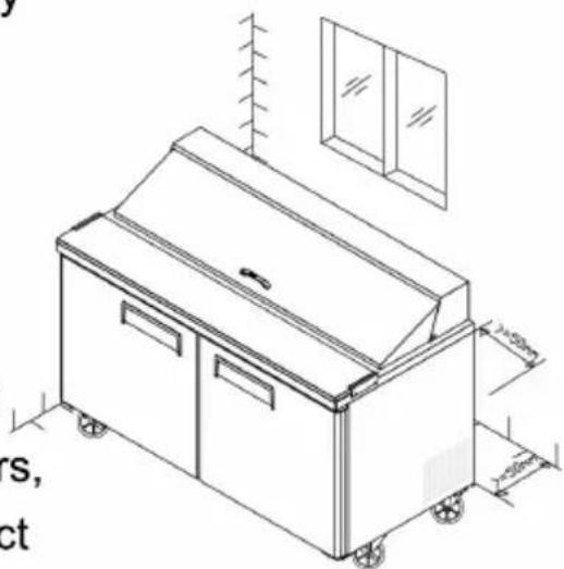
Ensure that in respect of the dimensions, the space reserved for the equipment permits its correct utilisation and ease of maintenance. After carefully unpacking the display case, remove the white PVC protective film and all of the manufacturer's material which safeguards the item in transit. Place the cabinet on a flat surface and level it by screwing and adjusting the leveling legs to ensure its efficient operation. The cabinet must be lifted only from the exterior of the base to avoid the possibility of damage. Do not move the cabinet by application of pressure to the surface.
if the device has been positioned horizontally (integral condensing unit). wait two hours before activating it. Packing and protective film should be disposed off as indicated by the local authorities. The equipment must not be installed within explosive ambience, In the open air or exposed to rain the correct siting is; distant from direct sources (radiators direct lighting, etc...) and protected from direct sunlight and draughts. Air circulation must be freely maintained around the condensing unit, be it integral or remote.
In observance of these specific conditions will detrimentally affect the cabinet.
natural_image
Isometric line drawing of a kitchen appliance with wheels and a cabinet, no text or symbols present6.2 INITIAL CLEANING
Before use all parts of the cabinet should be cleaned, For the walls and all the internal parts use an antibacterial detergent. For the plastic parts use a moistened cloth. Dry with a soft clean cloth. use little or no water.
Do not use harsh or abrasive solvents or detergents

natural_image
Illustration of a kitchen scene with a smiling refrigerator, a person washing dishes, and a food item (no text or symbols)During cleaning do not approach bare-handed those parts which could cut (evaporator, condenser, etc.) and always use protective gloves.
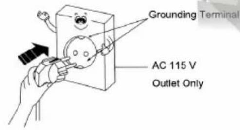
6.3 Electrical connection
Check that the supply conforms to the requirements listed on the factory label and that it is provided with a fall-safe protection or automatic circuit
breaker with an efficient earth connection. Should there not be an electrical safety feature have this introduced by a qualified person. by means of a omnipolar switch as indicated in the safety regulations with a means of a omnipolar switch as indicated in the safety regulations with a minimum clearance of the contacts of 3 mm. where the cabinet has to be installed at some distance from the electrical source. ensure that the conforms to the local regulations. Cabinet supplied with integral condensing units are provided with an appropriate plug fitted with a neutral and earth; the supply cable must be well stretched (avoid coiling and superimposition). it must
not be exposed to the possibility of damage by third parties. it should not be in contact with liquids, water or heat sources. in the event of damage it must be replaced by qualified personnel. Always avoid the use of reducers or adapters.
text_image
Grounding Terminal AC 115 V Outlet Only
text_image
A Ground wire Cu Over 75 cm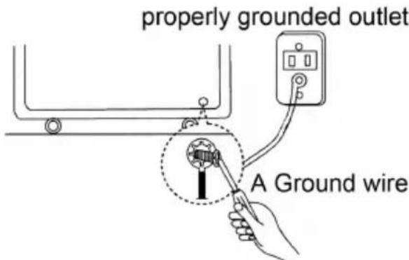
text_image
properly grounded outlet A Ground wire
a gas pipe
water pipe

telephone wire
6.4 CONNECTION TO DRAINS
The dispersal of defrost water is automatic in all models with integral condensing unit.
7 TECHNICAL CHARACTERISTICS
7.1 NOISE AND VIBRATION
The sound level of the equipment fitted with integral hermetic condensing unit does not exceed 70 dB, it is therefore not necessary to provide sound insulation. Under normal conditions the equipment does not generate vibrations which affect surroundings.
7.2 POSSIBLE USAGES
Do not utilise the equipment to store medical supplies. the optimum operational ambient temperatures are between +10°C / +40°C.
The possible application are: display salads, keep cooling; preparation, and sale of salads, fruits, Vegetables and cold dishes
8 USAGE
8.1 ACTION
Power connection and adjust the thermostat.
8.2 STORAGE OF FOOD-STUFFS
In order to obtain the best functioning of the case it is necessary to observe the following instruction:
- Place the merchandise into the unit only after it has reached the desired operating temperature given on the digital display.
- Do not place uncovered hot foods or liquids inside the unit
- Package or protect foods when possible
- Do not limit the circulation of air inside the call with superfluous obstacles.
- Avoid frequent or prolonged openings of the door/drawers
- Wait a few moments before reopening the door/drawer just after it has been closed.
Whilst stocking only open and fill a drawer at a time to eliminate the risk of over-balancing or ask to the supplier the fixable feet.
8.3 DEFROSTING
8.3.1 DEFROST TIMER
The defrost timer automatically 4 times in 24 hours, its timer will reset to the time of the initial first start-up.
9 MAINTENANCE
9.1 PERIODIC CLEANING
For hygienic reasons and improved performance clean at least once a week the internal basin. Make sure switch off the power supply before cleaning..
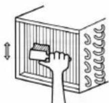
9.2 CLEANING OF CONDENSER
natural_image
Illustration of a hand cleaning a wall-mounted device with a brush (no text or symbols)For improved performance clean the condenser at least once a month.
Before beginning turn off the equipment, and disconnect the plug. Close and protect the unit.
- Unscrew, rotate and remove protective grill
- Remove the dust deposited on the front surface of the condenser using a brush and a vacuum cleaner and restore previous conditions.
9.3 PERIOD OF INACTIVITY OF CABINET
During periods of inactivity, remove the products from the cabinet and then follow these directions:
- Remove the plug out from the outlet and carefully clean the unit as per periodic cleaning
- Cover the cabinet whit a cloth that allows air circulation in the interior.

natural_image
Cartoon illustration of a smiling refrigerator with two hands and legs, no text or symbols present10 TROUBLE SHOOTING AND REMEDIES
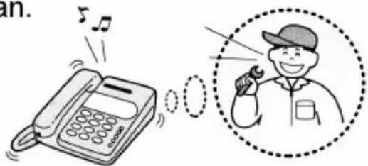
Often, the malfunction of a unit is due to simple causes which can easily be eliminated without contacting a technician.
Therefore execute the following controls
text_image
an.10.1 If the cabinet does not operate, make sure that:
- The plug has been correctly inserted into the socket.
- The supply cord is not damaged.
10.2 If the required temperature is not achieved, make sure that;
- The command switch is turned on.
-
The thermostat range is correctly regulated.
-
The cabinet is neither in the defrosting phase nor in the post-defrosting pase.
- The evaporator is not covered with frost.
- The condenser is not blocked with dust.
- The cabinet is not located near heat sources or its condensing unit has uninterrupted air flow.
- The stored foods or other objects do not inhibit proper closing of the unit.
- The cabinet is not working in anomalous conditions (overloaded, loaded with hot food, or loaded in a way that prevents proper air circulation).
10.3 If the cabinet leaks water, make that:
- The collecting container or the device for condensing water elimination are not damaged.
- The discharge outlets are not blocked or obstructed.
- The cabinet has been properly leveled.
10.4 If the cabinet is unacceptably noisy, make sure that:
- The frame does not have loose screws or bolts.
- The cabinet has been laid in a stable position and correctly leveled.
If, after all these controls, the malfunctioning continues, it is advisable to contact technical assistance. Be prepared to supply the following information:
- The model trade name and the serial number (both can be found on the technical data plate).
10.5 IMPROBABLE RISKS
In case of fire unplug the cabinet, if possible, and use a powder fire extinguisher.
11 SUBSTITUTION OF SPARES
Before commencing any service or maintenance work, isolate the cabinet from the electrical supply.
Always fit original spares which may be obtained from an authorized concessionaire or stockist.
12 DISMANTLING
The scrapping of the cabinet requires to be undertaken by specialized company, licensed by the local authorities, and observing local statutes. Polyurethane foaming material, not fire-resistant, when deal with the material, should be according with local law and statute.
- The cabinet consists of:
- Structure in steel plate,
- Electrical components and cables,
- Electrical compressor.
- Plastic materials,
- Refrigerant fluid which must not be discharged into the atmosphere.

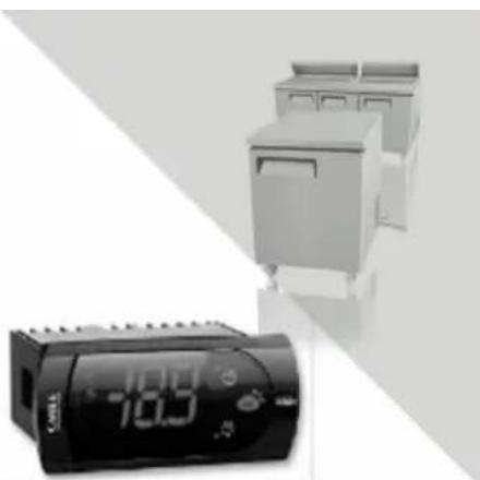
text_image
Operating Instruction
natural_image
Electronic device with a 185 timer and multiple rectangular modules (no visible text or symbols)-
New upright air-cooling refrigerator should be opened and ventilate it before it is in use.
-
After connecting the power supply, press the
"POWER" switch on the controller keyboard (Green Indicator Light ON), the fridge will come to work. The microcomputer controller, installed in the controller keyboard, could automatically adjust the temperature ranges. This intelligent digital controller works as: if the temperature increases and reaches set point plus differential the compressor is started and then turned off when the temperature reaches the set point value again.
- Microcomputer Controller Operation Instruction:
Display and functions:
natural_image
Exterior view of a kitchen appliance with digital display (no visible text or symbols)During normal operation, the controller displays the value of the probe set using parameter/4(=1 ambient probe, default, =2 second probe, =3 third probe). In addition, the display has LEDs that indicate the activation of the control functions (see Table 1), while the 3 buttons can be used to activate/deactivate some of the functions (see table 2).
LEDs and associated functions Tab.1
| icon | function | normal operation | start up | ||
| ON | OFF | blink | |||
 | Compressor | on | off | request | ON |
 | fan | on | off | request | ON |
 | defrost | on | off | request | ON |
 | aux | output on | output off | - | ON |
 | alarm | all | no alarm | - | ON |
 | clock | RTC fitted and enabled,at least 1 time band set | RTC not fitted or disabled,not even 1 time band set | - | ON if RTC fitted |
Table of functions activated by the buttons Tab.2
| button | normal operation | start up | ||||
| pressing the button alone | pressed together | |||||
 | upON/OFF | more than 3s toggleON/OFF | pressedtogether start/stop continuouscycle | - | ||
 | downdefrost | more than 3s:start/stop defrost | Pressedtogetherstartparameterresetprocedure | for 1s displayfirmware vers.code | ||
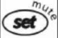 | setmute | -1s: display/set the set point-more than 3s: access parametersetting menu(enter password 22)-mute audible alarm (buzzer) | - | for 1s RESETcurrent EZYset | ||
Setting the set point(desired temperature)
- press SET for 1s the set value will start flashing after a few moments;
- increase or decrease the value using UP or DOWN;
- press SET to confirm the new value.
Switching the device ON/OFF
Press UP for more than 3s. the control and defrost algorithms are now disabled and the instrument displays the message "OFF" alternating with the temperature read by the set probe.
Manual defrost
Press for DOWN more than 3s (the defrost starts only the temperature conditions are valid).
Continuous cycle
Press UP and DOWN together for more than 3s.
Table of alarms
| Alam code | buzzer and alarm relay | LED | Description | Parametri coninvolti |
| E0 | active | ON | probe 1 error=control | - |
| E1 | inactive | ON | probe 2 error=defrost | [d0=0/1] |
| E2 | inactive | ON | probe 3 error=condenser | [A4=10] |
| IA | active | ON | external alarm | [A4=10][+A7] |
| dOr | active | ON | open door alarm | [A4=7/8][+A7] |
| LO | active | ON | low temperature alarm | [AL][Ad] |
| HI | active | ON | high temperature alarm | [Ah][Ad] |
| EE | inactive | ON | unit parameter error | - |
| EF | inactive | ON | operating parameter error | - |
| Ed | inactive | ON | defrost ended by timeout | [dP][dt][d4][A8] |
| dF | inactive | ON | defrost running | [d6=0] |
| cht | inactive | ON | condenser dirty pre-alarm | [A4=10] |
| CHT | active | ON | condenser dirty alarm | [A4=10] |
| EtC | inactive | ON | clock alarm |
Dixell XR02CX XR03CX XR06CX
-
Microcomputer panel sketch map, meanings of running indicator light and LED showing.
-
SET To display target set point, in programming mode it selects a parameter or confirm an operation.
text_image
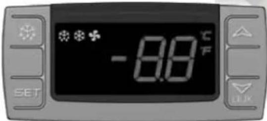
-8.8°C F SET(Mod. XR06CX)
To start a manual defrost.
In programming mode it browses the parameter codes or increases the displayed value.
AUX In programming mode it browses the parameter codes or decreases the displayed value.
+ To lock or unlock the keyboard SET+ To enter in programming mode SET+ To return to room temperature display.
| LED | MODE | SIGNIFICATO |
| On | Compressor enabled | |
| Flashing | Anti short cycle delay enabled (AC parameter) | |
| On | Defrost in progress | |
| Flashing | Dripping in progress | |
| On | Fans output enabled | |
| Flashing | Fans delay after defrost | |
| On | Measurement unit | |
| Flashing | Programming mode | |
| On | Measurement unit | |
| Flashing | Programming mode |
- How to see the point .
Push and immediately release the SET key, the set point will be showed; Push and immediately release the SET key or wait about 5s to return to normal visualisation.
- How to change the setpoint.
Push the SET key for more than 2 seconds to change the Set point value; The value of the set point will be displayed and the “°C” or “°F” LED starts blinking;
To change the Set value push the △ or ▽ AUX arrows.
To memorise the new set point value push the SET key again or wait 10s.
- How to start a manual defrost.
Push the DEF ✿ key for more than 2 seconds and a manual defrost will start.
- How to change a parameter value
To change the parameter's value operate as follows:
Enter the Programming mode by pressing the SET+▼ keys for 3s ("°C" or "°F" LED starts blinking).
Select the required parameter. Press the "SET" key to display its value Use △ or ▽ _AUX to change its value.
Press "SET" to store the new value and move to the following parameter.
To exit: Press SET+△ or wait 15s without pressing a key.
NOTE: the set value is stored even when the procedure is exited by waiting the time-out to expire.
- To lock the keyboard.
Keep pressed for more than 3s the ▽+△ keys.
The "OF" message will be displayed and the keyboard will be locked. If a key is pressed more than 3s the "OF" message will be displayed.
- To unlock the keyboard.
Keep pressed together for more than 3s the ▽+△ keys till the “on” message will be displayed.
- Alarm signalling.
| Mess. | Cause | Outputs |
| "P1" | Room probe failure | Compressor output according to “Cy” e “Cn” |
| "P2" | Evaporator probe failure | Defrost end is timed |
| "HA" | Maximum temperature alarm | Outputs unchanged |
| "LA" | Minimum temperature alarm | Outputs unchanged |
| “EA” | External alarm | Outputs unchanged |
| “CA” | Serious external alarm | All outputs OFF |
| “dA” | Door Open | Compressor and fans restarts |
OFFICIAL APPROVAL AND RULES
CONFORMS TO UL STD.471
CERTIFIED TO CSA STD.C22.2 NO.120
CONFORMS TO NSF/ANSI STD. 7

text_image
C LISTED US ETV CMIntertek
4003935
CONFORMS TO UL STD.471
CERTIFIED TO CSA STD.C22.2 NO.120

text_image
ETV CM SANITATION LISTEDIntertek
4003935
CONFORMS TO NSF/ANSI STD.7
Technical Parameters
| Product | Model code | Power source (V) | Rating frequency(Hz) | Input power (w) | Rated current(A) | Temperature range (°C) | Refrigerant | Amount(oz) | Dimension (mm) | Volume (cu.ft) |
| Undercounter | MGF8401GR | 115 | 60 | 260 | 2.3 | +1~+8 | R290 | 2.5 | 698×762×929 | 7.15 |
| MGF8402GR | 115 | 60 | 260 | 2.3 | +1~+8 | R290 | 3.9 | 1225×762×929 | 13.38 | |
| MGF8403GR | 115 | 60 | 320 | 2.8 | +1~+8 | R290 | 4.2 | 1530×762×929 | 17.2 | |
| MGF8404GR | 115 | 60 | 320 | 2.8 | +1~+8 | R290 | 4.2 | 1846×762×929 | 21.13 | |
| MGF8405GR | 115 | 60 | 200 | 1.8 | -22~-17 | R290 | 3.5 | 698×762×929 | 7.15 | |
| MGF8406GR | 115 | 60 | 300 | 2.6 | -22~-17 | R290 | 4.6 | 1225×762×929 | 13.38 | |
| MGF8407GR | 115 | 60 | 300 | 2.6 | -22~-17 | R290 | 4.6 | 1530×762×929 | 17.2 | |
| MGF36RGR | 115 | 60 | 260 | 2.3 | +1~+8 | R290 | 3.5 | 923×762×929 | 8.68 | |
| MGF36FGR | 115 | 60 | 300 | 2.6 | -22~-17 | R290 | 3.9 | 923×762×929 | 8.68 | |
| Work Top Refrigerator | MGF8408GR | 115 | 60 | 260 | 2.3 | +1~+8 | R290 | 2.5 | 698×762×1035 | 7.15 |
| MGF8409GR | 115 | 60 | 260 | 2.3 | +1~+8 | R290 | 3.9 | 1225×762×1035 | 13.38 | |
| MGF8410GR | 115 | 60 | 320 | 2.8 | +1~+8 | R290 | 4.2 | 1530×762×1035 | 17.2 | |
| MGF8411GR | 115 | 60 | 320 | 2.8 | +1~+8 | R290 | 4.2 | 1846×762×1035 | 21.13 | |
| MGF8412GR | 115 | 60 | 200 | 1.8 | -22~-17 | R290 | 3.5 | 698×762×1035 | 7.15 | |
| MGF8413GR | 115 | 60 | 300 | 2.6 | -22~-17 | R290 | 4.6 | 1225×762×1035 | 13.38 | |
| MGF8414GR | 115 | 60 | 300 | 2.6 | -22~-17 | R290 | 4.6 | 1530×762×1035 | 17.2 | |
| MGF36RWGR | 115 | 60 | 260 | 2.3 | +1~+8 | R290 | 3.5 | 923×762×929 | 8.68 | |
| MGF36FWGR | 115 | 60 | 300 | 2.6 | -22~-17 | R290 | 3.9 | 923×762×929 | 8.68 | |
| Chef Base | MGF8448GR | 115 | 60 | 260 | 2.3 +1~+8 | R290 | 3.9 | 904×815×520 | 4.7 | |
| MGF8449GR | 115 | 60 | 260 | 2.3 +1~+8 | R290 | 3.9 | 1056×815×520 | 4.7 | ||
| MGF8450GR | 115 | 60 | 260 | 2.3 | +1~+8 | R290 | 4.6 | 1230×815×520 | 7.7 | |
| MGF8451GR | 115 | 60 | 260 | 2.3 | +1~+8 | R290 | 4.6 | 1318×815×520 | 8.4 | |
| MGF8452GR | 115 | 60 | 260 | 2.3 | +1~+8 | R290 | 4.6 | 1536×815×520 | 8.4 | |
| MGF8453GR | 115 | 60 | 260 | 2.3 | +1~+8 | R290 | 4.6 | 1840×815×520 | 12.1 | |
| MGF8454GR | 115 | 60 | 260 | 2.3 | +1~+8 | R290 | 4.6 | 1930×815×520 | 12.1 | |
| Product | Model code | Power source (V) | Rating frequency(Hz) | Input power (w) | Rated current(A) | Temperature range (°C) | Refrigerant | Amount(oz) | Dimension (mm) | Volume (cu.ft) |
| Salad Prep table | MSF8301GR | 115 | 60 | 260 | 2.3 | +1~+8 | R290 | 2.8 | 698×762×1109 | 7.15 |
| MSF8302GR | 115 | 60 | 260 | 2.3 | +1~+8 | R290 | 4.2 | 1225×762×1109 | 13.38 | |
| MSF8303GR | 115 | 60 | 320 | 2.8 | +1~+8 | R290 | 4.2 | 1530×762×1109 | 17.2 | |
| MSF8304GR | 115 | 60 | 320 | 2.8 | +1~+8 | R290 | 4.6 | 1846×762×1109 | 21.13 | |
| MSF3610GR | 115 60 | 260 | 2.3 | +1~+8 | R290 | 3.5 | 923×762×1109 | 8.68 | ||
| Mega Top | MSF8305GR | 115 | 60 | 260 | 2.3 | +1~+8 | R290 | 2.8 | 1230×863×1183 | 7.15 |
| MSF8306GR | 115 | 60 | 260 | 2.3 | +1~+8 | R290 | 4.2 | 1318×863×1183 | 13.38 | |
| MSF8307GR | 115 | 60 | 320 | 2.8 | +1~+8 | R290 | 4.2 | 1536×863×1183 | 17.2 | |
| MSF8308GR | 115 | 60 | 320 | 2.8 | +1~+8 | R290 | 4.6 | 1930×863×1183 | 21.13 | |
| MSF3615GR | 115 60 | 260 | 2.3 +1~+8 | R290 3.5 | 923×863×1183 | 8.68 | ||||
| Pizza Prep Table | MPF8201GR | 115 | 60 | 260 | 2.3 | +1~+8 | R290 | 4.9 | 1117×840×1035 | 9.7 |
| MPF8202GR | 115 | 60 | 320 | 2.8 | +1~+8 | R290 | 4.9 | 1701×840×1035 | 18.5 | |
| MPF8203GR | 115 | 60 | 360 | 3.1 | +1~+8 | R290 | 4.9 | 2362×840×1035 | 28.4 | |
NOTES :If the technical data has any changes, we will not notify you any longer.
W081108202
version number 20200708