BRR108600 - Air purifier Bröhn - Free user manual and instructions
Find the device manual for free BRR108600 Bröhn in PDF.

User questions about BRR108600 Bröhn
0 question about this device. Answer the ones you know or ask your own.
Ask a new question about this device
Download the instructions for your Air purifier in PDF format for free! Find your manual BRR108600 - Bröhn and take your electronic device back in hand. On this page are published all the documents necessary for the use of your device. BRR108600 by Bröhn.
USER MANUAL BRR108600 Bröhn
Providing the best for a better future
Please read this manual carefully before using, and keep it for future
User Manual
WALL CANOPY RANGEHOOD
Model: BRR108 600; BRR108 900; BRR129 900; BRR206B 900
CONTENTS
1 PACKAGE 3
1.1 IMPORTANT - CHECK FOR ANY DAMAGE OR MARKS 3
1.2 HANDLING 3
1.3 UNPACKING 4
1.4 BEFORE USING YOUR NEW APPLIANCE....4
2 SAFETY WARNINGS....5
2.1 IMPORTANT INFORMATION 5
2.2 WARNING! 5
2.3 USAGE CONDITIONS AND RESTRICTIONS....7
3 PRODUCT OVERVIEW....8
3.1 LAYOUT 8
3.2 RANGEHOOD COMPONENTS....11
3.3 OPTIONAL ACCESSORIES....11
4 INSTALLATION 12
4.1 INSTALLATION WARNINGS....12
4.2 INSTALLATION PREPARATION....12
4.3 EXHAUST WAY SELECTION....13
4.4 RECIRCULATION / DUCTLESS, VENT INSIDE OPTION....14
4.5 POSITIONING THE RANGEHOOD....15
4.6 WALL INSTALLATION....15
5 USING RANGEHOOD....17
5.1 CONTROLS 17
5.2 USING TOUCH CONTROLS....18
6 CARE AND MAINTENANCE....19
6.1 ALUMINIUM GREASE FILTER....19
6.2 STAINLESS STEEL SURFACES....20
6.3 CONTROL PANEL SURFACE....20
6.4 CHARCOAL FILTERS 20
6.5 CHANGING A LIGHT GLOBE....20
7 TROUBLESHOOTING 22
7.1 IN CASE OF EMERGENCY 22
TECHNICAL SPECIFICATIONS....24
DISPOSAL 26
CUSTOMER CARE 27
Congratulations on purchasing your new appliance!
We recommend that you read this Instruction and Installation Manual in order to fully understand how to install and operate it correctly. For installation, please read the installation section. Read all the safety instructions carefully before use and keep this Manual for future reference.
1 PACKAGE
1.1 IMPORTANT - CHECK FOR ANY DAMAGE OR MARKS
Please thoroughly inspect your goods at the delivery time, if you notice any damage your goods:
- Please notify the delivery team at the time of delivery and do NOT accept damaged product.
- Please notify us immediately as the problem can be solved and damaged proc can be returned to the courier office.
When package is opened, and damage/marks are found on the appliance, it must reported within 24 hours. Do not install or connect the item and keep the package was originally if you wish to claim for damage/marks under the manufacturer's warra. This does not affect your statutory rights.
Evidence of damage will be required.
1.2 HANDLING
- Do not use cable, door and/or handle to carry or move the appliance.
- Carry out the movements and transportation in the original packaging.
- Pay maximum attention to the appliance while loading/unloading and handling.
- Ensure that the packaging is securely closed during handling and transportation.
- Protect from external factors (such as humidity, water, etc.) that may damage the packaging.
- Take caution while handling and transporting appliance to prevent risk of poor operation due to possibility of bumps, crashes, drops, etc.
1.3 UNPACKING
- During transportation, protective packaging is used to protect the appliance against any damage. After unpacking, please dispose of all packaging in a sustainable and environmentally friendly manner.
- All materials used for packaging are environmentally friendly and are fully recyclable.
CAUTION: During unpacking, the packaging materials (polythene bags, polystyrene pieces, etc.) should be kept out of reach of children.
1.4 BEFORE USING YOUR NEW APPLIANCE
- Read this guide, taking special note of the 'Safety Warnings' section.
- Remove any protective film that may still be on your appliance.
NOTE:
This instruction manual has been prepared jointly for multiple models. Some of the specifications explained in the manual, may be slightly different or not be include your appliance. Pay attention to the explanations with illustrations while reading the manual.
2 SAFETY WARNINGS
2.1 IMPORTANT INFORMATION
Your safety is important to us. Please read this manual thoroughly before you start up the appliance.
The safety precautions instructions reduce the risk of fire, electric shock and injury with correctly complied to.
Please follow all instructions and take notice of all warnings.
This rangehood (cooker hood) is a domestic appliance which has been manufactured and tested to comply with Australian and New Zealand Standard AS/NZS 60335.2.31.
2.2 WARNINGS
INSTALLATION:
- This rangehood must only be installed in accordance with the instructions provided. Incorrect installation may cause harm to persons, damage to property and void product's warranty. Read the following carefully to avoid damage or injury.
- Ensure the appliance is connected to a well-placed earth wiring system. Before carrying out any work, repairs or maintenance on this appliance, it has to be disconnected from the mains. If possible switch of the rangehood from the wall before cleaning, failure to do so may result in electric shock or death.
- Never carry out flammable cooking under the cooker hood.
- This cooker hood is not suitable for use over barbecues.
- This cooker hood cannot be installed for external use, only to be installed indoors.
- The aluminium grease filters must be removed every four weeks (at a maximum) for cleaning to reduce the risk of fire.
- The exhaust from the cooker hood must not be discharged into any heating flue, which may carry combustion products from other sources.
- Exhaust air must not be discharged into a wall cavity, unless the cavity is designed for the purpose.
- There shall be adequate ventilation of the room when the range hood is used the same time as appliances burning gas or other fuels, not applicable that only discharge the air back into the room.
- Regulations concerning the discharge of air have to be fulfilled.
- There must be adequate ventilation of the room when the cooker hood is used at the same time as appliances burning gas or other fuels.
- Your new rangehood is guaranteed against electrical or mechanical defects, subject to certain exclusions that are noted in the Warranty Terms and Conditions. The foregoing does not affect your statutory rights.
• Always cover lit gas burners with pots or pans when cooker hood is in use.
• Always switch off gas burners before you remove pots or pans. - Do not leave lit gas burners exposed due to the risk of fire.
ELECTRICAL CONNECTION:
- Check that the mains voltage matches with the voltage on the data plate inside the rangehood. Check that the installation complies with standards of local building gas and electrical authorities. Before connecting to the mains supply, ensure that the mains voltage corresponds to the voltage on the rating plate inside the co-hood.
WARNING: If the supply cord is damaged, it must be replaced by the manufacturer service agent or similarly qualified person in order to avoid a hazard.
WARNING: All electrical work must be done in accordance with local and national electrical codes as applicable and should be undertaken by licensed and qualified professionals.
SAFETY WARNINGS - FOR THE INSTALLER:
- When installing the cooker hood, make sure you adhere to the minimum and maximum distances from the cooker hood base to the cook top surface as informed below in related chapter.
EXHAUST FLUE INSTALLATION:
The following rules must be strictly followed to obtain optimal air extraction.
- Keep exhaust corrugated flue short and straight.
- Do not reduce the size or restrict exhaust corrugated flue.
- Keep bends in the exhaust corrugated flue to a minimum, the more bends the lower the extraction performance.
- When using flexible flue always install duct with helix pulled taut to minimise pre loss.
- Failure to observe these basic instructions will drastically reduce the performance and increase noise levels of the cooker hood.
- Exhaust air must not be discharged into a wall cavity, unless the cavity is designed for that purpose. The exhaust from the cooker hood must not be discharged in any heating flue which may carry combustion products from other sources.
NOTE: Some installations may require the expandable/telescopic ducting to be cut to length.
Cut with sharp tin snips or a fine-tooth hack saw blade, taking care not to distort the exhaust cover. Where using expandable ducting, it's important to have the duct fully taught to maximise efficiency of the airflow.
2.3 USAGE CONDITIONS AND RESTRICTIONS
- Supervision over children is to ensure they do not play with the appliance. Never allow for them to use, play with, or crawl inside the appliance.
- Cleaning and maintenance must not be done by children.
- This appliance is not to be used by persons (including children) with reduced physical, sensory or mental capabilities, or lack of experience and knowledge, unless under responsible supervision and instruction to ensure appliance hazards understood.
- Make sure to read all rules and regulations in this manual. Anyone who is not with this appliance are not to operate it. These instructions do not cover every possible situation or condition as with any appliance. Use extreme caution when installing, operating and maintaining this appliance.
- For indoor domestic use only. It is not to be used for industrial or commercial
- Do not use this product for anything other than its intended purpose, and only as described in this manual. Do not attempt to alter or modify this appliance.
- Do not allow children to operate or play with this appliance.
- Make sure you do not use the appliance if any part has been damaged. It may only be repaired by a qualified technician. Incorrect repair could expose you to of electric shock, fire or injury. If you continue to use the product in such a case it could cause a fire or electrocution.
- Do not store items on the appliance surfaces.
- Disconnect the appliance from the mains (if it's accessible) before cleaning.
- Do not cover the appliance or power cord in water or other liquids.
- Do not use any steam cleaning products for the cleaning of this appliance.
- Do not disconnect the appliance by using wet hands, gripping end of plug an forcefully pulling cord to disconnect.
- Do not use appliance if there is a technical fault. All faults must be fixed by a qualified/authorised and licensed person.
- Incorrect use can result in property damage, injury or death. We assume no liability for misuse of the appliance or noncompliance with these instructions.
- Only plug this unit into a properly earthed outlet. If in doubt, seek advice from suitably qualified technician
3 PRODUCT OVERVIEW
3.1 LAYOUT
MODEL: BRR108 600 / BRR108 900

text_image
280 320 60 600/900 500 548-1000MODEL: BRR129 900

text_image
268 284 448-830 60 895 485MODEL: BRR206B 900
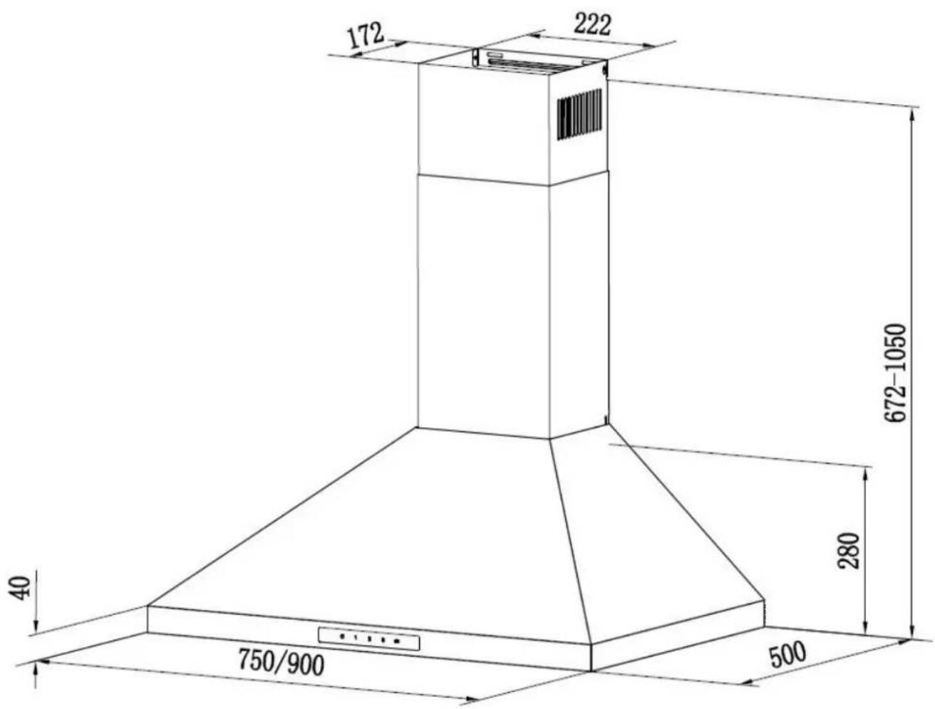
text_image
172 222 672-1050 280 40 750/900 5003.2 RANGEHOOD COMPONENTS
The Wall Canopy Rangehood is supplied with:
- 1 × Rangehood
• 1 × Expandable 150mm pipe - 1 × Packet of fasteners and wall plugs
- 2 × Stainless Steel flue pieces (upper and lower)
- 1 × Wall Bracket for the rangehood body
- 1 × Wall Bracket for the inside of the chimney piece
- 1 × Wall Bracket for the outside of the chimney piece
- 1 × User Manual
3.3 OPTIONAL ACCESSORIES
Following accessories can be purchased separately via contacting our Customer Servi
- Carbon Filter
- Various ducting solutions (rigid ducting, adapters, vents/outlets and elbow bends)
- Stainless Steel Flue extensions for various ceiling heights
4 INSTALLATION
4.1 INSTALLATION WARNINGS
Before starting the installation, please refer to the Safety Information section.
• Always switch the power off prior to beginning the installation.
- Ensure to handle appliance carefully as stainless steel can be easily damaged du installation.
- Wherever possible, protect the rangehood with the cardboard box or plastic
- A power point must be located within 1.5m of the power cord exit from the ran and should always be accessible to allow isolation from power during cleaning or maintenance.
- A 150mm round ducting adapter is supplied, however all other ducting accessories not.
- All ducting must comply with building codes and local requirements.
- If you are re-circulating the air, rather than ducting, please ensure that the side grilles are not obstructed in any way as this will affect the efficiency of the range
- Ensure that the rangehood is mounted in a level position, both horizontally and vertically. This is essential to ensure the rangehood operates correctly and prevents grease build up at one end.
IMPORTANT: Never use silicone around your rangehood or flue pieces. Never install the rangehood or flue pieces into the plaster ceiling which prevents easy access to the rangehood for servicing requirements.
IMPORTANT: Before installing your rangehood, please record the details of your rangehood's rating label. Usually this label is located inside the chamber behind the aluminium grease filters. This will be helpful should you need to contact for service in future.
4.2 INSTALLATION PREPARATION
TOOLS AND MATERIAL REQUIRED FOR INSTALLATION:
- Duct tape or cable ties
- Ducting relevant to your installation requirements (including any rigid bends, vents and/or adapters)
- Drill and/or screwdriver
- Spirit Level
-
Tape Measure
-
Jiqsaw
- Ladder
4.3 EXHAUST WAY SELECTION
Before beginning the installation of the rangehood, the method of ducting should be considered and selected.
NOTE: Most rangehoods can be operated in recirculation mode. For better operation and performance, it is recommended to duct vent outside wherever possible. The gu below illustrates the various ducting options. Below information is only a reference an most suitable way of ventilation shall be decided by professional installer.
DUCTING OUTSIDE MODE
Please follow the tips below on how to correctly duct your rangehood:
- Always use correctly sized ducting.
- Do not reduce the size of the ducting.
• Always use solid ducting.
• Always use non-flammable ducting. - Do not use flexible ducting.
- Do not duct into the ceiling space.
- Avoid sharp 90-degree bends as much as possible. Use 45-degree bends instead wherever possible.
- Duct to the outside using the shortest duct run possible.
-
Use cylindrical ducting whenever possible.
-
Into the ceiling cavity and then vented through your eaves
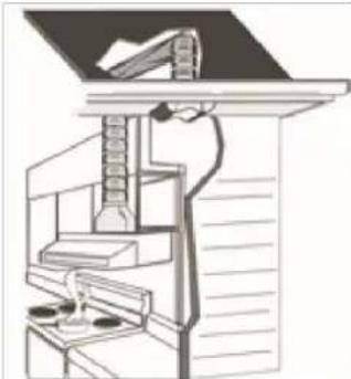
natural_image
Architectural diagram of a staircase with hand positioning and structural components (no text or labels)- Straight up and through the roof
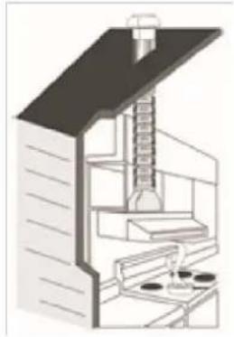
natural_image
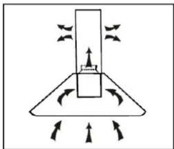
Cross-sectional diagram of a mechanical or architectural structure with layered components (no text or symbols visible)- Through the wall

natural_image
Diagram showing airflow patterns around a building structure and a mechanical component with directional arrows (no text or symbols)4.4 RECIRCULATION / DUCTLESS, VENT INSIDE OPTION
If the outside duct outlet is not available, most rangehoo able to operate recirculation mode.
The wall installation is shown above.
The activated carbon filters can be used to trap cooking and must be attached to the fan motor.
To install the carbon filter, the grease aluminum filter should be detached first. Press
lock and pull it downward.
natural_image
Diagram of a mechanical or fluid system with directional arrows and a central block (no text or symbols)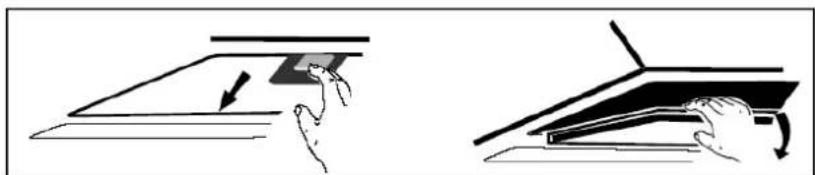
natural_image
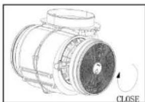
Illustration showing two hand-drawn diagrams of a mechanical or architectural component, one with an arrow and the other with a curved arrow (no text or symbols)Plug the activated carbon filte into the fan motor inlet and turn it in clockwise direction. If the motor requires two
repeat the same on the other side.
natural_image
Technical line drawing of an electric motor with a close button and rotating shaft (no text or symbols)NOTE:
- Make sure the filter is securely locked. If loose, it will cause danger.
- In recirculation mode, when activated carbon filter is attached, the suction power performance will be lower then in ducted outside mode.
4.5 POSITIONING THE RANGEHOOD
IMPORTANT: The height of the rangehood underside must be a minimum of 600mm to maximum 800mm from the top of your cooktop surface (for gas cooktops, this is the the gas burner).
NOTE: If the installation instructions for your cooktop specify a greater distance than minimum, then that shall be the minimum height for installation.
| COOKTOP FUEL TYPE: | DIMENSION A | |
| Minimum* | Maximum | |
| Gas(multiple burners with maximum 45.4 MJ/h total output at no single burner exceeding 16.2 MJ/h output) | 650mm | 800mm |
| Gas(multiple burners with total output greater than 45.4 MJ/h less than 77.8 MJ/h, and no single burner exceeding 17.3 output) | 760mm | 800mm |
| Gas(single burner not exceeding 21.6 MJ/h output) | 650mm | 800mm |
| Gas(single burner with an output greater than 21.6 MJ/h but exceeding 29.2 MJ/h) | 760mm | 800mm |
| Electric | 600mm | 800mm |
4.6 WALL INSTALLATION
- Set the installation height. Drill 3 holes to install the mounting bracket (hook) on the wall ensuring that it's secured in a level position. Tighten the bracket with screw plug and screw (ST4mm X 30mm).
- Line up the hood and hang onto the wall bracket hook (See Figure 1).
Figure 1

text_image
Figure 195 850-950
text_image
Holes on wall Screw plug Wall bracket Screw (ST4mm x 30mm)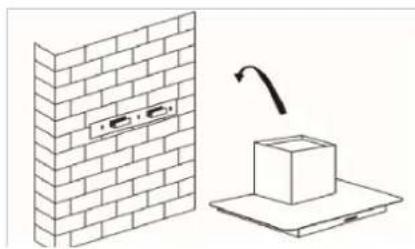
natural_image
Diagram showing a brick wall with a mounted component and a box on a platform, with an arrow indicating rotation (no text or symbols)- Attach the flexible 150mm tube to
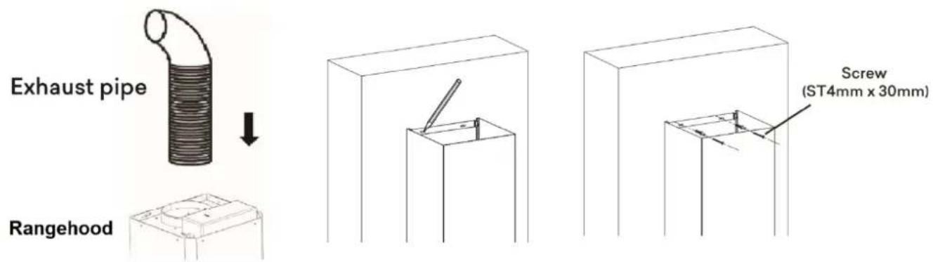
canopy. Put the inside chimney with the outside chimney together, ensuring that the inner chimney piece can move freely inside. Now attach the chimney to hood. When finished, fix the outside chimney to the canopy, mark the hole and 2 holes, then tighten the outside chimney bracket with screw plug and screw (ST4mm X 30mm) (See Figure 2).
Figure 2
text_image
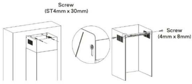
Exhaust pipe Rangehood Screw (ST4mm x 30mm)- If the safety screws need to be fixed into the hood, mark, drill and tighten the with screw plug and screw (ST4mm X 30mm).
NOTE: Remove the grease filters first (See Figure 3).
- Slide the inner chimney to adjust the inner chimney height. When the required height is reached, mark it and accommodate the inner chimney bracket with screw plug and screw (ST4mm X 30mm).
- When finished, fix the inner chimney with the screws (4mm X 8mm) to the inner chimney bracket (See Figure 3).
Figure 3
text_image
Screw (ST4mm x 30mm) Screw (4mm x 8mm)
text_image
Screw (4mm x 8mm) Safety screw (ST4mm x 30mm)5 USING RANGEHOOD
5.1 CONTROLS
The rangehood features touch controls with four speed levels of extraction.
When the rangehood is powered, the '1' button would appear illuminated.
This indicates the rangehood is now in standby mode. Press any of the keys to begin operation.
TOUCH CONTROL TO01
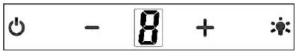
text_image
- 8 + *On/Off button
Fan turn on/off
+ Speed increase button
For increasing the speed of the fan
- Speed decrease button
For decreasing the speed of the fan.
Light button
8 Digital display
Fan speed display:"1" for Low speed, "2" for Medium speed, "3" for High speed.
Quick timer: Press & hold for 1 second. Digital display will turn flashing and rangehood switch into 5 minutes countdown mode. After 5 minutes motor and light turn off automatically and the buzzer sounds for 1 second.
SPEED SETTINGS
"1" Press the '1' button, the rangehood will operate at low speed.
Ideal for cooking with lower steam emissions such as slow cooking or simmering, boiling with closed pans.
“2” Press the ‘2’ button, the rangehood will operate at medium speed. This is the ideal standard intensity for a normal cooking environment.
“3” Press the ‘3’ button, the rangehood will operate at high speed. This is the ideal high intensity cooking such as grilling, intensive frying, wok cooking, stir frying, etc.
* Press the 'Light' button and the LED panel lights will turn on. To turn the lights off, simply push the 'Light' button again.
5.2 USING TOUCH CONTROLS
- The controls respond to touch, so you don't need to apply any pressure.
- Use the ball of your finger, not the tip.
- You will hear a "beep" like noise each time a touch is registered.
- Make sure the controls are always clean, dry, and that there is no object (e.g. a utensil or a cloth) covering them. Even a thin film of water may make the cold difficult to operate.
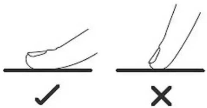
text_image
Diagram showing two hand positions on a surface with checkmark and cross symbols indicating correct and incorrect states.6 CARE AND MAINTENANCE
Proper cleaning and maintenance of this rangehood will ensure long fault free opera
natural_image
Warning symbol of a lightning bolt inside a triangle (no text or numbers)Warning!
Always switch off the electricity supply before performing maintenance work. In the event of fault, contact customer service.

natural_image
Simple diagram of a door with two rings and an 'OFF' label, no text or symbols presentCAUTION:
- Before maintenance or cleaning is carried out, the rangehood should be disconnected from the main power supply. Ensure that the cooker hood is switch-off at the wall socket and the plug removed.
- Stainless steel is susceptible to marks and abrasions, so please follow the cleanir instructions to ensure best possible results are achieved without damage.
- The instructions within this manual must be followed to avoid a fire risk.
- Keep the motor and other spare parts free from water as this will cause dama the appliance.
- Damaged power cables should be replaced by a qualified electrician
6.1 ALUMINIUM GREASE FILTER
- To remove the aluminium grease filter, use a finger to pull the small locking lat each filter to release it from the rangehood body. Be careful, as the filter car drop down once released and scratch or damage your cooktop.
- The filter collects grease, smoke and dust so the filter is directly affecting the efficiency of the cooker hood.
- If not cleaned, the grease residue (potentially flammable) will saturate the filter. Clean it with household cleaning detergent.
- Your aluminium filters can be washed by hand in warm soapy water. For stubborn grease stains, use a soft nylon brush to help remove these stains. After cleaning allow filters to completely dry before refitting into your rangehood.
CAUTION: The filters should be cleaned every few weeks of use to prevent fat and oil buildup and condensation. We do not recommend washing the aluminium filters in a dishwasher. This can damage the filter and cause discoloration of the filter. Cleaning the filter every month can prevent risk of fire.
6.2 STAINLESS STEEL SURFACES
Clean stainless-steel surfaces using non-abrasive cleaning products that are specifically designed to be used on stainless steel. To ensure best results, use even pressure and the grain of the stainless steel. Use of a soft cloth reduces the risk of scratching. If is wet, ensure that a dry soft cloth is also used to wipe down the surface afterwards reduce the risk of any surface rust appearing. Never use metal pads, chemical, abro material or stiff brushes to clean the unit.
6.3 CONTROL PANEL SURFACE
The control panel can be cleaned using warm soapy water. Ensure the cloth is well before cleaning. Use a dry soft cloth to remove any excess moisture left after clear
6.4 CHARCOAL FILTERS
If the rangehood has been installed in recirculating mode, you should be using the charcoal filter accessories available for purchase separately. These filters can not be used or cleaned and as a general rule the activated charcoal filter should be replaced every few months or more frequently depending on the amount and type of cooking
Annual Cleaning for Activated Carbon Filter
Apply when rangehood installed as a recirculation unit. The carbon filters must be replaced at least once a year depending on how frequent the cooker hood used.
To order a replacement filter, please contact our Customer Service.
6.5 CHANGING A LIGHT GLOBE
The LED lights should not require service. If it requires replacement, please check be or contact Customers Service for more information.
Replacing the bulb: Model BRR108 600, BRR108 900; 60cm/90cm \* LED Light\*
- Switch the unit off and unplug the appliance.
- Remove the stainless steel panel.
- Remove the light cover by unscrewing the 2
- Unscrew the broken light and replace with the same type and rated LED Light.

natural_image
Isometric diagram of a ceiling-mounted appliance with circular components and an upward arrow indicating direction (no text or symbols)Replacing the bulb: Model BRR129 900 \*LED strip\*
- Switch the unit off and unplug the appliance.
- Push the glass assembly out to the left.
- Unplug the LED strip light cable and switch wire, unscrew the four screws
- Take out the switch assembly and the 2 brackets.
- Take out the old LED strip light and replace the new LED strip light.

text_image
Technical diagram showing exploded view and assembly of a device with labeled components and directional arrowsReplacing the bulb: Model BRR206B900 \*Panel Light\*
- Switch the unit off and unplug the appliance
- Unplug the LED panel light cable.
- Unscrew the screws and nuts on the 2 brac
- Replace the LED panel light and screw back to the brackets.
- Plug the LED panel light cable back in.

text_image
Technical diagram showing a mechanical assembly with labeled components and a circular annotation pointing to a component.7 TROUBLESHOOTING
Before calling customer service, please check that the appliance is correctly connect. Any of the following cases are not covered by the warranty:
- Damage caused by improper use, storage or maintenance
- Damage caused by unauthorised disassembly and repair
• Damage caused by misuse
• Using the rangehood for commercial purposes
7.1 IN CASE OF EMERGENCY
In the event of an emergency you should:
- Switch off all rangehood controls.
- Switch the rangehood off at the power outlet and immediately unplug.
- Contact Customer Service.
Some minor faults can be fixed by referring to the instructions given in the table be
| FAULT | COMMON CAUSE | COMMON SOLUTIONS |
| The lights work, however the motor does not work | The motor is blocked or jammed. | Switch of the unit, arrange rep by a qualified technician |
| The capacitor is damaged | ||
| Neither the lights no the motor works | Beside the above mentioned, check the following: | |
| Light globes are damaged or blown | Replace the light globe | |
| The power cord is loose | Ensure that the rangehood is correctly plugged in and the power outlet is switched on. | |
| The rangehood is vibrating | The rangehood canopy is not fixed correctly. | Ensure that the internal safet screws have been used and are tight. |
| The unit is not hung properly on the bracket. | Remove the unit and check whether the bracket is in proper location, replace back ensuring it fully fits the bracket | |
| Insufficient suction | Too long distance between the rangehood and the cooktopDucting is loose, kinked, t long or too many bends | Re-adjust the installation positio ensuring that the minimum distances are observed as per building code and relevant standards.Check that your rangehood h been ducted correctly and in accordance with the installatio instructions. |
IMPORTANT: If your appliance appears to be operating incorrectly, then disconnect it your electrical supply and contact Customer Service.
WARNING: Do not attempt to repair the rangehood yourself.
NOTE: If a service technician is asked to attend whilst the product is under warranty finds that the problem is not the result of an appliance fault, then you will be liable cost of the service call.
The appliance must be accessible for the technician to perform any necessary repair your appliance is installed in such a way that the technician is concerned that dan will be caused to the appliance or your kitchen, then they will not complete a rep includes situations where appliances have been tiled in or sealed in with sealant. Please do not disassemble the unit by yourself to avoid any dangers and damages appliance, contact the supplier or Customer Service.
8 TECHNICAL SPECIFICATIONS
BRR108 600 SPECIFICATIONS
| Model | BRR108 600 |
| Dimensions(W × D × H) | 600mm × 500mm × 548-1028mm |
| Extraction | 1000m3/hr |
| Control | Touch TO01 |
| Speed settings | 3 |
| Lighting | 2x1.5w Multi Bulb LED light (LE01) |
| Filters | Aluminium perimeter extraction filter combined with internal |
| Power supply | 220–240 Volts 50HzConnects to standard household 10 Amp power point |
BRR108 900 SPECIFICATIONS
| Model | BRR108 900 |
| Dimensions(W × D × H) | 900mm × 500mm × 548-1028mm |
| Extraction | 1000m3/hr |
| Control | Touch TO01 |
| Speed settings | 3 |
| Lighting | 2x1.5w Multi Bulb LED light (LE01) |
| Filters | Aluminium perimeter extraction filter combined with internal |
| Power supply | 220–240 Volts 50HzConnects to standard household 10 Amp power point |
BRR129 900 SPECIFICATIONS
| Model | BRR129 900 |
| Dimensions(W × D × H) | 895mm × 485mm × 448-830mm |
| Extraction | 1000m3/hr |
| Control | Touch TO01 |
| Speed settings | 3 |
| Lighting | 1 × 6W LED strip |
| Filters | Aluminium perimeter extraction filter combined with internal filters |
| Power supply | 220–240 Volts 50HzConnects to standard household 10 Amp power point |
BRR206B900 SPECIFICATIONS
| Model | BRR206B900 |
| Dimensions(W × D × H) | 900mm × 500mm × 672-1050mm |
| Extraction | 1000m3/hr |
| Control | Touch TO01 |
| Speed settings | 3 |
| Lighting | 1 x 8W LED panel light |
| Filters | Aluminium perimeter extraction filter combined with internal filters |
| Power supply | 220–240 Volts 50HzConnects to standard household 10 Amp power point |
NOTE: Weight and Dimensions are approximate. Because we continually strive to improve our products we may change specifications and designs without prior notice.
9 DISPOSAL

natural_image
Symbol of a trash bin crossed with diagonal lines, representing waste sorting or disposal (no text or labels)This appliance requires special waste disposal. For further information regarding the treatment, recovery and recycling of this product please contact your local council, household waste disposal service or store of purchase.
The packaging materials are recyclable.

10 CUSTOMER CARE
- Please be advised that without the proof of purchase, your warranty may not be valid, keep the receipt.
For your convenience, please record:
STORE NAME/CONTACT DETAILS: ....
PURCHASE DATE: ....
PRODUCT MODEL N: ....
PRODUCT SERIAL N: ....
- The warranty will be voided, if not installed by a licensed professional.
For your own protection, please record installer's details:
Installer's Trade Name: ....
Trade Licence N: ....
Date of Installation: ....
Installation Receipt: ....
For further information on the appliance, service, spare parts or to obtain dimension installation information, please contact our customer service or visit website.
Please have above information and documents on hands before contacting customer service
Phone: 1300 615 001
Email: info@brohn.com.au
Web: brohn.com.au
