
AC561A-250 - AV Cable Black Box - Free user manual and instructions
Find the device manual for free AC561A-250 Black Box in PDF.

| Product Type | HDMI over CAT5 Receiver |
| Model | AC561A-250 |
| Brand | Black Box |
| Compliance | HDMI 1.2, HDCP 1.1, DVI 1.0 |
| Maximum Resolution | 1080p (output follows input) |
| Supported Cable Types | CAT5, CAT5e, CAT6 |
| Maximum Distance | 250 meters (configurable via DIP switch) |
| Connectors - Input | 2× RJ-45 (Video and DDC) |
| Connectors - Output | 1× HDMI female |
| Connectors - Power | 1× power connector (5 V DC) |
| Power Supply | 5 V DC, 2.6 A (with included adapter) |
| Dimensions (H × W × D) | 1.2 in × 4.8 in × 4.9 in (3 × 12.3 × 12.5 cm) |
| Weight | 1.5 lb (0.7 kg) |
| User Controls | Equalizer switch, Gain switch, DIP switch |
| Cleaning | Use a dry, soft cloth; avoid liquid cleaners |
| Safety | Use only supplied power adapter; keep away from moisture |
| Spare Parts | None user-replaceable; contact support for repairs |
| General | Extends HDMI signal over CAT5 cable up to 250 m; easy installation |
Frequently Asked Questions - AC561A-250 Black Box
User questions about AC561A-250 Black Box
0 question about this device. Answer the ones you know or ask your own.
Ask a new question about this device
Download the instructions for your AV Cable in PDF format for free! Find your manual AC561A-250 - Black Box and take your electronic device back in hand. On this page are published all the documents necessary for the use of your device. AC561A-250 by Black Box.
USER MANUAL AC561A-250 Black Box
© Copyright 2008. Black Box Corporation. All rights reserved.
1000 Park Drive • Lawrence, PA 15055-1018 • 724-746-5500 • Fax 724-746-0746
HDMI Receiver—50 m, 150 m, and 250 m

natural_image
Line drawing of a rectangular electronic device labeled 'HDMI OUTPUT' with a slot, shown without any additional text or symbols.CUSTOMER SUPPORT INFORMATION
Order toll-free in the U.S.: Call 877-877-BBOX (outside U.S. call 724-746-5500)
FREE technical support 24 hours a day, 7 days a week: Call 724-746-5500 or fax 724-746-0746
Mailing address: Black Box Corporation, 1000 Park Drive, Lawrence, PA 15055-1018
Web site: www.blackbox.com • E-mail: info@blackbox.com
FEDERAL COMMUNICATIONS COMMISSION AND
INDUSTRY CANADA
RADIO FREQUENCY INTERFERENCE STATEMENTS
This equipment generates, uses, and can radiate radio-frequency energy, and if not installed and used properly, that is, in strict accordance with the manufacturer's instructions, may cause interference to radio communication. It has been tested and found to comply with the limits for a Class A computing device in accordance with the specifications in Subpart B of Part 15 of FCC rules, which are designed to provide reasonable protection against such interference when the equipment is operated in a commercial environment. Operation of this equipment in a residential area is likely to cause interference, in which case the user at his own expense will be required to take whatever measures may be necessary to correct the interference.
Changes or modifications not expressly approved by the party responsible for compliance could void the user's authority to operate the equipment.
This digital apparatus does not exceed the Class A limits for radio noise emission from digital apparatus set out in the Radio Interference Regulation of Industry Canada.
TRADEMARKS USED IN THIS MANUAL
BLACK BOX and the Double Diamond logo are registered trademarks of BB Technologies, Inc.
Any other trademarks mentioned in this manual are acknowledged to be the property of the trademark owners.
Contents
Chapter Page
- Specifications....6
- Overview....7
2.1 Introduction....7
2.2 Features ....7
2.3 What's Included....8
2.4 Components ....8
- Installation and Operation....9
3.1 Front Panel 9
3.2 Rear Panel....10
1. Specifications
Resolution: HDMI: 480i/480p, 576i/576p, 720p @ 50/60 Hz; 1080i @ 50/60 Hz, 1080p @ 50/60 Hz
User Controls: AC561A-150: (1) Equalizer switch, (1) Gain switch; AC561A-250: (1) Equalizer switch, (1) Gain switch, (1) DIP switch
Connectors: Input: (1) RJ-45 CAT5 output for video, (1) RJ-45 CAT5 output for DDC; Output: (1) HDMI female; Power: (1) power connector
Power: 5 V/2.6 A DC power supply
Size: 1.2"H x 4.8"W x 4.9"D (3 x 12.3 x 12.5 cm)
Weight: 1.5 lb. (0.7 kg)
2. Overview
2.1 Introduction
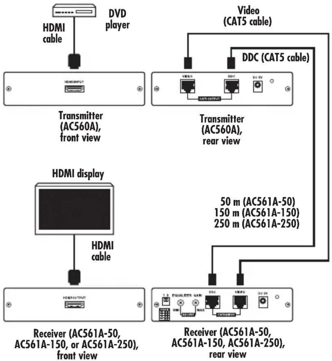
The HDMI Receivers (AC561A-50, AC561A-150, and AC561A-250) work with the HDMI Transmitter (AC560A). The HDMI over CAT5 transmitter can extend an HDMI signal through CAT5 cables for a distance of up to 50, 150, or 250 meters, depending on the receiver you choose. Installing the system is quick and easy: Simply place the receiver unit next to your display and the transmitter next to your HDTV source (such as a DVD player). Connect the required cables, as described in Chapter 3.
2.2 Features
- Complies with HDMI 1.2, HDCP 1.1, and DVI 1.0 specifications.
- Supports various types of CAT5/CAT5e/CAT6 cables.
- Supports high-definition input up to 1080p. Output resolution follows input.
- Easy to install and simple to operate.
2.3 What's Included
• HDMI Receiver (AC561A-50, AC561A-150, AC561A-250)
- 5-VDC power adapter
• (4) power clips for US, Europe, UK, and Australia
- This user's manual
2.4 Components
The receiver's front panel includes an HDMI output connector. All three of the AC561A models' rear panels have a DDC input connector, a video input connector, and a power connector. The AC561A-150's and AC561A-250's rear panels also have an equalizer switch and a gain switch. The AC561A-250 also has a DIP switch.
See Chapter 3 for illustrations and component locations.
3. Installation and Operation
3.1 Front Panel
Figure 3-1 shows the components on the Receiver's front panel. Table 3-1 describes the components' functions.
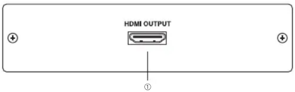
Figure 3-1. Receiver front panel.
Table 3-1. Receiver front-panel components and their functions.
| Number Component Name Description | ||
| 1 | HDMI output | Connect the HDMI output port to the HDMI input of your display. |
3.2 Rear Panel
Figures 3-2 through 3-4 show the components on the Receivers' rear panels. Table 3-2 describes the components' functions.

Figure 3-2. AC561A-50 receiver rear panel.

Figure 3-3. AC561A-150 receiver rear panel.
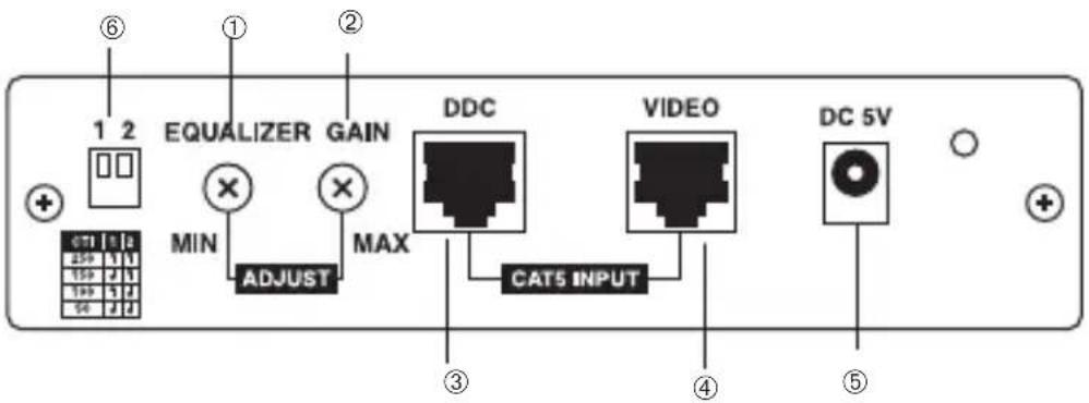
Figure 3-4. AC561A-250 receiver rear panel.
Table 3-2. Receiver rear-panel components and their functions.
| Number | Component Name Description | |
| 1 | *Equalizer Use this switch to adjust signal enhancement (AC561A-150 over long distance. and AC561A-250 *NOTE: (Figure 3-2 shows the AC561A-50 models only) | model; 1 and 2 are not present.) |
| 2 | *Gain Use this switch to adjust brightness. (AC561A-150 *NOTE: (Figure 3-2 shows the AC561A-50 and AC561A-250 models only) | model; 1 and 2 are not present.) |
| 3 | DDC input Using CAT5/CAT5e | CAT6 cable, connect the DDC input to the transmitter's DDC output. NOTE: For advanced users only, if the DDC or HDCP data are required for the source and the display, you can use a single CAT5 cable to connect the transmitter's and the receiver's video ports. |
HDMI RECEIVER—50 M, 150 M, AND 250 M
Table 3-2 (continued). Receiver rear-panel components and their functions.
| Number | Component Name Description | |
| 4 | Video input Using CAT5/CAT5e | CVCAT6 cable, connect the video input to the transmitter's video output. |
| 5 | Power Plug the 5-VDC power | supply into the receiver and connect the adapter to an AC wall outlet. |
| 6 | **DIP switch ***Selects cable (AC561A-250 model only) **NOTE: | length: 50, 100, 150, or 250 m(Figures 3-2 and 3-3 show the AC561A-50 and AC561A-150 models; 6 is not present.) |
Table 3-3. DIP switch settings for the AC561A-250.
| Length (meters) DIP Switch #1 DIP Switch #2 | ||
| 250 UP UP | ||
| 150 DOWN UP | ||
| 100 UP DOWN | ||
| 50 DOWN DOWN |
CHAPTER 3: Installation and Operation
flowchart
graph TD
    A["Transmitter (AC560A), front view"] --> B["HDMI INPUT"]
    C["Video (CAT5 cable)"] --> D["Transmitter (AC560A), rear view"]
    E["HDMI display"] --> F["HDMI cable"]
    G["Receiver (AC561A-50, AC561A-150, or AC561A-250), front view"] --> H["HDMI OUTPUT"]
    I["Receiver (AC561A-50, AC561A-150, AC561A-250), rear view"] --> J["DCI 1.3 EQUALITER GAIN"]
    K["Video (CAT5 cable)"] --> L[DCI 2.0 3.0 4.0 5.0 6.0 7.0 8.0 9.0 10.0 11.0 12.0 13.0 14.0 15.0 16.0 17.0 18.0 19.0 20.0 21.0 22.0 23.0 24.0 25.0 26.0 27.0 28.0 29.0 30.0 31.0 32.0 33.0 34.0 35.0 36.0 37.0 38.0 39.0 40.0 41.0 42.0 43.0 44.0 45.0 46.0 47.0 48.0 49.0 50.0 51.0 52.0 53.0 54.0 55.0 56.0 57.0 58.0 59.0 60.0 61.0 62.0 63.0 64.0 65.0 66.0 67.0 68.0 69.0 70.0 71.0 72.0 73.0 74.0 75.0 76.0 77.0 78.0 79.0 80.0 81.0 82.0 83.0 84.0 85.0 86.0 87.0 88.0 89.0 90.0 91.0 92.0 93.0 94.0 95.0 96.0 97.0 98.0 99.0
Figure 3-5. Typical installation.
- HDMI Receiver—50 m, 150 m, and 250 m
- CUSTOMER SUPPORT INFORMATION
- FEDERAL COMMUNICATIONS COMMISSION AND
- INDUSTRY CANADA
- RADIO FREQUENCY INTERFERENCE STATEMENTS
- TRADEMARKS USED IN THIS MANUAL
- Contents
- Chapter Page
- Specifications
- Overview
- Introduction
- Features
- What's Included
- Components
- Installation and Operation
- Front Panel
- Rear Panel
Brand : Black Box
Model : AC561A-250
Category : AV Cable