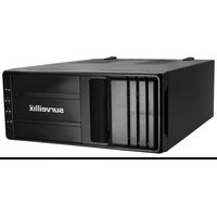
XVSV - Video camera TOSHIBA - Free user manual and instructions
Find the device manual for free XVSV TOSHIBA in PDF.


| Product Type | Digital Video Recorder (DVR) for surveillance |
| Brand | Toshiba |
| Model | XVSv |
| Analog Camera Inputs | Up to 16 (BNC connectors) |
| Network Camera Inputs | Up to 16 (IP cameras) |
| Video Compression | MJPEG, MPEG-4, H.264 |
| Recording Resolution | Up to 720x480 (NTSC) / 720x576 (PAL) |
| Maximum Recording Frame Rate | 480 PPS at 360x240 (NTSC) |
| Internal Storage | Up to 8 TB (hard drives) |
| Audio Inputs | Up to 16 channels |
| Sensor Inputs | Up to 16 (alarm inputs) |
| Relay Outputs | Up to 4 (alarm outputs) |
| PTZ Support | RS-485/RS-232, up to 4,000 ft via twisted pair |
| Video Outputs | VGA, HDMI, DVI-D, DisplayPort |
| Network Interface | Gigabit Ethernet (RJ-45) |
| Remote Access | Web Viewer, Remote Software, SCS, Mobile App |
| Operating System | Microsoft Windows 7 Embedded |
| Power Supply | 100-240V AC, 50/60 Hz (internal) |
| Warranty | 3 years limited (parts and labor) |
| Included Accessories | Mouse, keyboard, BNC cables (x2), power adapter, PTZ adapter, audio input cables, sensor cable |
| Compliance | FCC Class B |
| Mounting | Rack-mountable (instructions provided) |
Frequently Asked Questions - XVSV TOSHIBA
User questions about XVSV TOSHIBA
0 question about this device. Answer the ones you know or ask your own.
Ask a new question about this device
Download the instructions for your Video camera in PDF format for free! Find your manual XVSV - TOSHIBA and take your electronic device back in hand. On this page are published all the documents necessary for the use of your device. XVSV by TOSHIBA.
USER MANUAL XVSV TOSHIBA
Surveillix™ XVSv
Operation Manual (G6 Hardware & Version 5.0 Software)
Manual Edition 32861AA- July 2014
Printed in USA
No part of this documentation may be reproduced in any means, electronic or mechanical, for any purpose, except as expressed in the Software License Agreement. Toshiba shall not be liable for technical or editorial errors or omissions contained herein. The information in this document is subject to change without notice.
THE INFORMATION IN THIS PUBLICATION IS PROVIDED "AS IS" WITHOUT WARRANTY OF ANY KIND. THE ENTIRE RISK ARISING OUT OF THE USE OF THIS INFORMATION REMAINS WITH RECIPIENT. IN NO EVENT SHALL TOSHIBA BE LIABLE FOR ANY DIRECT, CONSEQUENTIAL, INCIDENTAL, SPECIAL, PUNITIVE, OR OTHER DAMAGES WHATSOEVER (INCLUDING WITHOUT LIMITATION, DAMAGES FOR LOSS OF BUSINESS PROFITS, BUSINESS INTERRUPTION OR LOSS OF BUSINESS INFORMATION), EVEN IF TOSHIBA HAS BEEN ADVISED OF THE POSSIBILITY OF SUCH DAMAGES AND WHETHER IN AN ACTION OR CONTRACT OR TORT, INCLUDING NEGLIGENCE.
This software and documentation are copyrighted. All other rights, including ownership of the software, are reserved to DVR Support Center. TOSHIBA, and Surveillix are registered trademarks of TOSHIBA CORPORATION in the United States and elsewhere; Windows, and Windows 7 are registered trademarks of Microsoft Corporation. All other brand and product names are trademarks or registered trademarks of the respective owners.
The following words and symbols mark special messages throughout this guide:
WARNING: Text set off in this manner indicates that failure to follow directions could result in bodily harm or loss of life.
CAUTION: Text set off in this manner indicates that failure to follow directions could result in damage to equipment or loss of information
The Imaging Systems Division of Toshiba America Information Systems, Inc. ("ISD") makes the following limited warranties. These limited warranties extend to the Original End-User ("You[r]").
Limited Three (3) Year Warranty of Labor and Parts
The Imaging Systems Division of Toshiba America Information Systems warrants this product and parts against defects in material or workmanship for a period of three (3) years from the date of original retail purchase by the end-user. The first year of the three year warranty period will cover advance replacement of a defective unit and the remaining two years will be repaired by the Surveillix DVR Support Center factory. During this period, ISD will repair or replace a defective product or part with a new or refurbished item. The user must deliver the entire product to the Surveillix DVR Repair Facility. The user is responsible for all transportation and insurance charges for the product to the DVR Repair Facility. ISD reserves the right to substitute Factory Refurbished Parts and / or Factory Refurbished Product in place of those in need of repair.
Step-by-step Procedures - How to Obtain Warranty Service
[1] Verify operation of the unit by checking the instruction manual and web site for the latest updates at
www.toshibasecurity.com
[2] If there is a defect in material or workmanship, contact the Surveillix DVR Support Center at (877) 855-1349 [877-855-1FIX] to speak to a technical support representative and schedule service.
[3] Arrange for delivery of the product to the Surveillix DVR Repair Facility. Products must be insured and securely packed, preferably in the original shipping carton. A letter explaining the defect and a copy of the bill of sale or other proof of purchase must be enclosed with a complete return street address and daytime telephone number. The Tracking Number should also be indicated on your documents. Charges for transportation and insurance must be prepaid by the end-user.
Critical Use Disclaimer
The product is not designed for any “critical applications.” “Critical applications” means life support systems, exhaust or smoke extraction applications, medical applications, commercial aviation, mass transit applications, military applications, homeland security applications, nuclear facilities or systems or any other applications where product failure could lead to injury to persons or loss of life or catastrophic property damage. Accordingly, Toshiba disclaims any and all liability arising out of the use of the product in any critical applications.
Your Responsibilities
The above warranty is subject to the following conditions:
[1] You must retain the bill of sale or provide other proof of purchase.
[2] You must schedule service within thirty days after you discover a defective product or part.
[3] All warranty servicing of this product must be made by the Surveillix DVR Repair Facility.
[4] The warranty extends to defects in material or workmanship as limited above, and not to any products or parts that have been lost or discarded by user. The warranty does not cover damage caused by misuse, accident, improper installation, improper maintenance, or use in violation of instructions furnished by ISD. The warranty does not extend to units which have been altered or modified without authorization of ISD, or to damage to products or parts thereof which have had the serial number removed, altered defaced or rendered illegible.
ALL WARRANTIES IMPLIED BY STATE LAW, INCLUDING THE IMPLIED WARRANTIES OF MERCHANTABILITY AND FITNESS FOR A PARTICULAR PURPOSE, ARE EXPRESSLY LIMITED TO THE DURATION OF THE LIMITED WARRANTIES SET FORTH ABOVE. Some states do not allow limitations on how long an implied warranty lasts, so the above limitation may not apply. WITH THE EXCEPTION OF ANY WARRANTIES IMPLIED BY STATE LAW AS HEREBY LIMITED, THE FOREGOING EXPRESS WARRANTY IS EXCLUSIVE AND IN LIEU OF ALL OTHER WITH RESPECT TO THE REPAIR OR REPLACEMENT OF ANY PRODUCTS OR PARTS. IN NO EVENT SHALL ISD BE LIABLE FOR CONSEQUENTIAL OR INCIDENTAL DAMAGES. Some states do not allow the exclusion or limitation of incidental or consequential damages so the above limitation may not apply.
No person, agent, distributor, dealer, service station or company is authorized to change, modify or extend the terms of these warranties in any manner whatsoever. The time within which an action must be commenced to enforce any obligation of ISD arising under this warranty or under any statute, or law of the United States or any state thereof, is hereby limited to one year from the date you discover or should have discovered, the defect. This limitation does not apply to implied warranties arising under state law. Some states do not permit limitation of the time within which you may bring an action beyond the limits provided by state law so the above provision may not apply to user. This warranty gives the user specific legal rights, and user may also have other rights, which may vary from state to state.
TOSHIBA AMERICA INFORMATION SYSTEMS, INC. Imaging Systems Division
Copyright © 2014 Toshiba America Information Systems, Inc. All rights reserved.
TOSHIBA
Leading Innovation >>>
IMPORTANT SAFEGUARDS
- Read Owner's Manual – After unpacking this product, read the owner's manual carefully, and follow all the operating and other instruction
- Power Sources – This product should be operated only from the type of power source indicated on the label. If you are not sure of the type of power supply to your home or business, consult your product dealer or local power company
- Ventilation – Slots and openings in the cabinet are provided for ventilation and to ensure reliable operation of the product and to protect it from overheating, and these openings must not be blocked or covered. The product should not be placed in a built-in installation such as a bookcase or rack unless proper ventilation is provided or the manufacturer's instructions have been adhered to.
- Heat – The product should be situated away from heat sources such as radiators, heat registers, stoves, or other products that produce heat.
- Water and Moisture – Do not use this product near water.
- Cleaning – Unplug this product from the wall outlet before cleaning.
- Power Cord Protection – Power-supply cords should not be routed so that they are not likely to be walked on or pinched by items placed against them, paying particular attention to cords at plugs, convenience receptacles, and the point where they exit from the product.
- Overloading – Do not overload wall outlets; extension cords, or integral convenience receptacles as this can result in a risk of fire or electrical shock.
- Lightning – For added protection for this product during storm, or when it is left unattended and unused for long periods of time, unplug it from the wall outlet. This will prevent damage to the product due to lightning and power line surges.
- Object and Liquid Entry Points – Never insert foreign objects into the NVR, other than the media types approved by Toshiba as they may touch dangerous voltage points or short-out parts that could result in a fire or electrical shock. Never spill liquid of any kind on the product.
- Accessories – Do not place this product on an unstable cart, stand, tripod, bracket, or table. The product may fall, causing serious personal injury and serious damage to the product.
- Disc Tray – Keep fingers clear of the disc tray as it is closing. Neglecting to do so may cause serious personal injury.
- Burden – Do not place a heavy object on or step on the product. The object may fall, causing serious personal injury and serious damage to the product.
- Disc - Do not use a cracked, deformed, or repaired disc. These discs are easily broken and may cause serious personal injury and product malfunction.
- LAN Port - This equipment is for indoor use and all the communication wirings are limited to inside of the building.
IMPORTANT SAFEGUARDS, continued
- Damage Requiring Service – Unplug the unit from the outlet and refer servicing to qualified service personnel under the following conditions:
a. When the power-supply cord or plug is damaged.
b. If liquid has been spilled, or objects have fallen into the unit.
c. If the unit has been exposed to rain or water.
d. If the unit does not operate normally by following the operating instructions. Adjust only those controls that are covered by the operating instructions as an improper adjustment of other controls may result in damage and will often require extensive work by a qualified technician to restore the unit to its normal operation.
e. If the unit has been dropped or the enclosure has been damaged.
f. When the unit exhibits a distinct change in performance - this indicates a need for service. - Servicing – Do not attempt to service this product yourself as opening or removing covers may expose you to dangerous voltage or other hazards. Refer all servicing to qualified personnel.
- Replacement Parts – When replacement parts are required, be sure the service technician has used replacement parts specified by the manufacturer or have the same characteristics as the original part. Unauthorized substitutions may result in fire, electric shock or other hazards.
- Safety Check – Upon completion of any service or repairs to this unit, ask the service technician to perform safety checks to determine that the unit is in proper operating condition.
BATTERY EXPLOSION CAUTION STATEMENT
CAUTION: Risk of Explosion if Battery is replaced by an Incorrect Type.
Dispose of Used Batteries According to the Instructions.
NOTES ON HANDLING
Please retain the original shipping carton and/or packing materials supplied with this product. To ensure the integrity of this product when shipping or moving, repackage the unit as it was originally received from the manufacturer.
Do not use volatile liquids, such as aerosol spray, near this product. Do not leave rubber or plastic objects in contact with this product for extended periods of time. Rubber or plastic objects left in contact with this product for extended periods of time will leave marks on the finish.
The top and rear panels of the unit may become warm after long periods of use. This is not a malfunction.
NOTES ON LOCATING
Place this unit on a level surface. Do not use it on a shaky or unstable surface such as a wobbling table or inclined stand.
If this unit is placed next to a TV, radio, or VCR, the playback picture may become poor and the sound may be distorted. If this happens, place the recorder away from the TV, radio, or VCR.
Do not use volatile liquids, such as an insect spray, near the unit. Do not leave rubber or plastic products touching the unit for a long time. They will leave marks on the finish. Do not use a chemically saturated cloth.
NOTES ON MAINTENANCE
To keep the recorder always operational we recommend regular inspection maintenance (cleaning parts or replacement). For details, contact the nearest dealer.
NOTES ON MOISTURE CONDENSATION
Moisture condensation damages the recorder. Read the following information carefully.
Moisture condensation occurs during the following cases:
When this product is brought directly from a cool location to a warm location.
When this product is moved to a hot and humid location from a cool location.
When this product is moved to a cool and humid location from a warm location.
When this product is used in a room where the temperature fluctuates.
When this product is used near an air-conditioning unit vent
When this product is used in a humid location.
Do not use the recorder when moisture condensation may occur.
If the recorder is used in such a situation, it may damage discs and internal parts. Remove any CD discs, connect the power cord of the recorder to the wall outlet, turn on the recorder, and leave it for two to three hours. After two to three hours, the recorder will warm up and evaporate any moisture. Keep the recorder connected to the wall and moisture will seldom occur.
WARNING
TO REDUCE THE RISK OF ELECTRICAL SHOCK, DO NOT EXPOSE THIS APPLIANCE TO RAIN OR MOISTURE.
DANGEROUS HIGH VOLTAGES ARE PRESENT INSIDE THE ENCLOSURE.
DO NOT OPEN THE CABINET.
REFER SERVICING TO QUALIFIED PERSONNEL ONLY.
CAUTION

CAUTION
RISK OF ELECTRIC SHOCK DO NOT OPEN

CAUTION: TO REDUCE THE RISK OF ELECTRIC SHOCK, DO NOT REMOVE COVER (OR BACK).
NO USER-SERVICEABLE PARTS INSIDE.
REFER SERVICING TO QUALIFIED SERVICE PERSONNEL.
RACK MOUNT INSTRUCTIONS
Elevated Operating Ambient – If installed in a closed or multi-unit rack assembly, the operating ambient temperature of the rack environment may be greater than room ambient. Therefore, consideration should be given to installing the equipment in an environment compatible with the maximum ambient temperature (Tma) specified by the manufacturer.
Reduced Air Flow – Installation of the equipment in a rack should be such that the amount of airflow required for safe operation of the equipment is not compromised.
Mechanical Loading – Mounting of the equipment in the rack should be such that a hazardous condition is not achieved due to uneven mechanical loading.
Circuit Overloading – Consideration should be given to the connection of the equipment to the supply circuit and the effect that overloading of the circuits might have on over current protection and supply wiring. Appropriate consideration of equipment nameplate ratings should be used when addressing this concern.
Grounding – Grounding of rack-mounted equipment should be maintained. Particular attention should be given to supply connections other than direct connections to the branch circuit (e.g. use of power strips).
FCC STATEMENT
INFORMATION TO THE USER: This equipment has been tested and found to comply with the limits for a Class B digital device, pursuant to Part 15 of the FCC Rules. These limits are designed to provide reasonable protection against harmful interference in a residential installation. This equipment generates, uses and can radiate radio frequency energy and, if not installed and used in accordance with the instructions, may cause harmful interference to radio communications. However, there is no guarantee that interference will not occur in a particular installation. If this equipment does cause harmful interference to radio or television reception, which can be determined by turning the equipment off and on, the user is encouraged to try to correct the interference by one or more of the following measures:
- Reorient or relocate the receiving antenna.
- Increase the separation between the equipment and receiver.
- Connect the equipment into an outlet on a circuit different from that to which the receiver is connected.
- Consult the dealer or an experienced radio/TV technician for help.
USERS OF THE PRODUCT ARE RESPONSIBLE FOR CHECKING AND COMPLYING WITH ALL FEDERAL, STATE, AND LOCAL LAWS AND STATUTES CONCERNING THE MONITORING AND RECORDING OF VIDEO AND AUDIO SIGNALS. TOSHIBA SHALL NOT BE HELD RESPONSIBLE FOR THE USE OF THIS PRODUCT IN VIOLATION OF CURRENT LAWS AND STATUTES.
Disclaimer
We disclaim any responsibility and shall be held harmless for any damages or losses incurred by the user in any of the following cases:
- Fire, earthquake or any other act of God; acts by third parties; misuse by the user, whether intentional or accidental; use under extreme operating conditions.
- Malfunction or non-function resulting in indirect, additional or consequential damages, including but not limited to loss of expected income and suspension of business activities.
- Incorrect use not in compliance with instructions in this user's manual.
- Malfunctions resulting from misconnection to other equipment.
- Repairs or modifications made by the user or caused to be made by the user and carried out by an unauthorized third party.
- Notwithstanding the foregoing, Toshiba's liabilities shall not, in any circumstances, exceed the purchase price of the product.
Usage Limitation
The product is not designed for any "critical applications." "Critical applications" means life support systems, exhaust or smoke extraction applications, medical applications, commercial aviation, mass transit applications, military applications, homeland security applications, nuclear facilities or systems or any other applications where product failure could lead to injury to persons or loss of life or catastrophic property damage.
Accordingly, Toshiba/TAIS disclaim any and all liability arising out of the use of the product in any critical applications.
Table of Contents
PREFACE....15
About this Guide ....15
Technician Notes 15
INTRODUCTION ....16
Product Description ....16
Features....17
CONTROLS AND CONNECTIONS....18
Front Panel Controls....19
XVSv 19
Rear Panel Connectors....20
XVSv 20
Card Configurations....21
240V PPS 16 Channel....21
GETTING STARTED....22
Identifying Included Components....23
Optional Components 24
Keyboard Setup....25
Mouse Setup....25
Monitor Setup ....26
Power Setup 26
Connecting a PTZ Camera....27
Turning on the recorder 28
Turning Off the recorder....28
DVR Basics 29
Setting the Time and Date ....30
Accessing the DVR Utility ....30
Exporting Settings 30
Importing DVR Settings 30
Changing Video Format....30
Display Screen....31
CPU Meter....31
Live Camera Options....32
Camera View ....33
Recording Status Indicator 33
Special Recording 33
Edit Live View Channels 34
Screen Division Buttons....34
Custom Live View Divisions....35
Setup Options....36
Setup Overview 37
Setup Menu Overvie 37
Analog Camera Setup....38
Set Up New Camera....38
Frame Setup....39
Maximum FPS Table 39
Network Camera Setup....41
Connecting a Network Device 41
Assigning Dual Streams 43
Removing a Camera....43
Assigning Audio Channels to a Network Device....44
Alarm Recording Mode 45
Camera Status and Information....46
DVR Registration and Upgrade 47
Unlocking Additional Network Devices 48
Motion DETECTION Setup....49
Create a Motion Area 49
Etc. 50
PTZ Camera Setup....51
Enabling an Analog PTZ Camera....51
Enabling an IP PTZ Camera....51
Using the Graphical PTZ Controller....52
Using the On-Screen Compass....52
General Setup....53
Audio ....53
Display....54
General....55
Sequencing....56
Alarms / Sensor 57
Alarms 57
Sensors ....57
Relays 58
Recording Schedule....59
Default Schedules 59
Day of the Week....60
Creating a Recording Schedule (Example) 60
Creating a Sensor Schedule (Example) 62
Special Day Schedule 63
Alarm Options....64
Setting a Restart Schedule....65
Network Setup 66
User Management 67
Changing the Administrator Password 68
Storage Management 69
Status Check / Email 69
SMART Information....72
Data Management....73
System Information....74
Log Files....76
Instant Recording....78
Activate Instant Recording....78
Searching 'Instant Recorded' Video 78
Search....79
Search Overview 80
Play Controls 80
Adjust the Brightness of an Image....81
Zooming in on an Image....81
Zooming in on a Portion of an Image....81
Open Video from a Saved Location....81
Sync 81
Clean Image 81
Performing a Basic Search 82
Printing an Image....82
Daylight SAVIng Time....82
Save to JPG or AVI....83
Bookmarks....84
Clip Backup 85
Index Search....86
Performing an Index Search....86
Index Search Results Display....86
Preview Search....87
Performing a Preview Search....88
Status Search 88
Performing a Status Search....88
Object Search....89
Performing an Object Search ....89
Motion Search....90
Performing a Motion Search....90
Audio Playback....90
Search in Live 91
Pan / Tilt / Zoom....92
Pan /Tilt / Zoom Overview....93
Basic PTZ Configuration....93
Advanced PTZ Setup....94
General....94
PTZ Presets/Tours 95
Accessing PTZ Menus....95
Controlling a PTZ Camera 95
Using the Graphical PTZ Controller....96
Using the On-Screen Compass....96
Understanding Tours 97
PTZ Tour Schedule 97
backing up Video Data 98
Backup Overview....99
Nero ® Express....99
General Backup Overview....100
Clip Backup Overview 101
Scheduled Screen Overview 102
Ian / isdn / pstn connections....104
LAN Overview....105
Connecting to a LAN Using TCP/IP 105
Configuring TCP/IP Settings....105
LDAP Integration....106
Features....107
Installing Active Directory....107
Web Viewer....109
Web Viewer Overview....110
Configuring the Recorder for Remote Connection....111
Connecting to a Recorder Using Web Viewer 111
Closing the Web Viewer 111
Included Software Setup 112
The Surveillix App Overview....113
Emergency Agent Overview 113
Configuring the Recorder 113
Configuring the Client PC 114
Setup Window 114
Emergency Agent Window 115
Search Alarm Window....116
Remote Software Overview 117
Remote Software Setup 118
Digital Verifier Overview....120
Installing the Digital Verifier....120
Using the Digital Verifier....120
Backup Viewer Overview....121
Installing Backup Viewer ....121
Loading Video from DVD or Hard Drive....121
SCS Overview 122
Connecting to a Recorder....122
PREFACE
ABOUT THIS GUIDE
This manual is a setup and maintenance guide that can be used for reference when setting up the recorder and for troubleshooting when a problem occurs. Only authorized personnel should attempt to repair this unit.
Toshiba reserves the right to make changes to the DVRs represented by this manual without notice.
The following text and symbols mark special messages throughout this guide:
Note Text set off in this manner indicates topics of interests that can help the user understand the product better.
Tip Text set off in this manner indicates topics and points of interests that can be helpful when using or settings up the DVR.
TECHNICIAN NOTES
Warning Only authorized technicians trained by Toshiba should attempt to repair this DVR. All troubleshooting and repair procedures that may be shown are for reference and minor repair only. Because of the complexity of the individual components and subassemblies, no one should attempt to make repairs at the component level or to make modifications to any printed wiring board. Improper repairs can create a safety hazard. And any indications of component replacement or printed wiring board modifications may void any warranty
Warning To reduce the risk of electrical shock or damage to the equipment:
- Do not disable the power grounding plug. The grounding plug is an important safety feature.
- Plug the power cord into a grounded (earthed) electrical outlet that is easily accessible at all times.
- Disconnect the power from the computer by unplugging the power cord either from the electrical outlet or the computer.
Caution To properly ventilate your system, you must provide at least 3 inches (7.6 cm) of clearance at the front and back of the DVR.
INTRODUCTION
PRODUCT DESCRIPTION

A Surveillix XVSv is a DVR, a server that performs as a High Definition Digital Recorder. By utilizing the many features of a computer, including processing power, storage capacity, graphics compression, and security features, the DVR is more powerful than the analog recorders of the past.
The Surveillix DVR server software comes pre-configured for fast and seamless integration within your existing IT infrastructure.
Designed around Microsoft® Windows 7 Embedded, the server software offers unparalleled stability, security, and ease of use.
Accordingly, your security investment has never been easier to maintain. Multiple users may simultaneously connect through any network connection for instantaneous live viewing, digital search, and off site video storage. Users can also connect remotely through DSL, Cable Modems, or ISDN. This powerful software enables users to establish recording schedules, create motion detection zones, use PTZ
controls, and configure alarm inputs and outputs for each of the system's cameras. With the latest advancements in the DVR Server Software, searching and indexing your video archive has never been easier. Video can now be found, viewed, and exported in a number of file formats with just a few clicks.
The Surveillix DVR is high performance security product ready to meet today's security demands.
Toshiba's Surveillix DVRs include the following new features:
- Optimized and Designed for Microsoft ® Windows 7 Embedded®
• Up to 16 Camera Inputs
• Supports up to 4 Relay Outputs on Alarm Activation
• Supports up to 16 Sensor Inputs for Alarm Control - Remote System Operation & Configuration
• Supports Multiple Simultaneous Remote Connections
• PAN / TILT / ZOOM Controls - Simultaneous Video Search, Playback and Backup
• Video Indexes for Easy Searching
• Multiple Levels of Security Access
• 1 Composite Outputs
• Up to 16 Network Recording Channels - Up to 16 Audio Inputs
• Output the Video to a NTSC/PAL Display - Up to 8 Terabytes internal storage
• Digital Signature Support - Hardware Watchdog
• Recording Resolution 720x480 / 720x240 / 360x240 NTSC
• Continuous, Motion Detection, Alarm, Pre-Alarm, and Scheduled Recording Modes
720x576 / 720x288 / 360x288 PAL
CONTROLS AND CONNECTIONS
This chapter includes the following information:
- Input / Output Connector Locations
• Front Panel Controls and LEDs - Rear Panel Connectors
FRONT PANEL CONTROLS
The front panel of the recorder contains the devices that will be commonly used for data removal, retrieval, and backup replacement. The most common components and buttons are shown below.
XVSv

The rear panel of the recorder contains the connectors used to attach cameras, sensors, and relays to the recorder. Below are diagrams that outline the location and description of each connector.
XVSv
16 Channel (240V)
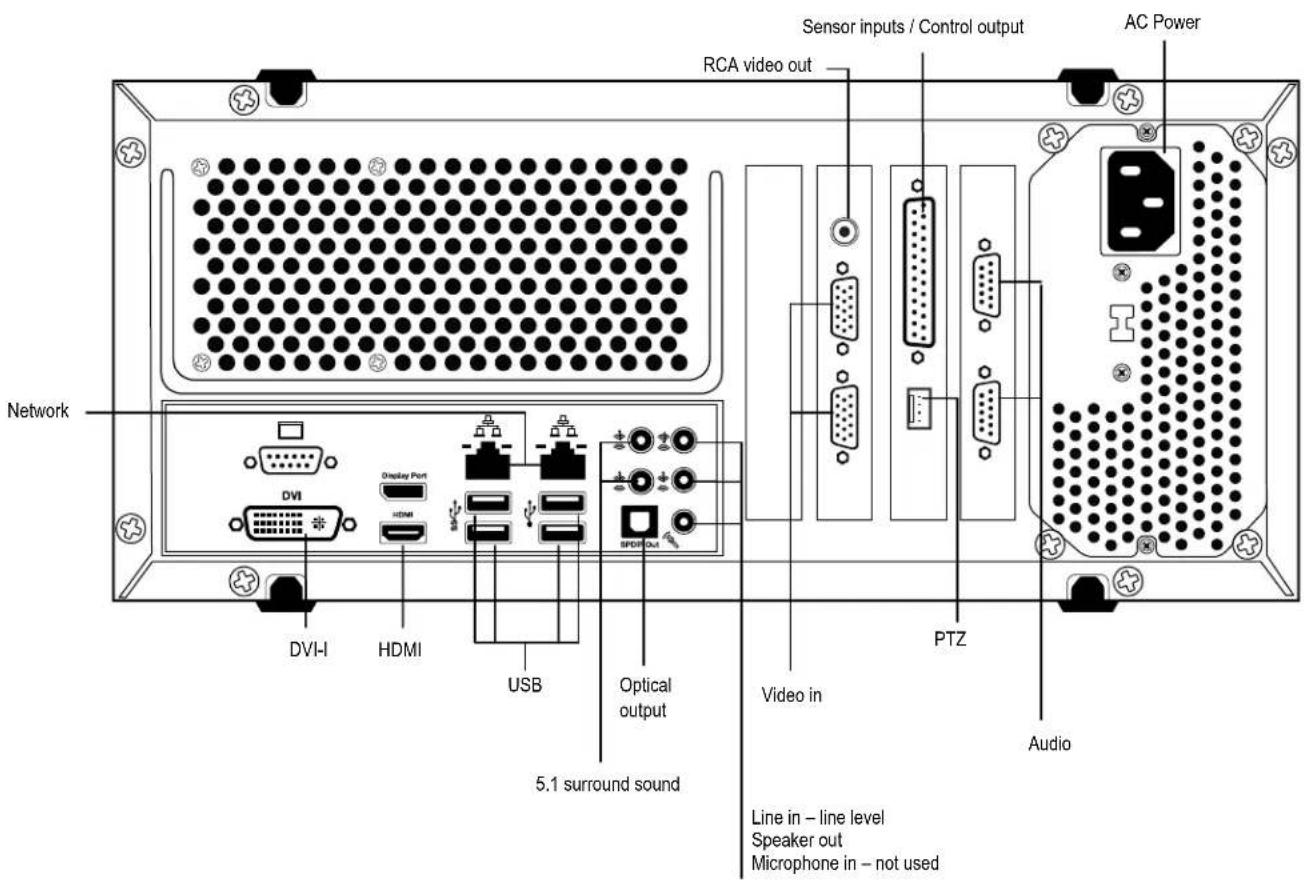
240V PPS 16 Channel
GETTING STARTED
This chapter includes the following information:
- Included Components
- Setting up the DVR Hardware
- Optional Components
IDENTIFYING INCLUDED COMPONENTS
Surveillix recorders come with a mouse, keyboard and selected software and cables. Identify the following components to make sure everything has been properly included with the new DVR. If any of the following items are missing, contact the dealer to arrange a replacement.
 Repair Disc / Software Disc Repair Disc / Software Disc |  Mouse Mouse |  Keyboard Keyboard |
 BNC Video Connector Cable (x2) BNC Video Connector Cable (x2) |  Power Adapter Power Adapter |  PTZ Adapter PTZ Adapter |
 8 Channel Audio Input Cable (x2) 8 Channel Audio Input Cable (x2) |  HDMI to DVI-D adapter HDMI to DVI-D adapter |  Sensor Input / Connector Output Cable Sensor Input / Connector Output Cable |
To fully utilize the recorder's potential; several optional Surveillix components are listed below. Contact the dealer for more information.
UPS UPS Power Backup
UPS Power Backups allow your DVR to remain fully functional even in the event of a power failure. UPS Power Backups also even the fluctuating power current out to provide a consistent, reliable power flow. This creates a stable environment for the DVR and reduces failure.
NP-4PKVM 4 Channel KVM Switch
The 4 Channel KVM switch allows you to have multiple boxes (up to 4) using only one keyboard, mouse and monitor. You can simply switch between the DVRs using the keyboard.
External RAID storage
An external RAID device is used for independent data reliability & provides much greater storage expandability.
Gigabit NIC
Provides support for Dual Nic configurations
SSD
Solid State Drive upgrade for the Operating System Boot drive.
Dual Gigabit NIC
Dual Gigabit Network Adapter with support for Teaming.
To attach the keyboard to the recorder, plug the end of the Keyboard into a USB port located on the back of the machine.

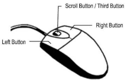
MOUSE SETUP
To attach the mouse to the recorder, plug the end of the mouse into a USB port located on the back of the machine.
The mouse uses a cursor called a pointer. Pointers come in many different shapes but are most commonly shaped like an arrow.
The mouse has two buttons: a left button and a right button. Quickly pressing and releasing one of these buttons is called clicking. Sometimes you will need to double-click – or click the same button twice quickly.
In this manual:
Click means to position the mouse cursor over an item and to single click the left button.
Right click means to position the mouse cursor over an item and to single click the right button.
Double-click means to position the mouse cursor over an item and to click the left button twice.
Select means to position the mouse cursor over a radio button, checkbox, or list item and click on it.
The scroll wheel in between the two buttons is used for added navigation functionality. By moving the wheel with index finger (scrolling), quickly move through multiple pages, lines, or windows. The wheel may also function as a third button allowing the user to quickly click or double-click an icon or a selected item
The recorder has the following connections available to attach a monitor.

HDMI Output
To TV / Digital Monitor
DVI -D Output
To TV / Digital Monitor
VGA Output
To VGA Monitor.
Display Port Output
To Digital Monitor
Attach the monitor or monitors to the rear of the recorder using the cable supplied by the monitor manufacturer. Refer to the monitor manual for detailed information on how to setup and use it.
Note The monitor must be capable of having a screen resolution of 1024 x 768 and display colors of at least 32 Bit
POWER SETUP

WARNING:
To reduce the risk of electrical shock or damage to the equipment:
Do not disable the power grounding plug.
The grounding plug is an important safety feature.
If the electrical plug you are using does not have a ground plug receptacle contact a licensed electrician to have it replaced with a grounded electrical outlet.
Plug the power cord into a grounded (earthed) electrical outlet that is easily accessible at all times.
Disconnect the power from the computer by unplugging the power cord either from the electrical outlet or the computer.
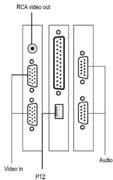
Connecting a PTZ Camera
Setting up a PTZ Camera is simple. The recorder comes preassembled with an internal PTZ adapter. The cabling may be run up to 4,000 ft using 22 Gauge Twisted Pair.
It is important to understand how the PTZ connects to the recorder. The recorder outputs an RS-232 signal and converts in to an RS-485 signal which is then sent to the PTZ camera.
Attaching the 4-Pin Adapter
- Locate the PTZ adapter cable
- Connect the wires of the PTZ adapter to the PTZ camera. The yellow wire should connect to the RX+ on the camera and the orange wire should connect to the RX-.
- Connect the other end of the adapter to the XVR unit as shown.
- Assign the PTZ camera an ID number in PTZ Setup that coincides with the number assigned to the camera. This is normally done utilizing a dip-switch configuration method on the addressable dome.
Example: If the camera is plugged into input number 5, set the PTZ unit to ID number.
RS-422

Once the cables and adapters have been properly connected it is time to turn on the power. To turn on the power follow these steps:
- Turn on the monitor and any external peripherals (ex. Printers, External Storage Devices, etc.) connected to the recorder.
- Turn on the Secondary Power Switch located in the rear of the recorder.
- Turn on the main power switch located on the front of the recorder.
The recorder will run a series of self-tests. After two or three minutes a series of messages may be displayed as the various hardware and software subsystems are activated. Under normal circumstances you should not be asked to respond to these messages. If you are asked to respond to the messages (adding a Printer, Monitor, etc for the first time) follow the instructions carefully.
After this finishes, the Surveillix recorder software should load automatically and bring you to the main screen.
To turn off the recorder, select the Exit button on the main screen and select Power Off. The recorder will safely shutdown, it may take several minutes to shut down completely.
Caution: Always be sure to follow the proper procedures when turning off the power to the recorder. NEVER disconnect the power to the recorder while it is still running or in the process of shutting down. Doing so can cause data loss, file corruption, system instability and hardware failure.
DVR BASICS
This chapter includes the following information:
- Becoming familiar with the Display screen
- Defining Screen Divisions
SETTING THE TIME AND DATE
- Exit to Windows by clicking Exit on the Display screen and then clicking Restart in Windows Mode.
- Click the Start button > Control Panel.
- Click Date and Time inside Control Panel.
- Adjust the Date and Time.
- When finished, click Apply, then OK, then close all open windows and restart the recorder. Do this by clicking Start and selecting Restart from the Shut Down menu.
ACCESSING THE DVR UTILITY
Exporting Settings
Exporting settings can help configure multiple recorders quickly or reconfigure a unit that has been reset to factory defaults. Some things must be kept in mind when using this feature.
You cannot use this function on:
• Recorders that are different models.
- When upgrading from certain software versions. (This feature cannot be used when upgrading from v2.x to v3.x)
1. Exit to Windows by clicking Exit on the Display screen then and select Restart in Windows Mode.
2. Click the Start button > All Programs > Surveillix > vFormat.
3. Click Export in the System Setting tool section.
4. Select a location to save the settings file and click Save. The DVR Utility will export the recorder settings and automatically close.

Importing DVR Settings
- Exit to Windows by clicking Exit on the Display screen then and select Restart in Windows Mode. (See the Display screen section later in this chapter)
- Click the Start button > All Programs > Surveillix > vFormat.
- Click Import in the System Setting Tool section.
- Select the location of the settings file to import and click Open.
- Click Yes to import the data file.
Changing Video Format
- Exit to Windows by clicking Exit on the Display screen then and select Restart in Windows Mode. (See the Display screen section later in this chapter)
- Click the Start button > All Programs > Surveillix > vFormat.
- Select the appropriate video setting from the list in the Video Setting section—NTSC or PAL.
- Click Set.
Each time the recorder starts, the program defaults to the Display screen. The following diagram outlines the buttons and features used on the Display screen. You should become familiar with these options as this is the screen that will be displayed the majority of the time.

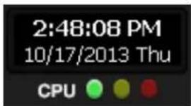
CPU Meter
Use the CPU meter to monitor the system resources on your recorder.
• GREEN - System configuration OK
- YELLOW - Caution; evaluate system configuration and consider decreasing system loading
- RED - System configuration has been exceeded which may affect stability; decrease system loading or upgrade system with CPU performance package
Live Camera Options
Right-click a camera on the Display screen to display these options:
- Full Screen – Expand the camera window to the full size of the screen.
- Instant Recording – Begin Instant Recording for the selected camera channel.
- Search In Live – Rewind or fast-forward video from that camera at the present date and time.
• 360 Setup – Configure settings for a 360 camera. - Enable 360 Camera – Enable the use of a 360 camera.
• e-PTZ – Use the digital PTZ function on a 360 camera
• View type – Select the view for a 360 camera
- Mount Type – Select the type of mount that matches the location of your 360 camera.
- Projection type – Dewarp your 360 camera image in Spherical or Flat view (Panogenics cameras only)
- Oncam SDK – Select to dewarp video footage from an Oncam 360 IP camera
• Panamorph SDK – Select to dewarp video footage from an Immervision 360 camera
• Panogenics SDK – Select to dewarp video footage from an AMG Panogenics 360 IP camera.

Note 360 Setup, Enable 360 Camera, e-PTZ, View Type, Mount Type, Projection Type, all require a 360 camera to function. If you do not have a 360 camera, ignore these functions.
![Recording Status TOSHIBA Camera Number and Name C2[Position2]](/content/2026/06/1148326/images/eb391536e189f767d17200bd78f28f1c929cb1d9ae58157760751085bc335bdf.jpg)
Recording Status Indicator
The camera status for each camera is displayed in the upper right corner on the Video Display Area. The following are the different states for each camera:

Recording
Displayed when the camera is currently being recorded to the recorder.

Motion Detection
Displayed when a camera (set up for motion detection) detects motion.

Display
Displayed when the camera is currently not being recorded to the recorder.
Special Recording
There are two types of Special Recording. Text is displayed on the camera indicating what type of Special Recording is activated.
SENSOR
Sensor is displayed when a sensor, associated with a given camera, is activated.
INSTANT
Instant Recording is a manual activation of the recording for the selected camera. Regardless of the recording method, Instant Recording will start the camera recording and also flag the video for future searches using the Index Search feature. INSTANT is displayed when a user activates the instant recording option. Right-click the video display to activate and deactivate the Instant Recording option.
By default, the recorder only allows live video from four network channels at one time on the local server. This protects the processor resources for recording data. The SCS software allows you to view live video from multiple recorders at once and with the same limitations that the recorder has on the number of live IP based video channels. If more than four channels of live video are required on the local server, you can enable the recorder to show up to 16 channels. Be aware that displaying 16 channels of live IP based video is resource intensive and may dramatically impact system performance.
To enable the recorder to view 16 channels of live video:
- Click Exit on the Display screen, and then select Restart in Windows Mode.
- Double-click the Edit Live View Channels icon on the desktop.
- Click Yes, and then click OK.
- The live view display will switch to 16 channel mode. To return the recorder to 4 channel mode, repeat steps 2 and 3.
- Double-click Surveillix Server to restart the recorder software.
The live view display will switch to 16 channel mode. To return the recorder to 4 channel mode, run the utility again using the same instructions.
SCREEN DIVISION BUTTONS
Note When viewing live video from Network Cameras, only 4CH will display at one time. If more live view channels are required on the local server, see the Edit Live View Channels instructions.

1st Four Cameras View – Displays cameras 1-4 in the Video Display Area. To return to a different Multi-Camera View, select a different Screen Division option from the Screen Division menu.

2nd Four Cameras View – Displays cameras 5-8 in the Video Display Area. To return to a different Multi-Camera View, select a different Screen Division option from the Screen Division menu.

3rd Four Cameras View – Displays cameras 9-12 in the Video Display Area. To return to a different Multi-Camera View, select a different Screen Division option from the Screen Division menu.

4th Four Cameras View – Displays cameras 13-16 in the Video Display Area. To return to a different Multi-Camera View, select a different Screen Division option from the Screen Division menu.

1st Nine Cameras View – Displays cameras 1-9 in the Video Display Area. To return to a different Multi-Camera View, select a different Screen Division option from the Screen Division menu.

2nd Nine Cameras View – Displays cameras 10-18 in the Video Display Area. To return to a different Multi-Camera View, select a different Screen Division option from the Screen Division menu.

Full Screen – The Full Screen Option allows you to view the Video Display Area using the entire viewable area on the monitor. When this is selected, no menu options are visible. You can activate the Full Screen Option by clicking on the Full Screen button within the Screen Division menu. You can deactivate Full Screen mode by right clicking on the screen.

Auto Sequence – Sequences through the Screen Divisions sets. For example, selecting the 1A and then the Loop button will sequence through 1A, 2A, 3A, 4A and then repeat.
Note Local screen division options are limited to ensure optimal encoding performance.
Custom Live View Divisions
Customize your Live View screen by changing the order of the cameras. Each screen division can be individually customized but a camera can only be displayed once in each group view.
Create custom live view divisions:
- On the Display screen, click Setup, and then click General Setup.
- Click the Sequencing tab.
- Drag and drop cameras from the Channel List to the desired location within the Division Group.

- Select the screen intervals you want to display in each division area.
- Set the Interval time (in seconds). This determines how long each sequence screen will appear on the Live display.
- To save your settings, click Apply.
SETUP OPTIONS
This chapter includes the following information:
- Setup Overview
- Camera Setup
- Network Video
- Motion
- General
- Frame Setup
- Schedule
- Sensor
- Network
- Administrative
• Information - PTZ
SETUP OVERVIEW
The Setup options allow you to optimize your recorder by adjusting things like camera names, restart schedules, recording schedules and more. It is extremely important that you setup your recorder correctly for several reasons.
- Recording Schedules – Increase the amount of pertinent recorded video that is saved on the recorder by optimizing the recording schedule. Optimize the type of recording done by adding motion detection to this as well, again increasing the amount of useful video.
- Camera Naming – Name each camera so the location can be easily identified and include any other pertinent information that may be helpful when viewing it on the Video Display Area.
- Configure Network Cameras – Connect to and configure cameras that are available on the network the recorder is connected to.
SETUP MENU OVERVIE
![graph TD A["Configuration"] --> B["Setup"] B --> C["Camera Setup"] C --> D["Analog Cameras"] C --> E["IP Cameras"] C --> F["Motion Detection"] C --> G["PTZ Setup"] G --> H["Recording Schedule"] H --> I["Alarms/Sensor"] H --> J["Network Setup"] J --> K["General Setup"] K --> L["User Management"] K --…](/content/2026/06/1148326/images/5db16784eec8947c432089078e36dd1418ea7e22e6d0c82dfcb0cfcdae5ebea1.jpg)
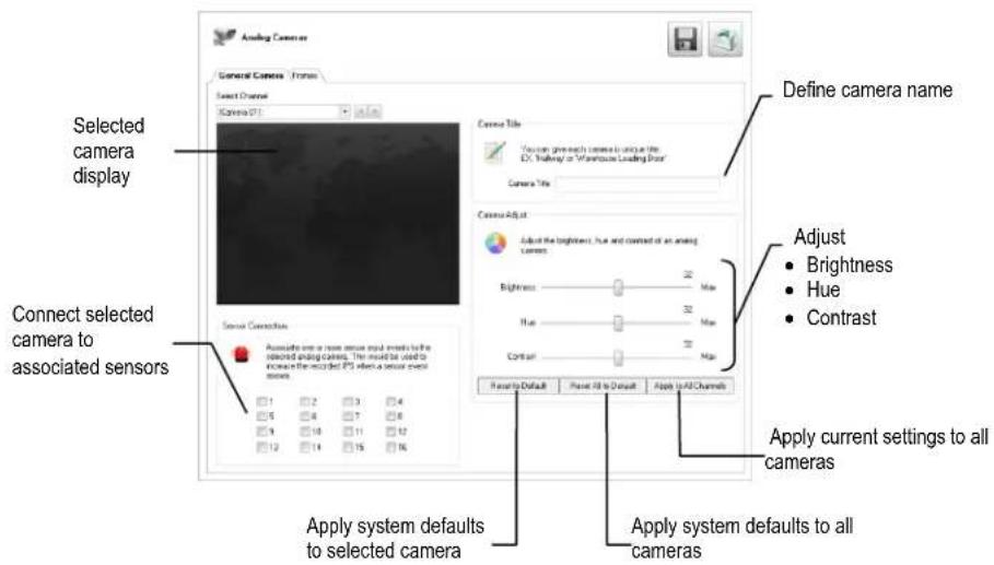
Select Channel
Select the camera channel to be edited.
Selected Camera Display
View the live camera feed from the selected camera channel.
Sensor Connection
Specify which sensors to associate with the camera selected.
Camera Name
Specify the name of the selected camera.
Set Up New Camera
- Use a BNC cable to connect your camera to the rear of the recorder chassis.
- On the Display screen, click Setup.
- Click Camera Setup, and then click Analog Cameras.
- Click the General Camera tab.
- Select the channel that corresponds with the new camera from the Select Channel list.
- Enter a name for the camera in the Camera Title field.
- Adjust the Brightness, Hue and Contrast if necessary.
- Select the appropriate Sensor Connection camera.
- Click Apply to save your settings.
The Frame Setup menu allows configuration of the Frames Per Second (FPS), resolution, quality, and sensitivity of camera channels. When configuring the FPS sliders, the blue slider represents the FPS the recorder will record during intensive recording and have available for transmitting to remotely-connected systems. The Red Slider represents the FPS that will be recorded by the recorder under normal recording conditions.
Note The total FPS of all blue sliders may not exceed the recording FPS of the recorder (based on model). The FPS of a red slider may not exceed that of the blue slider for the same channel.
Note If MJPEG is selected as the recording codec, the dual sliders allow configuration of the recorder to record at a lower FPS while still being able to view live video and transmit video at a higher FPS to remote connections. For example: If a camera channel is set to 25 FPS (blue) and 7 FPS (red), the recorder will record at 7 FPS and users viewing live video at the recorder or remotely can receive up to 25 FPS.
Maximum FPS Table
FPS Breakdown for Each Resolution
| Resolution | CCTV | x480 model | x240 model |
| 360x240 | 1CIF | 480 PPS | 240 PPS |
| 720x240 * | 2CIF | 240 PPS | 120 PPS |
| 720x480 ** | 4CIF | 120 PPS | 60 PPS |
* Frames recorded in 720 x 240 are twice the size of the standard 360 x 240. When recording at 720 x 240, each frame assigned to the channel will use two of the local frames available.
** Frames recorded in 720 x 480 are four times the size of the standard 360 x 240. When recording at 720 x 240, each frame assigned to the channel will use four of the local frames available.
Frame Setup (XVSe & XVSv)

Note The red FPS record slider cannot exceed the blue FPS capture slider
Note The software will not allow the maximum available frames to be exceeded.
Note Using H.264 software compression significantly increases the processing load on the Surveillix DSVe and XVSe platforms. If maximum analog PPS is desired in addition to IP video recording or multiple remote clients, Surveillix engineering recommends the addition of the upgraded system CPU (DVR-CPU UPG).
Frame Select
Blue Slider: Set the frame rate to be recorded during intensive recording and available for viewing on a remote client PC.
Red Slider: Set the frame rate recorded by during normal recording.
Resolution
Adjusting resolution will affect the total number of frames per second that are available.
Codec
Select the appropriate codec for each camera: MJPEG, MPEG-4, or H.264.
Video Quality
Lower quality video has a smaller file size but appears more pixilated.
Sensitivity
Set the Keyframe refresh rate. Adjusting this setting can result in poor video quality.
Note Do not change the default setting unless instructed by a system administrator.
Connect IP cameras to your recorder using a network switch, which is connected to the network port on your recorder. By default, your recorder can display 4 IP camera channels in the Display screen. To change this setting, see the Edit Live View Channels section.
Connecting a Network Device

Use Global Camera Setup – Change camera quality, frame rate, and resolution settings for all connected cameras by enabling this function and making changes to one camera. This function is only supported by ONVIF cameras.
Global Credentials – When using Global Camera Setup, select Global Credentials, and then type the User Name and Password for your selected cameras to add them to your system.
Select All – Select all of the cameras included in the Device Search list.
Dismiss All – De-select all the cameras you have selected in the Device Search list.
Connecting Manually
- On the Display screen, click Setup.
- Click Camera Setup, and then click IP Cameras.
- Click Manually Add Camera.
- Select the Vendor and Model of your network device from the Device Type list.
- Type a Device Name.
- Type the IP/URL address, Port#, User ID and Password of the device.
- Click Add.
- Double-click in the Channel field, and then select the Channel you want to assign to this camera.
- Click Apply.
Note Audio is not supported when using ONVIF as the Driver/Type when connecting to IP cameras. If audio is needed, select the native integration method to connect the camera.
Connecting with Find Cameras
- On the Display screen, click Setup.
- Click Camera Setup, and then click IP Cameras.
- Click Find Camera to automatically find all connected Network cameras.
- Select the check box next to your desired camera.
- Type the User ID and Password of the device.
- Click Add Selected.
- The camera will appear in the Camera Setup tab.
- Double-click in the Channel field, and then select the Channel you want to assign this camera to.
- Click Apply.
Naming Camera Channels
Surveillix recommends assigning a descriptive name to each camera channel for easy identification of where the camera is located. To name your IP camera channels, follow these instructions.
- On the Display screen, click Setup.
- Click Camera Setup, and then click IP Cameras.
- Click the Camera Setup tab.
- Double-click the Device Name column for the camera you want to name.
- Type a name for your camera.
- Click Apply to save the name.
Assigning Dual Streams
Dual stream support enables you to take advantage of two different streams from an IP camera. One stream can be high definition forensic video, while the other stream can be a lower resolution for live display. This allows SCS or Remote Viewer software to display more cameras while utilizing lower bandwidth and less CPU usage.
The second stream is used for motion detection in the server, which lightens the processing load for centrally-managed motion detection configurations
Dual streaming functions are limited to cameras that support this feature.
- On the Display screen, click Setup.
- Click Camera Setup, and then click IP Cameras.
- Click the Camera Setup tab.
- Choose which camera you want to configure, and double-click the Record Stream column.
- Select which Stream you want to assign to be recorded.
- Double-click the Transmit Stream column and choose the appropriate stream for remote viewing.
- Click Apply to save your selections.
Removing a Camera
To remove a camera from your system, follow these instructions.
- On the Display screen, click Setup.
- Click Camera Setup, and then click IP Cameras.
- Click the Camera Setup tab.
- Right-click the camera you want to remove on the Network Cameras Currently in Use list, and then click Remove Device.
- Click Yes to finish removing the camera.
- Click Apply to save your settings.
Assigning Audio Channels to a Network Device
- In the Display screen, click Setup.
- Click IP Cameras.
- Click the Camera Setup tab.
- Click the Advanced Camera Setup tab.

IP Cameras
Camera Setup Camera Status and Information
Network Cameras Currently in Use
| Channel | Device Name | Model | User Name | Password | Port | Record Stream | Resolution | Capt |
| 2 | 10.89.90.80 | IK-WB81A | root | 8080 | Stream 1 | |||
| 3 | 169.254.79.28 | IK-WB81A | root | 8080 | Stream 1 | |||
| 4 | 10.89.90.199 | IK-WD04A/IK-... | root | 8080 | Stream 1 | |||
| 5 | 169.254.140.233 | IK-WD04A/IK-... | root | 8080 | Stream 1 | |||
| 6 | 169.254.0.99 | IK-WB30A/IK-... | root | 80 | Stream 1 | |||
| 7 | 10.89.90.105 | IK-WD01A/IK-... | root | 80 | Stream 1 | |||
| 8 | 169.254.72.109 | IK-WD04A/IK-... | root | 8080 | Stream 1 | |||
| 9 | 10.89.90.109 | IK-WD04A/IK-... | root | 8080 | Stream 1 |
Use Global Camera Setup
Manually Add Camera
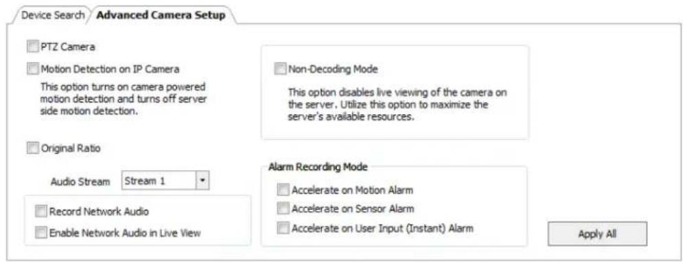
Device Search Advanced Camera Setup
PTZ Camera
□ Motion Detection on IP Camera
This option turns on camera powered motion detection and turns off server side motion detection.
Non-Decoding Mode
This option disables live viewing of the camera on the server. Utilize this option to maximize the server's available resources.
Original Ratio
Audio Stream

Record Network Audio
Enable Network Audio in Live View
Alarm Recording Mode
Accelerate on Motion Alarm
Accelerate on Sensor Alarm
Accelerate on User Input (Instant) Alarm
Apply All
- Select the camera you want to record audio from in the Network Cameras Currently in Use field.
- Select Record Network Audio.
- To be able to hear audio from the recorder, select Enable Network Audio in Live View.
- Click Apply to save your settings.
Alarm Recording Mode
Set your camera to trigger Intensive Recording via Motion detection, Sensor Alarms, or user-instigated Instant Alarm.
- On the Display screen, click Setup.
- Click Motion Detection, and then click the Etc. tab.
- Select your desired camera channel from the Select Channel list.
- Select Enable Motion Detection on Continuous Recording.
- On the Configuration menu tree, click IP Cameras.
- Click the Camera Setup tab.
- Click the Advanced Camera Setup tab.
- Select the camera you want to record audio from in the Network Cameras Currently in Use field.
- Select your desired Intensive Recording Mode (Accelerate on Motion Alarm, Accelerate on Sensor Alarm, or Accelerate on User Input (Instant) Alarm).
- Click Apply to save your settings.
Note When using H.264 codec, your recorder will capture iFrames at a normal recording rate, and increase to full frames for Intensive Recording.
Camera Status and Information
The Camera Status and Information tab displays information on all cameras connected to the recorder.

IP Cameras


Camera Setup Camera Status and Information
Monitoring
| Channel | Camera Name | Record Stream | Resolution | Capture IPS | Record IPS | Transmit Stream | Resolution | Capture |
| 1 | Position 1 | |||||||
| 2 | 10.89.90.80 | Connected | 1920 × 1080 | 20 | 0 | Connected | ||
| 3 | 169.254.79.28 | Connected | 1920 × 1080 | 20 | 0 | Connected | ||
| 4 | 10.89.90.199 | Connected | 1280 × 800 | 15 | 0 | Connected | ||
| 5 | 169.254.140.233 | Connected | 1280 × 800 | 15 | 0 | Connected | ||
| 6 | 169.254.0.99 | Connected | 0 | 0 | Connected | |||
| 7 | 10.89.90.105 | Connected | 640 × 480 | 5 | 0 | Connected | ||
| 8 | 169.254.72.109 | Connected | 1280 × 800 | 19 | 0 | Connected | ||
| 9 | 10.89.90.109 | Connected | 1280 × 800 | 19 | 0 | Connected | ||
| 10 | 10.89.90.111 | Connected | 640 × 480 | 10 | 0 | Connected | ||
| 11 | 10.89.90.107 | Connected | 1280 × 960 | 8 | 0 | Connected | ||
| 12 | Position 12 | |||||||
| 13 | Position 13 | |||||||
| 14 | Position 14 | |||||||
| 15 | Position 15 | |||||||
| 16 | Position 16 | |||||||
Device Setup
- In the Display screen, click Setup.
- Click IP Cameras.
- Click the Camera Status and Information tab.
DVR Registration and Upgrade
Have the following information available before registering the DVR upgrade.
Product Serial Number: This may be the Product Serial Number displayed on the product sticker on the left side of the recorder; or the unique Product Serial Number provided with the purchase of additional channel licenses.
System ID: The System ID is a number that is generated by the recorder. This is a unique code generated using the MAC address of the recorder.
Locating the System ID
- On the Display screen, click Setup.
- Click IP Cameras.
- Click the License tab.
License Information
System ID
72759F913BE34D
Copy
License Key
Register
Channel Connection License
| License Key | Total | Used | Free |
Obtaining the License Key
- Open an Internet browser and go to: http://register.surveillixdvrsupport.com
- Enter the Product Serial Number and System ID.
- Click Submit.
- Verify the information, and click Next.
- The Unlock Code provided will need to be entered into the License Key field on the recorder.
Note Both the System ID and the Unlock Code are case sensitive.
Note We recommend printing the registration page with the Unlock Code for later reference.
Unlocking the Upgrade
- Return to Setup > Network Cameras > License.
- Enter the Unlock Code generated by the Registration Site into the License Key box.
- Click Register and confirm that the new License Key is listed in the Channel Connection License box.
- Click OK.
- Click Apply.
- Click Exit Setup.
Unlocking Additional Network Devices
Follow the instructions above for Registration and Upgrade to unlock any additional network devices.
The recorder allows the user to adjust several different Motion Settings and create motion detection areas.

Create a Motion Area
- On the Display screen, click Setup.
- Click Motion Detection.
- Select a camera from the Select Channel list.
- Select Detect Detail Motion Area.
- Click Clear Motion Area.
- Click Setup Advanced Motion Area.
- Click a Motion Detection Area shape button.
- Drag the mouse over the camera image.
Note To create a polygon shape, click the mouse at each point and double-click to close the shape.
-
Click OK.
-
Move the sliders to adjust motion sensitivity and the noise filter.
- Define the pre-alarm and post-alarm recording time for a motion event.

Select Existing Motion Shapes

Draw Square Motion Detection Area

Draw Polygon Motion Detection Area

Draw Circle Motion Detection Area

Draw Square Non-Motion Detection

Draw Polygon Non-Motion Detection

Draw Circle Non-Moton Detection Area

Select All Motion Detection areas

Delete All Motion Detection areas

Pre Alarm Recording - 0 - 120 Seconds [The number of seconds the recorder records before motion is detected—to ensure any motion occurring between l-frames is captured, set to a value greater than 0]
Post Alarm Recording - 0 - 120 Seconds [The number of seconds the recorder records after it stops detecting motion]
Etc.
Additional motion detection configuration options are found on the Etc. tab. Use this tab to set a camera channel to appear at full screen in the Display screen when a motion or sensor event is detected. You can also set your recorder to enable motion detection even during continuous recording, or play an audio warning when an alarm event is detected.
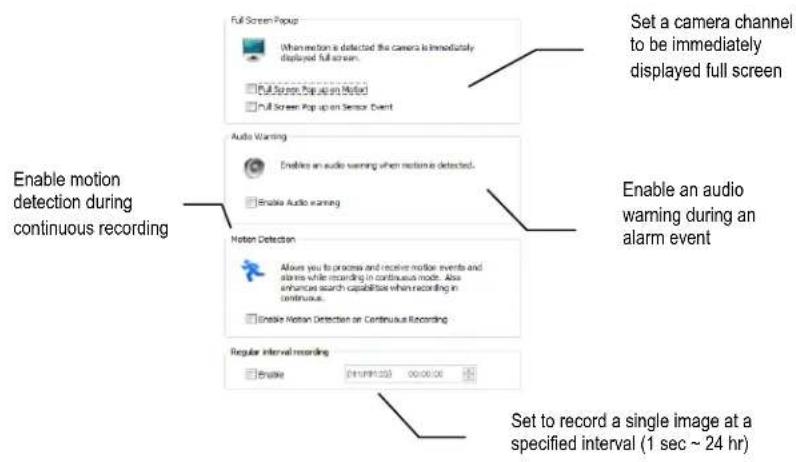
Note It is not recommended to enable Full Screen Pop Up on Motion for all channels (either manually, or by clicking Apply to All Channels). This will cause performance problems.
PTZ cameras can be configured and controlled using the Surveillix recorder software. For instructions on configuring and installing your PTZ camera, refer to the camera manual.
Enabling an Analog PTZ Camera
- Ensure that you have properly connected your analog PTZ camera to the recorder.
- On the Display screen, click Setup.
- Click Camera Setup, and then click PTZ Setup.
- Click Select Channel, and then click the analog channel you want to enable as a PTZ camera.
- Click Enable Pan Tilt Connection.
- Type the appropriate Protocol, Port, Baud Rate, Parity, Data Bits and Stop Bits for your analog PTZ camera. These must be the same settings that have been configured on the camera itself.
- Set the appropriate General and Preset/Tours options.
- Click Apply to save your settings.
Note For more information regarding creating preset positions, PTZ tour schedules, and controlling your PTZ camera, please refer to the Pan/Tilt/Zoom chapter of this manual.
Enabling an IP PTZ Camera
- Ensure that you have properly connected your IP PTZ camera to the network.
- On the Display screen, click Setup.
- Click IP Cameras, and then click Advanced Camera Setup.
- Select the IP camera from the Network Cameras Currently in Use list.
- Select PTZ Camera.
- Click Apply to save your settings.
Using the Graphical PTZ Controller
- In the Display screen, click Pan/Tilt.
- Click the viewing area of the PTZ camera you want to control.
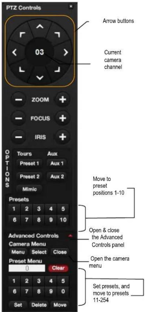
- Use the Arrow buttons to control the direction of the PTZ camera.
- To select a new camera, click the video display of a different camera on the Display screen display.
Note Eight directions are available only for select cameras. Only four of the PTZ Control buttons work for all protocols (UP, DOWN, LEFT, RIGHT).
Note The Advanced menu panel on the graphical PTZ controller can be used to set PTZ preset positions (on supported cameras), as well as move to presets up to 254.
- To exit the Graphical PTZ Controller, click Pan/Tilt again.
Note To access the OSD menu on Toshiba PTZ cameras, type 95 in the Preset Menu field, and then click Set.
Using the On-Screen Compass
- On the Live screen, click Setup.
- Click PTZ Setup.
- Select the Camera Channel of the PTZ camera you want to enable Onscreen Compass control for.
- In the General tab, select Onscreen Compass.
- Click Apply.
- Close the Setup window to return to the Live screen.
- Click Pan Tilt.
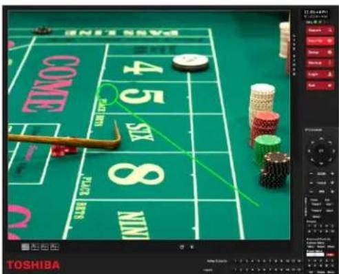
- Control the PTZ camera by clicking and dragging the mouse on the screen in the desired direction.
Note A green line will appear to show the direction in which the PTZ camera will move. The shorter the line, the less the PTZ will move. The longer the line, the more the PTZ will travel in the specified direction.
To access the General Setup window, click Setup in the Live screen, and then click General Setup.
Audio
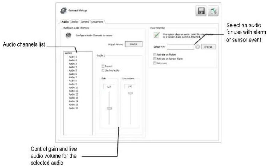
The Audio tab allows you to configure audio channels, audio playback, and set a voice warning.
Configure Audio Channels
System Volume
- Click Volume to adjust the volume of your system.
- Use the slider, enter a value, or click Mute to disable audio playback.
- Click OK.
Audio Channels
- Select an Audio Chanel.
- Select Record and Use Live Audio, as desired.
- Adjust the gain and Live Volume for each channel, depending on your desired output and microphone sensitivity.
- Click Apply to save your settings.
Voice Warning
The recorder allows users to play a sound file when either a Motion event or Sensor event occurs. This file can be a custom created sound file that is unique to the application. The selected WAV file is played through speakers attached to the recorder.
- Click Browse, and then locate your .wav file.
- Click Play to test the file.
- Select Activate on Motion or Activate on Sensor Alarm to activate this warning whenever that event occurs.
- Click Apply to save your settings.
Display
The Display tab allows you to control the on-screen appearance of your recorder, including the resolution and configuration of multiple monitors.

Motion Bounding Box – Select Display Motion Detection Area Box to see a colored boundary highlighting the area motion occurs.
Sensor / Relay Status Bars – Select Display Sensor Status Bar or Display Relay Status Bar to see icons when sensors or relays are activated.
Live Decoding – Select Enable Key Frame Display for IP Cameras to reduce the processing load by only displaying key frames.
Live Afterimage Filter – Select Live Afterimage Filter to reduce motion blur in images from analog cameras if necessary.
Display Options
- To allow the display resolution to automatically adjust to the resolution of any monitor, select Force Window to Full Screen.
- To manually select a resolution, clear Force Window to Full Screen, and then click Select Resolution.
- To change the font of your On Screen Display, click Select.
- Select your desired Font and Size. Select Bold if desired.
- When you have selected your font, click OK.
- Select Hide Network Connectivity Status from Live View if desired.
- Click Apply to save your settings.
General
Use the General tab to configure your overall backup options.
Backup

Configure general backup options
√ Automatically include the Backup Viewer Application with backup
Enable CD/DVD Backup
Automatically Include the Backup Viewer Application with Backup – Disabling this option will require Backup Viewer to be manually installed on a computer before viewing the video.
Enable CD/DVD Backup – Disabling this option will allow only USB backup from this recorder.
Sequencing
The Sequencing tab allows you to set the parameters for viewing groups of screens in sequence in the Live View.
Auto Sequence
Auto Sequencing is available either in the Display screen when Auto Sequencing has been enabled. Auto Sequencing conveniently displays video channels at specified intervals and sequences through each selected channel.
Custom Mode – Create non-standard screen division layouts.
Skip Cameras with FPS Set to 0 – Sequence skips cameras with no video signal.
Create Custom Auto Sequence
Each screen division can be individually customized but a camera can only be displayed once in each group view. All selected screen divisions will be shown when Auto Sequence is enabled on the Live View. Be sure to clear any screen division you do not want to be displayed during Auto Sequence viewing.
- On the Display screen click Setup, and then click General Setup.
- Click the Sequencing tab.
- Drag and drop cameras from the Channel List to the desired location within the Division Group.
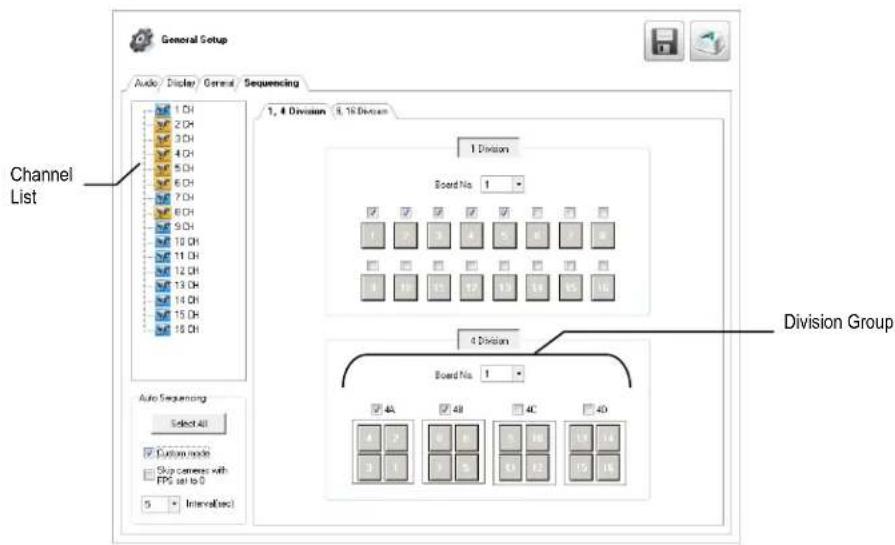
- Select the screen intervals you want to display in each division area.
- Set the Interval time (in seconds). This determines how long each sequence screen will appear on the Live display.
- To save your settings, click Apply.
Note Screen divisions for 9-16 channels will always be visible, even if your recorder has only 8 channels. If you have an 8 channel recorder, channels 9-16 will not be visible on the Live screen.
Use the Alarms/Sensor menu to configure your alarms, sensors, and relays. To access the Alarms/Sensors Setup screen, click Setup on the Live screen, and then click Alarms/Sensor.
Alarms
Intensive on Recording – Enable this function to increase the frame rate and resolution for a camera if an alarm or sensor is activated, or if motion is detected.
Video Loss Alarm – Determine how the recorder will respond if a camera channel loses video. The recorder can beep, the loss can be added to the System Log, or you can activate an external alarm.
Login Failure – Enable this function for the recorder to beep continuously in response to a failed login attempt. Only an authorized login will stop the beeping.
Note If Video Loss Alarm is enabled, do not use Control Output 16 for other purposes. (For 8-channel models, do not use Control Output 8 for other purposes.)
Sensors
Configure Sensors
- Double-click a Sensor Name, and then type an appropriate name for your alarm sensor.
- Double-click Type, and then select the contact type for this alarm, Normally Open (N0), or Normally Closed (NC).
- Double-click Relay, and type the time, in seconds, you want to elapse between the detection of the sensor and when the alarm is activated.
- Click Apply to save your settings.
Activate PTZ Preset
Use this function to activate a PTZ camera to move to a preset position when a sensor event is detected.
- Click Sensor / Preset.
- Select the camera Channel you want to configure.
Note The camera channel must be a PTZ camera. - Select the appropriate Sensor.
- Select the appropriate Preset position for the camera to move to when the selected Sensor is activated.
Note The preset positions must be configured on your camera. Refer to the camera manual for instructions.
- Click Set.
- Select a different Sensor and Preset combination, and then click Set.
- Repeat for all of your desired sensors.
- To delete a Sensor-Preset combination, select the combination in the list, and then click Delete.
- Click OK.
- Click Apply to save your settings.
Hybrid Sensor Setup
This interface is used to link Hard Contact Sensor Inputs from supported Network Devices to the recorder software.
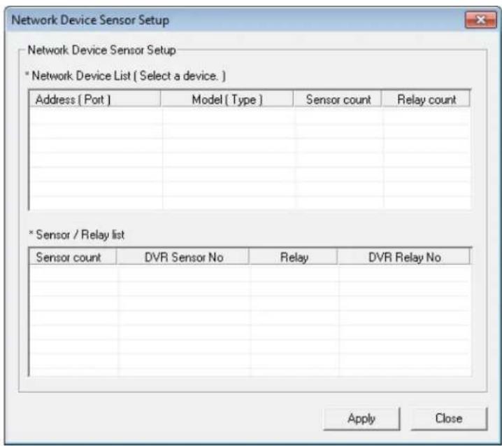
- Click Setup.
- Click Alarms/Sensor, and then click the Sensors tab.
- In the Hybrid Sensor Setup area, click Setup.
- Select a camera from the Network Device List.
- Double-click DVR Relay No, and then select a relay to assign to this camera.
- Click Apply.
- Click Apply again to save your settings.
Relays
- Click Setup.
- Click Alarms/Sensor, and then click the Relays tab.
- Double-click Relay Name for each relay to assign a name.
- Click Apply to save your settings.
The Recording Schedule window allows you to create different recording schedules based on the day, time, and type of recording desired. This window contains the System Restart options. To access the Recording Schedule window, click Setup in the Live screen, and then click Recording Schedule.

Schedule Number – You can create up to 32 separate schedules. Schedules can overlap while still operating independently, creating a very detailed recording schedule.
Special Day Recording Schedule – Customize a schedule for a specific day, such as a holiday or weekend.
Alarm Options – Specify alarm events that will trigger remote alarm monitor software.
Power Off Options – Use this function to specify time frames for turning off and restarting your recorder automatically.
Note Schedules are prioritized in descending numerical order. If there is an overlap, the schedule with the higher priority will override the other schedule. (Example: If there is an overlap in Schedules 1 and 2, Schedule 1 will take priority.)
Default Schedules
These are pre-set schedules. Click Default Schedule 1 or Default Schedule 2 to choose either of the following settings. When you have decided, click Apply to save your settings.
Note Default Schedules are not configured for use with sensors or alarms.
Default Schedule 1
• 8 am to 5 pm, Monday through Friday – All cameras set to continuous recording
- 5 pm to 8 am, Monday through Friday – All cameras set to motion recording
• 24 hours, Saturday and Sunday – All cameras set to motion recording
Default Schedule 2
• All cameras set to motion recording 7 days a week, 24 hours per day.
- Camera 1 is associated with sensor input 1
- Camera 2 is associated with sensor input 2
• Camera 3 associated with sensor input 3
Day of the Week
Day of Week
SUN
MON
TUE
WED
THU
FRI
SAT
Single Selection Mode
Click Single Selection Mode or Multi Selection Mode to switch between modes of scheduling by day of the week.
Single Selection Mode – Set your schedule one day at a time by selecting the appropriate day.
Multi Selection Mode – Set your schedule for multiple days at once by selecting all the days you want to configure.
Creating a Recording Schedule (Example)
The following instructions will help you create a simple schedule for cameras 1 through 4. This is designed as a tool to help you understand how to create a schedule. When you understand the process of creating a schedule, you will want to create one to suit your specific needs.
This example schedule will be as follows:
• MON-FRI (9AM-5:59PM) all 4 cameras will record using MOTION recording.
• MON-FRI (6PM-8:59AM) all 4 cameras will record using CONTINUOUS recording.
• SAT-SUN (12AM-11:59PM) all 4 cameras will record using MOTION recording.
Setting Daytime Motion Detection (Example)
- In the Schedule Number list, select Sch01.
- Click Single Selection Mode to change to Multi Selection Mode.
- Select Mon, Tue, Wed, Thu, and Fri.
- On the Sch01 row, click and drag your mouse to select the hours 9 – 7, and then click Set.
- Click 1 in the Camera section repeatedly, until a green M (motion) appears.
- Repeat for 2 - 4 in the Camera section.
- Click Apply to save.

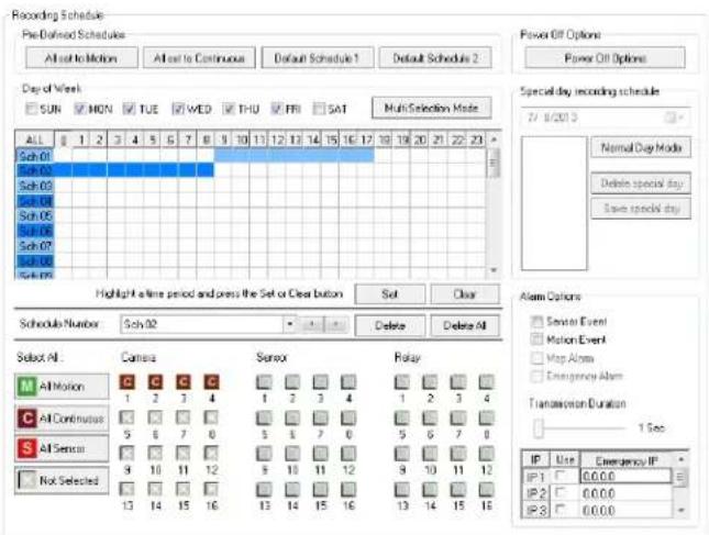
Setting Nighttime Continuous Recording
- In the Schedule Number list, select Sch02.
- On the Sch02 row, click and drag your mouse to select the hours 0 - 8, and then click Set.
- Click 1 in the Camera section repeatedly, until a red C (continuous) appears.
- Repeat for 2 - 4 in the Camera section.
- Click Apply to save.
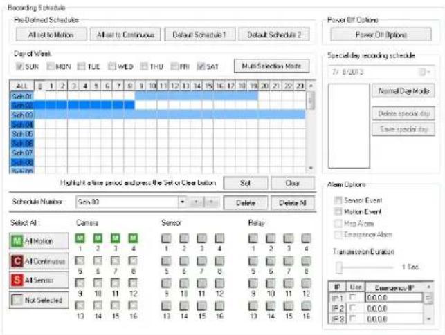
Setting Weekend Motion Recording
- In the Schedule Number list, select Sch03.
- Clear Mon-Fri, and then select Sun and Sat.
- On the Sch03 row, click and drag your mouse to select the entire row, and then click Set.
- Click 1 in the Camera section repeatedly, until a green M (motion) appears.
- Repeat for 2 - 4 in the Camera section.
- Click Apply to save.
Creating a Sensor Schedule (Example)
Sensor inputs can be programmed to instantly trigger recording on one or more camera channels when an alarm event occurs.
Note You must first associate the software sensors with the sensors. See the Hybrid Sensor Setup section of this manual for more detail.
This schedule example will be as follows:
• SUN-SAT (12AM – 11:59 PM) cameras 1 and 2 will be activated by Sensor 3 and Sensor 4.
- Select Sch01 in the Schedule Number list.
- Click the Single Selection Mode button to enable Multi Selection Mode.
- Select Sun, Mon, Tue, Wed, Thu, Fri, and Sat.
- In the Sch01 row, click and drag your mouse to select the entire row.
- Click 1 and 2 in the Camera section repeatedly until a red S (sensor) appears.
- Click 3 and 4 in the Sensor section.
- Click Apply to save.

Special Day Schedule
You can create unique recording schedules for specific days such as holidays or special events.

Creating/Editing a 'Special Day' Schedule
- Click Normal Day Mode to enable the Special Day Mode.
- Set a recording schedule as desired. For instructions, see the Creating a Recording Schedule (Example) and Creating a Sensor Schedule (Example) sections in this chapter.
- Select a day by typing the date or clicking the down arrow to select the date from a calendar.
- Click Save Special Day.
- The special day will appear as a date in the Special Day Schedule. To edit this schedule, select it, and then and repeat steps 1 and 2.
- Click save Special Day. When a confirmation message appears, click OK.
- To continue setting normal schedules, click Special Day Mode to enable Normal Day Mode.
Note When you are making changes in Normal Day Mode, the dates in the Special Day list will appear dimmed. They are still saved, but you cannot access them or make changes unless you are operating in Special Day Mode.
- Click Apply to save your settings.
Deleting a 'Special Day' Schedule
- Click Normal Day Mode to enable the Special Day Mode.
- Select a date from the Special Days list.
- Click Delete Special Day.
Alarm Options
Use the Alarm Options section to configure the alarm output for specific events.
There are two Alarm Options:
- Sensor Event – Trigger an alarm output based on a sensor
• Motion Event – Trigger an alarm output based on motion detection
Motion can be designated as an alarm event. Often motion does not need to be treated as an Alarm event. For example: During work hours, motion that occurs is expected and should not be treated as an alarm. However, after business hours, any motion that occurs could be treated as an alarm.
- In the Display screen, click Setup.
- Click Recording Schedule.
- In the Alarm Options section, select Sensor Event, Motion Event, or both.
-
Once you have selected an Event option, you can select alarm options.
-
Map Alarm –Enable this camera to work the the Map Alarm function of SCS remote monitoring software.
• Emergency Alarm – Send video to a PC running Emergency Agent software. -
Set the Transmission Duration (in seconds) for this alarm.
- Enter up to five Emergency IP of PCs running Emergency Agent software.
Note If you type a URL rather than an IP address in this field, all of the text may not be visible once it is entered. To view the entire URL, hover your mouse pointer over your desired URL.
- Select the appropriate Emergency IP addresses. You can only use one IP address at a time.
- Click Apply to save your settings.
Tip See the Emergency Agent chapter for detailed information on setting up the Emergency Agent software.
Setting a Restart Schedule
The Power Off Options section allows you to define a schedule wherein the recorder automatically restarts according to specified parameters.
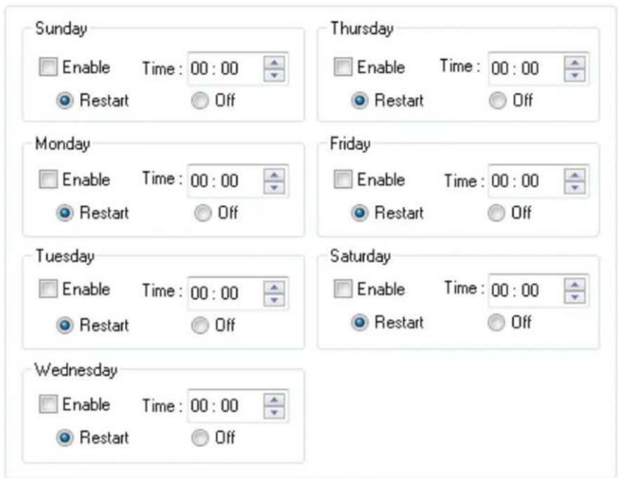

Create System Restart Schedule
- In the Display screen, click Setup.
- Click Recording Schedule.
- Click Power Off Options.
- Select Enable for each day of the week that a restart is desired.
- Specify the time of day to schedule the system restart.
- Select either Restart or Off.
Note If Off is selected, the recorder will shut down at the specified time but not restart. - Click OK.
- Click Apply to save your settings.
Network Setup allows you to adjust network settings such as Ports, and enable Remote Access.
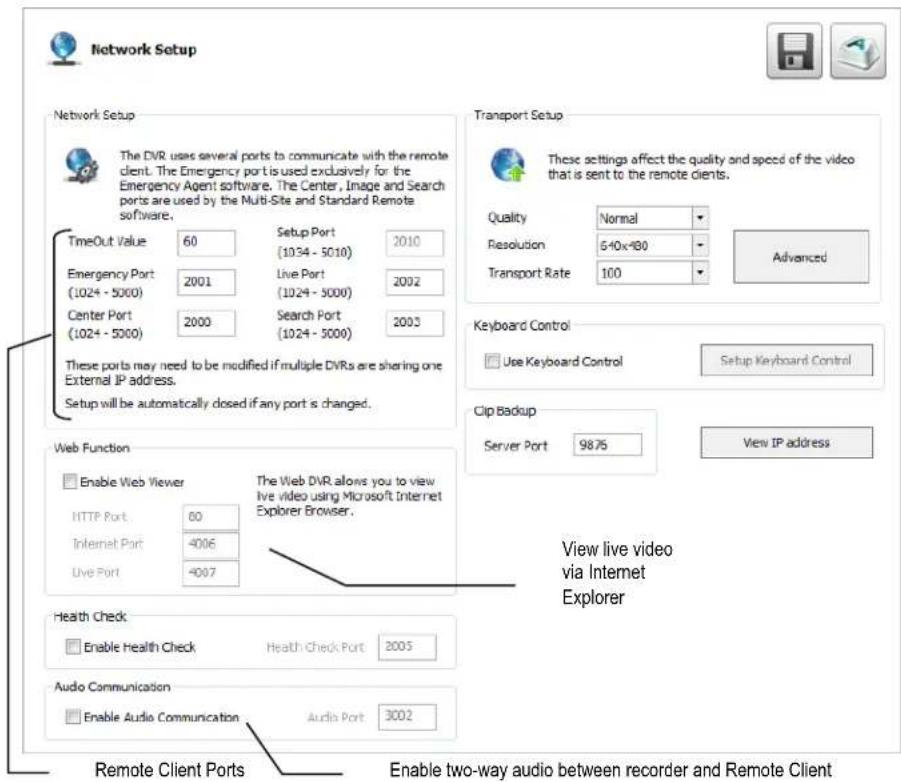
Time Out Value – When attempting to connect to the recorder, if the connection does not succeed during the timeout period (seconds), the connection will be terminated (default: 60).
Emergency Port – Connect with the Alarm Monitor software (default port: 2001).
Center Port – Connect with the Surveillix remote software (Remote, SCS, the Surveillix App). This port must be specified in the remote software to connect to the recorder (default port: 2000).
Setup Port – Enable access to recorder setup when using SCS. This port is locked to the center port, plus 10. (default port: 2010).
Note Center Port 1025 is not available.
Image Port – Transfers the video to the Surveillix remote software (default port: 2002).
Search Port – Transfers search information to the Surveillix remote software (default port: 2003).
Note If connecting to the recorder through a firewall, the above ports must be open to incoming and outgoing traffic.
Health Check Port – Enable SCS to receive information regarding the health of the recorder (default port: 2005).
Audio Port – Enable two-way audio (default port: 3002).
Transport Setup – Use this section to configure the quality and speed of the video sent to remote clients.
Keyboard Control – Enable the recorder to work with a Keyboard Joystick Controller.
Clip Backup – Set the server port for clip backup (default port: 9876).
View IP Address – View the IP address of your recorder for use in remote access applications.
The User Management screen allows the administrator to create, edit, and delete user accounts. Each user account can be assigned different privileges to limit the usage of the recorder system. Users can be given administrator privileges by enabling all rights, however only the true administrator account can access the User Management screen.
Note The Delete User button immediately deletes the user – use cautiously.

Add a New User
- In the Display screen, click Setup.
- Click User Management.
- Click Add User.
- Type a User Name and Password.
- Type the password again in the Confirm Password field.
- Enable the appropriate Permissions.
- Select Camera or Audio channels to hide those channels from the user.
- Assign a User Rank.
Note See the User Rank section of this manual for more information.
-
Click Save.
-
Click Apply to save your settings.
User Rank
The User Ranking structure allows the option to assign a privilege level to users who access the recorder remotely 1-10. (1 is the highest privilege level). For example: Since only one user is allowed to use the PTZ controls at any one time, a user with a rank of 1 will take precedence over a user with a rank of 2 if both are attempting to use PTZ controls.
The User Rank option affects:
Setup Access - The recorder software can only have one user accessing Setup at any given time. A user with a higher rank will kick another user out of the Setup menu.
Note Changes made by a lower ranked user may NOT save when a higher ranked user kicks the lower ranked user out of the Setup menu.
PTZ Control - The recorder software can only have one user using the PTZ controls at any given time. A user with a higher rank will kick another user out of the PTZ controls.
- Log into your recorder as an Administrator.
- In the Display screen, click Setup.
- Click User Management.
- Select a user from the Select User box,
- Set the user's rank using the User Rank list.
- Click Save.
- Click Apply to save your settings.
Changing the Administrator Password
- Select Administrator in the Select User section.
- Type a new Password.
- Type the same password in the Confirm Password field.
- Click Save.
- Click Apply to save your settings.
Default Administrator Password
The default administrator login is:
User: Administrator
Password:
Status Check / Email
Use the Status Check/Email tab in Storage Management to configure settings for status checks and email recipients when status checks require attention. This function can keep you apprised of events detected by your system without requiring you to check the recorder each day.
General
- On the Display screen, click Setup.
- Click Storage Management.
- Click the Status Check/Email tab.
- Click the General tab.
- Select Enable Email Alarm.
- Enter a From Name and email Address.
Note This name and address will appear in the From line of email alert messages.
- Enter the SMTP information for the email account that will be used to send emails from the recorder. Contact your administrator for this information if necessary.
- If using a secondary email account select Use Secondary SMTP and complete the SMTP information.
- Click Test to send a test message to either address.
- Click Apply to save your settings.
Users
- On the Display screen, click Setup.
- Click Storage Management.
- Click the Status Check/Email tab.
- Click the Users tab.
- Select the type of Event to send email on.
- Enter the User and E-mail Address of a desired recipient.
- Click Add.
- Repeat for additional recipients and types of events.
Note A separate email notification for each type of event must be set up for a single recipient to receive notifications for each type of event.
- Click Apply to save your settings.


Storage Check
- Set up the General and Users tabs first.
- Click the Storage Check tab.
- Select Enable.
- Define the frequency of storage checks (in minutes).
- Select an additional Alert Option if desired: Beep or Popup Message.
- Add a Comment that will be seen in the email message if desired.
- Click Apply to save your settings.

Recording Data Check
- Set up the General and Users tabs first.
- Click the Recording Data Check tab.
- Select Enable.
- Define the frequency of data checks (in hours).
- Select the Action Method: Popup Message Alert, Beep Alert, or Email Alert.
- Add a Comment that will be seen in the email message if desired.
- Click Apply to save your settings.

SMART Alert
- Set up the General and Users tabs first.
- Click the SMART Alert tab.
- Select Enable.
- Define the frequency of SMART status checks (in hours).
- Select the type of SMART event to trigger an action.
- If selecting for temperature checks, define the maximum HDD temperature.
Note Surveillix recommends a temperature threshold of 150° F ( 65° C) if you choose to use this function.
- Select an Action Method: Beep Alert, Popup Message Alert, or Email Alert.
- Add a Comment that will be seen in the email message if desired.
- Click Apply to save your settings.
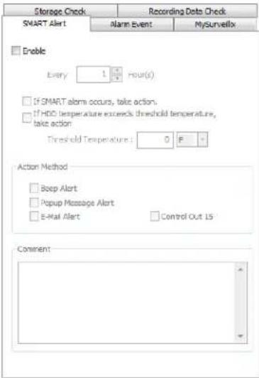
Alarm Event
- Set up the General and Users tabs first.
- Click the Alarm Event tab.
- Select Enable.
- Define the frequency to send email alerts (in minutes).
- Select the Event Type: Motion, Sensor, No Signal (video loss).
- Select With Detail Info to receive a still image attachment of the associated camera in the email message.
- Max Count defines the number of message that will contain detailed data within the frequency time frame.
- Add a Comment that will be seen in the email message if desired.
- Click Apply to save your settings.
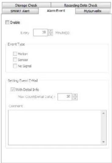
MySurveillix
- Set up the General and Users tabs first.
- Click the MySurveillix tab.
- Select Use MySurveillix.
- Enter a numeric Security Code if desired (this is an additional security measure to prevent unauthorized users from adding the recorder to their MySurveillix account).
- Define the Send Time to designate the time the recorder will send updates to MySurveillix.
- Select Send notification to MySurveillix on alarm events if you want the recorder to report alarm events to MySurveillix.
- Type a new MAC Address if necessary.
- To set a custom time to send updates to MySurveillix, select Custom Day/Night, and then select your desired Day and Night times.
- To send updates to a custom URL, select Send to Custom URL, and then type in the URL.
- Click Apply to save your settings.

SMART Information
The SMART Information tab displays Hard Drive information.

Data Management
The Data Management tab displays the partition scheme and health status of the Hard Disk Drives in the recorder. Use this tab to troubleshoot a recorder, or verify the amount of Hard Drive storage installed. This function is native to the Windows operating system. For more information about Disk Management, consult a Windows 7 manual.
![Storage Management Status Check/Email / Smart Information / Data Management HDD Property Use Drive Type Total Size.Free Space Etc None Backup [D:] Local Drive 2.69 TB 2.69 TB Record CVR [E:] Local Drive 2.72 TB 1.02 TB None [+] Removable Drive 0.00 B 0.00 B File Management View File Info Storage Man…](/content/2026/06/1148326/images/768441b8926708d403d2110ea35775f898c655da6c18a62d474d00802fcf20ff.jpg)
Note Double-click a drive in the Use column to assign the drive a specific function (Record, Backup, or None). This function is for use in software-only applications, and is not needed when using this software with a recorder.
File Management
- Click View File Info to view all file information.
- To export file info, click Export, and then browse to your desired location.
- Click Save.
- Click Close.
Storage Management
- Click Disk Management to access the Disk Management function of the Windows operating system.
- To view this window, close the Setup window, and then click Exit.
- Select Restart in Windows mode, and then click OK.
- For instructions regarding Windows Disk Management, please refer to a Windows 7 manual.
System Information
The Log Management window provides you the options to overwrite log files or schedule log deletion.
Basic Information
The Information display allows users to define the site code necessary for connecting to remote software, save comments relative to the recorder, store tech support and contact number information, and see the currently running server software version.
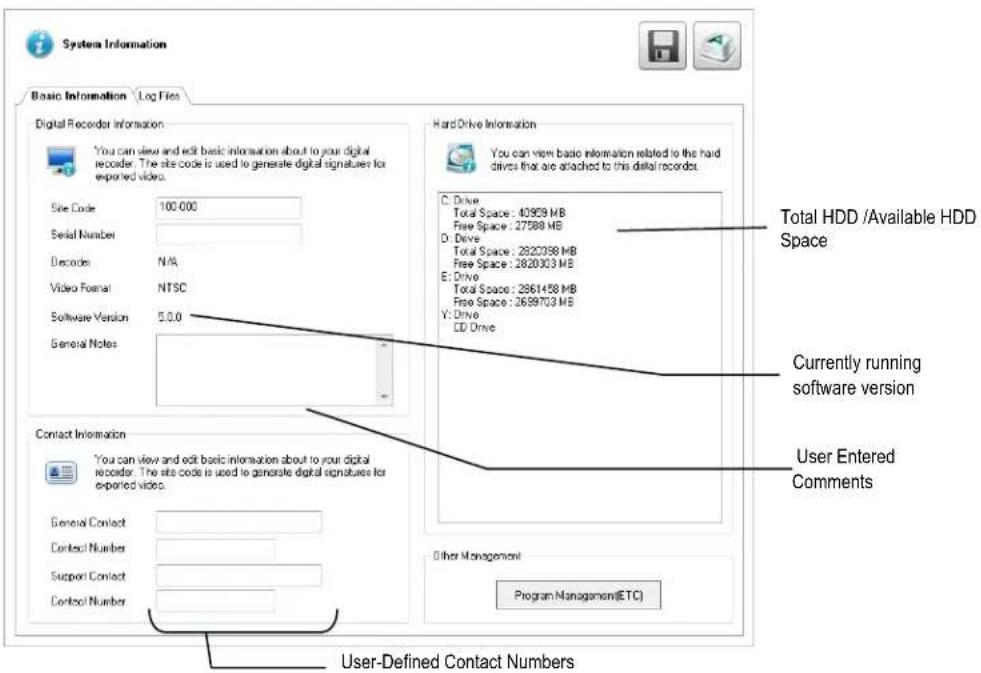
Site Code – A user-specified unique identification name used by other recorder software to identify the recorder. (Remote, Emergency Agent, SCS, Digital Signature Verifier)
Contact Information – Attach contact information as a digital signature to exported video.
Other Management – Click Program Management to access External Program Management.
Program Management
Seng up DDNS
Dynamic Domain Name System (DDNS) is a service that provides a static address to simplify remote connection to the recorder. This service is most useful for installations where the WAN (public) IP address is dynamic (changes from time to time). Most public IP addresses are dynamic unless a static address has been specifically ordered from the internet service provider.
Enable DDNS
To enable this functionality of the recorder, follow the steps below:
- Click Setup on the Display screen and log in as Administrator if prompted.
- Click Administrative.
- Click Program Management (ETC) and enter the Administrator password when prompted.
- Click Show (to the right of Dynamic DNS Configuration).
| Program Manager(ETC) | |||||||
| Index | File name | Desc | Status | Start | Stop | Show | Hide |
| 1 | DDNS User Infor... | Dynamic DNS Configuration | NOT RUN | Show | |||
| 2 | Information Col... | Collects DVR Information and se... | NOT RUN | Show | |||
| 3 | Perfmon.exe | Opens Performance monitor. | NOT RUN | Show | |||
5.
- Select Enable DDNS.
- Enter the User Name, Password, and Hostname specified on the DDNS document shipped with your recorder.
- Click OK, and then close the Program Manager window.
Note Ensure the recorder has an IP address by setting it statically. The Network settings may need to be changed. If you are not sure of the correct values, contact the individual or department responsible for network administration at the site.
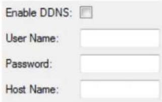
Set the IP Address
The IP address of the recorder is set in Windows; to set the IP address follow the steps below:
- On the Display screen, click Exit and choose Restart in Windows Mode.
- Right-click My Network Places and click Properties.
-
On the General tab, click Internet Protocol (TCP/IP) and then click Properties.
-
Select Use the following IP address.
-
Enter values for the IP Address, Subnet Mask, and Default Gateway (these may be specified by the department responsible for network administration).
a) IP Address: The first three sets of numbers should match the router's local IP address and the last set should be a unique number between 1-254.
b) Subnet Mask: This should match the router's setting (commonly 255.255.255.0 for 192.X addresses and 255.0.0.0 for 10.X addresses).
c) Default Gateway: This is the router's internal IP address. Once DDNS is configured, the router the recorder connects to will need to have port forwarding configured.
For further instruction on this process, visit http://www.portforeward.com/english/routers/port_forwarding/outerindex.htm
Once DDNS and port forwarding have been configured, the recorder will be accessible from any remote site by entering the HOSTNAME into the address bar of Internet Explorer or the IP Address field in remote software.
Informaon Collecon
The Information Collector is a log-collecting utility gathers all system logs and prompts to be exported. This troubleshooting tool is to be used when working with technical support to diagnose a problem with your recorder.
Performance Monitor
The Performance Monitor (perfmon.exe) brings the Windows Utility Performance Monitor to the foreground. This troubleshooting tool is to be used when working with technical support to diagnose a problem with your recorder.
Log Files
Use the Log File tab to view logs for system, event, alarm, and drive check statuses by date. You can also export logs, and manage how the log files are stored.
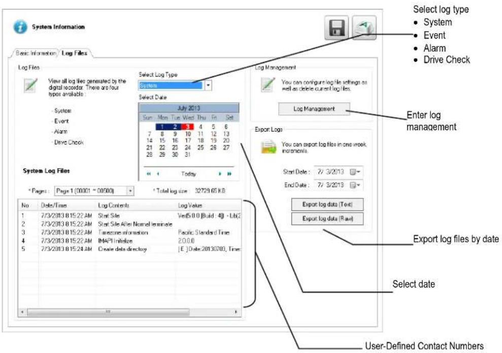
Viewing Log Files
- Click Select Log Type, and then select the type of log you want to see (System, Event, Alarm, or Drive Check).
- Use the Calendar to select the date you want to review.
- Scroll through the System Log Files list to view your files.
Exporting Log Files
- Select a Start Date and an End Date.
- Click Export Log Data (Text), or Export Log Data (Raw), depending on your needs.
- Browse to the location you want to save your files, and then click OK.
Set Up Log Management Options
- In the Display screen, click Setup.
- Click System Information, and then click the Log Files tab.
- Click Log Management.
- Select Log File Overwrite Option to enable.
- Select Overwrite or Do Not Overwrite.
- If Overwrite is selected:
a) Enter a maximum Log File Size.
b) Choose a number of days to keep logs (Delete Log File Older Than).
Note Log files can also be manually deleted. Simply select the log you want to delete on the bottom portion of the window, then click Delete All.
- Click OK to save the settings and close the window.
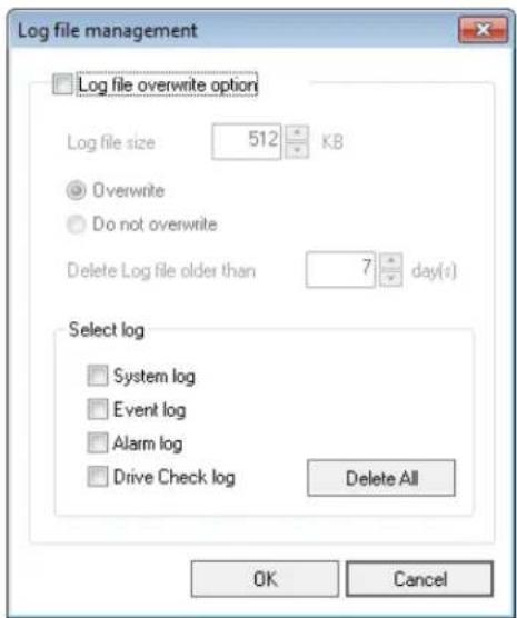
The Instant Recording feature allows users to manually initiate recording on a specific camera, overriding the current schedule. When Instant Recording is activated the recorder flags the clip as an event so Instant Recording instances can be found using the Index Search Instant Recording can be used, for example, when a suspicious object or person is detected and you want to flag that section of video for easy retrieval at a later date.
Activate Instant Recording
- On the Display screen, right-click the camera on which to enable instant recording and choose Instant Recording (or double right-click). An INSTANT label will be placed on the upper right corner of the video.
- To turn the Instant Recording option off, right-click the camera and choose Instant Recording (or double right-click).
Searching 'Instant Recorded' Video
- On the Display screen, click Search.
- Click Index.
- Select the Instant Recording option, and then click OK. See the Search chapter for more information.
SEARCH
This chapter includes the following information:
- Search Overview
- Basic Search
- Printing an Image
• Daylight Savings Time - Index Search
- Preview Search
- Status Search
- Object Search
- Motion Search
- Search in Live
The recorder has several options that allow the user to easily find recorded video. From Motion/Sensor indexing to calendar views highlighting days with recorded video; the recorder is equipped to help you quickly find a specific video or event. This chapter describes how to use the Search features.

Note Audio Channel buttons are only viewable when one camera is selected.
Play Controls
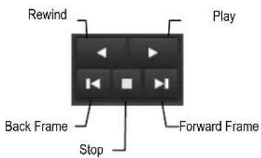
| Back Frame | Moves video back one frame |
| Rewind | Rewinds video |
| Stop | Stops video playback |
| Play | Plays video |
| Forward Frame | Moves video forward one frame |
Adjust the Brightness of an Image
Select an image to adjust by double-clicking on the desired image. Multiple images cannot be adjusted at one time.
- Move the Bright slide bar to the right or left to adjust the brightness.
- Reset the Brightness by moving the slider back to the center of the bar.
Zooming in on an Image
- Select an image to adjust by double-clicking on the desired image. Multiple images cannot be adjusted at one time.
- Move the Zoom slide bar to the right or left to zoom in or out of an image.
- Reset the Zoom by moving the slider back to its original position on the bar.
Zooming in on a Portion of an Image
- Right-click the area of interest on the image and select Zoom. - or - Double-right-click the image.
- Repeat to zoom in further.
- Continue clicking the right mouse button and the image zoom will cycle back to the original size.
Open Video from a Saved Location
Previously saved video clips or backup files can be searched for content. Find file by date and time or by name.
- Click Open File to search for the saved file.
- Select a file from the list of saved clips and backup files or search by start hour.
- Click OK to open the saved file.
Sync
The Time Sync option synchronizes a single channel of video to playback in real time. Ordinarily the video may playback slower or faster depending on several factors, including how many IPS recorded and number of cameras playing at the same time.
- Select a single image to synchronize by double-clicking on an image.
- Click Sync. The video will now playback in real time.
Clean Image
The recorder is capable of recording video using one of three different resolutions. When using the 720 x 480 resolution, two fields are mixed. Because of the timing gap between the two fields, according to the standardized image rules, after image might occur to high speed moving images. The recorder allows the user to remove this by clicking Clean Image.
PERFORMING A BASIC SEARCH
There are several different types of searches that can be performed on the recorder. The most basic involves selecting the date, time, camera, and clicking play.
- Click Select Date.
- Select a date on the calendar.
- Select a time by clicking the up and down arrows to the right of the time display.
- Click OK.
- Select a Camera channel or Channel View.
- Click Play. Video can be played forward, backward, or frame-by-frame.
PRINTING AN IMAGE
- Search video to locate a video frame you want to print.
Note Only one camera can be selected at a time for this function to work.
- Click Print. A Print Options window will appear. Depending on your printer, there may be several printing options available. Refer to your printer manual for more information.
- Select your desired Zoom, Scale, and layout options.
- Select View Title to include camera and recorder information on the printed image.
- Click Print to print the selected image.
Note If no printer is installed, your recorder will freeze. If this occurs, restart your recorder, and then add a printer.
The recorder automatically adjusts for Daylight Saving Time changes. When the hour "jumps forward" no video is lost because an hour is skipped. However when the hour "falls back" there is a duplicated hour that under normal circumstances would be recorded over. The recorder actually records both hours and allows the user to select which hour to play if the need arises.
To access the 'lost hour':
- On the Search screen, click Select Date.
- Select the date when Daylight Saving time 'lost' an hour. The Daylight Saving option appears.
- To play back the 'lost hour', select Daylight Saving, select 02:00 (2AM) for the time.
- Click OK to confirm the date and begin playing the video using standard search features.

Your recorder can export single images in a JPG Image file format and save video clips in an AVI format. JPG and AVI file formats are the most commonly used graphical formats today. Virtually every computer offers some type of support for these file formats which make them the most ideal formats to use. Only one camera can be selected at a time for this function to work.
Image Images can be exported in JPG, PNG, or BMP formats. The JPG format is optimized for compressing full-color or grayscale photographic images (uses lossy compression, and will create a small file size). The PNG format is designed to maintain more quality while still compressing full-color or grayscale photographic images (uses a lossless compression, and will create a medium file size). The BMP format can be used for full-color or grayscale photographic images (uses little, or no compression, and will create a large file size). Use any of these options to export a single image or frame.
AVI AVI image data can be stored uncompressed, but it is typically compressed using a Windows-supplied or third party compression and decompression module called a codec. AVI is used to export a video clip.

- Locate your desired video or frame using the Search screen.
Note To save a JPG or AVI file, you can only search one camera channel at a time.
-
Click Save.
-
Select the Export Type: Image File (JPG, PNG, or BMP) or AVI File.
Image File
c) Select Quality (50-100). When size is not an issue, set the quality to 100.
AVI File
d) Enter the duration (in seconds) to save. Although suggestions are provided, a selection between 1 and 3600 can be entered manually.
e) Select a Compression Codec. Each codec provides different levels of quality, compatibility and file-size.
f) Select Quality - 50 - 100. When file size is not an issue, set quality to 100.
-
The digital signature is already entered, but can be changed if required.
-
Click Export.
-
Select a location to save the file, enter a name for the file, and click Save.
a. Click Cancel to exit the window without exporting file.
Bookmarks
Use bookmarks to mark a video clip during a search. Export bookmarked data using the Clip Backup feature.
- Locate your desired video using the Search screen.
- Stop playback at the beginning of the desired clip.
- Right-click the video and select BookMark Start.
- Click the play button to continue playback.
- Stop playback at the end of the desired clip.
- Right-click the video at the desired end point and select Bookmark End.
- Type a name to identify the bookmark in the Title field.
- Type a memo or notes in the More Information box.
- You may also select additional channels to include video at different locations recorded at the same time.
- Click Create.
Modify Bookmarks
You can modify a previously created bookmark to change the start or end time of the clip, add additional comments, change the title, or add additional cameras.
- In the Search screen, click Bookmark.
- On the calendar, select the date the desired bookmarks were created.
- Select the desired bookmark from the list.
- Make your desired change.
- Click Modify.
- Click OK, and then click OK again.
- When the modification is complete, close the window.
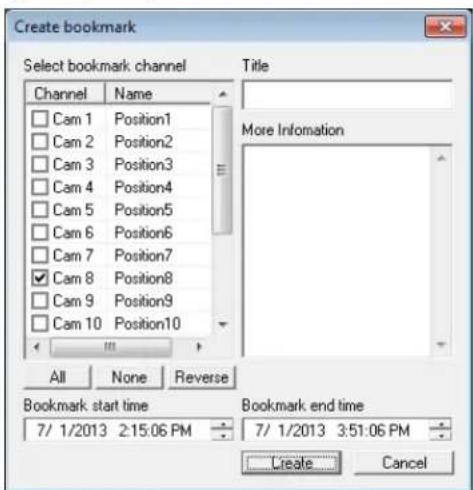
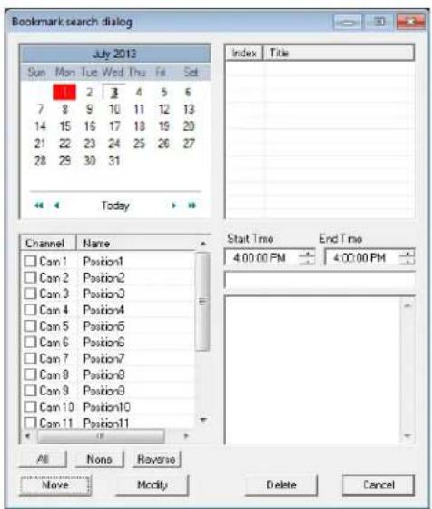
Clip Backup
Within the Save option, Clip Backup can also be utilized to backup a single camera or multiple channels. The Clip Backup option gives you the ability to choose a backup time frame, choose a specific camera or cameras, add memos, and even include the Backup Viewer if needed.
- In the Search screen, click Save.
- Select the drive from the file tree to save data to (Hard disk drive, removable drive (USB), CD/DVD drive).
- Select your desired cameras from the list.
- Define the Start and End time and date that you wanted to backup.
- Select Include Viewer to include a copy of the proprietary Backup Viewer Software to view the clip on virtually any Windows workstation.
- Click Add Memo to include additional information.
- Click Backup to start the backup.
![Save / Clip Backup Save Clip Backup Drive: My computer D: [Backup 30.00.02 MB Free] Y: [6.0045716 MB Free] channel selection Channel Name backup start 5/ 7/2014 7.49.41 AM backup end 5/ 7/2014 7.49.46 AM Include Viewer Add Memo Use bookmark data Cam 1 Position1 Cam 2 10.89.90.80 Cam 3 169.254.79.29…](/content/2026/06/1148326/images/efe416f853cd82033e063dc356de0dfcd8ac13c88e93ad8e1e47764969b6c0d7.jpg)
Single Clip Backup Using Bookmark Data
- From the Search screen, click Save.
- Select the drive from the file tree to save data to. (Hard disk drive, removable drive, CD/DVD drive).
- Click Use Bookmark Data.
- On the calendar, select the date the desired bookmarks were created.
- Select the desired bookmark from the list.
Note To include multiple bookmarks in a clip backup, select the Multi Backup check box before selecting the desired bookmarks.
-
Select Include to include a copy of the proprietary Backup Viewer software to view the clip on virtually any Windows workstation.
-
Click Backup to start the backup.

Using the Index Search can greatly decrease the amount of time spent searching through saved video. The Index Search allows you to perform a search based on criteria such as Sensor, Motion and Instant Record events.
Performing an Index Search
- Click Calendar on the Search screen to select the date to search.
- Click Index.
- Select the cameras and sensors to include in the search.
- Select the Select Time check box to define a specific period.
- Select an event type to search in the Select Sort Option section (Sensor, Motion, Instant Record), or select the All Event Types option.
- Click OK. There may be a delay while results are returned. Results will be displayed in a column on the right side of the screen – Each line represents a segment of video. If no results are found, "NO IMAGE FOUND" will appear in the column.
- Once the results are displayed, double-click any result to play the associated video.
- Once your desired image is found, apply it to the Main Search by clicking Close at the bottom of the results column.
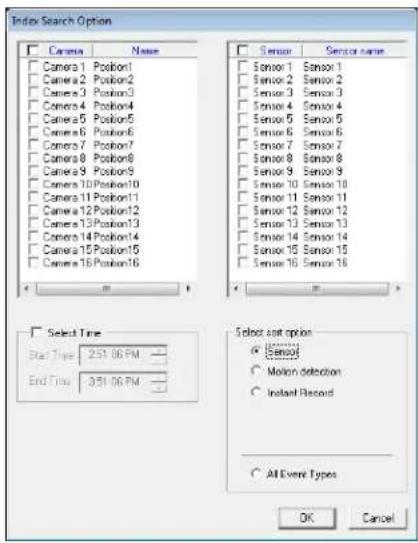
Index Search Results Display
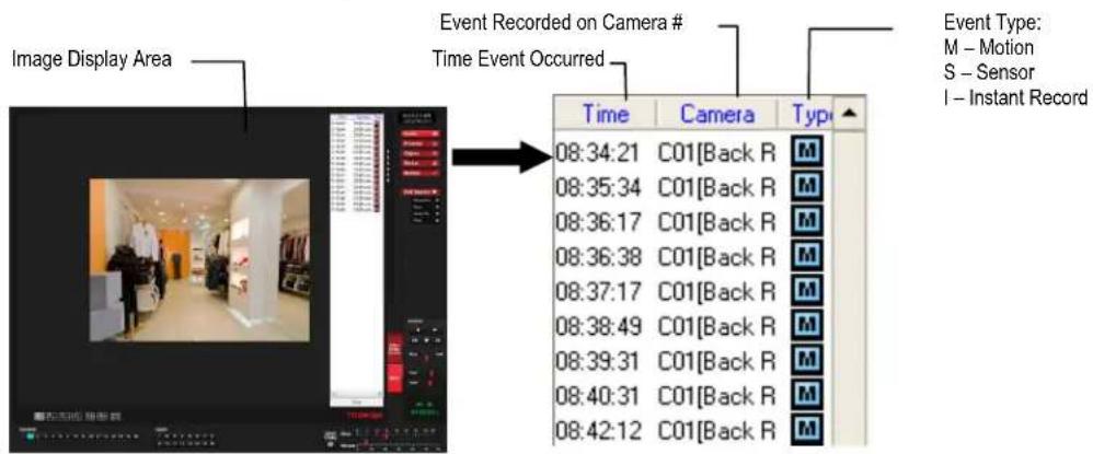
Note Index Search will present each frame recorded during an Alarm or Motion event as an individual event.
Preview Search can be used in a number of circumstances to quickly find an exact moment where an event, such as a theft, occurred. The Preview Search gives a 24 Hour visual overview of a single camera by separating a 24 hour period (1 day) into 24 images, one image for each hour of the day. The search can then be further narrowed down into ten minute increments and one minute increments by selecting one of the images displayed.
These example images show how the Preview Search functions.
The first screen that appears has 24 images displayed. Each image represents the first second of recorded video in each hour. If there is no image recorded during that period then nothing will be displayed.
When an hour is selected (by double clicking on the image), a new screen appears with 6 images. Each of these images represents the first second of video for a 10 minute segment of video within the selected hour.
Once a 10 minute segment is selected (by double-clicking on the image) the final screen appears which breaks down that 10 minute segment into 1 minute increments (10 images).
![graph TD A["1 Day (24 Hours) Total\n1 Hour Increments"] --> B["1 Day: 1 hour + 2 hour"] B --> C["6: 1 hour + 7: 3: 4: 5: 10: 16: 17: 18: 19: 20: 21: 22: 23: 24:"] C --> D["11: 1 hour + 12: 13: 14: 15: 6: 7: 8: 9: 10: 16: 17: 18: 19: 20: 21: 22: 23: 24:"] D --> E["16: 1 hour + 17: 18: 19: 20: 6: 7: 8…](/content/2026/06/1148326/images/fbaccf11842d913cbad83d85d51d9bbe98ba403090f6bd5c396a19090c7d5351.jpg)
Performing a Preview Search
- Select a single camera channel.
- Click Preview. 24 images display. If there is no recorded video during a portion of the day, "No Image" will be displayed where the image would be.
- Refine the search by double-clicking on an image to select it. 6 images display. If needed, return to the previous 24-image view by double-right-clicking on any image.
- Refine the search by double-clicking on an image to select it. 10 images display. If needed, return to the previous 6-image view by double-right-clicking on any image.
- Double-click an image to select the 1-minute segment of video to play. A single image displays. If needed, return to the previous 10-image view by double-right-clicking on the image.
- Use the Play controls to play the video of the selected segment.
- To exit out of the Preview search with the current image still selected, click Preview again.
STATUS SEARCH
The Status Search option displays video in graph format.

Performing a Status Search
- Click Status on the Search screen.
- Click the calendar icon to select a day.
- Click on an area of the blue recording block. Only one camera can be displayed at a time.
Note Each recording block represents a 10 minute time frame.
- Recorded video from the corresponding camera and time block will display above.
- Use the mouse or arrow buttons to move through recording blocks and view video.
- To exit Status search with the current image still selected, click Status again.
Object Search is a powerful search utility that is used to search a region on the video for any motion changes. Results are neatly displayed and can be viewed quickly.
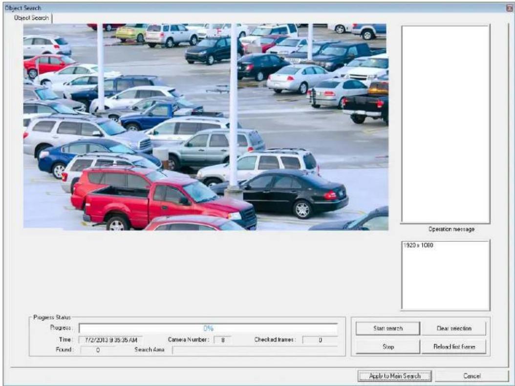
Performing an Object Search
- Select a single camera channel.
- Click Object.
- Click and drag the mouse on the video display to define a motion region area. Resize by pulling on the small square boxes located on the outer perimeter of the area.
- Click Start Search, the Object Search Filter Information window will open.
- Select an End date/time.
- Adjust the sensitivity if necessary.
- Click OK.
- Select a motion event from the search results list displayed on the right
- Click Apply to Main Search to display the selected image in the main Search screen and to use play controls.
- To start a new object search using the original image, click Reload First Frame.
- To exit Object search without selecting an image, click Cancel.

The Motion Search provides a dynamic display of the levels of motion in recorded video. Adjust the level of motion to only play clips of video at or above that level.
To enable motion data to be saved for Motion search, ensure that you select the following settings:
- On the Motion setup page under Motion Regions, select Detect Detail Motion Area.
- On the General setup page under Display, select Motion Detect on Continuous Recording.
Note Motion Search is only available for newly recorded video; it is not compatible with video recorded prior to installing version 3.6.
![Camera Information C03[Position3] 12:02 35 PM 5/4/2013 Motion Tolerance Level Level : 48% Timeline Control 24 Hours 12:00 AM 8:00 AM 4:00 PM Tuesday, June 04, 2013 Timeline](/content/2026/06/1148326/images/d1265d91979d80386b5fb74f7ad81cd413f22f57af177b03b5734fb71d5abbee.jpg)
Performing a Motion Search
- Select a single camera channel.
- Click Motion.
- Click the calendar icon to select a day.
- Adjust the motion level line.
- Adjust the timeline display settings.
- Click the Play button to start playback.
- To exit Motion search with the current image still selected, click Motion again.
Tip You can drag the blue line on the Timeline or motion level box to adjust the time.
AUDIO PLAYBACK
Audio is played back at 48,000Hz.
To play audio with the video:
- Select a single camera channel. The audio options will be displayed in the lower right.
- Select a single audio channel to play. When an audio channel is selected, Sync will be automatically selected.
- Click Play.
The Search in Live feature allows users to review events immediately while monitoring live video. Pause, rewind, and resume live video within seconds of an alarm event or suspicious activity.

- Move the mouse cursor over the desired live video display on the Live Display screen.
- Right-click and choose Search In Live (or click the scroll wheel on the mouse).
- The Search In Live controls will display at the bottom of the image.
- Use the controls to pause, rewind, move frame-by-frame or resume playing as desired.

- To exit Search in Live, click the scroll wheel on the mouse in the camera area you have been searching.
PAN / TILT / ZOOM
This chapter includes the following information:
- Overview
- Setting up the PTZ
- Creating and Viewing a Preset Position
- Creating and Viewing a Preset Pattern
The PTZ controls within the recorder allow you to control PTZ cameras without accessing them directly. This can increase the usefulness of your recorded video. Using the PTZ controls, you can create custom preset configurations that can continuously sweep across large areas.
Note These instructions are for use with Analog PTZ cameras only. For IP PTZ cameras, please refer to the PTZ Camera Setup section of this manual.
Note PTZ setup and control is only available for supported video encoders with a PTZ RS-485 pass-through.
Basic PTZ Configuration
- On the Live screen, click Setup, and then click PTZ Setup.
- Select a PTZ-enabled camera from the Select Channel list.
- Select Enable Pan Tilt Connection.
- Click Select Protocol and select the appropriate protocol for your PTZ camera. For information on the protocol used by your PTZ camera, refer to your camera manual.
- Set the appropriate Port, Baud Rate, Parity, Data Bits, and Stop Bits. These settings must match those of your PTZ camera. For more information, refer to your camera manual.
- Click Apply to save your settings.
Select Channel
[Camera 01]: Position 1

Connection Information

Enable and configure Pan Tilt Zoom controls for the selected camera.

Enable Pan Tilt Connection

General
The General tab in PTZ Setup allows you to reverse PTZ direction function if necessary, enable the use of Onscreen Compass for PTZ control, set the speed for your camera, and set the camera ID.

PTZ Address Settings
- Some protocols support software address settings.
• The RX-Addresses and ID settings are compatible with a particular line of receivers that support 2 ID addresses. - The PT Driver Address is associated with the PTZ ID address set on the camera. The addresses must match for the recorder to communicate with the proper PTZ camera. This is especially important when a large number of PTZ cameras are connected to the recorder.
Note To select a PT Driver Address of 129-256, manually enter the ID in the box.
PTZ Presets/Tours
A Preset Position is a user-defined location where the camera can be pointed, zoomed-in, and focused. Preset positions can be defined and labeled if the camera supports this. Configure these functions using the Presets/Tours tab.
Creating a Preset
- In the Live view, click Setup, and then click PTZ Setup.
- Select the PTZ camera you want to configure in the Select Channel list.
- Click the Presets/Tours tab.
- Move the selected camera to your desired position.
- In the Preset section, select a Preset # (1-10), and then click Set.
Note Preset positions can be created using the advanced buttons on the PTZ graphical controller.
Viewing a Preset
- Double-click on a PTZ camera channel on the Display screen.
- Click Pan/Tilt to enable the Graphical PTZ Controller.
- Click your desired Preset number on the controller.
ACCESSING PTZ MENUS
Some protocols support the ability to access the Internal PTZ Onscreen menu.
Since every PTZ camera is different, the function of these options can vary slightly.
The Surveillix recorder provides an easy way to access the camera options. For explanations of what those options are, please refer to the user manual for the camera.
Note Use the arrow buttons on the PTZ controller to move through the PTZ menu options and/or highlight options.
CONTROLLING A PTZ CAMERA
Surveillix recorders provide control for a PAN/TILT/ZOOM camera in two different ways.
• Use the Graphical PTZ Controller that appears when the PTZ button is clicked on the Display screen.
• Use the mouse to control the camera directly from the live video display (On-Screen Compass)
Using the Graphical PTZ Controller
- In the Display screen, click Pan/Tilt.
- Click the viewing area of the PTZ camera you want to control.
- Use the Arrow buttons to control the direction of the PTZ camera.
- To select a new camera, click the video display of a different camera on the Display screen display.
Note Eight directions are available only for select cameras. Only four of the PTZ Control buttons work for all protocols (UP, DOWN, LEFT, RIGHT).
Note The Advanced menu panel on the graphical PTZ controller can be used to set PTZ preset positions (on supported cameras), as well as move to presets up to 254.
- To exit the Graphical PTZ Controller, click Pan/Tilt again.

Using the On-Screen Compass
- On the Live screen, click Setup.
- Click PTZ Setup.
- Select the Camera Channel of the PTZ camera you want to enable Onscreen Compass control for.
- In the General tab, select Onscreen Compass.
- Click Apply.
- Close the Setup window to return to the Live screen.
- Click Pan Tilt.
- Control the PTZ camera by clicking and dragging the mouse on the screen in the desired direction.
Note A green line will appear to show the direction in which the PTZ camera will move. The shorter the line, the less the PTZ will move. The longer the line, the more the PTZ will travel in the specified direction.
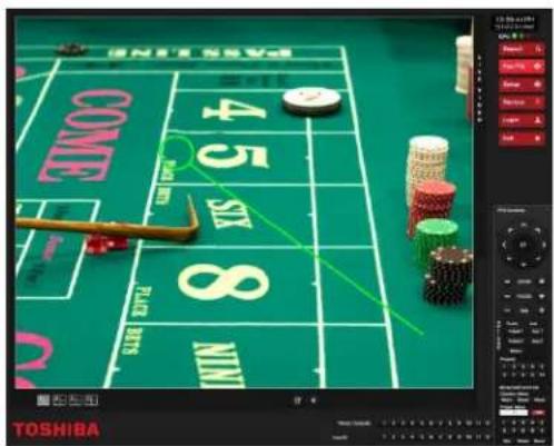
Understanding Tours
Tour Method – Select a Tour to program.
Setting: Start Pos / End Pos – Define a Mimic Tour. The Start Position button begins the recording process. The Stop Position ends it.
Privacy Zone – Define an area that the camera will not view to create a Privacy Zone.
Pan Swing / Tilt Swing – This option enables the Horizontal (Pan) or Vertical (Tilt) Guard Tours.
Travel Speed – The speed between one Preset Position to the next
Dwell Time – The length of time (in seconds) that a PTZ Tour displays a Preset Position
Run / Stop – Runs the selected Pan or Tilt tour

PTZ Tour Schedule

- In the Live screen, click Setup, and then click PTZ Setup.
- Select the PTZ camera you want to configure from the Select Channel list.
- Click Tour Schedule to open the PTZ Tour Schedule window.
- Click and drag the pointer to select blocks of time (hours 0-24) on the desired days of the week.
- Click Select.
- When finished, click OK to save changes and close the window.
This chapter includes the following information:
- Overview
- Saving Video to a DVD
• Saving Video from a Single Camera
• Scheduling Regular Video Backup
The Backup Center allows you to back up recorded video data from multiple dates and times to one or more locations including the DVD-RW drive, Network Storage Locations, and External Hard Drives.
The recorder can easily backup important video data to an internal or external media location. The most commonly used forms of this are CD-Rs, DVD-Rs, External USB or FireWire Hard Drives, and Network Drives. Every recorder comes equipped with a DVD-RW drive, USB port, and Network Adapter.
The recorder is capable of performing a backup to multiple CD/DVDs when the file sizes exceed the capacity of a single disk. You may also specify multiple locations for backup as well as the order they are recorded to.
The recorder backs up video data using a proprietary compression format that can only be read by the Surveillix Backup Viewer software. This ensures the integrity of the data.
Throughout the backup process the recorder will continue recording data without interruption. This is the result of the tremendous multiplexing power of the recorder, which allows it to perform virtually all functions without disrupting the recording process.
Nero® Express
The recorder uses Windows®7® Embedded running Nero® Express 9.0 to write data to the DVD-RW Drive. This solution allows the recorder software to read and write data to the DVD-RW Drive without formatting the disk first.

Caution
Although many features are available within Nero, it is highly recommended that you do NOT use any features other than those necessary for the standard backup of video data as outlined in this section, loss of information or software instability may result.
General Backup Overview
The General Backup screen is used for performing bulk backup of video recorded by all cameras for a selected period, or periods, to a specified storage location.

Hour / Minutes
Recording data displays in hourly (24 vertical columns) and 10-minute (6 horizontal rows) segments. Green cells indicate time with recorded video. Red cells indicate time selected for backup.
Backup Status
Displays the size of all video currently selected for backup, the available size of the media currently selected for backup to, and the dates and times of video currently selected for backup.
Fixed HDD
Display all Hard Drives.
Note Disks must be named Backup in order to be recognized. If you do not see your desired drive, exit to Windows and re-name your drive.
Performing a General Backup
- In the Display screen, click Backup.
- Select the date or dates to back up using the calendar. Dates highlighted in blue contain recorded data.
- Select the blocks of time to back up using the Hour/Minute grid. Blocks of time with recorded video are highlighted in green. Blocks of time selected for backup are highlighted in red.
- Select the backup drive or drives in the Select Backup Media section, or click Network Drive, or Browse. When selecting the CD-ROM drive you must specify the number of CDs to use for backup.
- Click Backup Order to set the backup order.
- Select the Include Viewer check box to include the Backup Viewer Application.
- Click Start Backup to begin the backup process. A progress bar will display in the lower right corner of the Display screen.
Clip Backup Overview
The Clip Screen is used for backing up video recorded by individual cameras for a selected period of time to a specified storage location.
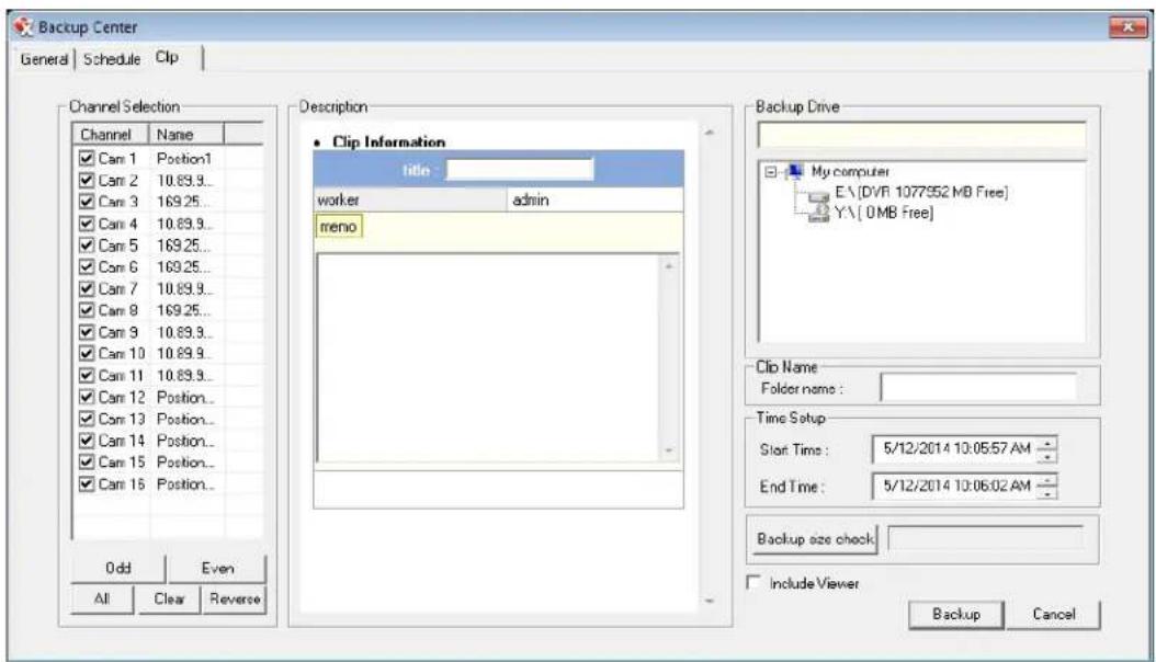
Performing a Clip Backup
- On the Display screen, click Backup.
- Click the Clip tab.
- Set the Start Time and End Time under Time Setup.
- Select the cameras to back up in the Channel Selection box.
- Select the Backup Drive to save the backup video to.
- Type the Folder Name for the clip files under Clip Name.
- Select Include Viewer to include the Backup Viewer software.
- Enter pertinent clip information into the Clip Information section in the Description box.
- Click Backup Size Check to confirm the file size of the clip backup.
- Click Backup to begin the backup process. A progress bar will be displayed in the lower right corner of the Display screen.
Scheduled Screen Overview
The Scheduled Backup Screen is used for performing bulk backup of video recorded by all cameras on a regular scheduled basis (1-24 hours). The Scheduled Backup Screen is similar to the General Backup Screen.
Activating Scheduled Backup
In order to use the Scheduled Backup feature, you must first activate the function for your Server software. You only need to do this once to enable scheduled backups.
- On the Live screen, click Exit, and then select Restart in Windows Mode.
- Click OK.
- Click Start, and then click vFormat.
- In the Need for Scheduled Backup area, click Confirm Windows System Password.
- Type your Windows System ID and Password.
Note The default ID is DVR Admin, and the default Password is dvr4321.
-
Click OK.
-
Close the DVR Utility window, and then double-click Surveillix Server to restart your Server software.
Specifying Scheduled Backup Drives
In order to use the Scheduled Backup feature one or more storage drives or partitions connected to the recorder must be specified as a backup drive.
- From the Display screen, click Exit and choose Restart in Windows Mode.
- Click OK.
- Double-click My Computer.
- Right-click on the drive to specify as a backup drive for Scheduled Backup and click Rename. Rename the drive to 'Backup'. Repeat this process for all drives to use for Scheduled Backup. To remove a drive from use for Scheduled Backup, change its name to something other than 'Backup'.
- Restart Surveillix and return to the Schedule tab in the Backup Center window.
Note The C: Drive CANNOT be used as a backup location; this is done intentionally to protect the operating system.
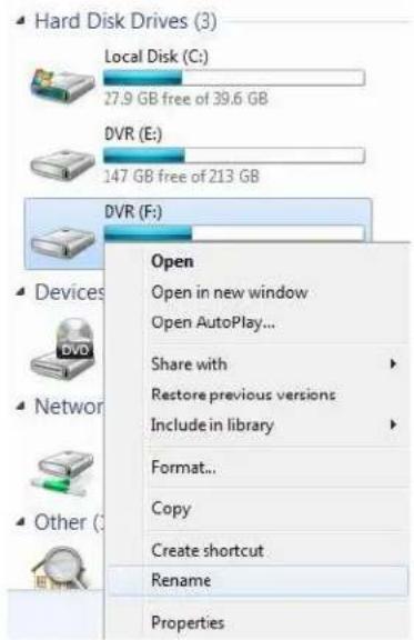
Performing a Scheduled Backup

- Click Backup on the Display screen.
- Click the Schedule tab at the top of the Backup Center window.
- Select the blocks of time to back up using the Hour/Minute Grid. Blocks of time with recorded video are highlighted in green. Blocks of time selected for backup are highlighted in red.
- Set the Backup Time to perform the backup.
- Set the Repeat Backup (Daily) time to specify the number of hours between backup procedures (between 1 and 24 hours).
- Select the Backup Drive to save the backup video under Select Backup Media or click Network Drive. To save to a local drive or partition you must first rename the location "BACKUP".
- Select Overwrite on Disk Full to overwrite previous backup files when the disk becomes full.
- Click Save Backup Setting to save the current backup setting and return to the Display screen.
LAN / ISDN / PSTN CONNECTIONS
This chapter includes the following information:
- Overview
- Configuring TCP/IP Settings
- Connecting to a LAN
• LAN / ISDN / PSTN Connections
The recorder can be easily connected to a Local Area Network (LAN) and uses Microsoft's® powerful and secure Windows® 7
Embedded operating system. This allows for easy and well-documented instructions on setting up LAN connections no matter what type of LAN you want to use.
A LAN is a group of computers and other devices dispersed over a relatively limited area and connected by a communications link that allows one device to interact with any other on the network.
There are many reasons why using Microsoft® Windows® 7 Embedded is superior to other platforms when running on a LAN. The number one reason is security. Windows 7 Embedded is based on the Microsoft's Windows platform, which, historically has boasted the most reliable and secure operating system in the world. Running the recorder on a secure network is important to prevent unwanted users from gaining access to confidential information. Unwanted users can compromise the integrity of the confidential data being stored and viewed, and in extreme circumstances can cause irreparable damage to the network.
Since connecting the recorder to a network can be extremely complex (depending on the network), this Surveillix recorder manual will cover only the basics. It is suggested that the recorder administrator consult the Vendor or IT Administrator before attempting to create or connect to a LAN.
CONNECTING TO A LAN USING TCP/IP
The networking options of the recorder can be created and modified via the standard networking options available on Windows 7
Embedded. The recorder comes equipped with a 10/100/1000 Network Interface Card (NIC). This card uses a standard RJ-45 connector, and should be connected using CAT5 Ethernet cable to achieve optimal communication speeds.
Configuring TCP/IP Settings
- On the Display screen, click Exit and select Restart in Windows Mode.
- Right-click Network on the desktop and select Properties.
- Click Local Area Connection.
- Click Properties.
- Select Internet Protocol Version 4 (TCP/IPv4), then click Properties.
- Select Use the Following IP Address option. Enter the IP Address and Subnet mask appropriate for the network. It is recommended to contact the Network Administrator for appropriate IP settings.
Example: a. Common IP addresses are 192.168.0.25 or 10.0.0.25
b. Common Subnet masks are 255.255.255.0 or 255.0.0.0
Note In order to connect to the recorder through a remote LAN connection, a static IP address must be assigned. If the network assigns the IP address automatically (DHCP), contact the Network Administrator for help assigning a static IP address.
- If the network requires you to specify the DNS information, enter it now by selecting the appropriate DNS options.
- When finished configuring the TCP/IP settings click OK to close the Internet Protocol (TCP/IP) Properties window.
- Click Close and then Close again to close both Local Area Connection Properties windows.
LDAP INTEGRATION
This chapter includes the following information:
- Installing LDAP
The instructions below are for LDAP with Server Software version 3.6.36 and above.
- The recorder server does not need to be joined to the Domain. The recorder server will query the LDAP server for accounts and authorization levels.
- The recorder server creates groups within LDAP for each of the permissions on the recorder. Simply join a Domain user to these groups to provide access to that function in the recorder.
- Recorder access within LDAP is based on the Site Code within the recorder software. This allows an administrator to group recorders with the same Site Code.
- Remote and Multi-Site management software works with LDAP logins.
INSTALLING ACTIVE DIRECTORY
Required Items
- Name of LDAP server.
-
Account in LDAP server that has Domain Admin rights. This user will be used initially to create the OU's and Groups within LDAP.
-
Verify that the recorder server is connected to a network that has a valid LDAP server. Ensure that the TCP/IP settings are configured correctly for DNS resolution and gateway if needed. Check to verify that you can ping the LDAP server without issues.
-
Set up DVR Site Code to be used for LDAP authorization. The default will be 100-000. This site code can be used to group recorders together within LDAP.
g) Log in to the recorder using the local recorder administrator account (non-Active Directory).
h) Navigate to the Setup -> Information tab and change the Site Code.
- Log on to the recorder server with the domain account with administrator privileges (see above required items). If successful, the recorder will log the administrator user on without any error messages. You may log off the recorder once this is completed without errors.
Note If you encounter an error please verify that the above required items are correct.
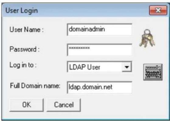
- Go to the Active Directory Users and Computers application. You should now see an OU called DVR with an OU inside of it named the same as the Site Code above (example 100-000).
![Active Directory Users and Computers [EC 100-000 32 objects] Name Type DVR_BACKUP_100-000 Distribution Group - Universal DVR_HIDE_AUDIO_001_100-000 Distribution Group - Universal DVR_HIDE_AUDIO_002_100-000 Distribution Group - Universal DVR_HIDE_AUDIO_003_100-000 Distribution Group - Universal DVR_H…](/content/2026/06/1148326/images/1a21f592a14e35e5cf19becb4f42c4d0fbc3e60f94f56e476f496f17b1cd3ebc.jpg)
- You can now add users within Active Directory to the groups the recorder has created. When a user belongs to a group he or she will have access (or be denied access in the case of Audio or Camera channels) to that permission on any recorders with that site code.
| Group | Description |
| DVR_BACKUP_100-000 | Backup access to DVRs with site code 100-000 |
| DVR_HIDE_AUDIO_0XX_100-000 | Hides audio channel XX for site code 100-000 |
| DVR_HIDE_CAMERA_0XX_100-000 | Hides camera XX for DVRs - site code 100-000 |
| DVR_INSTANT_100-000 | Instant recording access to DVR |
| DVR_PTZ_100-000 | PTZ access to DVRs - site code 100-000 |
| DVR_PTZEX_100-000 | Access to advanced PTZ control |
| DVR_RELAYOUT_100-000 | Access to toggle relays from live view |
| DVR_SEARCH_100-000 | Access to search on DVRs - site code 100-000 |
| DVR_SETUP_100-000 | Access to setup on DVRs - site code 100-000 |
| DVR_SHUTDOWN_100-000 | Grants the ability to shut down the DVR server |
Note The above site codes may be different depending on what site code the recorder server had when it was logged into LDAP.
- You can now log in to the recorder server using any of the Active Directory users who belong to one of the above groups.
WEB VIEWER
This chapter includes the following information:
- Overview
- Configuring the Web Viewer
The recorder allows you to access video using Microsoft® Internet Explorer® 7 and above.
Highlights:
• View Live Video from most computers
- Username and Password protected
- Easy to use graphical interface
Basics:
75 users can access the Web Viewer simultaneously (if network bandwidth allows). The Web Viewer is an easy, secure way to view live video from virtually any computer with an internet connection using Microsoft Internet Explorer.
In order to log in to the recorder server, a user account must be made for the user. This ensures that only authorized personnel are allowed to log in. In addition, each user can be assigned different privileges that allow them or deny them access to different cameras. For example: a user can be granted access to only view cameras 4, 8 and 16.
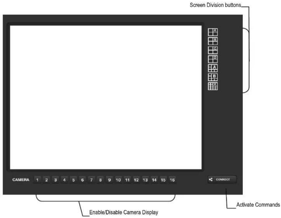
Configuring the Recorder for Remote Connection
- In the Display screen, click Setup.
- Click Network Setup.
- Select Enable Web Viewer.
Note If you are using a Firewall, it may be necessary to adjust the port settings on both the recorder and the Firewall. Contact the Network Administrator for more information.
- Click Apply.
Note If no additional user accounts have been created the administrator account will be the only account that can connect to the recorder remotely.
- The recorder server is now ready to receive incoming connections from Remote Software, SCS, the Surveillix App, or the Web Viewer.
Connecting to a Recorder Using Web Viewer
- Open Microsoft Internet Explorer.
-
Type the IP address of the recorder into the Address Bar.
-
When attempting this for the first time on a workstation a prompt will ask you to accept an ActiveX installation. Select Yes.
Note If you receive a message saying Internet Explorer® security settings do not allow you to download ActiveX components then you will need to adjust the browser security settings. One way to do this is to add the IP address of the recorder to the trusted sites list inside Internet Explorer® settings. Contact your System Administrator for additional help with adjusting Internet Explorer settings.
- When the Web Viewer finishes loading, click GO!
- Type the Username and Password of an authorized user.
- The cameras will display.
Closing the Web Viewer
To exit the Web Viewer close Internet Explorer.
INCLUDED SOFTWARE SETUP
This chapter includes the following information:
• The Surveillix App Overview
• Emergency Agent Overview
- Remote Software Overview
- Digital Verifier
- Backup Viewer
The Toshiba Surveillix App software, available for iPhone, Android, and Blackberry, allows you to access your Surveillix recorder from almost anywhere on your mobile device. The Toshiba Surveillix App gives you the ability to view live video from your cameras using a simple interface.
For a list of supported models, installation instructions and download links, go to http://www.toshibasecurity.com/mobile_apps.jsp
EMERGENCY AGENT OVERVIEW
The Emergency Agent software is a utility that streams video across a Local Area Network to a Client PC when an alarm is detected on the recorder. The video that streams across can be stopped, played forwards and backwards, in slow motion or real speed.
The utility is loaded at startup and placed in the taskbar. It constantly monitors for a signal from the recorder. When an alarm signal is detected the Emergency Agent Image Viewer window opens and starts playing the video from the camera associated to the alarm.
Configuring the Recorder
To enable the Emergency Agent on the recorder follow these steps:
- From the Display screen, click Setup.
- Click Camera.
- Select a camera and associate sensors to that camera using Sensor Connection option.
- Click Network and make sure that Disable Remote Control is cleared.
Note The Emergency Agent uses one port to transfer the data through the network (the Emergency Port). The port can be adjusted inside the Network menu if necessary. It is recommended that the default setting should be used unless the port must be changed.
-
Click Schedule.
-
Enter the IP Address of the workstation running the Emergency agent software under Emergency IP section.

- Click the box next to the IP Address to enable it.
- Select the Sensor option and create a schedule for the appropriate sensor (see the Schedule Setup chapter in this manual for further details).
- Click Apply, then click Exit Setup.
Configuring the Client PC
All configurations take place in the Emergency Agent window on the Client PC for descriptions and locations of the buttons and features of the Emergency Agent window refer to the Emergency Agent window section later in this chapter.
- Open the Emergency Agent window on the Client PC - Start >All Programs >Surveillix >Emergency Agent >Emergency Agent.
- Right-click in the DVR List and select New. Enter the DVR Code, DVR Name, and IP Address of the recorder.
- Click the Options menu and select Setup.
- Confirm that the Network Port in the Setup window is set to the same number as the Emergency Port in Network Settings on the recorder. If the numbers are different adjust the Network Port on the client PC to match the recorder.
- Click OK.
- Restart the Client PC.

Setup Window
Network Port
Indicates the port which the Emergency Agent uses to listen for incoming events. This number should be changed to the same number as is set in the Emergency Port in Network Settings on the recorder.
Save Directory
Sets the location that recorded video footage is saved to.
Notice Options
Configuration settings for activating an audible indicator or popup window when the Emergency Agent receives an event.
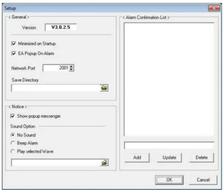
Emergency Agent Window
![Emergency Agent File Option DVRI LIST Code Name IP Data No Video Thumbnails Video Display DVR List Event Level Event Event List Edit Memo Save Memo Filter Options Data: 5V 5/2008 Off On Server: All-Date Event: [AllAlarm] Confirmed: All Types Images: 20 100x120 Status Setting Level Default Confined S…](/content/2026/06/1148326/images/81dd69db4329141646c38eb6869085cf69cfd111782fbd10c68a690423ed4080.jpg)
Filter Event List
- Select a recorder from the DVR List in the Filter Options section.
- Select the Date to include.
- Select the type of Events to include.
- Select the event levels (Review, Dismiss, Critical, Default).
- Click the On button to display filtered event listings.
Add Items to Alarm Confirm List
- From the Option menu, click Setup.
- Type the desired text in the box below the Alarm Confirmation List.
Note The items in the Alarm Confirmation List will be available on a list under Status Setting on the main Emergency Agent screen.

- Click Add.
- Click OK to save changes and close the window.
![Status Setting Level Default Confirmed [Select Type] [Select Type] Raccoons Delivery Truck Suspected Theft](/content/2026/06/1148326/images/1df66f9fe249e9667145d376e477f8d362fee25c6d9f07a09195ab666cb8c857.jpg)
Search Alarm Window

Export Quality
It may be necessary to reduce the overall size of an AVI file; for example, to email to someone. AVI file sizes can be reduced by reducing the image quality. However, reducing the image quality causes the AVI video to appear more pixilated. When size is not an issue, setting quality to 100 is highly recommended.
Digital Signature
Adds a digital signature to the exported JPG image for use with the Digital Signature Verifier to verify integrity of exported images and prevent tampering.
View Recorded Video
- Double-click an event listing to open the Search Alarm window.
- Use the play controls to locate the desired video.
- Select the Continue Playing check box to watch all recorded events. When cleared, playback stops at the end of the alarm event.
- Select the Same Camera check box to watch all events recorded by a single camera.
- Click Apply after making any changes.
Export Video
- Double-click an event listing to open the Search Alarm window.
- Use the play controls to locate the desired video.
- Click the Rewind button to return to the beginning or desired spot in the video.
- Click the Stop button.
- Select the Export Option – JPG or AVI.
- Select the Digital Signature check box to embed a digital signature in a JPG file.
- Reduce Export Quality only if necessary to reduce the size of the AVI file.
- Click Export.
The recorder was specifically designed to be fully operated and maintained remotely. It connects using the standard TCP/IP protocol thorough connection types such as DSL, Cable Mode, T1, ISDN, LAN, and more. The Surveillix Remote software allows you to view live video, search through archived video, export images and video clips and have virtually full Setup control. Surveillix Remote Software is Microsoft® Windows XP®, Windows Vista®, and Windows 7® compatible.
Highlights:
- Search archived video
• View live video - Export images and video clips
• Control relay outputs - Setup administration
Basics:
The recorder can have up to 5 simultaneous remote connections. Each user can perform functions on the recorder and will not affect the other users. The only exceptions to this are accessing Setup and controlling a PTZ camera. Only one user is allowed to access setup or control a PTZ camera at any given time. The pictures per second passed to the Remote Client vary greatly depending on the connection type and speed.
In order to log in to the recorder server, a user account must be made for the user. This ensures that only authorized personnel are allowed to log in. In addition, each user can be assigned different privileges that allow them or deny them access to different functions. For example: a user can be denied Searching and Setup privileges and only granted access to view cameras 4, 8 and 16.

It is highly recommended that users not be granted Setup privileges since this can pose a security risk. Only properly authorized Administrators should have access to Setup.
The Remote software operates virtually the same way as the recorder itself. The appearance of it matches the recorder almost identically; however, there are a few minor differences. Some search features are not available (such as the Index and Object Searches) as well as some Setup options.
Remote Software Setup
Installing Remote Software
- On the client workstation, insert the Surveillix Software CD into the CD-ROM. The CD should play automatically.
- When prompted, select the Install Remote Software option. Follow the installation instructions carefully.
- When the software finishes installing, close any open installation windows.
Create a New Remote Connection
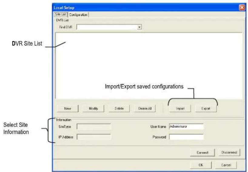
- Select Start > Programs > Surveillix > Remote > Surveillix Remote Center. The Surveillix Remote Software opens and the Local Connection window opens.
- Click New to open the Site Info window.
- Select the Site Type and enter a Site Name. The Site Name will be the name displayed inside the connection box to help identify the unit.
- Enter the IP Address of the recorder.
- Enter the Center Port. This setting is specified in the server software.
- Click OK.
- Click on the newly created connection and enter the login username and password (case sensitive).
- Click Connect.
Configuring the Recorder
In order to access the recorder remotely, the recorder Server must be setup to allow remote connections.
Time Out Value
Specifies a value (in seconds) to wait for a signal from the Surveillix Remote Client. If a signal is not received by that time, the connection is dropped.
Center Port
Used to transfer the connection data.
Image Port
Used to transfer the image data.
Search Port
Used to transfer the search data.
Network Setup
TimeOut Value : 60
Emergency Port: 2001
(1024 - 5000)
Center Port : 2000
(1024 - 5000)
Image Port: 2002
(1024 - 5000)
Search Port: 2003
(1024 - 5000)
JPG images and AVI video files that are exported from the Digital Video Recorder are automatically embedded with a digital signature. Digital Signatures are a way to verify the authenticity of the images to ensure that they have not been tampered with or edited in any way. Included on the Software Installation DVD supplied with the recorder is the Digital Signature Verification program. This program can be installed on any computer and loads an image in question.
Installing the Digital Verifier
- Insert the Software Installation CD into the CD-ROM. (Do not install on the recorder.)
- Select the Digital Verifier option to begin installation.
- When the Welcome screen appears, click Next.
- When the Setup Complete window appears click Finish. Installation is complete.
Using the Digital Verifier
- Open the Digital Verification program by selecting Start > Programs > Surveillix > Digital Verifier > Digital Signature Verifier.
- Click the Browse button to load the JPG image.
- Enter the Site Code of the recorder that the image was originally extracted from. (The Site Code is specified in the Information Setup menu)
- Click Verify to continue or Close to close the window without verifying.
If the image has not been tampered with, a blue square will appear around the image with the message "Original image file."

If the image has been tampered with, a red square will appear around the image with the message "Entire image changed or wrong SITE CODE."
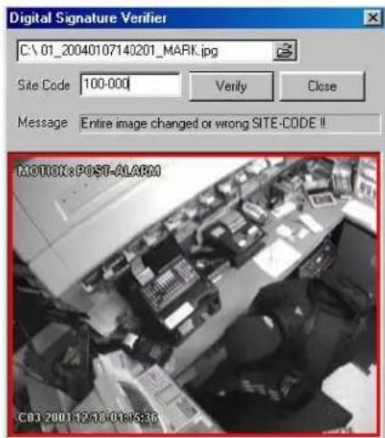
The Backup Viewer allows you to play back the exported video in its proprietary format. Video saved in this format is extremely difficult to tamper with and therefore is the ideal solution when law enforcement and the legal department are involved. This video cannot be read by any other viewer. The Backup Viewer operates essentially like the Search portion of the recorder software.
For detailed explanations of these functions, refer to the chapter on Search Options in this manual.
Installing Backup Viewer
- Insert the Software Installation DVD into the DVD-ROM. (Do not install on the recorder.)
- Select the Backup Viewer option to begin installation. When the Welcome screen opens, click Next.
- Read the License Agreement and select the appropriate radio button to accept the terms of the license agreement. Click Next.
- Select Yes to install the POS component or select No for a basic install. Click Next.
Note The POS component is only necessary when connecting to a server running the POS Upgrade.
-
When the Choose Destination Location window opens click Next. This will install Backup Viewer in the default destination folder.
-
Select the shortcuts to install, or clear all boxes for no shortcuts. Click Next.
-
When the InstallShield Wizard Complete window appears click Finish. Setup is now complete.
Loading Video from DVD or Hard Drive
-
Open the Backup Viewer program: Start > Programs > Surveillix > Backup Viewer > Backup Viewer.
-
Click Open. The Total Backup Search window will open.
-
Open the Backup Viewer program: Start > Programs > Surveillix > Backup Viewer > Backup Viewer.
- Click Open. The Total Backup Search window will open.
a) For DVD-ROM data, select the appropriate DVD-ROM drive letter from the Backup Media box.
b) For hard drive data, select either an attached hard drive from the Backup Media box or select the Open Folder icon to browse to a specific directory.
a) For DVD-ROM data, select the appropriate DVD-ROM drive letter from the Backup Media box.
b) For hard drive data, select either an attached hard drive from the Backup Media box or select the Open Folder icon to browse to a specific directory.
Note Once selected, available video data will be displayed in the Choose Start Hour box.
-
Click on the desired time to select it.
-
Click OK. The video will now load into the Backup Viewer.
-
Click on the desired time to select it.
- Click OK. The video will now load into the Backup Viewer.

SCS Overview
SCS software is Network DVR Management Software; a powerful utility that allows 100 or more recorders to be controlled using one computer. This software allows you to view live video, search saved video, edit and configure setup on each recorder, and import maps of buildings and other locations.
The SCS software was specifically designed as an enterprise software solution.
Highlights:
• View Live Video on most computers
- Username and Password protected
- Easy to use graphical interface
Basics:
In order to log in to the recorder server, a user account must be made for each user. This ensures that only authorized personnel are allowed to log in. In addition, each user can be assigned different privileges that allow them or deny them access to different functions.
Connecting to a Recorder
Refer to the Setup section of the SCS Manual for information on using the SCS Software.
- LIMITED THREE (3) YEAR WARRANTY OF LABOR AND PARTS
- STEP-BY-STEP PROCEDURES - HOW TO OBTAIN WARRANTY SERVICE
- WWW.TOSHIBASECURITY.COM
- CRITICAL USE DISCLAIMER
- YOUR RESPONSIBILITIES
- TOSHIBA AMERICA INFORMATION SYSTEMS, INC. IMAGING SYSTEMS DIVISION
- IMPORTANT SAFEGUARDS
- IMPORTANT SAFEGUARDS, CONTINUED
- BATTERY EXPLOSION CAUTION STATEMENT
- NOTES ON HANDLING
- NOTES ON LOCATING
- NOTES ON MAINTENANCE
- NOTES ON MOISTURE CONDENSATION
- WARNING
- CAUTION
- RACK MOUNT INSTRUCTIONS
- FCC STATEMENT
- DISCLAIMER
- USAGE LIMITATION
- TABLE OF CONTENTS
- PREFACE....15
- INTRODUCTION ....16
- CONTROLS AND CONNECTIONS....18
- GETTING STARTED....22
- DVR BASICS 29
- SETUP OPTIONS....36
- PREFACE
- ABOUT THIS GUIDE
- TECHNICIAN NOTES
- INTRODUCTION
- PRODUCT DESCRIPTION
- CONTROLS AND CONNECTIONS
- FRONT PANEL CONTROLS
- XVSV
- 240V PPS 16 CHANNEL
- GETTING STARTED
- IDENTIFYING INCLUDED COMPONENTS
- UPS UPS POWER BACKUP
- NP-4PKVM 4 CHANNEL KVM SWITCH
- EXTERNAL RAID STORAGE
- GIGABIT NIC
- SSD
- DUAL GIGABIT NIC
- MOUSE SETUP
- POWER SETUP
- CONNECTING A PTZ CAMERA
- ATTACHING THE 4-PIN ADAPTER
- DVR BASICS
- SETTING THE TIME AND DATE
- ACCESSING THE DVR UTILITY
- EXPORTING SETTINGS
- IMPORTING DVR SETTINGS
- CHANGING VIDEO FORMAT
- CPU METER
- LIVE CAMERA OPTIONS
- RECORDING STATUS INDICATOR
- SPECIAL RECORDING
- SENSOR
- INSTANT
- SCREEN DIVISION BUTTONS
- CUSTOM LIVE VIEW DIVISIONS
- SETUP OPTIONS
- SETUP OVERVIEW
- SETUP MENU OVERVIE
- SELECT CHANNEL
- SELECTED CAMERA DISPLAY
- SENSOR CONNECTION
- CAMERA NAME
- SET UP NEW CAMERA
- MAXIMUM FPS TABLE
- FRAME SELECT
- RESOLUTION
- CODEC
- VIDEO QUALITY
- SENSITIVITY
- CONNECTING A NETWORK DEVICE
- CONNECTING MANUALLY
- CONNECTING WITH FIND CAMERAS
- NAMING CAMERA CHANNELS
- ASSIGNING DUAL STREAMS
- REMOVING A CAMERA
- ASSIGNING AUDIO CHANNELS TO A NETWORK DEVICE
- ALARM RECORDING MODE
- CAMERA STATUS AND INFORMATION
- DVR REGISTRATION AND UPGRADE
- LOCATING THE SYSTEM ID
- LICENSE INFORMATION
- OBTAINING THE LICENSE KEY
- UNLOCKING THE UPGRADE
- UNLOCKING ADDITIONAL NETWORK DEVICES
- CREATE A MOTION AREA
- ETC
- ENABLING AN ANALOG PTZ CAMERA
- ENABLING AN IP PTZ CAMERA
- USING THE GRAPHICAL PTZ CONTROLLER
- USING THE ON-SCREEN COMPASS
- AUDIO
- CONFIGURE AUDIO CHANNELS
- SYSTEM VOLUME
- AUDIO CHANNELS
- VOICE WARNING
- DISPLAY
- DISPLAY OPTIONS
- GENERAL
- SEQUENCING
- AUTO SEQUENCE
- CREATE CUSTOM AUTO SEQUENCE
- ALARMS
- SENSORS
- CONFIGURE SENSORS
- ACTIVATE PTZ PRESET
- HYBRID SENSOR SETUP
- RELAYS
- DEFAULT SCHEDULES
- DEFAULT SCHEDULE 1
- DEFAULT SCHEDULE 2
- DAY OF THE WEEK
- CREATING A RECORDING SCHEDULE (EXAMPLE)
- THIS EXAMPLE SCHEDULE WILL BE AS FOLLOWS
- SETTING DAYTIME MOTION DETECTION (EXAMPLE)
- SETTING NIGHTTIME CONTINUOUS RECORDING
- SETTING WEEKEND MOTION RECORDING
- CREATING A SENSOR SCHEDULE (EXAMPLE)
- THIS SCHEDULE EXAMPLE WILL BE AS FOLLOWS
- SPECIAL DAY SCHEDULE
- CREATING/EDITING A 'SPECIAL DAY' SCHEDULE
- DELETING A 'SPECIAL DAY' SCHEDULE
- ALARM OPTIONS
- SETTING A RESTART SCHEDULE
- CREATE SYSTEM RESTART SCHEDULE
- ADD A NEW USER
- USER RANK
- CHANGING THE ADMINISTRATOR PASSWORD
- DEFAULT ADMINISTRATOR PASSWORD
- STATUS CHECK / EMAIL
- USERS
- STORAGE CHECK
- RECORDING DATA CHECK
- SMART ALERT
- ALARM EVENT
- MYSURVEILLIX
- SMART INFORMATION
- DATA MANAGEMENT
- FILE MANAGEMENT
- STORAGE MANAGEMENT
- SYSTEM INFORMATION
- BASIC INFORMATION
- PROGRAM MANAGEMENT
- SENG UP DDNS
- ENABLE DDNS
- SET THE IP ADDRESS
- INFORMAON COLLECON
- PERFORMANCE MONITOR
- LOG FILES
- VIEWING LOG FILES
- EXPORTING LOG FILES
- SET UP LOG MANAGEMENT OPTIONS
- ACTIVATE INSTANT RECORDING
- SEARCHING 'INSTANT RECORDED' VIDEO
- SEARCH
- PLAY CONTROLS
- ADJUST THE BRIGHTNESS OF AN IMAGE
- ZOOMING IN ON AN IMAGE
- ZOOMING IN ON A PORTION OF AN IMAGE
- OPEN VIDEO FROM A SAVED LOCATION
- SYNC
- CLEAN IMAGE
- PERFORMING A BASIC SEARCH
- PRINTING AN IMAGE
- BOOKMARKS
- MODIFY BOOKMARKS
- CLIP BACKUP
- SINGLE CLIP BACKUP USING BOOKMARK DATA
- PERFORMING AN INDEX SEARCH
- INDEX SEARCH RESULTS DISPLAY
- PERFORMING A PREVIEW SEARCH
- STATUS SEARCH
- PERFORMING A STATUS SEARCH
- PERFORMING AN OBJECT SEARCH
- PERFORMING A MOTION SEARCH
- AUDIO PLAYBACK
- PAN / TILT / ZOOM
- BASIC PTZ CONFIGURATION
- PTZ ADDRESS SETTINGS
- PTZ PRESETS/TOURS
- CREATING A PRESET
- VIEWING A PRESET
- ACCESSING PTZ MENUS
- CONTROLLING A PTZ CAMERA
- UNDERSTANDING TOURS
- PTZ TOUR SCHEDULE
- NERO® EXPRESS
- GENERAL BACKUP OVERVIEW
- HOUR / MINUTES
- BACKUP STATUS
- FIXED HDD
- PERFORMING A GENERAL BACKUP
- CLIP BACKUP OVERVIEW
- PERFORMING A CLIP BACKUP
- SCHEDULED SCREEN OVERVIEW
- ACTIVATING SCHEDULED BACKUP
- SPECIFYING SCHEDULED BACKUP DRIVES
- PERFORMING A SCHEDULED BACKUP
- LAN / ISDN / PSTN CONNECTIONS
- CONNECTING TO A LAN USING TCP/IP
- CONFIGURING TCP/IP SETTINGS
- LDAP INTEGRATION
- INSTALLING ACTIVE DIRECTORY
- REQUIRED ITEMS
- WEB VIEWER
- HIGHLIGHTS
- BASICS
- CONFIGURING THE RECORDER FOR REMOTE CONNECTION
- CONNECTING TO A RECORDER USING WEB VIEWER
- CLOSING THE WEB VIEWER
- INCLUDED SOFTWARE SETUP
- EMERGENCY AGENT OVERVIEW
- CONFIGURING THE RECORDER
- CONFIGURING THE CLIENT PC
- SETUP WINDOW
- NETWORK PORT
- SAVE DIRECTORY
- NOTICE OPTIONS
- FILTER EVENT LIST
- ADD ITEMS TO ALARM CONFIRM LIST
- SEARCH ALARM WINDOW
- EXPORT QUALITY
- DIGITAL SIGNATURE
- VIEW RECORDED VIDEO
- EXPORT VIDEO
- REMOTE SOFTWARE SETUP
- INSTALLING REMOTE SOFTWARE
- CREATE A NEW REMOTE CONNECTION
- TIME OUT VALUE
- CENTER PORT
- IMAGE PORT
- SEARCH PORT
- INSTALLING THE DIGITAL VERIFIER
- USING THE DIGITAL VERIFIER
- INSTALLING BACKUP VIEWER
- LOADING VIDEO FROM DVD OR HARD DRIVE
- SCS OVERVIEW
- CONNECTING TO A RECORDER
Brand : TOSHIBA
Model : XVSV
Category : Video camera