GNSF39A - Water filter GE - Free user manual and instructions
Find the device manual for free GNSF39A GE in PDF.

User questions about GNSF39A GE
0 question about this device. Answer the ones you know or ask your own.
Ask a new question about this device
Download the instructions for your Water filter in PDF format for free! Find your manual GNSF39A - GE and take your electronic device back in hand. On this page are published all the documents necessary for the use of your device. GNSF39A by GE.
USER MANUAL GNSF39A GE
Proper installation ....3
Installation Instructions
Drain connections .....7
Important recommendations ....4
Installation instructions .....4-6
Planning and location .....5
Programming the control .....9
Sanitizing ....10
Specifications and dimensions ..11
Step-by-step instructions .....7-11
Tools and materials required .....5
Unpacking and inspection .....4
Operating Instructions, Tips
Breaking a salt bridge .....13
Cleaning nozzle and
venturi assembly .....14
Electronic diagnostics .....18
Features....15-17
Regenerating the system ....19, 20
Service ....12
Water softener system .....12-21
Care and Cleaning
Salt storage level and refilling ....22
Cleaning out iron .....22
Troubleshooting Tips .....23-25
Customer Service
Appliance registration .....33, 34
Important phone
numbers......Back Cover
Parts list/catalog .....26-29
Warranty....35
Owner's Manual & Installation Instructions
GNSF39A01
GNSF48A01

natural_image
Abstract decorative swirl pattern with no text or symbols
IMPORTANT!
Fill out the Consumer Product Registration Card.
Two easy ways to register your appliance!
■ Through the internet at www.geappliances.com
■ Complete and mail the enclosed Product Registration Card

FOR YOUR RECORDS
Write the model and serial numbers here:
#
#
You can find them on the back of the control head.
Staple sales slip or cancelled check here.
Proof of the original purchase date is needed to obtain service under the warranty.

READ THIS MANUAL
Inside you will find many helpful hints on how to use and maintain your water system properly. Just a little preventive care on your part can save you a great deal of time and money over the life of your system.
IF YOU NEED SERVICE
You'll find many answers to common problems in the Before You Call For Service section. If you review our chart of Troubleshooting Tipsfirst, you may not need to call for service at all.
If you do need service, you can relax knowing help is only a phone call away. A list of toll-free customer service numbers is included in the back section.
OR
Visit our website at: www.geappliances.com.
WARNING!
For your safety, the information in this manual must be followed to minimize the risk of electric shock, property damage or personal injury.

SAFETY PRECAUTIONS
■ Check and comply with your state and local codes. You must follow these guidelines.
■ Use care when handling the water softening system. Do not turn upside down, drop, drag, or set on sharp protrusions.
■ Water softening systems using sodium chloride (salt) for regeneration add sodium to the water. Persons on sodium restricted diets should consider the added sodium as part of their overall intake. Potassium chloride can be used as an alternative to sodium chloride.
■ The water softening system works on 24 volt-60 Hz electrical power only. Be sure to use only the included transformer.
- Keep the salt hole cover in place on the softener unless servicing the unit or refilling with salt.
▲ WARNING: Do not use with water that is microbiologically unsafe or of unknown quality without adequate disinfection before or after the system.

PROPER INSTALLATION
This water softening system must be properly installed and located in accordance with the Installation Instructions before it is used.
■ Install or store where it will not be exposed to temperatures below freezing or exposed to any type of weather. Water freezing in the system will break it. Do not attempt to treat water over 100^ F.
■ Do not install in direct sunlight. Excessive sun heat may cause distortion or other damage to non-metallic parts.
■ Properly ground to conform with all governing codes and ordinances.
■ Use only lead-free solder and flux for all sweat-solder connections, as required by state and federal codes.
■ The water softening system requires a minimum water flow of three gallons per minute at the inlet. Maximum allowable inlet water pressure is 125 psi. If daytime pressure is over 80 psi, nighttime pressure may exceed the maximum. Use a pressure reducing valve to reduce the flow if necessary.
■ Softener resins may degrade in the presence of chlorine above 1 ppm. If you have chlorine in excess of this amount, you may experience reduced resin life. In these conditions, you may wish to consider purchasing a GE point-of-entry household filtration system with a chlorine reducing filter. Contact the GE Answer Center at 1-800-626-2000 for more information.

WARNING: Discard all unused parts and packaging material after installation. Small parts remaining after the installation could be a choke hazard.

Read and follow this Safety Information carefully.
SAVE THESE INSTRUCTIONS

CAUTION: Certain plumbing skills are needed for installation. If you are unsure about any part of the installation of this product, consult a professional plumber.
Unpacking and Inspection
Be sure to check the entire softener for any shipping damage or parts loss. Also note damage to the shipping cartons. Contact the transportation company for all damage and loss claims. The manufacturer is not responsible for damages in transit.
Small parts, needed to install the softener, are on a skin-packed cardboard piece. To avoid loss of the small parts, keep them on the skin-pack until you are ready to use them.
Important Installation Recommendations
Read entire manual. Failure to follow all guidelines and rules could cause personal injury or property damage.
- Before you begin installation, read these Installation Instructions completely. Then, obtain all the materials and tools you will need to make the installation. Failure to properly install the softener voids the warranty.
- Check local codes. The installation must conform to them.
- In the Commonwealth of Massachusetts, Plumbing Code 248 CMR shall be adhered to. Consult with your licensed plumber.
- Use only lead-free solder and flux for all sweat-solder connections, as required by state and federal codes.
- Connect the softener to the main water supply pipe before or ahead of the water heater. DO NOT RUN HOT WATER THROUGH THE SOFTENER. Temperature of water passing through the softener must be less than 120^ F.
- Use care when handling the softener. Do not turn upside down, drop, drag, or set on sharp protrusions.
- Maximum allowable inlet water pressure is 125 psi. If daytime pressure is over 80 psi, nighttime pressure may exceed the maximum. Use a pressure reducing valve if necessary. (Adding a pressure reducing valve may reduce the flow.)
- The softener works on 24 volt-60 Hz electrical power only. Be sure to use the included transformer. Be sure the electric outlet and transformer are in an inside location to protect from wet weather.
- See Where to Install the Softener section for more details.

WARNING: Do not use with water that is microbiologically unsafe or of unknown quality without adequate disinfection before or after the system. The water should be tested periodically to verify that the system is performing satisfactorily.
Small parts remaining after the installation could be a choke hazard. Discard safely.
Plan How You Will Install the Softener
You must first decide how to run in and out pipes to the softener. Look at the house main water pipe at the point where you will connect the softener. Is the pipe soldered copper, glued plastic, or threaded galvanized? What is the pipe size?

WARNING: Use only lead-free solder and flux to prevent lead poisoning.
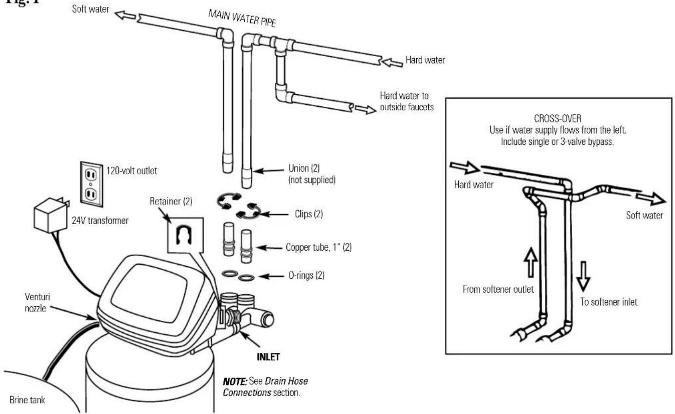
See Typical Installation Illustration, Fig.1. Use this as a guide when planning your particular installation. Be sure to direct the incoming hard water supply to the softener valve inlet fitting. The valve is marked IN and OUT. See below to help you prepare.
Where to Install the Softener
- Place the softener as close as possible to a sewer drain, or other acceptable drain point or standpipe.
- It is recommended to keep outside faucets on hard water to save soft water and salt.
- Do not install the softener in a place where it could freeze. Freeze damage is not covered by the warranty.
- Do not install the softener where it would block access to the water heater or access to the main water shutoff.
- Do not locate the brine tank more than 10 feet away from the resin tank.
- Put the softener in a place where water damage is least likely to occur if a leak develops. The manufacturer will not repair or pay for water damage.
- A 120 volt electric outlet is needed to plug in the included transformer. The softener has a 10 foot power cable. If the outlet is remote (up to 100 feet), use 18 gauge wire to connect. Be sure the electric outlet and transformer are in an inside location, to protect from wet weather. Be sure the outlet is unswitched to prevent accidental shutoff.
- If installing in an outside location, you must take the steps necessary to assure the softener, installation plumbing, wiring, etc., are as well protected from the elements (sunlight, rain, wind, heat, cold), contamination, vandalism, etc., as when installed indoors.
- Keep the softener out of direct sunlight. The sun's heat may distort non-metallic parts and may damage the electronics.
Tools and Materials Required for Installation
- In and out fittings included with the softener are 1" (nominal) copper sweat tubes. To maintain full valve flow, 1" pipes to and from the softener fittings are recommended. You should maintain the same, or larger, pipe size as the water supply pipe, up to the softener inlet and outlet.
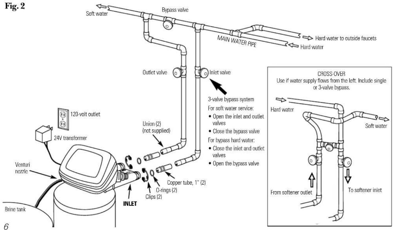
- Use the included bypass valve to install the softener. The bypass valve allows you to turn off water to the softener for servicing, but still have water in the house pipes. The in and out fittings referred to above connect to the bypass valve with the included nuts and washers.
- Use copper, brass or galvanized pipe and fittings. Some codes may also allow CPVC plastic pipes.
- If additional drain hose is needed for salt tank drains, it can be ordered from GE Parts at 800.626.2002.
- Garden hose with female fitting is needed for valve drain (sufficiently long to reach suitable drain).
- If a rigid valve drain is needed to comply with plumbing codes, you can buy the parts needed to connect a 1/2" copper tubing or plastic drain.
- Clean nugget or pellet water softener salt is needed to fill the brine tank, see Step 8 in the Step-by-Step Installation Instructions.
Typical Installation Illustration
Fig. 1
Optional 3-Valve Bypass Installation Illustration
Step-by-step installation instructions.
- Turn off the gas or electric supply to the water heater, in the possibility that the water heater may be drained while draining pipes.
- Turn off the water supply to pipes to be cut and drain the house water pipes.
- Open both hot and cold faucets.
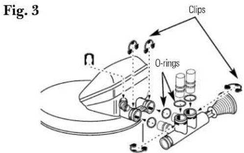
1 Install bypass valve:
- Remove plastic shipping plug and retainer from valve outlet.
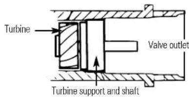
NOTE: Be sure the turbine and support are firmly in place, in the valve outlet. Blow into the valve port and observe the turbine for free rotation.
- Push the bypass valve (lubricate o-ring seals with silicone grease) into both ports of the valve as shown in Fig. 3.
IMPORTANT:
- Snap the 2 large plastic clips in place, as shown in Fig. 3. Be sure they snap into place. Pull on the bypass valve to make sure it is held securely in place.
2 Move the softener assembly into installation position:
CAUTION:
- Secure the resin tank to a stable structure to prevent it from falling over.
- Locate the brine tank directly next to the resin tank.
- Be sure the installation surface is level and smooth. Sharp objects under the brine tank may puncture it. If needed, place the brine tank on a section of 3/4" thick (minimum) plywood. Then, place shims under the plywood as needed to level the softener.
- Connect the black brine valve tube from the brinewell to the venturi assembly on the valve, using the plastic nut provided as shown in Fig. 5.
3 Plumb IN and OUT pipes to and from softener:
CAUTION: Observe all of the following cautions as you connect inlet and outlet plumbing.
- Be sure incoming hard water supply is directed to the softener valve inlet port. If house water flow is from the left, use a plumbing cross-over as shown in Fig. 1.
- Do all sweat soldering before connecting pipes to the bypass valve. Torch heat will damage plastic parts.
- When turning threaded pipe fittings onto plastic fittings, use care not to cross-thread.
- Use pipe joint compound on all external pipe threads.
- Support inlet and outlet plumbing in some manner (use pipe hangers) to keep the weight off of the valve fittings.
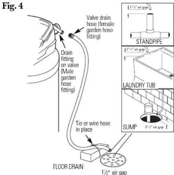
4 Connect and run the valve drain hose:
• Take a length of garden hose with female fitting and attach to the valve drain fitting, as shown in Fig. 4.
A IMPORTANT: Make sure the garden hose fitting fits securely onto the threaded drain port.
- Locate the other end of the hose at a suitable drain point (floor drain, sump, laundry tub, etc.) that terminates at the sewer drain. Check and comply with local codes.
A IMPORTANT: Use a high quality, thick-walled hose that will not easily kink or collapse. The water softener will not work if water cannot exit this hose during regenerations.
- Tie or wire the hose in place at the drain point. High water pressure will cause it to whip during the back-wash and fast rinse cycles of regeneration. Also provide an air gap of at least 1–1/2" between the end of the hose and the drain point. An air gap prevents possible siphoning of sewer water into the softener, if the sewer should back-up.
- If raising the drain hose overhead is required to get to the drain point, do not raise higher than 8' above the floor. Elevating the hose may cause a back-pressure that could reduce brine draw during regenerations.
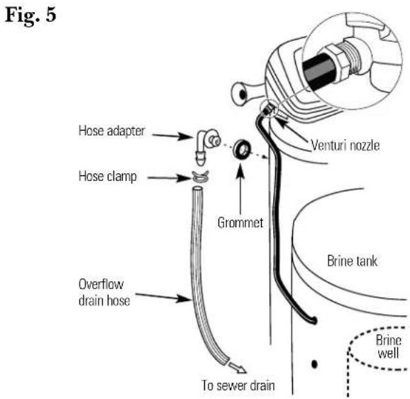
5 Install the brine tank overflow fittings and hose:
- Insert the rubber grommet into the 3/4" diameter hole in the brine tank sidewall as shown in Fig. 5.
- Push the end of the hose adapter elbow into the grommet as shown in Fig. 5.
- Attach a length of hose to the hose adapter elbow. Use a hose clamp to hold it in place.
- Locate the other end of the hose at the drain point. DO NOT ELEVATE this hose higher than the elbow on the brine tank.
IMPORTANT: DO NOT TEE OVERFLOW HOSE TO VALVE DRAIN HOSE.
NOTE: This drain is for safety only. If the cabinet (brine tank) should over-fill with water, the excess is carried to the drain.
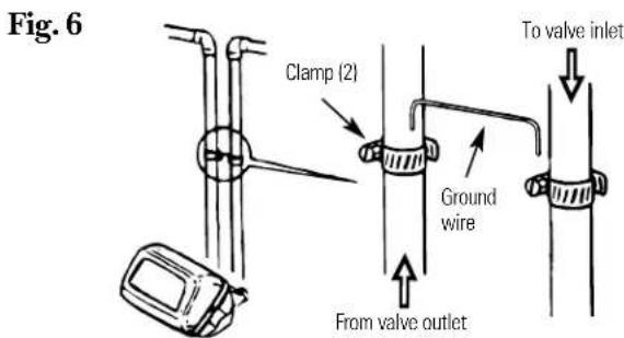
6 Install grounding clamps and wire:
DANGER: Failure to properly attach ground wire could result in electrical shock.
- If plumbing is metal, to maintain electrical ground continuity in the house cold water piping, install the included ground clamps as shown in Fig. 6. Be sure the pipes are clean under the clamps to assure good contact.
7 Flush pipes, expel air from softener, and test your installation for water leaks:
CAUTION: To avoid water or air pressure damage to softener inner parts, be sure to do the following steps in exact order.
A. Fully open 2 cold soft water faucets nearby the softener.
B. Place bypass valve in "bypass" position by pushing the stem inward.
C. Fully open the house main water pipe shutoff valve. Observe a steady flow from both faucets opened in Step A above.
D. Place bypass valve in the "service" position EXACTLY as follows. KEEP SOFT WATER FAUCETS OPEN.
SLOWLY pull or slide the valve stem (OUT) toward "service", pausing several times to allow the softener to pressurize slowly.
E. After about 3 minutes, open a HOT water faucet for 1 minute, or until all air is expelled, then close. NOTE: If water appears cloudy or has salty taste, allow to run for several more minutes or until clear.
F. Close all water faucets.
G. Check your plumbing work for leaks and fix right away if any are found. BE SURE TO OBSERVE PREVIOUS CAUTIONS.
8 Add water and salt to the brine tank:
- Lift the cabinet (brine tank) cover. Add about 3 gallons of water into the tank. Do not add into the brinewell.
- Fill tank 1 / 3 to 1 / 2 full with NUGGET, PELLET or coarse SOLAR water softener salt with a purity of 99.5% or higher. Do not use rock, block, granulated, or ice cream-making salts or salt with iron removing additives (except for Diamond Crystal® Red-Out® brand salt.)
NOTE: If the softener is installed in a humid basement or other damp area, it is better to fill the tank with less salt, more frequently. Eighty to 100 lbs. of salt will last for several months, depending on water hardness and family size.
9 Connect to electrical power:
- Using the instruction sheet provided with the electronic control, connect the wires from the valve to the electronic control.
- If transformer wiring is not visible at the back of the control head, remove control cover. DO NOT PULL ON OR DISCONNECT WIRING. Locate the long wire with U shaped connectors on one end. Route this wire through the rear of the control housing. Replace the control cover.
- Fasten the 2 power cable lugs ("U" shaped connectors) to the 2 screws on the transformer, and tighten the screws. Then, plug the transformer into the electrical outlet.
- The softener works on 24 volt-60 Hz electric power. The included transformer changes standard 120 volt AC house power to 24 volts. Plug the transformer into a 120 volt outlet only. Be sure the outlet is always live so it can not be switched off by mistake.
10 Program the control:
• See Programming the Control section.
Programming the Control
Timer settings required—upon installation and after an extended power outage.
NOTE:
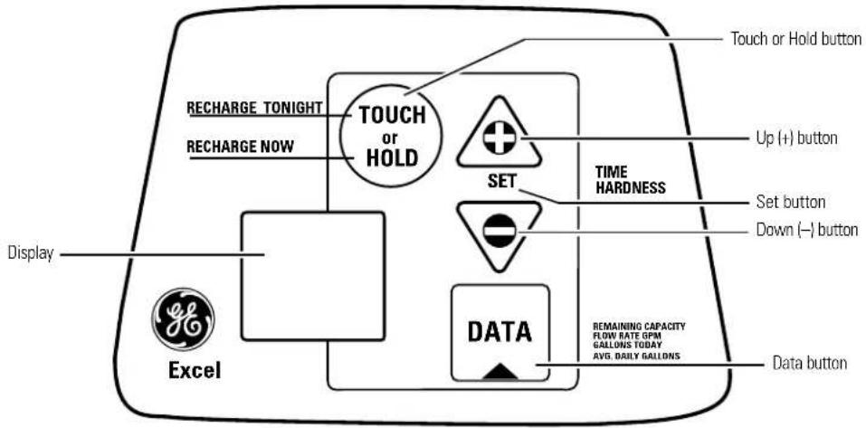
- When the transformer is plugged into the electrical outlet, 12:00 AM is flashing and the words PRESENT TIME show in the upper display area. Program the timer as instructed below. If, A---is flashing, see the Setting Model Code section.
- A beep sounds while pressing buttons for timer programming. One beep signals a change in the timer display. Repeated beeps means the timer will not accept a change from the button or arrow you have pressed and you should use another.
- To program the timer, you will use the SET, UP (+) and DOWN (-) buttons.
Set present time of day
NOTE: If the words PRESENT TIME do not show in the display, press the SET button until they do.
1 Press the UP (+) or DOWN (-) button to set. The UP button moves the display ahead; the DOWN button moves the time backward.
NOTE: Each press of an UP or DOWN button changes the time by 1 minute. Holding the buttons in changes the time 32 minutes each second.
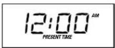
If the present time is between noon and midnight, be sure PM shows.
If the present time is between midnight and noon, be sure AM shows.
2 When the present time shows, press SET to apply.
Set water hardness number
NOTE: If 15 (factory default) and HARDNESS do not show in the display, press the SET button until they do.
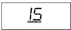
1 Press the UP (+) or DOWN (-) button to set your water hardness number in the display. The DOWN button moves the display down to 1. The UP button moves the display up to 110.
NOTE: Each press of an UP (+) or DOWN (-) button changes the display by 1 between 1 and 25. Above 25, the display changes 5 at a time (25, 30, 35, etc.). Holding a button in changes the numbers twice each second.
2 When your water hardness number shows, press SET to apply.
NOTE: If there is clear water iron in your water supply, you will need to increase the hardness setting by 5 for each 1 ppm of clear water iron in your water supply.
You can get the grains per gallon (gpg) hardness of your water supply from a water analysis laboratory, or call and ask your local water department, if you are on a municipal supply, or call GE Answer Center® to request a water hardness test kit. If your report shows hardness in parts per million (ppm) simply divide by 17.1 to get the equivalent number of grains per gallon.
Sanitizing Procedures
To complete the installation, do the following sanitizing procedures.
Care is taken at the factory to keep your water softener clean and sanitary. Materials used to make the softener will not infect or contaminate your water supply and will not cause bacteria to form or grow. However, during shipping, storage, installing and operating, bacteria could get into the softener. For this reason, sanitizing as follows is suggested when installing.
NOTE: Sanitizing is recommended by the Water Quality Association for disinfecting.
1 Be sure to complete all installation steps, including timer programming.
Pour about 3/4 oz. of common 5.25% household bleach (Clorox, Linco, Bo Peep, White Sail, Eagle, etc.) into the brinewell. Refer to illustration on page 8.
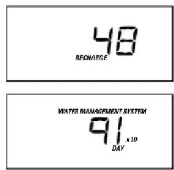
3 IMPORTANT: Press and hold for 3 seconds the faceplate TOUCH/HOLD button to start an immediate regeneration. Recharge Now begins to flash in the display. The bleach is drawn into and through the water softener.
4 If after sanitization water from house faucet tastes salty or has a slight color, this is a preservative from the resin tank. Turn on the cold soft water faucets and drain for a few minutes or until clear.
NOTE: When the above sanitizing regeneration is over, your house COLD water supply is fully soft immediately. However, your water heater is filled with hard water and as hot water is used, it will refill with soft water. When all the hard water is replaced in the water heater, hot only and mixed hot and cold water will be fully soft. If you want totally soft water immediately, after the above regeneration, drain the water heater until the water runs cold.
A WARNING: If you do drain the water heater, use extreme care as the hot water could cause burns. Turn the water heater off prior to draining.
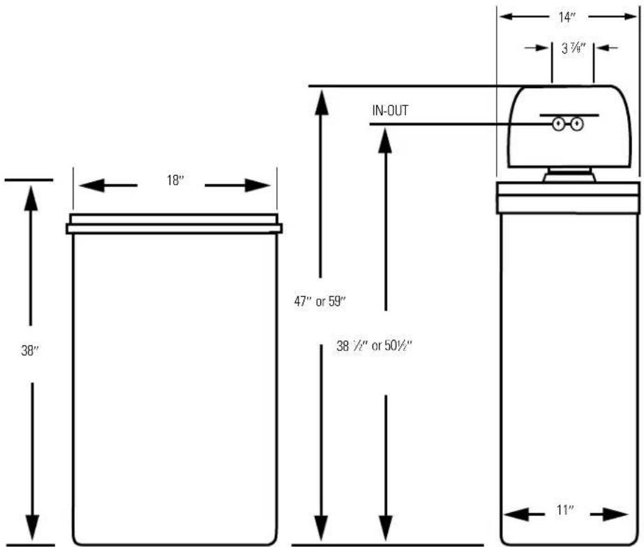
Specifications/Dimensions—See rating decal, located on the Water Softening System.
| Rated Capacity* | GNSF39A | GNSF48A |
| Amount of high capacity resin (lbs/cu. ft) | 54.6/1.05 | 67.6/1.30 |
| Resin tank nominal size (in., dia. x height) | 10" x 35" | 10" x 47" |
| Service flow rate (gpm) (see rating label on softener) | 12 | 12 |
| Water supply maximum hardness (gpg) | 110 | 110 |
| Water supply maximum clear water iron (ppm)** | 8 | 8 |
| Water pressure limits (min.-max. psi) | 20-125 | 20-125 |
| Pressure drop at rated service flow (psig) | 15 | 15 |
| Water temperature maximum (°F) | 120 | 120 |
| Water supply minimum flow rate (gpm) | 3 | 3 |
| Regeneration cycle flow rates (gpm) | ||
| Fill (flow to brinc tank) | .3 | .3 |
| Brining | .16 | .16 |
| Brine Rinse (flow to drain) | .12 | .12 |
| Backwash | 2.0 | 2.0 |
| Fast Rinse | 2.0 | 2.0 |
This system conforms to WQA S-100-98 for specific capacity claims as verified and substantiated by test data.
* Testing was performed using pellet grade sodium chloride as the regenerant salt.
** Extent of iron removal may vary with conditions. Use of Diamond Crystal® Red-Out® or Super Iron Out® will improve iron removal. Refer to Cleaning iron out of the Water Softening System section.
Service
When the water softening system is providing soft water, it is called “Service.” During service, hard water flows from the house main water pipe into the water softening system. Inside the water softening system resin tank is a bed made up of thousands of tiny, plastic resin beads. As hard water passes through the bed, each bead attracts and holds the hard minerals. This is called ion-exchanging. It is much like a magnet attracting and holding metals. Water without hard minerals (soft water) flows from the water softening system and to the house pipes.
After a period of time, the resin beads become coated with hard minerals and they have to be cleaned. This cleaning is called regeneration, or recharge. Regeneration is started at 2:00 AM (factory setting) by the water softening system control, and consists of five stages or cycles. These are FILL, BRINING, BRINE RINSE, BACKWASH and FAST RINSE.
Automatic Hard Water Bypass During Regeneration
For emergency needs, hard water is available to the home during the regeneration cycles.
However, you should avoid using HOT water because the water heater will fill with the hard water.
Fill
Salt dissolved in water is called brine. Brine is needed to clean the hard minerals from resin beads. To make the brine, water flows into the salt storage area during the fill stage.
Brining
During brining, brine travels from the salt storage area into the resin tank. Brine is the cleaning agent needed to remove hard minerals from the resin beads. The hard minerals and brine are discharged to the drain.
The nozzle and venturi create a suction to move the brine, maintaining a very slow rate to get the best resin cleaning with the least salt.
Brine Rinse
After a pre-measured amount of brine is used, the brine valve closes. Water continues to flow in the same path as during brining, except for the discontinued brine flow. Hard minerals and brine flush from the resin tank to the drain.
Backwash
During backwash, water travels up through the resin tank at a fast flow rate, flushing accumulated iron, dirt, and sediments from the resin bed and to drain.
Fast Rinse
Backwash is followed by a fast flow of water down through the resin tank. The fast flow flushes brine from the bottom of tank, and packs the resin bed.
After fast rinse, the water softening system returns to soft water service.
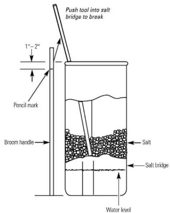
Breaking a Salt Bridge
Sometimes, a hard crust or salt bridge forms in the salt storage area. It is usually caused by high humidity or the wrong kind of salt. When the salt bridges, an empty space forms between the water and salt. Then salt will not dissolve in the water to make brine.
If the brine tank is full of salt, it is hard to tell if you have a salt bridge. Salt is loose on top, but the bridge is under it. The following is the best way to check for a salt bridge.
Salt should be loose all the way to the bottom of the tank. Take a broom handle or like tool, and carefully push it down into the salt, working it up and down. If the tool strikes a hard object (be sure it's not the bottom or sides of the tank), it's most likely a salt bridge. Carefully break the bridge with the tool. Do not pound on the walls of the tank.
If the wrong kind of salt made the bridge, take it out. Then fill the tank with nugget or pellet salt only. In humid areas, it is best to fill with less salt, more often.
Cleaning the Nozzle and Venturi Assembly
A clean nozzle and venturi is needed for the water softening system to work properly. This small unit makes the suction to move brine from the salt storage area to the resin tank during regeneration. If it becomes plugged with sand, dirt, etc., the water softening system will not work and you will get hard water.
To get to the nozzle and venturi, remove the water softening system top cover. Be sure the water softening system is in service cycle (no water pressure at nozzle and venturi). Then, while holding the nozzle and venturi housing with one hand, remove the cap. Lift out the screen support and screen, then the nozzle and venturi. Wash and rinse the parts in warm water until clean. If needed, use a small brush to remove iron or dirt. Also check and clean the gasket.
NOTE: Some models have a small flow plug located in the nozzle and venturi, and/or a small cone shaped screen in the housing. Be sure to check and clean these parts, if your model is so equipped.
Carefully replace all parts in the correct order. Lightly lubricate the o-ring seal with clean silicone grease or petroleum jelly and place in position. Install and tighten the cap, by hand only. Do not over-tighten the cap.
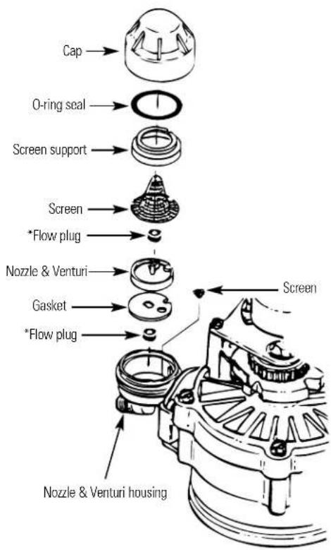
IMPORTANT: Be sure small holes in the gasket are centered directly over the small holes in the nozzle and venturi housing.
*Install with numbered side up, concave side down.
Normal Operation, Timer Display
During normal operation, the present time of day and AM or PM show in the control display area. When the demand computer determines a regeneration is needed, RECHARGE TONIGHT begins to flash in the display along with the present time. RECHARGE TONIGHT flashes until the next regeneration start time, then changes to RECHARGE NOW, which flashes until the regeneration is over. The display also shows the current cycle in the regeneration process. When the valve is in transition between cycles, both indicators flash.
Feature: Optional Recharge Controls
Sometimes, a manually started regeneration (recharge) may be desired or needed. Two examples:
■ You have used more water than usual (house guests, extra washing, etc.) and you may run out of soft water before the next regeneration.
■ You did not refill the storage tank with salt before it was all gone.
Use one of the following features to start a regeneration immediately, or at the next preset regeneration start time.
RECHARGE NOW
RECHARGE TONIGHT
RECHARGE NOW
TOUCH or HOLD
Press and hold the TOUCH or HOLD button until RECHARGE NOW starts to flash in the control display area. The water softening system begins an immediate regeneration and, when over in about two hours, you will have a new supply of soft water. Once started, you cannot cancel this regeneration.
RECHARGE TONIGHT
Touch (do not hold) the TOUCH or HOLD button. RECHARGE TONIGHT flashes in the control display area. A regeneration will occur at the next preset regeneration start time. If you decide to cancel this regeneration, touch the same button once more.
Feature: Program Memory
If electrical power to the water softening system is interrupted, the control display is blank, but the control keeps correct time for about 72 hours. When power is restored, you have to reset the present time only if the display is flashing. All other settings are maintained and never require resetting unless a change is desired.
If the time is flashing after a long power outage, the water softening system continues to work as it should to provide you with soft water. However, regenerations may occur at the wrong time of day until you reset the control to the correct time of day.
Feature/Service: Automatic Electronic Diagnostics
The timer computer has a self-diagnostic function for the electrical system (except input power and water meter). The computer monitors the electronic components and circuits for correct operation. If a malfunction occurs, an error code appears in the timer display.
The chart on Error Codes shows the error codes that could appear and possible defects for each code. While an error code is displayed, the TOUCH or HOLD and DATA buttons remain operable so you can perform the Manually Initiated Electronic Diagnostics.
| ERROR CODE DISPLAYED | ERR 01 ERR 02 ERR | 03 ERR 04 ERR | 05 | ||
| POSSIBLE DEFECT | → motor inoperative → wiring harness, or connection to switch→ position switch → valve defect causing high torque | → timer (PWA) | |||
To remove an error code: (1) Unplug transformer.
(2) Correct defect.
(3) Plug transformer in.
(4) Wait for at least 6 minutes. The error code will return if the reason for the error code was not corrected.

Feature: Other Data Displays
By continuing to press the DATA button, you can scan through four displays of operational information. This data appears in the bottom portion of the display area.
REMAINING CAPACITY — 97% This is the percentage of water softening capacity remaining. Immediately after a regeneration, 100% shows. As water is used, the percentage decreases until the next regeneration. During regenerations, the percentage increases.
NOTE: Zero (%) shows until after the first regeneration begins, after connecting to electrical power.
FLOW RATE, GPM—3.8 When using soft water, this display shows the flow rate passing through the softener (in gallons per minute). Zero shows if water is not passing through the softener.
GALLONS TODAY—Each day, beginning at midnight, the timer keeps a running count of the total gallons of water that have passed through the softener.
AVG. DAILY GALLONS—219 The figure displayed is the average gallons of water used by the household each day over the past seven day period.
NOTE: If preferred, you can set the timer to show the reading in liters instead of gallons. If GALLONS TODAY or AVG. DAILY GALLONS exceeds 1999, a (x10) indicator appears, this means you must multiply the number shown by ten.
Timer/Softener, Service Checkout Procedure
If you are not getting soft water, and an error code is not displayed, use the procedures below to find the problem. First make the following visual checks.
VISUAL CHECKS:
Is there electrical power to the outlet the water softening system transformer is plugged into?
2 Is there sufficient salt in the storage tank?
3 Is the plumbing bypass valve directing water for soft water service?
4 Is the valve drain hose open to the drain, not elevated too high, and unobstructed?
If you do not find a problem with the visual checks, continue below.
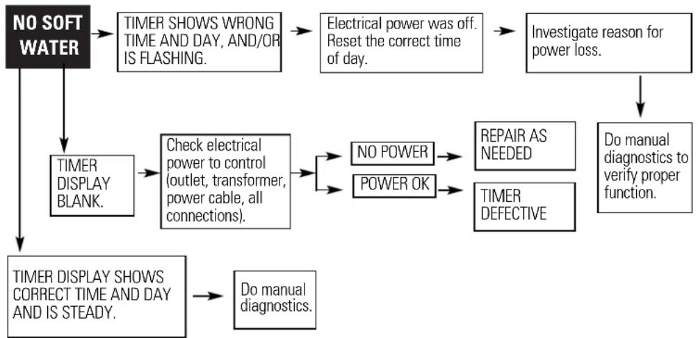
flowchart
graph TD
    A["NO SOFT WATER"] --> B["TIMER DISPLAY BLANK."]
    B --> C["Timer DISPLAY SHOWS CORRECT TIME AND DAY AND IS STEADY."]
    C --> D["Do manual diagnostics."]
    C --> E["Check electrical power to control (outlet, transformer, power cable, all connections)."]
    E --> F["NO POWER"]
    E --> G["POWER OK"]
    F --> H["REPAIR AS NEEDED"]
    G --> I["TIMER DEFECTIVE"]
    H --> J["Do manual diagnostics to verify proper function."]
    I --> J
    K["INVESTIGATE REASON FOR POWER LOSS."] --> J
    L["TIMER SHOWS WRONG TIME AND DAY, AND/OR IS FLASHING."] --> M["Electrical power was off. Reset the correct time of day."]
    M --> N["No POWER"]
    M --> O["POWER OK"]
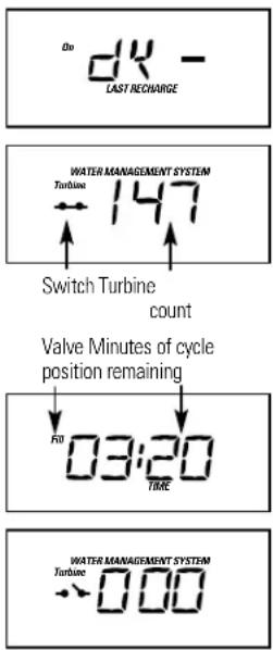
Service: Manually Initiated Electronic Diagnostics
To enter diagnostics, press and hold the DATA button until the display appears as shown.
NOTE: If the softener is in the middle of a regeneration, top part of the display shows the cycle of regeneration and minutes of the cycle remaining. If two cycle names are flashing, the valve is in transition between the cycles.
A The three digits under WATER MANAGEMENT SYSTEM indicate water meter operation as follows:
■ 000 (steady) = soft water not in use...no flow through the meter.
—OPEN A NEARBY SOFT WATER FAUCET—
■ 000 to 140 (continual) = repeats display for each gallon of water passing through the meter.
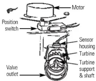
If you don't get a reading in the display, with faucet open, pull the sensor from the valve outlet port. Pass a small magnet back and forth in front of the sensor. You should get a reading in the display. If you get a reading, shut off water supply, unhook the in and out plumbing and check the turbine for binding.
B This display segment ( ), in the following chart, indicates an open POSITION switch. Use the TOUCH or HOLD button to manually advance the valve into each cycle and check correct switch operation.
| CORRECT SWITCH DISPLAYS VALVE CYCLE STATUS | |
| Valve in service, fill, brining, backwash or fast rinse position. | |
| Valve rotating from one position to another. | |
2 Press the DATA button again. This diagnostic display shows the total number of recharges (top) since the timer was connected to electrical power.
The number of days since the timer was connected to electrical power is shown in the bottom part of the display. If over 1999 days, a (x10) indicator shows, meaning you must multiply the number shown by 10.
3 Press DATA once again to return the present time to the display.
Service: Manually Advance Regeneration Check
This check verifies proper operation of the valve motor, brine tank fill, brine draw, regeneration flow rates and other controller functions. First, make the initial checks and the manually initiated electronic diagnostics.
NOTE: The face plate display must show a steady time (not flashing).
1 Press the TOUCH or HOLD button and hold for three seconds. RECHARGE NOW begins to flash as the water softening system enters the fill cycle of regeneration. Remove the brinewell cover and, using a flashlight, observe fill water entering the brine tank.
If water does not enter the tank, look for an obstructed nozzle, venturi, fill flow plug, brine tubing, or brine valve riser pipe.
2 After observing fill, press the TOUCH or HOLD button to move the water softening system into brining. A slow flow of water to the drain will begin. Verify brine draw from the brine tank by shining a flashlight into the brinewell and observing a noticeable drop in the liquid level.
NOTE: Be sure a salt bridge is not preventing salt contact with water.
If the water softening system does not draw brine, check:
■ nozzle and/or venturi dirty or defective.
■ nozzle and venturi not seated properly on gasket.
■ restricted drain (check drain fitting and hose).
■ defective nozzle and venturi seal.
■ other inner valve defect (rotor seal, rotor & disc, wave washer, etc.).
NOTE: If water system pressure is low, an elevated drain hose may cause back pressure, stopping brine draw.
3 Again, press the TOUCH or HOLD button to move the softener into backwash. Look for a fast flow of water from the drain hose.
A slow flow indicates a plugged top distributor, backwash flow plug, or drain hose.
4 Press TOUCH or HOLD to move the water softening system into fast rinse. Again look for a fast drain flow. Allow the water softening system to rinse for a few minutes to flush out any brine that may remain in the resin tank from the brining cycle test.
5 To return the water softening system to service, press TOUCH or HOLD.
Service: Regeneration and Heavy Duty Backwash
NOTE: Each of the following functions has a factory set default value. The defaults are: Regeneration start time -2:00AM; Maximum days between regenerations -0 (display shows dY-); Heavy duty backwash -OFF. The defaults are suitable for most installations. However, depending on water supply quality, household peak water use hours, etc., adjustment is available to meet specific needs. To make a change, read and do the following.
Regeneration (Start) Time: At the 2:00 AM regeneration start time, the water softening system begins regeneration at that time, ending at about 4:00 AM. This is a good time in most households because water is not in use (see Automatic Hard Water Bypass During Regeneration section). If a different time would be better for your needs, do steps 1, 2, 3, 5, 7, 8 and 9 below to change the starting hour.
Maximum Days Between Regeneration: The default setting (dY-) allows the timer to control regeneration frequency based on water usage readings from the water meter. It provides the most economical operation. You can set a maximum time (in days) between regenerations. For example, no more than three days will pass without a regeneration occurring if you set dY 3 in the display. A 1 to 7 day setting is available. To make a change from the default setting, do steps 1, 2, 3, 5, 7, 8 and 9 below.
Heavy Duty Backwash: When set to ON, the backwash cycle of regeneration will be 10 minutes long instead of the normal seven minute length. This is beneficial on some water supplies high in iron or sediment content. To conserve water, on clean supplies, be sure the default setting OFF shows. To change this setting, do steps 1, 2, 3, 5, 7, 8 and 9 below.
Auto Regeneration When Capacity is Low: The softener will regenerate at the regeneration time only. Although the control has a look-forward feature which anticipates normal demand, an unusually high usage may result in a loss of softening capacity. Turning the feature ON will cause the softener to go into a regeneration cycle when 97% of the softening capacity has been used. To change settings do steps 1, 3, 5, 7, 8 and 9.
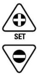
1 Beginning from the present time display, press and hold in the SET button until begins to flash.
2 Press the UP or DOWN button to display the desired start time. The UP button moves the time ahead; the DOWN button moves the time backward.
3 Press the SET button again, and flashes.
4 To set a maximum time (in days) between regenerations, press the UP or DOWN button.
5 Press the SET button to display =OFF
6 Use the UP button to change the display to ON to increase the backwash time, if desired.
7 Press the SET button =OFF and 97 alternately flashes.
8 Use the UP button to turn Auto Regeneration cycle to ON.
9 Press the SET button a final time to return to present time of day.
Setting: Model Code, 12 or 24 Hour Clock and Gallons or Liters Measured
Model Code: The timer must have the right model code set to operate the water softening system correctly. The correct code setting for the GNSF39A is A-31. The correct code setting for the GNSF48A is A-39.
If is flashing in the display, do steps 3, 4, 6 and 8 below.
To check for the correct code setting for your model, and to reset it if needed, do steps 1, 2, 3, 4, 6 and 8 below.
NOTE: The hour clock and water measure have factory set default values. The defaults are: 12 or 24 hour clock -12; Gallons or liters measure — gallons.
12 or 24 Hour Clock: With 12 hr set, all time displays are in standard clock time ...12:00 AM to 11:59 PM. If 24 hr is set, time displays are in military time ...0100 (1:00 AM) to 0000 (midnight). To change from the 12 hr setting, do steps 1, 2, 4, 5, 6 and 8.
Gallons or Liters Measure: All water flow rate and usage displays are in gallons with the default GALS setting. If reset to, the same displays are shown in liters. Use steps 1, 2, 4, 6, 7 and 8 to change.
Beginning from the present time display, press and hold in the SET button until (or as otherwise set) begins to flash.
2 Press and hold in the SET button again.
3 If setting is other than A-31 (for the GNSF39A) or A-39 (for the GNSF48A) use the UP or DOWN button to set the correct number.
4 Press the SET button again and flashes.
5 To change the display to use the UP button. Use the DOWN button to reset to 12 hr.
6 Press the SET button and flashes
7 Use the UP button to change to the setting. Use the DOWN button to return to the gallon setting.
8 Press the SET button a final time to return to the present time display.
Checking the Salt Storage Level and Refilling
Brine (salt dissolved in water) is needed for each and every regeneration. The water for making brine is metered into the salt storage area by the water softening system valve and control. However, you must keep the tank supplied with salt.
When to refill with salt: Check the salt level a few weeks after you install the water softening system and every week after that. Refill when the brine tank is from 1/3 to 1/2 full. Never allow the water softening system to use all the salt before you refill it. Without salt, you will soon have hard water.
Use clean water softening salts only, at least 99.5% pure. NUGGET, PELLET or coarse SOLAR salts are recommended. Do not use rock, block, granulated or ice cream making salts. They contain dirt and sediments, or mush and cake, and will create maintenance problems.
CAUTION: Water softening salt with iron removing additives: Some salts may have an additive to help the water softening system handle iron in the water supply. Although this additive may help to keep the water softening system resin clean, it may also release corrosive fumes that weaken and shorten the life of some water softening system parts. GE recommends using only Diamond Crystal® Red•Out® brand salt.
Cleaning Iron Out of the Water Softening System
Your water softening system takes hardness minerals (calcium and magnesium) out of the water. Also, it can control some (see Specification Guidelines section) “clear water” iron. With clear water iron, water from a faucet is clear when first put into a glass. After 15 to 30 minutes, the water begins to cloud or turn rust colored.
A water softening system will not remove any iron that makes the water cloudy or rusty as it comes from the faucet (called red water iron). To take red water iron out of water, or over the maximum of clear water iron, an iron filter or other equipment is needed.
GE recommends using only Diamond Crystal® Red-Out® brand salts with Iron Fighter® additive to help keep the resin bed clean of clear iron. If your water supply has clear water iron, periodic resin bed cleaning is needed. GE recommends using Super Iron Out® brand resin bed cleaner to thoroughly clean your resin bed if your iron content is high. Clean the bed at least every six months, or more often if iron appears in the soft water between cleanings.
IMPORTANT: It is important to mix the resin bed cleaner with water (following the manufacturer's instructions), pour it into the brine well (see page 6) and regenerate the softener immediately. Do not pour the resin bed cleaner in with the salt, as it will not be as effective in cleaning the resin, and can cause damage to the softener if it is left in the brine tank for an extended period due to the corrosive gases that are formed.

Troubleshooting Tips Save time and money! Review the chart on this page first and you may not need to call for service.
NO SOFT WATER – Most Common Problems:
Check the following before calling for service
- Salt in softener...at least 1/3 full.
- By pass valve in "Service" position. Knob should be in the OUT position.
- Check hardness setting in control. Verify hardness of supply water. Water hardness can vary throughout the year (see Programming the Control section).
- Salt Bridge, water not in contact with salt (see Breaking a Salt Bridge section).
Problem Possible Causes What To Do
| No soft water | Faucet or fixture where sample was• taken not plumbed to soft water.NOTE:Be sure sample is from a faucet that does not mix soft and hard water. For example, a single lever kitchen faucet, if the cold side is plumbed to hard water | To conserve salt, the installer may have isolated some fixtures (outside faucets, toilets, etc.) from soft water. From the outlet of the water softening system, trace the water flow path, in house plumbing. If soft water is not directed to a faucet or fixture where wanted, consult a plumber. |
| No salt in the brine tank or salt bridged recommended salt. Press (for 3 seconds) the button to start an immediate regeneration and restore soft water supply. | •Check for a salt bridge or, if the tank is empty, refill with TOUCH or HOLD | |
| Transformer unplugged at wall outlet or power cable to softener not connected. Fuse blown or circuit breaker popped on circuit to electrical outlet. Electrical outlet on a circuit that can be switched off. | •Check for a loss of electrical power to the water softening system, due to any of these conditions and correct as needed. With the power supply restored, observe the faceplate time display and read Program Memory section.NOTE:The electrical outlet for the softener should be continuously live so it cannot be accidentally switched off. | |
| Manual bypass valve in bypass position | •Be sure the bypass valve stem is positioned properly, with the knob in the OUT position. Observe instructions on the decal at the end of the stem. | |
| Valve drain hose pinched, plugged,• elevated too high or otherwise restricted during regenerations. | Any restriction in this drain hose may prevent proper operation of the nozzle and venturi and reduce or prevent brine draw | |
| Nozzle and venturi dirty, incorrectly•Refer to assembled or damaged | Cleaning the Nozzle and Venturi Assembly instructions. With water pressure to the water softening system off, take the nozzle assembly apart. Inspect, clean and replace as needed. Any foreign particle(s), scratches, nicks, etc., in the passages can prevent operation. Be sure holes in the gasket are centered over holes in the housing. |

Troubleshooting Tips
Problem Possible Causes What To Do
| Water hard sometimes | Using hot water while the water softening system is regenerating | ●Avoid using hot water during water softening systemregenerations because the water heater will refill withhard water. SeeAutomatic Hard Water Bypass DuringRegenerationsection. |
| Control hardness number setting •Press and release the too low display. Be sure the number shown is the same as the actualgrains per gallon hardness of your water supply. See theControlsection if a change in the setting is needed. | ||
| Grains of hardness in your water •supply have increased To check, have the water tested by a water analysis laboratoryor call your local water department. Adjust the hardnessnumber setting as needed. | ||
| Water feels slippery after installation of water softening system | Absence of hardness minerals •This is normal. | |
| Water softening system not using any salt | Water softening system is a “demand” unit | ●Docs not use much salt to regenerate—very efficient. |
| Possible salt bridge •See the | Operating Instructions,Tipssection. | |
| Possible plugged nozzle and venturi | ●See the Operating Instructions,Tipssection. | |
| Water is blue color after water softening system was installed | Acidic water in copper plumbing | ●Have the water tested at once.▲WARNING: Do not drink the water until problem has been corrected. |
| Water softening system not regenerating | Meter turbine stuck | ●Call for service. |
| Sensor wire corroded | ●Call for service. | |
| No power to unit | ●Check the circuit breaker or fuses. | |
| Mechanical defect | ●Call for service. | |
| Cloudiness on glassware (automatic dishwashers) | Combination of soft water and too much detergent | ●This is called etchingand is permanent. To prevent this from happening, use less detergent if you have soft water.Wash glassware in the shortest cycle that will get them clean. |
| Problem Possible Causes What To Do | ||
| Salty tasting water after installation | Insufficient backwash and rinse time | •Increase backwash time. See the Service: Regeneration and Heavy Duty Backwash section. |
| Low water pressure | •Check pressure; should be minimum 20 psi. | |
| Restricted drain hose •Clean and reconnect hose. | ||
| Resin beads showing up in drinking water and sink | Cracked distributor •Call for service. | |
| Sounds you might hear | Running water from the unit into •This is normal.a drain | |
| Water has air bubbles and is cloudy | Air in system after installation | •Will go away after it runs for a while. |
| Error Code on control | Wiring may have worked loose •Unplug transformer.in control | •Remove control cover, release clips on side.•Check for loose/incorrect wiring connections to electronic board or switch. Reconnect as required.•Reassemble control cover.•Plug in Transformer.•Wait six minutes for Error Code to reappear.•If Error Code reappears call for service. |
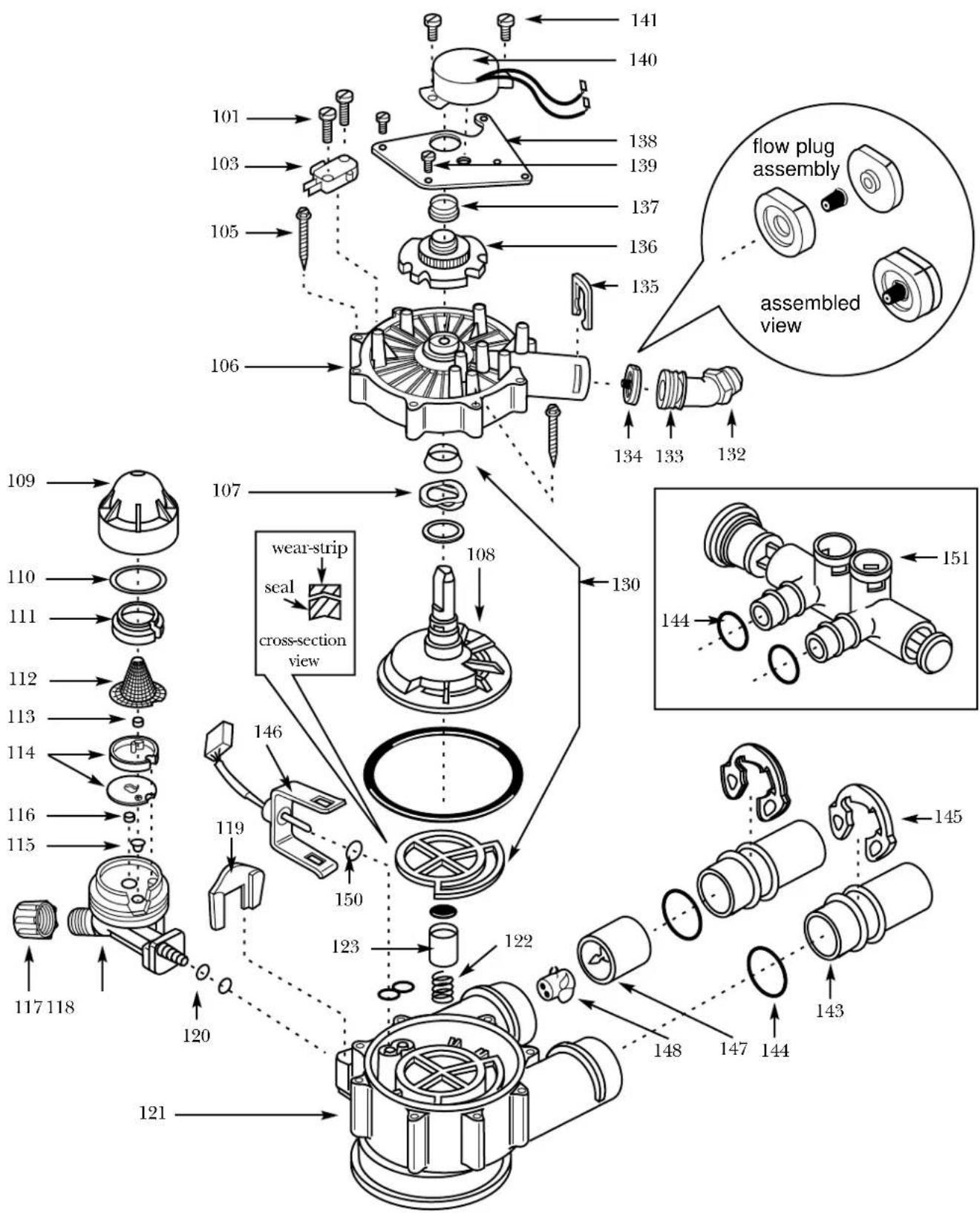
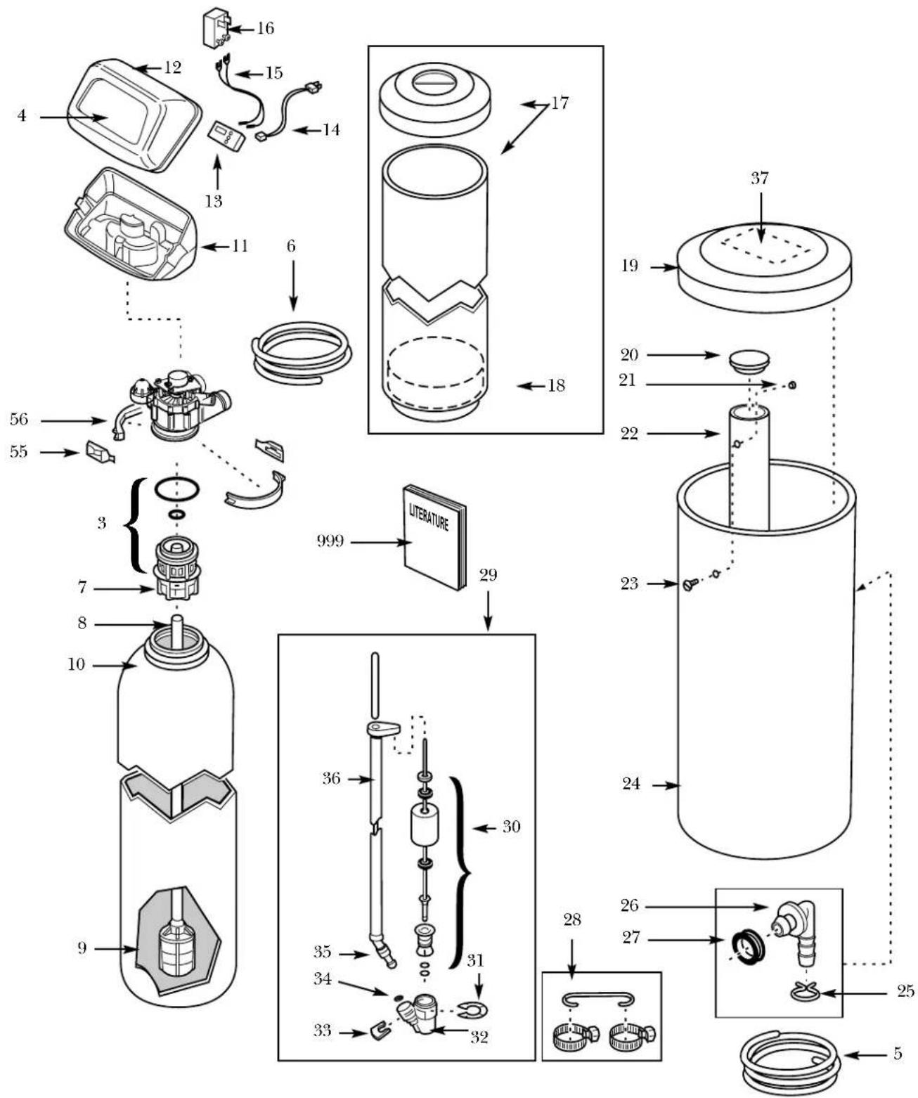
REF. #. CAT. #. PART DESCRIPTION GNSF39 GNSF48
| 3 WS35X10001 O-RING SEAL KIT 1 1 | ||||
| 4 WS34X10006 DECAL 1 1 | ||||
| 5 WS07X10004 OVERFLOW DRAIN HOSE -20 FT 1 1 | ||||
| 6 WS07X10012 VALVE DRAIN HOSE -15 FT 1 1 | ||||
| 7 WS14X10002 DISTRIBUTOR TOP 1 1 | ||||
| 8 WS14X10001 DISTRIBUTOR BOTTOM 1 1 | ||||
| 9 WS01X10003 RESIN - 1/2 CU. FT. 1 1 | ||||
| 9 WS01X10002 RESIN - 1 CU. FT. 1 1 | ||||
| 10 | WS32X10004 | TANK RESIN -10" x 35" | 1 | - |
| 10 | WS32X10014 | TANK RESIN -10" x 47" | - | 1 |
| 11 WS31X10015 COVER BOTTOM 1 1 | ||||
| 12 WS31X10014 COVER FACEPLATE | 1 1 | |||
| 13 WS21X10009 TIMER | 1 1 | |||
| 14 WS06X10003 HARNESS WIRE | 1 1 | |||
| 15 WS06X10004 POWER CORD | 1 1 | |||
| 16 WS26X10001 TRANSFORMER | 1 1 | |||
| 17 WS31X10016 SHROUD AND BASE | 1 | 1 | ||
| 18 WS33X10004 BASE | 1 1 | |||
| 19 WS33X10005 COVER, BRINE TANK | 1 1 | |||
| 20 WS31X10017 COVER, BRINEWELL | 1 1 | |||
| 21 WS02X10021 NUT, #6-32 | 1 1 | |||
| 22 WS32X10002 BRINEWELL | 1 1 | |||
| 23 WS02X10022 SCREW #6-32 | 1 1 | |||
| 24 WS32X10013 TANK BRINE | 1 1 | |||
| 25 WS18X10003 CLAMP HOSE | 1 1 | |||
| 26 WS22X10016 ADAPTOR HOSE 1 | 1 | |||
| 27 WS22X10017 GROMMET | 1 1 | |||
| 28 WS01X10005 HOSE CLAMP | 2 2 | |||
| 28 WS01X10006 GROUND WIRE | 1 1 | |||
| 29 WS15X10005 BRINE VALVE ASM. 1 | 1 | |||
| 30 WS35X10003 FLOAT, STEM AND GUIDE ASM. | 1 1 | |||
| 31 WS03X10006 CLIP | 1 1 | |||
| 32 WS15X10006 VALVE BODY, BRINE | 1 1 | |||
| 33 WS03X10007 CLIP | 1 1 | |||
| 34 WS03X10008 SCREEN | 1 1 | |||
| 35 | WS07X10002 | TUBING ASM. | 1 | 1 |
| 36 WS07X10003 TUBE BRINE | 1 1 | |||
| 37 WS34X10007 DECAL 1 1 | ||||
| 55 WS28X10003 RETAINER CLAMP | 2 2 | |||
| 56 WS28X10007 CLAMP | 1 1 | |||
| 101 | WS02X10023 SCREW, #4-24 x 3/4 | 2 2 | ||
| 103 | WS21X10008 SWITCH | 1 | 1 | |
| 105 | WS02X10024 SCREW, #10 x 2 5/8 | 8 8 | ||
| 106 | WS31X10013 COVER VALVE | 1 1 | ||
| 107 | WS03X10034 WASHER WAVE | 1 | 1 | |
| 108 | WS26X10010 ROTOR AND DISC | 1 | 1 | |
| 109 | WS19X10010 | CAP | ||
| 110 | WS03X10011 | SEAL O-RING 1-1/8" x 1-3/8" | 1 | 1 |
| 111 | WS19X10005 SUPPORT SCREEN | 1 | 1 | |
| 112 | WS03X10013 SCREEN | 1 1 | ||
| 113 | WS22X10020 FLOW PLUG, .1 GPM | 1 | 1 | |
| 114 | WS08X10006 GASKET, NOZZLE/VENT | 1 1 | ||
| 115 | WS03X10015 SCREEN CONE | 1 1 | ||
REF. #. CAT. #. PART DESCRIPTION GNSF39 GNSF48
| 116 WS22X10021 PLUG, FILL FLOW, .3 GPM 1 1 | ||||
| 117 WS03X10017 NUTFERRULE 1 1 | ||||
| 118 WS15X10027 NOZZLE/VENTURI ASM. 1 1 | ||||
| 119 WS03X10018 RETAINER 1 1 | ||||
| 120 | WS03X10019 | SEAL, O-RING 1/4" x 3/8" | 2 | 2 |
| 121 WS15X10025 BODYVALVE 1 1 | ||||
| 122 WS03X10020 SPRING 1 1 | ||||
| 123 WS22X10029 PLUG, DRAIN SEAL 1 1 | ||||
| 130 WS35X10020 SEAL KIT 1 1 | ||||
| 132 WS22X10030 ADAPTOR, DRAIN HIOSE 1 1 | ||||
| 133 | WS03X10025 | SEAL, O-RING 15/16" x 1-3/16" | 1 | 1 |
| 134 WS03X10035 PLUG FLOW | 1 1 | |||
| 135 WS03X10033 CLIP, DRAIN | 1 1 | |||
| 136 WS26X10008 CAM AND GEAR | 1 1 | |||
| 137 WS26X10009 BEARING | 1 1 | |||
| 138 WS26X10007 PLATE MOTOR | 1 1 | |||
| 139 | WS02X10015 | SCREW, #6-20 x 3/8" | 3 | 3 |
| 140 WS26X10006 MOTOR ASM. | 1 1 | |||
| 141 | WS02X10016 | SCREW, #6-20 x -7/8" | 2 | 2 |
| 143 WS60X10007 TUBE INSTALLATION | 2 2 | |||
| 144 | WS03X10037 | O-RING 1-1/8" x 1-3/8" | 4 | 4 |
| 145 WS60X10008 CLIP | 2 2 | |||
| 146 WS28X10009 HOUSING SENSOR | 1 1 | |||
| 147 WS19X10008 TURBINE SUPPORT | 1 1 | |||
| 148 WS19X10009 TURBINE | 1 1 | |||
| 150 WS03X10024 SEAL, O-RING | 1 1 | |||
| 151 WS15X10026 VALVE BY-PASS ASM. | 1 1 | |||
| 998 WS35X10021 INSTALL KIT -GNSF39Z/GNSF48Z | 1 1 | |||
| 999 | 49-50020-3 | PM MANUAL USE & CARE/INSTALLATION | 1 | 1 |
*NOTE: Codes in the State of Massachusetts require installation by a licensed plumber and do not permit the use of the saddle valve. For installation, use plumbing code 248-CMR of the Commonwealth of Massachusetts.
GE Service Protection Plus™
GE, a name recognized worldwide for quality and dependability, offers you Service Protection Plus™—comprehensive protection on all your appliances—No Matter What Brand!
Benefits Include:
- Backed by GE
- All brands covered
• Unlimited service calls - All parts and labor costs included
• No out-of-pocket expenses
• No hidden deductibles
• One 800 number to call
We'll Cover Any Appliance. Anywhere. Anytime.\*
You will be completely satisfied with our service protection or you may request your money back on the remaining value of your contract. No questions asked. It's that simple.
Protect your refrigerator, dishwasher, washer and dryer, range, TV, VCR and much more—any brand! Plus there's no extra charge for emergency service and low monthly financing is available. Even icemaker coverage and food spoilage protection is offered. You can rest easy, knowing that all your valuable household products are protected against expensive repairs.
Place your confidence in GE and call us in the U.S. toll-free at 800-626-2224 for more information.
*All brands covered, up to 20 years old, in the continental U.S.
Please place in envelope and mail to:
General Electric Company
Warranty Registration Department
P.O. Box 32150
Louisville, KY 40232-2150
Consumer Product Ownership Registration
Dear Customer:
Thank you for purchasing our product and thank you for placing your confidence in us.
We are proud to have you as a customer!
Follow these three steps to protect your new appliance investment:
1
Complete and mail
your Consumer
Product Ownership
Registration today.
Have the peace of
mind of knowing we
can contact you in the
unlikely event of a
safety modification.
2
After mailing the
registration below,
store this document
in a safe place. It
contains information
you will need should
you require service.
Our service number is
800 GE CARES
(800-432-2737).
3
Read your Owner's
Manual carefully.
It will help you
operate your new
appliance properly.
If you have questions,
or need more
information, call the
GE Answer Center®
800.626.2000.
Model Number Serial Number

natural_image
Two identical horizontal lines with tick marks, no text or symbols presentImportant: If you did not get a registration card with your product, detach and return the form below to ensure that your product is registered, or register online at www.geappliances.com.

Consumer Product Ownership Registration

Model Number Serial Number

natural_image
Two identical horizontal lines with tick marks, no text or symbols presentMr. □ Ms. □ Mrs. □ Miss □
First Name
Last Name
Street Address
Apt. #
E-mail Address
City State Zip Code
Date Placed
In Use Month
(No text)
Day
Year
Phone Number
Occasionally, we may allow selected companies to send you information.
☐ Check here if you do not want this information.

GE Appliances
General Electric Company
Louisville, Kentucky
www.geappliances.com

All warranty service provided by our Factory Service Centers, or an authorized Customer Care® technician. For service, call 800-GE-CARES.
For The Period Of: GE Will Replace:
| One Year Any partFrom the date of the original purchase | of the Water Softening System which fails due to a defect in materials or workmanship.During thisfull one-year warranty, GE will also provide,free of charge, all labor and in-home service to replace the defective part. | |
| Three Years The electronic monitor,From the date of thethree-year limited warranty,original purchase | if it fails due to a defect in materials or workmanship. During thisyou will be responsible for any labor or in-home service costs. | |
| Ten Years A replacement brine tank or cabinet,From the date of theoriginal purchase | During thisten-year limited warranty, you will be responsible for any labor or in-home service costs. | |
What GE Will Not Cover:
■ Service trips to your home to teach you how to use the product.
■ Improper installation.
■ Failure of the product if it is abused, misused, or used for other than the intended purpose or used commercially.
■ Filters, membranes or batteries.
■ Replacement of house fuses or resetting of circuit breakers.
■ Damage to the product caused by accident, fire, floods or acts of God.
■ Incidental or consequential damage to personal property caused by possible defects with this appliance.
This warranty is extended to the original purchaser and any succeeding owner for products purchased for home use within the USA. In Alaska, the warranty excludes the cost of shipping or service calls to your home.
Some states do not allow the exclusion or limitation of incidental or consequential damages. This warranty gives you specific legal rights, and you may also have other rights which vary from state to state. To know what your legal rights are, consult your local or state consumer affairs office or your state's Attorney General.
Warrantor: General Electric Company. Louisville, KY 40225
GE Answer Center ^® 800.626.2000
The GE Answer Center ^® is open 24 hours a day, 7 days a week.
OR
Visit our website at: www.geappliances.com.

In-Home Repair Service 800-GE-CARES (800-432-2737)
Expert GE repair service is only a phone call away.

Special Needs Service 800.626.2000
800-TDD-GEAC (800-833-4322)
GE offers, free of charge, a brochure to assist in planning a barrier-free kitchen for persons with limited mobility.

Service Contracts 800-626-2224
Purchase a GE service contract while your warranty is still in effect and you'll receive a substantial discount. GE Consumer Service will still be there after your warranty expires.
Parts and Accessories 800-626-2002
Individuals qualified to service their own appliances can have parts or accessories sent directly to their homes (VISA, MasterCard and Discover cards are accepted).
Instructions contained in this manual cover procedures to be performed by any user. Other servicing generally should be referred to qualified service personnel. Caution must be exercised, since improper servicing may cause unsafe operation.

Service Satisfaction
If you are not satisfied with the service you receive from GE:
First, contact the people who serviced your appliance.
Next, if you are still not pleased, write all the details—including your phone number—to:
Manager, Customer Relations
GE Appliances
Appliance Park
Louisville, KY 40225