
VW-SP1X44K - Processor KanexPro - Free user manual and instructions
Find the device manual for free VW-SP1X44K KanexPro in PDF.

| Product Type | 1x4 HDMI 4K UHD Video Wall Processor with Bezel Correction |
| Brand | KanexPro |
| Model | VW-SP1X44K |
| Input Ports | 1 x HDMI (female), 1 x Control (RJ45), 1 x RS-232 (D-sub 9-pin), 1 x USB (service only) |
| Output Ports | 4 x HDMI (female) |
| Video Bandwidth | 300 MHz / 9 Gbps |
| Supported Resolutions (Input) | VGA to WUXGA, 480i to 1080p, 4K2K@24/25/30 Hz |
| Supported Resolutions (Output) | 640x480 to 1920x1200 (RB), 1080p, 4K2K@24/25/30 (with limitations) |
| Audio Support | AC3, DTS, Dolby Digital Plus, Dolby TrueHD, Dolby Atmos, DTS-HD Master Audio, LPCM up to 7.1ch @192kHz |
| Video Wall Configuration | 1x1 to 15x15 (manual rows/columns), up to 3x3 cascaded units, hotkeys for common layouts (2x2, 3x3, etc.) |
| Bezel Correction | Adjustable horizontal and vertical bezel compensation (0-255), enable/disable via command or software |
| Control Methods | RS-232 (115200 baud, 8N1) and Telnet (Ethernet) with PC application |
| HDCP Compliance | Yes |
| Power Supply | 12 V / 3 A DC (locking connector), included |
| Power Consumption | 12.98 W |
| Dimensions (Jacks Excluded) | 438 mm (W) x 269 mm (D) x 44 mm (H) |
| Dimensions (Jacks Included) | 482 mm (W) x 274 mm (D) x 52 mm (H) |
| Weight | 2956 g |
| Chassis Material | Metal |
| Color | Black |
| Rack Mountable | Yes, 1U (19") rack mountable enclosure |
| Operating Temperature | 0°C to 40°C (32°F to 104°F) |
| Storage Temperature | -20°C to 60°C (-4°F to 140°F) |
| Relative Humidity | 20% to 90% RH (non-condensing) |
| Warranty | 3-year parts and labor (by KanexPro) |
Frequently Asked Questions - VW-SP1X44K KanexPro
User questions about VW-SP1X44K KanexPro
0 question about this device. Answer the ones you know or ask your own.
Ask a new question about this device
Download the instructions for your Processor in PDF format for free! Find your manual VW-SP1X44K - KanexPro and take your electronic device back in hand. On this page are published all the documents necessary for the use of your device. VW-SP1X44K by KanexPro.
USER MANUAL VW-SP1X44K KanexPro
1×4 HDMI 4K UHD Video Wall Processor with Bezel Correction
Create Video Walls from 2x2, 2x3 & 3x3 screens up to 9-Displays
All Rights Reserved
MPN: VW-SP1X44K
SAFETY PRECAUTIONS
Please read all instructions before attempting to unpack, install or operate this equipment and before connecting the power supply.
Please keep the following in mind as you unpack and install this equipment:
- Always follow basic safety precautions to reduce the risk of fire, electrical shock and injury to persons.
- To prevent fire or shock hazard, do not expose the unit to rain, moisture or install this product near water.
• Never spill liquid of any kind on or into this product. - Never push an object of any kind into this product through any openings or empty slots in the unit, as you may damage parts inside the unit.
• Do not attach the power supply cabling to building surfaces. - Use only the supplied power supply unit (PSU). Do not use the PSU if it is damaged.
- Do not allow anything to rest on the power cabling or allow any weight to be placed upon it or any person to walk on it.
- To protect the unit from overheating, do not block any vents or openings in the unit housing that provide ventilation and allow for sufficient space for air to circulate around the unit.
CONTENTS
- Introduction ...... 1
- Applications .... 1
- Package Contents .... 1
- System Requirements .... 1
- Features.... 2
- Operation Controls and Functions...... 2
6.1 Front Panel....2
6.2 Rear Panel....3
6.3 RS-232 Protocols....5
6.4 RS-232 and Telnet Commands......6
6.5 Telnet Control....12
6.6 PC Application Control....14
6.6.1 System Settings.....15
6.6.2 Connect Interface ......16
6.6.3 Network Configuration....16
6.6.4 TV Wall Setup (1) ..... 17
6.6.5 TV Wall Setup (2) 18
6.6.6 TV Wall Setup (3) .....19
6.6.7 I/O Setup....20
6.6.8 Image Adjust....21
- Connection Diagram .....22
- Specifications....24
8.1 Technical Specifications .....24
8.2 Supported Resolutions ...... 25
8.3 Output Resolution Limitations......26
- Acronyms ......29
1. INTRODUCTION
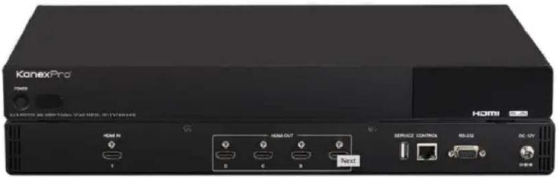
The KanexPro VW-SP-1X44K is a 4K based video processor which allows one HDMI input to be freely arranged on to four 4K displays. It offers bezel correction support with a simple and easy to use control application. The device supports video output timings up to WUXGA@60 and 1080p@60Hz, audio format up to 7.1CH LPCM at 192kHz sampling rate based on input source EDID.
2. APPLICATIONS
• Public Advertisement
• Digital Presentation
• Hypermarket Display
- Stock Market
3. PACKAGE CONTENTS
- 1× VW-SP1X44K
• 1× 12 V/3 A DC Power Adaptor
• 1× Operation Manual
4. SYSTEM REQUIREMENTS
Input Source such as PC/ Media Player, DVD/Blu-ray players or any HDMI signal and output HD TV/displays.
5. FEATURES
■ 1x4 Video Processor with Built-in Bezel Correction and Control
■ Can be cascaded to create up to 3x3 Video Wall (9- displays)
■ Can also be used as a 1x4 DA (splitter)
■ Supports 4K x 2K@24/25/30Hz
■ HDCP compliant
■ Outputs video signal to 4 displays with a full image & adjustable Bezel Correction
■ Input PC resolutions: from VGA\~WUXGA & HDTV from 480i\~1080p & 4K2K@24/25/30Hz
■ Various Audio Format Support: AC3/DTS/Dolby Digital Plus/Dolby TrueHD/Dolby Atmos and DTS-HD Master Audio
■ Control via RS-232 & Telnet (Ethernet)
■ One locking power supply included
■ 1U (19") rack mountable enclosure
■ Backed by KanexPro 3-year parts and labor warranty
6. OPERATION CONTROLS AND FUNCTIONS
6.1 Front Panel
natural_image
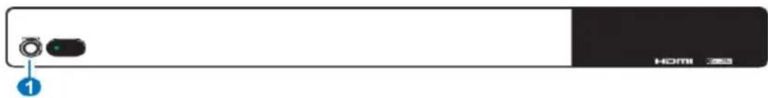
Front view of a black home screen with a circular button and indicator lights, labeled with '1' and 'HOMI 350' (no additional text or symbols)① POWER:
Press POWER button to power on the unit or set to standby mode.
When power is disconnected, presses this button and connected the power to reset the system back to default factory setting.
When power is on, long press this button for 3 seconds, output monitor will show "USB Host Update MCU Firmware Start...", then plug USB (with Firmware upgrade bin file contained) to upgrade automatically. If monitor shows "Mass Storage Host Upgrade Running" it means that the upgrade is proceeding, after upgrade finished, the unit will reboot.
Note: If monitor didn't show "Mass Storage Host Upgrade Running", means firmware upgrade didn't success, please power off the unit and try again.
6.2 Rear Panel
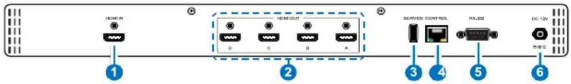
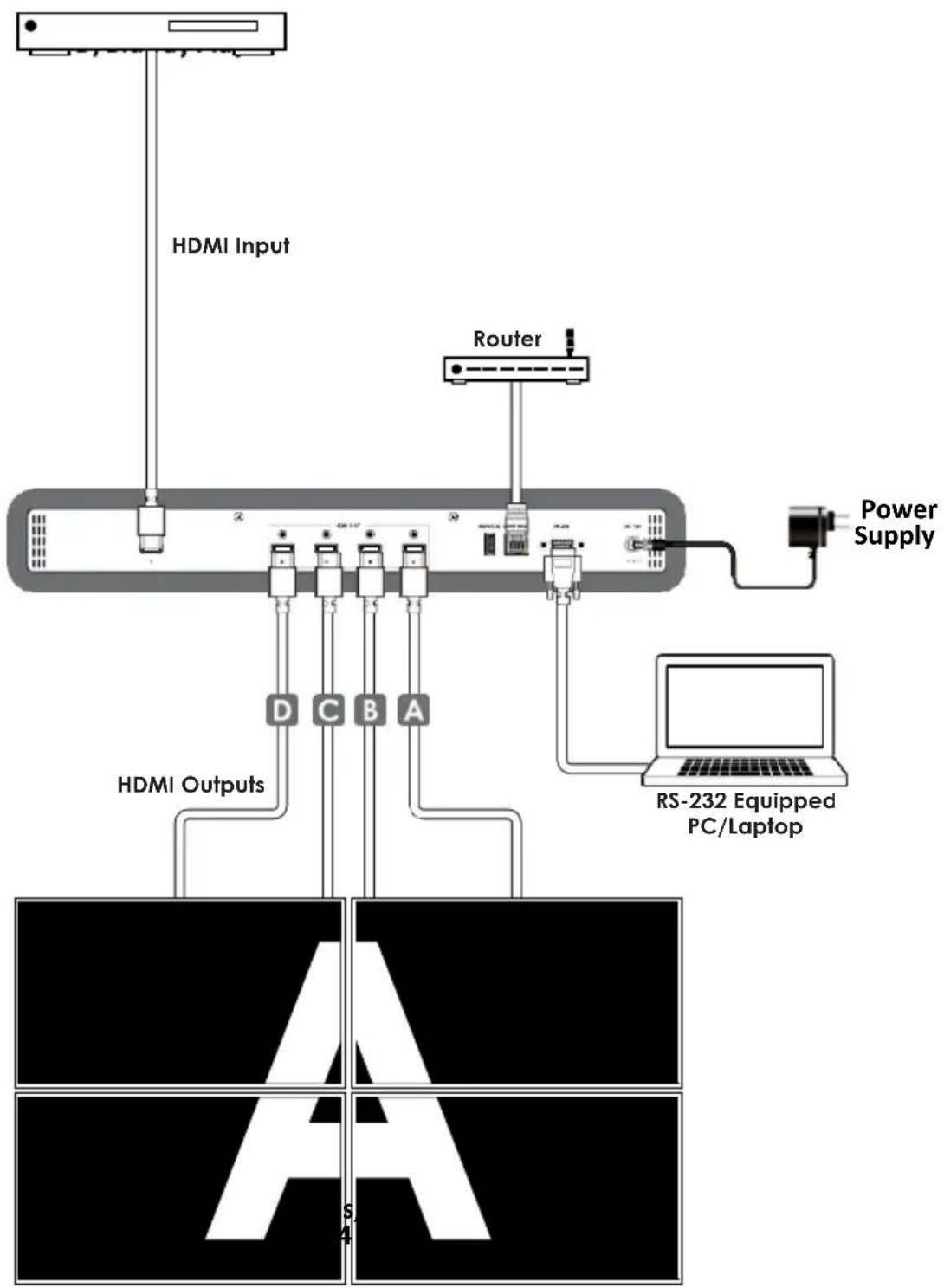
① HDMI IN: Connect with HDMI source equipment such as DVD/Blue-ray players and or PC/Laptop devices.
② HDMI OUT A\~D: Connect with HDMI TV/displays for output image display. It is suggested that the connection sequence should be placed as diagram showed below for TV wall set up.
③ SERVICE: This slot is for firmware update use only, work in accordingly with Power button.
④ CONTROL: Connect to an active network for telnet control. Collocated with "VW-SP1X44K AP" application could do multi-device control.
⑤ RS-232: Connect from PC/Laptop with D-Sub 9pin cables for RS-232 command sending and controlling over the device.
Note: RS-232 control system is limited to a single Video Wall unit. Whereas Telnet can control multi-Video Wall unit.
⑥ DC 12V: Plug 12V DC power supply which included in the package into the unit then connect the adaptor to an AC outlet.
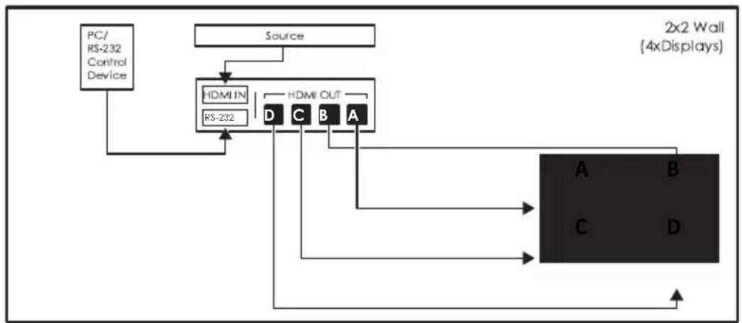
flowchart
graph TD
    A["PC/RS-232 Control Device"] --> B["Source"]
    B --> C["HDMI IN"]
    C --> D["D"]
    C --> E["C"]
    C --> F["B"]
    C --> G["A"]
    D --> H["A"]
    E --> I["B"]
    F --> J["C"]
    G --> K["D"]
    H --> L["2x2 Wall (4xDisplays)"]
    I --> L
    J --> L
    K --> L

flowchart
graph TD
    A["Source"] --> B["Splitter"]
    B --> C["PC"]
    C --> D["Router"]
    D --> E["HDMI IN"]
    E --> F["Control"]
    F --> G["HDMI OUT"]
    G --> H["A B C"]
    G --> I["D E F"]
    J["3x2 Wall (6xDisplays)"] --> K["3x3 Wall (9xDisplays)"]
    L["Source"] --> M["Splitter"]
    M --> N["PC"]
    N --> O["Router"]
    O --> P["HDMI IN"]
    P --> Q["Control"]
    Q --> R["HDMI OUT"]
    R --> S["A B C"]
    R --> T["D E F"]
    R --> U["G H I"]
    M --> V["HDMI IN"]
    V --> W["Control"]
    W --> X["HDMI OUT"]
    X --> Y["L K J I"]
6.3 RS-232 Protocols
| HDMI SPLITTER | |
| Pin | Definition |
| 1 | NC |
| 2 | TxD |
| 3 | RxD |
| 4 | NC |
| 5 | GND |
| 6 | NC |
| 7 | NC |
| 8 | NC |
| 9 | NC |
▲
| REMOTE CONTROL (PC) | |
| Pin | Definition |
| 1 | NC |
| 2 | RxD |
| 3 | TxD |
| 4 | NC |
| 5 | GND |
| 6 | NC |
| 7 | NC |
| 8 | NC |
| 9 | NC |
Baud Rate: 115200bps
Data Bit: 8 bits
Parity: None
Flow Control: None
Stop Bit: 1
6.4 RS-232 and Telnet Commands
| COMMAND DESCRIPTION PARAMETER | ||
| HELP(?) | Show Command list | NONE |
| HELP(?) N | Show Command description | N=Command name |
| RRES | Request Current Output Resolution | NONE |
| SRES N1 | Set Output Resolution to N1 | N1=0(640x480@60), 1(480p60), 2(576p50), 3(800x600@60), 4(848x480@60), 5(1024x768@60), 6(720p50), 7(720p60), 8(1280x768@60), 9(1280x800@60), 10(1280x960@60), 11(1280x1024@60), 12(1360x768@60), 13(1366x768@60), 14(1400x1050@60), 15(1440x900@60), 16(1600x900RB@60), 17(1600x1200@60), 18(1680x1050@60), 19(1080p50), 20(1080p60), 21(1920x1200RB@60), 22(2048x1152RB@60), 23(1080l50), 24(1080l60), 25(1080p24), 26(1080p25), 27(1080p30), 28(Native) |
| COMMAND | DESCRIPTION | PARAMETER |
| RINS | Get Input Resolution | 0(VGA60), 1(VGA72),2(VGA75), 3(VGA85),4(WXGA60), 5(WXGA75),6(XGA60), 7(XGA70),8(XGA75), 9(XGA85),10(SXGA60), 11(SXGA75),12(SVGA56), 13(SVGA60),14(SVGA72), 15(SVGA75),16(SVGA85),17(DTV_480P60),18(DTV_576P50),19(DTV_480I60),20(DTV_576I50),21(HDTV_720P50),22(HDTV_720P60),23(HDTV_1080I50),24(HDTV_1080I60),25(HDTV_1080P24),26(HDTV_1080P50),27(HDTV_1080P60),28(V848_480_60),29(V852_480_60),30(V854_480_60),31(V1024_852_60),32(V1024_1024_60),33(V1280_800_60),34(V1280_960_60),35(V1360_768_60),36(V1366_768_60),37(V1440_900_60),38(V1400_1050_60),39(V1360_1024_60),40(V1600_900_60),41(V1600_1200_60),42(V1680_1050_60),43(V1920_1200_60),44(V2048_1080_24_1),45(V2048_1080_24_2), |
| COMMAND DESCRIPTION PARAMETER | ||
| 46(V2048_1080_60), 47(V2048_1152_1), 48(V2048_1152_2), 49(V2048_1152_3), 50(V3840_2160_24), 51(V3840_2160_25), 52(V3840_2160_30), 53(V4096_2160_24), 54(K_NO_SIGNAL), | ||
| ROSDD | Request Current OSD Display State | NONE |
| SOSDD N1 | Set OSD Display Enable/Disable | N1=0(OFF), 1(ON) |
| ROSDH | Request Current OSD Horizontal Position | NONE |
| SOSDH N1 | Set OSD Horizontal Position to N1 | N1=0~20 (5) |
| ROSDV | Request Current OSD Vertical Position | NONE |
| SOSDV N1 | Set OSD Vertical Position to N1 | N1=0~20 (5) |
| ROSDT | Request OSD Display Current Timeout Setting | NONE |
| SOSDT N1 | Set OSD Display Timeout Setting | N1=0(Off), 5~50 (50) |
| ROSDG | Request OSD Gain Correction | NONE |
| SOSDG N1 | Set OSD Gain Value | N1=0~10 (2) |
| SOSDI | Show OSD Information On/Off | NONE |
| SOSDR | Reset All OSD Settings | NONE |
| RBRI N1 | Request Channel N1 Brightness Value | N1= 1~4 |
| SBRI N1 N2 | Set Channel N1 Brightness Value to N2 | N1= 1~4, N2=0~100(50) |
| RCON N1 | Request Chanel N1 Contrast Value | N1=1~4 |
| SCON N1 N2 | Set Channel N1 Contrast Value to N2 | N1= 1~4, N2=0~100(50) |
| RSAT | Request Current Saturation Value | NONE |
| RSAT N1 | Request Channel N1 Current Saturation Value | N1=1~4 |
| SSAT N1 N2 | Set Channel N1 Saturation Value to N2 | N1= 1~4, N2=0~100(50) |
| RHUE N1 | Request Channel N1 Current Hue Value | N1=1~4 |
| SHUE N1 N2 | Set Channel N1 Hue Value to N2 | N1= 1~4, N2=0~100 (50) |
| SIMRE N1 | Reset Brightness/Contrast/Saturation/Hue Value to Default | N1=1(Brightness), 2(Contrast), 3(Saturation), 4(Hue) |
| SPIRE | Reset all Channels Brightness, Contrast, Saturation, Hue Value to Default | NONE |
| RIPM | Request Current IP Mode | NONE |
| SIPM N1 | Set IP Mode to DHCP or Static | N1=0(Static), 1(DHCP) (192.168.1.50) |
| RIPA | Request Current Static IP Address to Screen | NONE |
| SIPA X.X.X.X | Set Static IP Address | X=0~255 (192.168.1.50) |
| RMAA | Request Current Static Subnet Address | NONE |
| SMAA X.X.X.X | Set Static Subnet Address | X=0~255 (255.255.255.0) |
| RGAA | Request Current Static Gateway Address | NONE |
| SGAA X.X.X.X | Set Static Gateway Address | X=0~255 (192.168.1.50) |
| RETIME | Request Current Ethernet Timeout | NONE |
| SETIME N1 | Set Ethernet Timeout | N1=0(OFF), 1(10 Minute), 2(20 Minute), 3(30 Minute), 4(40 Minute), 5(50 Minute), 6(60 Minutes) |
| RLINK | Request Ethernet Address | NONE |
| RMUTE | Request Current Mute | NONE |
| SMUTE N1 | Set Mute Audio | N1=0(Unmute), 1(Mute) |
| RPOW | Request Current Power State | NONE |
| SPOW N1 | Set the Unit Power On/Off | N1=0(Off), 1(On) |
| RVER | Request Version | NONE |
| SREL | Relink the Unit in 2 Seconds | NONE |
| SDEF | Reset the Unit to Factory Defaults | NONE |
| RMN | Request Current TV Wall Format | NONE |
| SMN N1 N2 | Set TV Wall N1 Row and N2 Column | N1=1~15(Row), N2=1~15(Column) |
| RBH | Request TV Wall Horizontal Bezel Correction | NONE |
| SBH N1 | Set TV Wall Horizontal Bezel Correction | N1=0~255 |
| RBV | Request TV Wall Vertical Bezel Correction | NONE |
| SBV N1 | Set TV Wall Vertical Bezel Correction | N1=0~255 |
| RBEZ | Request Current Bezel Correction State | NONE |
| SBEZ N1 | Set Bezel Correction Enable/Disable | N1=0(Off), 1(On) |
| RMDN | Request Unit ID Number | NONE |
| SMDN N1 | Set Unit ID Number to N1 | N1=0~255 |
| SWDE | Reset All TV Wall Settings | NONE |
| SHOT N1 | Fast Setting TV Wall Format from Hotkey N1 | N1=0(1x1), 1(2x2), 2(3x3), 3(4x4), 4(5x5), 5(6x6), 6(2x3), 7(3x2), 8(3x4), 9(4x2), 10(4x3), 11(4x5), 12(1x2), 13(2x1), 14(1x3), 15(3x1), 16(1x4), 17(4x1), 18(2x4), 19(3x5), 20(5x4), 21(5x2), 22(6x2), 23(6x2) |
| SFAVE N1 | Save Current TV Wall Settings to N1 | N1=1~5 |
| RFAVE N1 | Recall TV Wall Settings from N1 | N1=1~5 |
Note:
- All the RS-232 command will be not executed unless followed with a carriage return. All commands are insensitive.
- RS-232 control is set to single device only, not for use with Cascade/Bypass output's connection device.
- Bold values are the default settings.
6.5 Telnet Control
To access the Telnet control in Windows 7, click on the 'Start' menu and type "cmd" in the Search field then press Enter. Under Windows XP go to the 'Start' menu and click on "Run", type "cmd" with then press Enter.
Under Mac OS X, go to Go→Applications→Utilities→Terminal. See below for reference.


Once in the command line interface (CLI) type 'telnet', then the IP address of the unit (default is 192.168.1.50) and hit Enter. If the Telnet port (unit's port) is not set to the default of "23" then the correct port number will need to be entered after the IP address as shown below.
Microsoft Windows [Version 6.1.7601]
Copyright (c) 2009 Microsoft Corporation. All rights reserved.
C:\Users\Administrator>telnet 192.168.5.80 23
This will bring us into the unit which we wish to control. Type 'HELP' to list the available commands.
| Command List |
| HELP |
| RRES |
| SRES |
| ROSDD |
| SOSDD |
| ROSDH |
| SOSDH |
| ROSDU |
| SOSDU |
| ROSDT |
| SOSDT |
| ROSDG |
| SOSDC |
| SOSDI |
| SOSDR |
| RBRI |
| SBRI |
| RCON |
| SCON |
| RSAT |
| SSAT |
| RHUE |
| SHUE |
| SIMRE |
| SPIRE |
| RIPM |
| SIPM |
| RIPA |
| SIPA |
| RMAA |
| SMRA |
| RGAA |
| SCAA |
| RETIME |
| SETIME |
| RLINK |
| SREL |
| RMUTE |
| SMUTE |
| RPOW |
| SPOW |
| SDEF |
| RVER |
| RMN |
| SMN |
| RBH |
| CBH |
| RBU |
| SBU |
| RBEZ |
| SBEZ |
| RMDN |
| SMDN |
| SHOT |
| SPAUE |
| RFAUE |
| SWDE |
Note:
-
All the commands will be not executed unless followed by a carriage return. Commands are case-insensitive.
-
If the IP is changed then the IP Address required for Telnet access will also change accordingly.
6.6 PC Application Control
Use the link http://cypress.com.tw to download the software application of 1 By 4 HDMI 4K UHD Video Wall Splitter and execute it to control the Video Wall system.
Note: Before installing, remove any former version that was existing.
Once the application is installed successfully, click and open the "Video Wall Set".
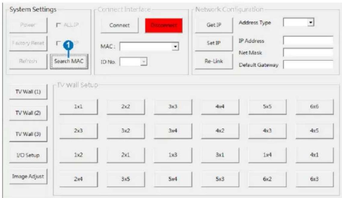
① Search MAC: Click on "Search MAC" to confirm how many TV unit(s) is within the network system then, select from here with the unit you wish to control.
Note: This action should be executed every time when the unit is power On or reset or re-run the "VW-SP1X44K AP" application.
Select the unit that is to be adjusted then pressed "Connect" to connecting the unit.
Every time when the unit is connected successfully, a dialog will appear showing “refresh completed” base on the selected MAC and the application will display current unit’s status. However, image display will not be refreshed automatically and can only be refreshed manually.
When using more than 1 unit for a TV Wall setting, set up unit's ID number is required to ensure the correct display of each single TV wall image.
6.6.1 System Settings

① Power: Click on "Power" to power on/off the controlled unit. To control all connected units, click on "ALL IP" then click Power. From power ON to power OFF the application will disconnect the link, to power ON again please re-Connect.
② Factory Reset: Click on "Factory Reset" to set device settings to default, to switch all devices back to default setting click ALL IP and then "Factory Reset".
③ Refresh: Click on "Refresh" to read device current settings, all status of TV Wall Set will follow current choose device.
Note: Image Adjust will not be refreshing, users have to click on "Image Adjust" to manually refresh to read Image Adjust current status.
④ Search MAC: Click on "Search MAC" to define on-line TV Wall units.
6.6.2 Connect Interface

① Connect: Click "Connect" to link the unit.
② Disconnect: Click "Disconnect" to terminate the link.
③ MAC: Click on "MAC" with the arrow down button to show all the TV Wall units and select the nominated unit/MAC for connection.
④ ID No.: When more than one TV Wall unit is in use, it is important that ID No. is set correctly in order to split and arrange the image correctly.
Note: All on-line units will show after running "Search MAC".
6.6.3 Network Configuration
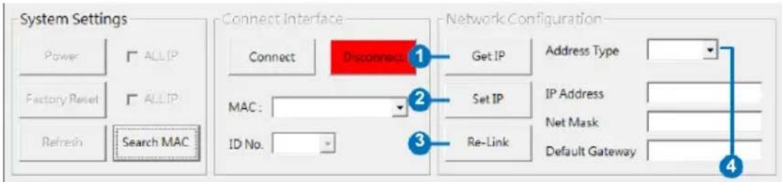
① Get IP: Click "Get IP" to show current linking status.
② Set IP: Click "Set IP" to adjust IP settings such as IP Type, IP Address...etc.
③ Re-Link: Click "Re-Link" to confirm Network Configuration settings changes.
④ Address Type: Click on this drop-down menu to change the address type to DHCP/Static mode.
6.6.4 TV Wall Setup (1)
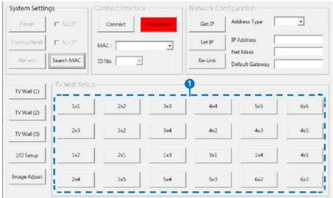
① Fast TV Wall Setting: TV Wall's fast setting. Click on hot key to pre-set the TV Wall setup.
6.6.5 TV Wall Setup (2)

① Manual Setup: Manually setup TV wall's setting by Rows and Columns from 1\~15 and click on Send to confirm the setting.
② Bezel Correction Horizon & Vertical: Set up Bezel Correction figures on the selected MAC/ID No. the correction will be made on all outputs of the selected unit in once.
③ Bezel Correction (ON/OFF): When the above action is taken Bezel, Correction will switch to ON automatically, to switch it off click on OFF to terminate the function. To execute Bezel Correction on all units, click on ALL IP. It is suggested that when displaying moving contents on the TV Wall the Bezel Correction should be set ON and when displaying static contents, the Bezel correction can be set OFF.
6.6.6 TV Wall Setup (3)
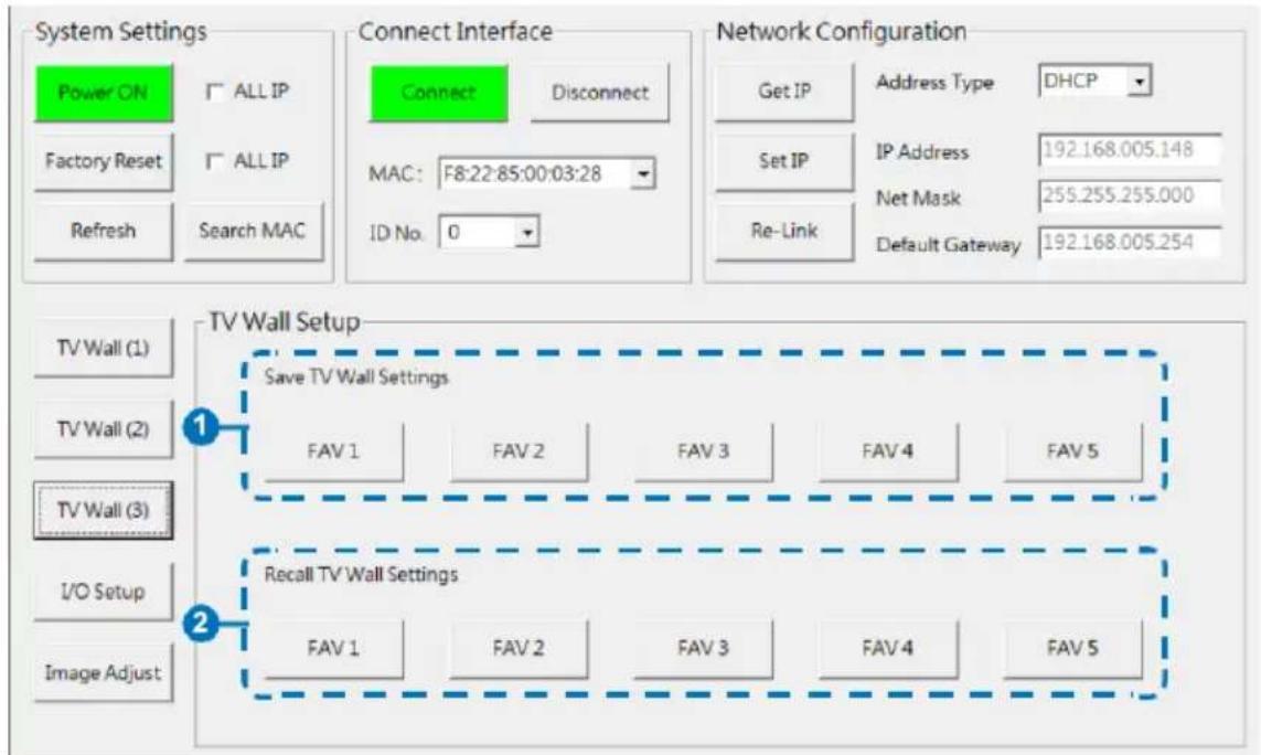
① Save TV Wall Settings: Save current setting to Favorite up to 5 settings allows.
② Recall TV Wall Settings: Recall restored TV Wall settings from 5 settings.
6.6.7 I/O Setup
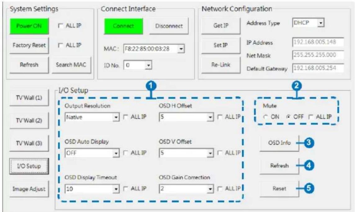
① Output Resolution and OSD Menu Adjustment: All settings under I/O Setup can be done with single TV Wall unit or units with a single click on "ALL IP". Parameter and default value are as stated in RS-232 description parameters.
② Mute: Set Audio Mute to ON/OFF.
③ OSD Info: Show/Close OSD Information.
④ Refresh: Refresh current page.
⑤ Reset: Reset current page.
6.6.8 Image Adjust

① Brightness, Contrast, Saturation and Hue Adjustment: Again, all settings under Image Adjust can be done with single TV Wall device or multiple TV Wall devices with single click on "ALL IP". Parameter and default value are as stated in RS-232 description.
② Picture Reset: Picture Reset button is to reset all settings of Image Adjust back to factory default value.
③ Refresh: Refresh button is to refresh Image Adjust page only.
Note:
- When Input signal is above 4K2K, device only support Color space RGB, YUV is not supported.
-
When on TV Wall split mode, different input/output resolution, signal is limited (please refer 9.3 Timing Limitation).
-
CONNECTION DIAGRAM
flowchart
graph TD
    A["Input"] --> B["HDMI Input"]
    B --> C["Router"]
    C --> D["Power Supply"]
    D --> E["RS-232 Equipped PC/Laptop"]
    E --> F["HDMI Outputs"]
    F --> G["Output 1"]
    F --> H["Output 2"]
    F --> I["Output 3"]
    F --> J["Output 4"]
    style A fill:#f9f,stroke:#333
    style B fill:#ccf,stroke:#333
    style C fill:#cfc,stroke:#333
    style D fill:#fcc,stroke:#333
    style E fill:#cff,stroke:#333
    style F fill:#ffc,stroke:#333
    style G fill:#fff,stroke:#333
    style H fill:#fff,stroke:#333
    style I fill:#fff,stroke:#333
    style J fill:#fff,stroke:#333
DVD/Blu-ray Player

flowchart
graph TD
    A["HDMI Input"] --> B["HDMI Splitter"]
    B --> C["HDMI Outputs"]
    C --> D["Router"]
    D --> E["RS-232 Equipped PC/Laptop"]
    C --> F["Power Supply"]
    F --> G["Cascade Output"]
    G --> H["HDMI Outputs"]
    H --> I["Power Supply"]
    I --> J["RS-232 Equipped PC/Laptop"]
    style A fill:#f9f,stroke:#333
    style B fill:#ccf,stroke:#333
    style C fill:#cfc,stroke:#333
    style D fill:#fcc,stroke:#333
    style E fill:#cff,stroke:#333
    style F fill:#ffc,stroke:#333
    style G fill:#cfc,stroke:#333
    style H fill:#cfc,stroke:#333
    style I fill:#fcc,stroke:#333
    style J fill:#ffc,stroke:#333
2×3 TVs/Displays (Total 6 Screens)
8. SPECIFICATIONS
8.1 Technical Specifications
Video Bandwidth 300 MHz/9 Gbps
Input Ports 1×HDMI (Female type), 1×Control (RJ45), 1×RS-232 (D-sub 9-pin), 1×USB (Service only)
Output Ports 4×HDMI (Female type) HDMI
Cable Distance 10M/8-bit 1080p, 5M/4K2K
Baud Rate 115200bps
ESD Protection Human body model: ± 8 kV (air-gap discharge) ± 4 kV (contact discharge)
Power Supply 12 V/3 A DC (US/EU standards, CE/FCC/UL certified) Dimensions 438mm (W)×269mm (D)44mm (H)/Jacks Excluded 482mm (W)×274mm (D)×52mm (H)/Jacks Included
Weight 2956 g
Chassis Material Metal
Color Black
Operating Temperature 0 C\~40 C / 32 F\~ 04 F Storage
Temperature -20 ℃\~60 ℃ / -4 ℃\~140 ℃
Relative Humidity 20\~90 % RH (non-condensing)
Power Consumption 12.98 W
8.2 Supported Resolutions
| INPUT RESOLUTION OUTPUT RESOLUTION | |
| 640×480@60/72/75/85 | 640×480 |
| 1280×768@60/75 | 480p@60 (720×480) |
| 1024×768@60/70/75/85 | 576p@50 (720×576) |
| 1280×1024@60/75 | 800×600 |
| 800×600@56/60/72/75/85 | 848×480 |
| 480p@60 | 1024×768 |
| 576p@50 | 720p@50 (1280×720) |
| 480i@60 | 720p@60 (1280×720) |
| 576i@50 | 1280×768 |
| 720p@50/60 | 1280×800 |
| 1080i@50/60 | 1280×960 |
| 1080p@24/50/60 | 1280×1024 |
| 848×480@60 | 1360×768 |
| 852×480@60 | 1366×768 |
| 854×480@60 | 1400×1050 |
| 1024×852@60 | 1440×900 |
| 1024×1024@60 | 1600×900 (RB) |
| 1280×800@60 | 1600×1200 |
| 1280×960@60 | 1680×1050 |
| 1360×768@60 | 1080p@50/60 |
| 1366×768@60 | 1920×1200 (RB) |
| 1440×900@60 | 2048×1152 (RB) |
| 1400×1050@60 | 1080i@50/60 |
| 1360×1024@60 | 1080p@24/25/30 |
| 1600×900@60 | |
| 1600×1200@60 | |
| 1680×1050@60 | |
| 1920×1200@60 | |
| 2048×1080@24 | |
| 2048×1152@60 | |
| 3840×2160@24/25/30 | |
| 4096×2160@24 | |
8.3 Output Resolution Limitations
8.3.1 Input Resolution is 3840×2160
| VIDEO WALL | 1X1 | 2X2 | 3X3 | 4X4 | 5X5 | 6X6 | 7X7 | 8X8 | 9X9 | 10X10 | 15X15 |
| 0. 640×480 | √ | √ | x | x | x | √ | √ | √ | √ | √ | √ |
| 1. 480p@60 (720×480) | √ | √ | x | x | x | √ | √ | √ | √ | √ | √ |
| 2. 576p@50 (720×576) | √ | √ | x | x | x | √ | √ | √ | √ | √ | √ |
| 3. 800×600 | √ | √ | x | x | √ | √ | √ | √ | √ | √ | √ |
| 4. 848×480 | √ | √ | x | x | √ | √ | √ | √ | √ | √ | √ |
| 5. 1024×768 | √ | √ | x | √ | √ | √ | √ | √ | √ | √ | √ |
| 6. 720p50 (1280×720) | √ | √ | √ | √ | √ | √ | √ | √ | √ | √ | √ |
| 7. 720p60 (1280×720) | √ | √ | √ | √ | √ | √ | √ | √ | √ | √ | √ |
| 8. 1280×768 | √ | √ | √ | √ | √ | √ | √ | √ | √ | √ | √ |
| 9. 1280×800 | √ | √ | √ | √ | √ | √ | √ | √ | √ | √ | √ |
| 10. 1280×960 | √ | √ | √ | √ | √ | √ | √ | √ | √ | √ | √ |
| 11. 1280×1024 | √ | √ | √ | √ | √ | √ | √ | √ | √ | √ | √ |
| 12. 1360×768 | √ | √ | √ | √ | √ | √ | √ | √ | √ | √ | √ |
| 13. 1366×768 | √ | √ | √ | √ | √ | √ | √ | √ | √ | √ | √ |
| 14. 1400×1050 | √ | √ | √ | √ | √ | √ | √ | √ | √ | √ | √ |
| 15. 1440×900 | √ | √ | √ | √ | √ | √ | √ | √ | √ | √ | √ |
| 16. 1600×900 (RB) | √ | √ | √ | √ | √ | √ | √ | √ | √ | √ | √ |
| 17. 1600×1200 | √ | √ | √ | √ | √ | √ | √ | √ | √ | √ | √ |
| 18. 1680×1050 | √ | √ | √ | √ | √ | √ | √ | √ | √ | √ | √ |
| 19. 1080p@50 | √ | √ | √ | √ | √ | √ | √ | √ | √ | √ | √ |
| 20. 1080p@60 | √ | √ | √ | √ | √ | √ | √ | √ | √ | √ | √ |
| 21. 1920×1200 (RB) | √ | √ | √ | √ | √ | √ | √ | √ | √ | √ | √ |
| 22. 2048×1152 (RB) | √ | √ | √ | √ | √ | √ | √ | √ | √ | √ | √ |
| 23. 1080i@50 | √ | √ | √ | √ | √ | √ | √ | √ | √ | √ | √ |
| 24. 1080i@60 | √ | √ | √ | √ | √ | √ | √ | √ | √ | √ | √ |
| 25. 1080p@24 | √ | √ | √ | √ | √ | √ | √ | √ | √ | √ | √ |
| 26. 1080p@25 | √ | √ | √ | √ | √ | √ | √ | √ | √ | √ | √ |
| 27. 1080p@30 | √ | √ | √ | √ | √ | √ | √ | √ | √ | √ | √ |
| 28. Native | √ | √ | √ | √ | √ | √ | √ | √ | √ | √ | √ |
8.3.2 Input Resolution is 4096×2160
| VIDEO WALL | 1X1 | 2X2 | 3X3 | 4X4 | 5X5 | 6X6 | 7X7 | 8X8 | 9X9 | 10X10 | 15X15 |
| 0. 640×480 | √ | √ | x | x | x | x | √ | √ | √ | √ | √ |
| 1. 480p@60 (720×480) | √ | √ | x | x | x | √ | √ | √ | √ | √ | √ |
| 2. 576p@50 (720×576) | √ | √ | x | x | x | √ | √ | √ | √ | √ | √ |
| 3. 800×600 | √ | √ | x | x | x | √ | √ | √ | √ | √ | √ |
| 4. 848×480 | √ | √ | x | x | √ | √ | √ | √ | √ | √ | √ |
| 5. 1024×768 | √ | √ | x | √ | √ | √ | √ | √ | √ | √ | √ |
| 6. 720p50 (1280×720) | √ | √ | x | √ | √ | √ | √ | √ | √ | √ | √ |
| 7. 720p60 (1280×720) | √ | √ | x | √ | √ | √ | √ | √ | √ | √ | √ |
| 8. 1280×768 | √ | √ | x | √ | √ | √ | √ | √ | √ | √ | √ |
| 9. 1280×800 | √ | √ | x | √ | √ | √ | √ | √ | √ | √ | √ |
| 10. 1280×960 | √ | √ | x | √ | √ | √ | √ | √ | √ | √ | √ |
| 11. 1280×1024 | √ | √ | x | √ | √ | √ | √ | √ | √ | √ | √ |
| 12. 1360×768 | √ | √ | √ | √ | √ | √ | √ | √ | √ | √ | √ |
| 13. 1366×768 | √ | √ | √ | √ | √ | √ | √ | √ | √ | √ | √ |
| 14. 1400×1050 | √ | √ | √ | √ | √ | √ | √ | √ | √ | √ | √ |
| 15. 1440×900 | √ | √ | √ | √ | √ | √ | √ | √ | √ | √ | √ |
| 16. 1600×900 (RB) | √ | √ | √ | √ | √ | √ | √ | √ | √ | √ | √ |
| 17. 1600×1200 | √ | √ | √ | √ | √ | √ | √ | √ | √ | √ | √ |
| 18. 1680×1050 | √ | √ | √ | √ | √ | √ | √ | √ | √ | √ | √ |
| 19. 1080p@50 | √ | √ | √ | √ | √ | √ | √ | √ | √ | √ | √ |
| 20. 1080p@60 | √ | √ | √ | √ | √ | √ | √ | √ | √ | √ | √ |
| 21. 1920×1200 (RB) | √ | √ | √ | √ | √ | √ | √ | √ | √ | √ | √ |
| 22. 2048×1152 (RB) | √ | √ | √ | √ | √ | √ | √ | √ | √ | √ | √ |
| 23. 1080i@50 | √ | √ | √ | √ | √ | √ | √ | √ | √ | √ | √ |
| 24. 1080i@60 | √ | √ | √ | √ | √ | √ | √ | √ | √ | √ | √ |
| 25. 1080p@24 | √ | √ | √ | √ | √ | √ | √ | √ | √ | √ | √ |
| 26. 1080p@25 | √ | √ | √ | √ | √ | √ | √ | √ | √ | √ | √ |
| 27. 1080p@30 | √ | √ | √ | √ | √ | √ | √ | √ | √ | √ | √ |
| 28. Native | √ | √ | √ | √ | √ | √ | √ | √ | √ | √ | √ |
8.3.3 Input Resolution is 2048×1080/2048×1152
| VIDEO WALL | 1X1 | 2X2 | 3X3 | 4X4 | 5X5 | 6X6 | 7X7 | 8X8 | 9X9 | 10X10 | 15X15 |
| 0. 640×480 | √ | √ | x | √ | √ | √ | √ | √ | √ | √ | √ |
| 1. 480p@60 (720×480) | √ | √ | √ | √ | √ | √ | √ | √ | √ | √ | √ |
| 2. 576p@50 (720×576) | √ | √ | √ | √ | √ | √ | √ | √ | √ | √ | √ |
| 3. 800×600 | √ | √ | √ | √ | √ | √ | √ | √ | √ | √ | √ |
| 4. 848×480 | √ | √ | √ | √ | √ | √ | √ | √ | √ | √ | √ |
| 5. 1024×768 | √ | √ | √ | √ | √ | √ | √ | √ | √ | √ | √ |
| 6. 720p50 (1280×720) | √ | √ | √ | √ | √ | √ | √ | √ | √ | √ | √ |
| 7. 720p60 (1280×720) | √ | √ | √ | √ | √ | √ | √ | √ | √ | √ | √ |
| 8. 1280×768 | √ | √ | √ | √ | √ | √ | √ | √ | √ | √ | √ |
| 9. 1280×800 | √ | √ | √ | √ | √ | √ | √ | √ | √ | √ | √ |
| 10. 1280×960 | √ | √ | √ | √ | √ | √ | √ | √ | √ | √ | √ |
| 11. 1280×1024 | √ | √ | √ | √ | √ | √ | √ | √ | √ | √ | √ |
| 12. 1360×768 | √ | √ | √ | √ | √ | √ | √ | √ | √ | √ | √ |
| 13. 1366×768 | √ | √ | √ | √ | √ | √ | √ | √ | √ | √ | √ |
| 14. 1400×1050 | √ | √ | √ | √ | √ | √ | √ | √ | √ | √ | √ |
| 15. 1440×900 | √ | √ | √ | √ | √ | √ | √ | √ | √ | √ | √ |
| 16. 1600×900 (RB) | √ | √ | √ | √ | √ | √ | √ | √ | √ | √ | √ |
| 17. 1600×1200 | √ | √ | √ | √ | √ | √ | √ | √ | √ | √ | √ |
| 18. 1680×1050 | √ | √ | √ | √ | √ | √ | √ | √ | √ | √ | √ |
| 19. 1080p@50 | √ | √ | √ | √ | √ | √ | √ | √ | √ | √ | √ |
| 20. 1080p@60 | √ | √ | √ | √ | √ | √ | √ | √ | √ | √ | √ |
| 21. 1920×1200 (RB) | √ | √ | √ | √ | √ | √ | √ | √ | √ | √ | √ |
| 22. 2048×1152 (RB) | √ | √ | √ | √ | √ | √ | √ | √ | √ | √ | √ |
| 23. 1080i@50 | √ | √ | √ | √ | √ | √ | √ | √ | √ | √ | √ |
| 24. 1080i@60 | √ | √ | √ | √ | √ | √ | √ | √ | √ | √ | √ |
| 25. 1080p@24 | √ | √ | √ | √ | √ | √ | √ | √ | √ | √ | √ |
| 26. 1080p@25 | √ | √ | √ | √ | √ | √ | √ | √ | √ | √ | √ |
| 27. 1080p@30 | √ | √ | √ | √ | √ | √ | √ | √ | √ | √ | √ |
| 28. Native | √ | √ | √ | √ | √ | √ | √ | √ | √ | √ | √ |
9. ACRONYMS
| ACRONYM COMPLETE TERM | |
| CLI | Command Line Interface |
| DTS | Digital Theater System |
| DVI | Digital Visual Interface |
| EDID | Extended Display Identification Data |
| GUI | Graphical User Interface |
| HDCP | High-bandwidth Digital Content Protection |
| HDMI | High-Definition Multimedia Interface |
| HDTV | High-Definition Television |
| OSD | On-Screen Display |
| USB | Universal Serial Bus |
| VGA | Video Graphics Array |
| WUXGA | Widescreen Ultra Extended Graphics Array |
- 1×4 HDMI 4K UHD Video Wall Processor with Bezel Correction
- SAFETY PRECAUTIONS
- CONTENTS
- INTRODUCTION
- APPLICATIONS
- PACKAGE CONTENTS
- SYSTEM REQUIREMENTS
- FEATURES
- OPERATION CONTROLS AND FUNCTIONS
- Front Panel
- ① POWER:
- Rear Panel
- RS-232 and Telnet Commands
- Note:
- Telnet Control
- PC Application Control
- System Settings
- Connect Interface
- Network Configuration
- TV Wall Setup (1)
- TV Wall Setup (2)
- TV Wall Setup (3)
- I/O Setup
- Image Adjust
- SPECIFICATIONS
- Technical Specifications
- Supported Resolutions
- Output Resolution Limitations
- Input Resolution is 3840×2160
- ACRONYMS
Brand : KanexPro
Model : VW-SP1X44K
Category : Processor