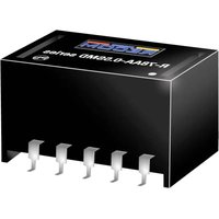
R-78AA12-0.5SMD - Audio/video converter Recom - Free user manual and instructions
Find the device manual for free R-78AA12-0.5SMD Recom in PDF.


| Product Type | Non-Isolated DC/DC Converter (Buck) |
| Model | R-78AA12-0.5SMD |
| Brand | Recom |
| Output Voltage (Nominal) | 12 VDC |
| Output Voltage Adjust Range | 4.5 to 12.6 VDC |
| Output Current | 0.5 A |
| Input Voltage Range | 15 to 32 VDC |
| Efficiency (min/max) | 94% / 97% |
| Switching Frequency | 330 kHz typical |
| Output Ripple and Noise | 30 mVp-p (9-15 Vout) / 40 mVp-p (1.5-6.5 Vout) |
| Line Regulation (9-15 Vout) | ±0.1% typical, ±0.2% max |
| Load Regulation (9-15 Vout) | ±0.25% typical, ±0.4% max |
| Transient Response (100%<->50% load) | ±85 mV typical, ±100 mV max |
| Protections | Continuous Short Circuit (automatic recovery), Thermal Shutdown |
| Remote On/Off Control | Yes (CTRL pin) |
| Operating Temperature Range | -40°C to +85°C (with derating) |
| Maximum Case Temperature | +100°C |
| Dimensions (L x W x H) | 15.3 x 9.6 x 8.8 mm |
| Weight | 2.7 g typical |
| Package Type | SMD (tube or tape & reel) |
| Certifications | EN60950-1, IEC60950-1, EAC, RoHS2+ |
| MTBF (+25°C) | 21,098 to 29,253 x 10³ hours |
Frequently Asked Questions - R-78AA12-0.5SMD Recom
User questions about R-78AA12-0.5SMD Recom
0 question about this device. Answer the ones you know or ask your own.
Ask a new question about this device
Download the instructions for your Audio/video converter in PDF format for free! Find your manual R-78AA12-0.5SMD - Recom and take your electronic device back in hand. On this page are published all the documents necessary for the use of your device. R-78AA12-0.5SMD by Recom.
USER MANUAL R-78AA12-0.5SMD Recom
• Efficiency up to 95%, no need for heatsinks
• High reflow temperature SMD package
- Adjustable output voltage buck converter
• Wide input range (4.74V - 32V)
- Short circuit protection, thermal shutdown
- Remote on/off control
• Very low shutdown current
• Positive to negative converter
Switching Regulator
Description
The R-78AAxx-0.5SMD series are adjustable output non-isolated buck converters that meet the requirements for RoHS 10/10 as well as the reflow soldering temperatures associated with vapor phase soldering, making these high efficiency switching regulators ideally suited to modern pick-and-place mass production. The efficiency of up to 97% means that very little energy is wasted as heat. The additional features of remote on/off control, continuous short circuit protection and adjustable output voltages will find many uses in the battery-powered, industrial, medical and automotive markets.
Selection Guide
Part Input Output Vout Output Efficiency
| Number | Voltage Range [VDC] (1) | Voltage [VDC] | Adjust Range [VDC] | Current [A] | @ min Vin [%] | @ max. Vin [%] |
| R-78AA1.5-0.5SMD | 4.75 - 30 | 1.5 | fixed | 0.5 | 73 | 63 |
| R-78AA1.8-0.5SMD | 4.75 - 32 | 1.8 | 1.5 - 3.0 | 0.5 | 82 | 71 |
| R-78AA2.5-0.5SMD | 4.75 - 32 | 2.5 | 1.5 - 3.0 | 0.5 | 87 | 77 |
| R-78AA3.3-0.5SMD | 4.75 - 32 | 3.3 | 3.0 - 5.5 | 0.5 | 91 | 81 |
| R-78AA5.0-0.5SMD | 6.5 - 32 | 5.0 | 3.0 - 8.0 | 0.5 | 94 | 86 |
| R-78AA6.5-0.5SMD | 8.0 - 32 | 6.5 | 3.3 - 11.0 | 0.5 | 95 | 88 |
| R-78AA9.0-0.5SMD | 11 - 32 | 9.0 | 4.5 - 12.6 | 0.5 | 96 | 92 |
| R-78AA12-0.5SMD | 15 - 32 | 12 | 4.5 - 12.6 | 0.5 | 97 | 94 |
| R-78AA15-0.5SMD | 18 - 32 | 15 | fixed | 0.5 | 97 | 95 |
Notes:
Note1: Input voltage ranges valid for nominal output voltages Vin must be higher than Vout including adjust range and dropout voltage
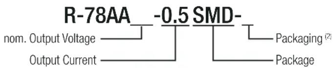
Model Numbering
Notes:
Note2: add suffix -R for tape & reel packaging
Ordering Examples:
R-78AA5.0-0.5SMD-R = 5.0VDC Output Voltage, 0.5A, SMD, tape and reel packaging R-78AA2.5-0.5SMD = 2.5VDC Output Voltage, 0.5A, SMD, tube
RECOM
DC/DC Converter
R-78AA-0.5
0.5 Amp
SMD

Single Output




EN60950-1 certified IEC60950-1 certified
Specifications (measured @ Ta= 25°C, 10% minimum load, unless otherwise stated)
BASIC CHARACTERISTICS
| Parameter Condition Min. Typ. Max. | |||||
| Absolute Maximum Input Voltage 34VDC | |||||
| Quiescent Current Vin= min. to max. | 5mA 7mA | ||||
| Internal Power Dissipation | 0.4W | ||||
| Output Voltage Adjustability | see calculation | ||||
| Minimum Load (3) | 0% | ||||
| Start-up time ON/OFF CTRL | 50ms | ||||
| ON/OFF CTRL | DC-DC ONDC-DC OFF | Open or 2.8VDC<Vr<5VDCGND or 0VDC<Vr<0.8VDC | |||
| Input Current of CTRL Pin DC-DC OFF | 1.8μA | ||||
| Standby Current | 20μA 30μA | ||||
| CTRL Thereshold Voltage | 2.4VDC 2.6VDC 2.8VDC | ||||
| CTRL Voltage Hysteresse | 250mV | ||||
| Internal Operating Frequency | 280kHz 330kHz 380kHz | ||||
| Output Ripple and Noise 20MHz BW | 1.5VDC tp 6.5VDC9VDC to 15VDC | 20mVp-p30mVp-p | 30mVp-p40mVp-p | ||
| Maximum Capacitive Load | with normal start-up time, no external components | 470μF | |||
| with <1 second start-up time + diode protection circuit | 6800μF | ||||
Notes:
Note3: Operation under no load will not harm the converter, but specifications may not be met. A minimum load of 6mA is recommended
Output Voltage Adjustability
Adjustment Resistor Values
continued on next page
Specifications (measured @ Ta= 25°C, 10% minimum load, unless otherwise stated)
Efficiency vs. Vin (full load)
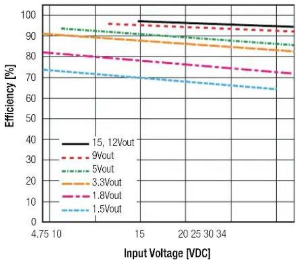
line
| Input Voltage [VDC] | 15, 12Vout | 9Vout | 5Vout | 3.3Vout | 1.8Vout | 1.5Vout | | ------------------- | ---------- | ----- | ----- | ------- | ------- | ------- | | 4.75 | 95 | 90 | 90 | 90 | 80 | 70 | | 10 | 95 | 90 | 90 | 90 | 80 | 70 | | 15 | 95 | 90 | 90 | 90 | 80 | 70 | | 20 | 95 | 90 | 90 | 90 | 80 | 70 | | 25 | 95 | 90 | 90 | 90 | 80 | 70 | | 30 | 95 | 90 | 90 | 90 | 80 | 70 | | 34 | 95 | 90 | 90 | 90 | 80 | 70 |Ripple vs. Vin (full load)

Efficiency vs. Load (max. Vin)

line
| Output Load [%] | 15Vout | 12Vout | 5Vout | 3.3Vout | 1.8Vout | 1.5Vout | | --------------- | ------ | ------ | ----- | ------- | ------- | ------- | | 0 | 80 | 75 | 70 | 65 | 45 | 40 | | 10 | 85 | 78 | 72 | 68 | 48 | 42 | | 20 | 90 | 80 | 75 | 70 | 50 | 45 | | 30 | 92 | 82 | 77 | 72 | 52 | 48 | | 40 | 94 | 84 | 79 | 74 | 54 | 50 | | 50 | 95 | 86 | 81 | 76 | 56 | 52 | | 60 | 96 | 88 | 83 | 78 | 58 | 54 | | 70 | 97 | 90 | 85 | 80 | 60 | 56 | | 80 | 97 | 91 | 86 | 81 | 62 | 58 | | 90 | 97 | 92 | 87 | 82 | 64 | 60 | | 100 | 97 | 93 | 88 | 83 | 65 | 62 | | >100 | ~97 | ~94 | ~89 | ~84 | ~66 | ~63 | The chart includes a legend for each output load level. The y-axis represents Efficiency [%]. The x-axis represents Output Load [%]. The legend indicates six different output load categories: '15Vout', '12Vout', '5Vout', '3.3Vout', '1.8Vout', and '1.5Vout'. The data is plotted as a line graph with distinct colors for each output level. The chart is saved as an image file named 'efficiency' and is displayed on the screen.Ripple vs. Load (max. Vin)
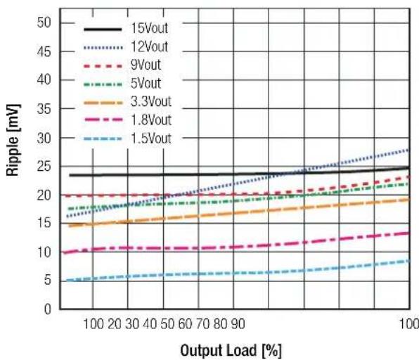
line
| Output Load [%] | 15Vout | 12Vout | 9Vout | 5Vout | 3.3Vout | 1.8Vout | 1.5Vout | | --------------- | ------ | ------ | ----- | ----- | ------- | ------- | ------- | | 100 | 24 | 26 | 20 | 18 | 15 | 10 | 5 | | 20 | 24 | 27 | 20 | 18 | 15 | 10 | 5 | | 30 | 24 | 28 | 20 | 18 | 15 | 10 | 5 | | 40 | 24 | 29 | 20 | 18 | 15 | 10 | 5 | | 50 | 24 | 30 | 20 | 18 | 15 | 10 | 5 | | 60 | 24 | 31 | 20 | 18 | 15 | 10 | 5 | | 70 | 24 | 32 | 20 | 18 | 15 | 10 | 5 | | 80 | 24 | 33 | 20 | 18 | 15 | 10 | 5 | | 90 | 24 | 34 | 20 | 18 | 15 | 10 | 5 | | 100 | 24 | 35 | 20 | 18 | 15 | 10 | 5 |Efficiency vs. Load (min. Vin)
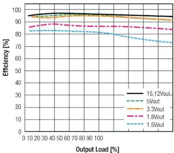
line
| Output Load [%] | 15,12Vout | 5Vout | 3.3Vout | 1.8Vout | 1.5Vout | | --------------- | --------- | ----- | ------- | ------- | ------- | | 0 | 95 | 94 | 93 | 86 | 82 | | 10 | 95 | 94 | 93 | 86 | 82 | | 20 | 95 | 94 | 93 | 86 | 82 | | 30 | 95 | 94 | 93 | 86 | 82 | | 40 | 95 | 94 | 93 | 86 | 82 | | 50 | 95 | 94 | 93 | 86 | 82 | | 60 | 95 | 94 | 93 | 86 | 82 | | 70 | 95 | 94 | 93 | 86 | 82 | | 80 | 95 | 94 | 93 | 86 | 82 | | 90 | 95 | 94 | 93 | 86 | 82 | | 100 | 95 | 94 | 93 | 86 | 82 | | >100 | ~94 | ~93 | ~92 | ~85 | ~75 | | >100 | ~94 | ~93 | ~92 | ~85 | ~75 | | >100 | ~94 | ~93 | ~92 | ~85 | ~75 | | >100 | ~94 | ~93 | ~92 | ~85 | ~75 | | >200 | ~94 | ~93 | ~92 | ~85 | ~75 | | >200 | ~94 | ~93 | ~92 | ~85 | ~75 | | >200 | ~94 | ~93 | ~92 | ~85 | ~75 | | >200 | | >200 | ~94 | ~93 | ~92 | ~85 | ~75 | | >200 | ~94 | ~93 | ~92 | ~85 | ~75 | | >200 | ~94 | ~93 | ~92 | ~85 | ~75 | | >300 | ~94 | ~93 | ~92 | ~85 | ~75 | | >300 | ~94 | ~93 | ~92 | ~85 | ~75 | | >300 | ~94 | ~93 | ~92 | ~85 | ~75 | | >300 | | >300 | ~94 | ~93 | ~92 | ~85 | ~75 | | >300 | ~94 | ~93 | ~92 | ~85 | ~75 | | >300 | ~94 | ~93 | ~92 | ~85 | ~75 | | >400 | ~94 | ~93 | ~92 | ~85 | ~75 | | >400 | ~94 | ~93 | ~92 | ~85 | ~75 | | >400 | ~94 | ~93 | ~92 | ~85 | ~75 | | >400 | | >400 | ~94 | ~93 | ~92 | ~85 | ~75 | | >400 | ~94 | ~93 | ~92 | ~85 | ~75 | | >400 | ~94 | ~93 | ~92 | ~85 | ~75 | | >500 | ~94 | ~93 | ~92 | ~85 | ~75 | | >500 | ~94 | ~93 | ~92 | ~85 | ~75 | | >500 | ~94 | ~93 | ~92 | ~85 | ~75 | | >500 | | >500 | ~94 | ~93 | ~92 | ~85 | ~75 | | >600 | ~94 | ~93 | ~92 | ~85 | ~75 | | >600 | ~94 | ~93 | ~92 | ~85 | ~75 | | >600 | ~94 | ~93 | ~92 | ~85 | ~75 | | >600 | | >600 | ~94 | ~93 | ~92 | ~85 | ~75 | | >700 | ~94 | ~93 | ~92 | ~85 | ~75 | | >700 | ~94 | ~93 | ~92 | ~85 | ~75 | | >700 | ~94 | ~93 | ~92 | ~85 | ~75 | | >700 | | >700 | ~94 | ~93 | ~92 | ~85 | ~75 | | >800 | ~94 | ~93 | ~92 | ~85 | ~75 | | >800 | ~94 | ~93 | ~92 | ~85 | ~75 | | >800 | ~94 | ~93 | ~92 | ~85 | ~75 | | >800 | | >800 | ~94 | ~93 | ~92 | ~85 | ~75 | | >100 | <1 each> <1, the output load is equal at the end of the range of the output load. However, the output load values are not explicitly provided in the code.Ripple vs. Load (min. Vin)
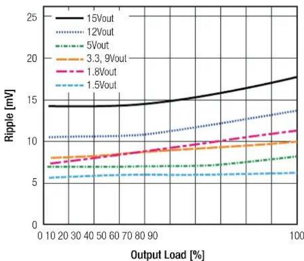
line
| Output Load [%] | 15Vout | 12Vout | 5Vout | 3.3, 9Vout | 1.8Vout | 1.5Vout | | --------------- | ------ | ------ | ----- | ---------- | ------- | ------- | | 0 | 14.0 | 10.5 | 7.0 | 7.5 | 7.0 | 5.5 | | 10 | 14.0 | 10.5 | 7.0 | 7.5 | 7.0 | 5.5 | | 20 | 14.0 | 10.5 | 7.0 | 7.5 | 7.0 | 5.5 | | 30 | 14.0 | 10.5 | 7.0 | 7.5 | 7.0 | 5.5 | | 40 | 14.0 | 10.5 | 7.0 | 7.5 | 7.0 | 5.5 | | 50 | 14.0 | 10.5 | 7.0 | 7.5 | 7.0 | 5.5 | | 60 | 14.0 | 10.5 | 7.0 | 7.5 | 7.0 | 5.5 | | 70 | 14.0 | 10.5 | 7.0 | 7.5 | 7.0 | 5.5 | | 80 | 14.0 | 10.5 | 7.0 | 7.5 | 7.0 | 5.5 | | 90 | 14.0 | 10.5 | 7.0 | 7.5 | 7.0 | 5.5 | | 100 | 18.0 | 14.0 | 8.0 | 10.0 | 11.0 | 6.0 |Specifications (measured @ Ta= 25°C, 10% minimum load, unless otherwise stated)
REGULATIONS
| Parameter | Condition | Value | |
| Output Accuracy | full load | ±2.0% typ. / ±3.0% max. | |
| Line Regulation | low line to high line at full load | 1.5 VDC tp 6.5VDC9VDC to 15VDC | ±0.2% typ. / ±0.4% max.±0.1% typ. / ±0.2% max. |
| Load Regulation | 10% to 100% load | 1.5 VDC tp 6.5VDC9VDC to 15VDC | ±0.7% typ. / ±1.0% max.±0.25% typ. / ±0.4% max. |
| Transient Response | with a 100μF output capacitor | 100% <-> 50% load100% <-> 10% load | ±85mV typ. / ±100mV max.±100mV typ. |
PROTECTIONS
| Parameter Condition Value | ||
| Short Circuit Protection (SCP) continuous, automatic recovery | ||
| Short Circuit Input Current nom. Vin= 24VDC 60mA typ. / 100mA max. | ||
Optional Diode Protection Circuit
Add a blocking diode to Vout if current can flow backwards into the output, as this can damage the converter when it is powered down.
The diode can either be fitted across the device if the source is low impedance or fitted in series with the output (recommended).
Optional Protection 1: Optional Protection 2:


ENVIRONMENTAL
| Parameter Condition | Value | ||
| Operating Temperature Range with derating (see graph) -40°C to +85°C | |||
| Maximum Case Temperature | +100°C | ||
| Temperature Coefficient | ±0.015%/°C | ||
| Thermal Impedance | 0.1m/s, horizontal | 70°C/W | |
| Operating Altitude | 2000m | ||
| Operating Humidity | non-condensing | 5% - 95% RH max. | |
| Pollution Degree | PD2 | ||
| MTBF | according to MIL-HDBK-217F, G.B. | +25°C | 21098 - 29253 x 103hours |
| +71°C | 4214 - 7365 x 103hours | ||
Derating Graph

line
| Ambient Temperature [°C] | Output Load [%] | | ------------------------ | --------------- | | 70 | 100 | | 85 | 60 |Specifications (measured @ Ta= 25°C, 10% minimum load, unless otherwise stated)
SAFETY AND CERTIFICATIONS
| Certificate Type (Safety) Report / File Number Standard | ||
| Information Technology Equipment, General Requirements for Safety | 1603123 | IEC60950-1:2005, 2nd Edition + AM 2:2013EN60950-1:2006 + AM 2:2013 |
| EAC RU-AT.49.09571 TP TC 004/2011 | ||
| RoHS 2+ RoHS 2011/65/EU + AM2015/863 | ||
| EMC Compliance Condition Standard / Criterion | ||
| Electromagnetic compatibility of multimedia equipment - Emission requirements | with external filter(see filter suggestion below) | EN55032, Class A and B |
| ESD Electrostatic discharge immunity test Air ±8kV; Contact ±4kV EN6 | 1000-4-2 | |
| Radiated, radio-frequency, electromagnetic field immunity test 3V/m EN | 61000-4-3 | |
EMC Filter Suggestion according to EN55032

Component List Class A
| MODEL | C1 | L1 |
| R-78AA5.0-0.5SMD | 10μF100V MLCC | 3.9μH chokeRLS-397 |
| R-78AA12-0.5SMD | ||
| R-78AA15-0.5SMD |
Component List Class B
| MODEL | C1 | C2 | L1 |
| R-78AA5.0-0.5SMD | 10μF100V MLCC | 10μF100V MLCC | 5.6μH chokeRLS-567 |
| R-78AA12-0.5SMD | |||
| R-78AA15-0.5SMD |
Notes:
Note4: Filter suggestions are valid for indicated part numbers only. For other part numbers, please contact RECOM tech support for advice
| DIMENSION AND PHYSICAL CHARACTERISTICS | ||
| Parameter Type | Value | |
| Material | casePCB | non-conductive black plastic, (UL94 V-2)FR4, (UL94 V-1) |
| Dimension (LxWxH) | 15.3 x 9.6 x 8.8mm | |
| Weight | 2.7g typ. | |
| continued on next page | ||
Specifications (measured @ Ta= 25°C, 10% minimum load, unless otherwise stated)
Dimension Drawing (mm)
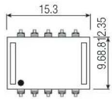


Recommended Footprint Details
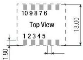

Pinning information
| Pin # Single |
| 1,2 +Vin |
| 3,7,8,9 GND |
| 4,5 +Vout |
| 6 Vadj |
| 10 CTRL |
Tolerance:
xx.x=0.5mm
xx.xx=±0.25mm
INSTALLATION AND APPLICATION
Standard Application Circuit

To protect the converter from high inrush currents, use soft start Vin and C1 = 10μF Output capacitor C2 recommended if load is very dynamic
Positive to Negative Converter
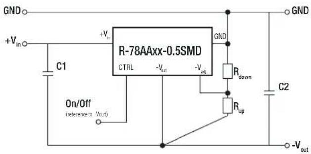
C1 and C2 are required and should be fitted close to the converter pins.
Maximum capacitiv load including C2 is 220μF
Pin Connections
| Pin # | Negative | Positive |
| 1,2 | +Vin | +Vin |
| 3,7,8,9 | -Vout | GND |
| 4,5 | GND | +Vout |
| 6 | -Vadj | +Vadj |
| 10 | CTRL | CTRL |

continued on next page
Specifications (measured @ Ta= 25°C, 10% minimum load, unless otherwise stated)
Selection Guide - Negative Output
| Part Number\Input | Output Voltage Range [VDC] | Output Voltage [VDC] | Efficiency Voltage [A] | External @ min Vin [%] | Capacitor @ max. Vin [%] | C1 | C2 (5) |
| R-78AA1.5-0.5SMD | 4.75 - 28 | -1.5 | -0.4 | 68 | 67 | 10μF/35V | 22μF/6.3V |
| R-78AA1.8-0.5SMD | 4.75 - 28 | -1.8 | -0.4 | 71 | 70 | 10μF/50V | 22μF/6.3V |
| R-78AA2.5-0.5SMD | 4.75 - 28 | -2.5 | -0.4 | 75 | 76 | 10μF/50V | 22μF/6.3V |
| R-78AA3.3-0.5SMD | 4.75 - 28 | -3.3 | -0.4 | 77 | 80 | 10μF/50V | 22μF/6.3V |
| R-78AA5.0-0.5SMD | 4.75 - 28 | -5.0 | -0.4 | 79 | 84 | 10μF/50V | 22μF/10V |
| R-78AA6.5-0.5SMD | 5.0 - 26 | -6.5 | -0.3 | 81 | 86 | 10μF/50V | 10μF/10V |
| R-78AA9.0-0.5SMD | 8.0 - 18 | -9.0 | -0.2 | 87 | 89 | 10μF/50V | 10μF/16V |
| R-78AA12-0.5SMD | 8.0 - 18 | -12 | -0.2 | 87 | 90 | 10μF/50V | 10μF/25V |
| R-78AA15-0.5SMD | 8.0 - 18 | -15 | -0.2 | 87 | 91 | 10μF/50V | 10μF/25V |
Notes:
Note5: Maximum Capacitive Load including C2 is 220μF
PACKAGING INFORMATION
| Parameter | Type | Value |
| Packaging Dimension (LxWxH) | tube | 530.0 x 17.0 x 13.0mm |
| tape and reel (carton) | 355.0 x 342.0 x 36.0mm | |
| Packaging Quantity | tube | 33pcs |
| tape and reel | 250pcs | |
| Tape Width | 24mm | |
| Storage Temperature Range | -55°C to +125°C | |
| Storage Humidity | 95% RH max. |
The product information and specifications may be subject to changes even without prior written notice. The product has been designed for various applications; its suitability lies in the responsibility of each customer. The products are not authorized for use in safety-critical applications without RECOM's explicit written consent. A safety-critical application is an application where a failure may reasonably be expected to endanger or cause loss of life, inflict bodily harm or damage property. The applicant shall indemnify and hold harmless RECOM, its affiliated companies and its representatives against any damage claims in connection with the unauthorized use of RECOM products in such safety-critical applications.

- Switching Regulator
- Description
- Notes:
- Model Numbering
- Ordering Examples:
- RECOM
- DC/DC Converter
- R-78AA-0.5
- Amp
- SMD
- Single Output
- Output Voltage Adjustability
- Optional Diode Protection Circuit
- Specifications (measured @ Ta= 25°C, 10% minimum load, unless otherwise stated)
- INSTALLATION AND APPLICATION
Brand : Recom
Model : R-78AA12-0.5SMD
Category : Audio/video converter