CXN1836-WN1 - Air conditioner Daizuki - Free user manual and instructions
Find the device manual for free CXN1836-WN1 Daizuki in PDF.


| Product Type | Split Air Conditioner |
| Model | CXN1836-WN1 |
| Brand | Daizuki |
| Cooling Capacity | 3.5 kW (12,000 BTU/h) |
| Heating Capacity | 3.8 kW (13,000 BTU/h) |
| Power Supply | 220-240 V ~ 50 Hz |
| Power Consumption (Cooling) | 1.1 kW |
| Energy Efficiency Ratio (EER) | 3.2 |
| Seasonal Energy Efficiency Ratio (SEER) | 4.0 |
| Refrigerant Type | R32 |
| Indoor Unit Dimensions (WxHxD) | 790 x 270 x 190 mm |
| Outdoor Unit Dimensions (WxHxD) | 700 x 550 x 280 mm |
| Indoor Unit Weight | 10 kg |
| Outdoor Unit Weight | 28 kg |
| Functions | Cooling, Heating, Dehumidification, Fan, Sleep Mode, Turbo |
| Control | Remote Control with LCD Display |
| Airflow Volume | 600 m³/h |
| Noise Level (Indoor) | 26-38 dB(A) |
| Noise Level (Outdoor) | 52 dB(A) |
| Maintenance | Clean air filters every month; professional cleaning recommended yearly |
| Safety Features | Overload protection, auto restart after power failure, anti-corrosion coating |
| Spare Parts Availability | Filters, remote control, drain pipe, installation bracket |
| Repairability | Modular design; components accessible for repair |
| Warranty | 2 years (parts and labor) |
Frequently Asked Questions - CXN1836-WN1 Daizuki
User questions about CXN1836-WN1 Daizuki
0 question about this device. Answer the ones you know or ask your own.
Ask a new question about this device
Download the instructions for your Air conditioner in PDF format for free! Find your manual CXN1836-WN1 - Daizuki and take your electronic device back in hand. On this page are published all the documents necessary for the use of your device. CXN1836-WN1 by Daizuki.
USER MANUAL CXN1836-WN1 Daizuki
Air conditioning & Heating
natural_image
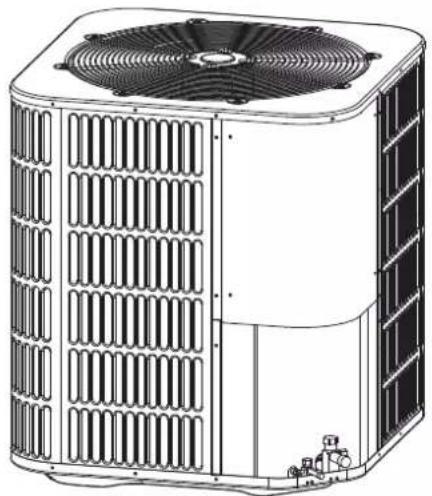
Technical line drawing of a dual-panel air conditioning unit with fan and ventilation grilles (no text or symbols)NOTE: Appearance of unit may vary.
Installer's Guide
Condensing Units
X DRIVE SERIES
Split System Heat Pump & Air Conditioner
Up to 18 SEER
2-5 Tons
R410A

ALL phases of this installation must comply with NATIONAL, STATE AND LOCAL CODES
IMPORTANT — This document is customer property and is to remain with this unit. Please return to service information pack upon completion of work.
These instructions do not cover all variations in systems or provide for every possible contingency to be met in connection with the installation. Should further information be desired or should particular problems arise which are not covered sufficiently for the purchaser's purposes, the matter should be referred to your installing dealer or local distributor.
Note : The manufacturer recommends installing only approved matched indoor and outdoor systems. All of the manufacturer's split systems are A.H.R.I. rated only with TXV indoor systems. And the indoor units must be matched with TXV Some of the benefits of installing approved matched indoor and outdoor split systems are maximum efficiency, optimum performance and the best overall system reliability.
Table of Contents
Section 1. Safety....2
Section 2. Unit Location Considerations....3
Section 3. Unit Preparation....5
Section 4. Setting the Unit....5
Section 5. Refrigerant Line Considerations....6
Section 6. Refrigerant Line Routing....7
Section 7. Refrigerant Line Brazing....8
Section 8. Refrigerant Line Leak Check....10
Section 9. Evacuation....11
Section 10. Service Valves....11
Section 11. Electrical - Low Voltage....12
Section 12. Electrical - High Voltage....14
Section 13. Start Up....15
Section 14. System Charge Adjustment....16
Section 15. System operation and Troubleshooting.....20
Section 1. Safety
Important - This document contains a wiring diagram and service information. This is customer property and is to remain with this unit. Please return to service information pack upon completion of work.

CAUTION
This information is intended for use by individuals possessing adequate backgrounds of electrical and mechanical experience. Any attempt to repair a central air conditioning product may result in personal injury and/or property damage. The manufacturer or seller cannot be responsible for the interpretation of this information, nor can it assume any liability in connection with its use.

WARNING
HAZARDOUS VOLTAGE!
Failure to follow this warning could result in property damage, severe personal injury, or death.
Disconnect all electric power, Including remote disconnects before servicing. Follow proper lockout/tagout procedures to ensure the power cannot be inadvertently energized.

WARNING
REFRIGERANT OIL!
Any attempt to repair a central air conditioning product may result in property damage, severe personal injury, or death.
These units use R-410A refrigerant which operates at 50 to 70% higher pressures than R-22. Use only R-410A approved service equipment. Refrigerant cylinders are painted a "Rose" color to indicate the type of refrigerant and may contain a "dip" tube to allow for charging of liquid refrigerant into the system. The R410 system of 2/3 tons with MITSUBISHI variable compressor uses PVE oil (FV50S or equal), and the R410 system of 4/5 tons with GMCC variable compressor uses POE oil (VG74 or equal). Both of them readily absorb moisture from the atmosphere. To limit this 'hygroscopic' action, the system should remain sealed whenever possible. If a system has been opened to the atmosphere for more than 4 hours, the compressor oil must be replaced. Never break a vacuum with air and always change the driers when opening the system for component replacement.

WARNING
HIGH CURRENT LEAKAGE!
Failure to follow this warning could result in property damage, severe personal injury, or death.
Earth connection essential before connecting electrical supply.

CAUTION
CONTAINS REFRIGERANT!
Failure to follow proper procedures can result in personal illness or injury or severe equipment damage. System contains oil and refrigerant under high pressure. Recover refrigerant to relieve pressure before opening system.

CAUTION
GROUNDING REQUIRED!
Failure to inspect or use proper service tools may result in equipment damage or personal injury.
Reconnect all grounding devices. All parts of this product that are capable of conducting electrical current are grounded. if grounding wires, screws, straps, clips, nuts, or washers used to complete a path to ground are removed for service, they must be returned to their original position and properly fastened.

CUTION
INDOOR UNIT REQUIRED!
The indoor unit must be matched with TXV. And the model of TXV can be charged according to the system capacity

WARNING
SERVICE VALVES!
Failure to follow this warning will result in abrupt release of system charge and may result in personal injury and/or property damage. Extreme caution should be exercised when opening the Liquid Line Service valve. Turn valve stem counterclockwise only until the stem contacts the rolled edge. No torque is required.

WARNING
BRAZING REQUIRED!
Failure to inspect lines or use proper service tools may result in equipment damage or personal injury. if using existing refrigerant lines make certain that all joints are brazed, not soldered.

CAUTION
HOT SURFACE!
May cause minor to severe burning. Failure to follow this caution could result in property damage or personal injury. Do not touch top of compressor.
Section 2. Unit Location Considerations
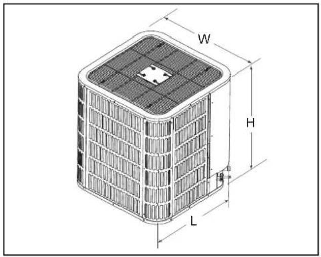
2.1 Unit Dimensions
| Unit Dimensions | |
| Models H x W x L(Inches) | |
| 24/36 | 24-15/16 x 29-1/8 x 29-1/8 |
| 48/60 | 33-3/16 x 29-1/8 x 29-1/8 |
The unit's weight values is on the carton box.
When mounting the outdoor unit on a roof, be sure the roof will support the unit's weight. Properly selected isolation is recommended to prevent sound or vibration transmission to the building structure.
2.2 Refrigerant Piping Limits
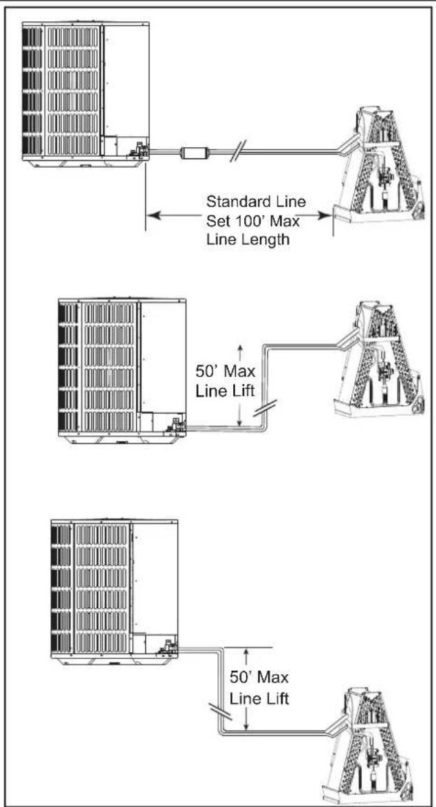
• Maximum line equivalent length = 100 feet.
• Maximum vertical equivalent length = 50 feet.
- Use only the line diameters indicated in Table 5.1.
- If the suction line sets are greater than 60 feet do not use a larger suction line than recommended.
2.4 Location Restrictions
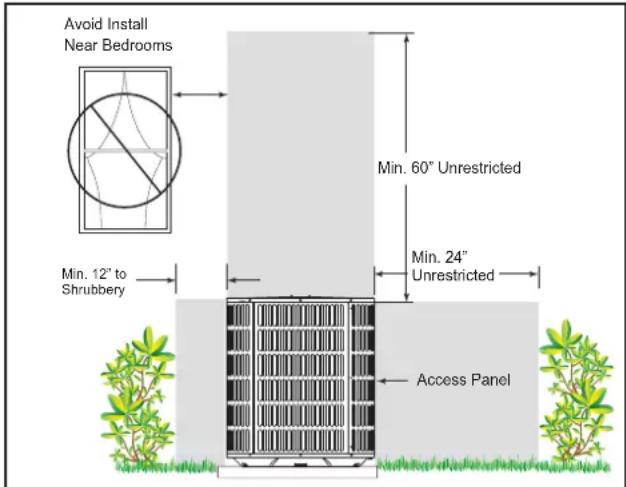
Ensure the top discharge area is unrestricted for at least 60 inches above the unit.
Clearance must be provided in front of the control box (access panels) and any other side requiring service.
Do not locate outdoor unit near bedrooms since normal operational sounds may be objectionable.
Position unit to allow adequate space for unobstructed airflow, wiring, refrigerant lines, and serciceability
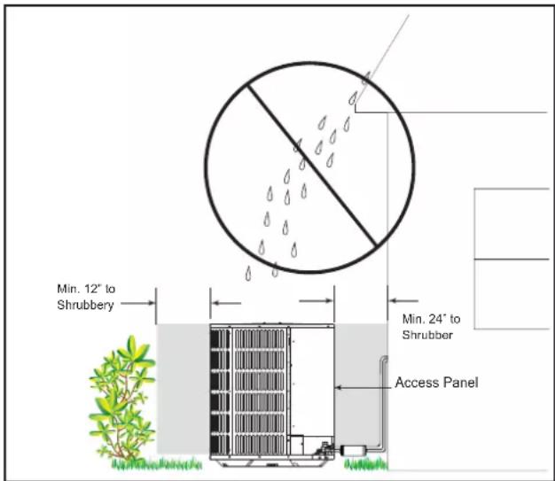
Allow a minimum of 12 in. clearance on one side of access panel to a wall and a minimum of 24 in. on the adjacent side of access panel.
Maintain a distance of 24 in. between units.
Position unit so water, snow, or ice from roof or overhang cannot fall directly on unit.
Only use this unit in well-ventilated spaces and ensure that there are no obstructions that could impede the airflow into and out of the unit.
Do not use this unit in the following locations:
- Locations with mineral oil.
- Locations with saline atmospheres, such as seaside locations.
- Locations with sulphurous atmospheres, such as near natural hot springs.
- Where high voltage electricity is present, such as in certain industrial locations.
- On vehicles or vessels, such as trucks or ferry boats.
- Where exposure to oily or very humid air may occur, such as kitchens.
- In proximity to sources of electromagnetic radiation, such as high-frequency transmitters or other high strength radiation devices.
Cold Climate Considerations (Heat Pump Only)
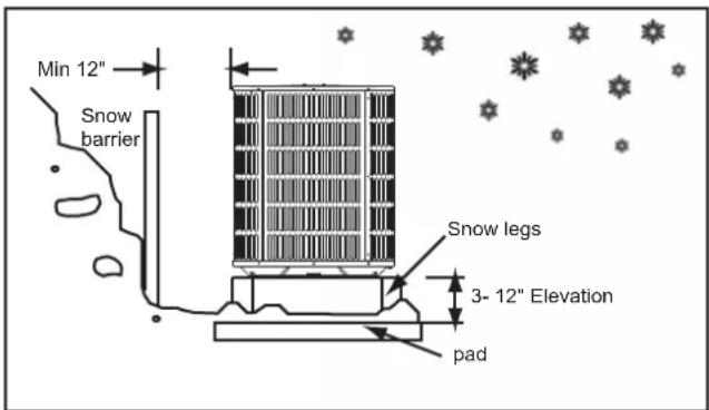
Note: It is recommended that these precautions be taken for units being installed in areas where snow accumulation and prolonged below-freezing temperatures occur.
- Units should be elevated 3-12 inches above the pad or rooftop, depending on local weather. This additional height will allow drainage of snow and ice melted during defrost cycle prior to its refreezing. Ensure that drain holes in unit base pan are not obstructed, preventing drainage of defrost water.
- If possible, avoid locations that are likely to accumulate snow drifts. if not possible, a snow drift barrier should be installed around the unit to prevent a build-up of snow on the sides of the unit.
Section 3. Unit Preparation
3.1 Prepare The Unit For Installation
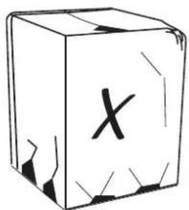
STEP 1 - Check for damage and report promptly to the carrier any damage found to the unit.
The charge port can be used to check to be sure the refrigerant charge has been retained during shipment.
Section 4. Setting the Unit

WARNING
LIVE ELECTRICAL COMPONENTS!
Check the electric wire, water and gas pipeline layout inside the wall, floor and ceiling before installation. Do not implement drilling unless confirm safety with the user, especially for the hidden power wire. An electroprobe can be used to test whether a wire is passing by at the drilling location, to prevent physical injury or death caused by insulation broken cords.
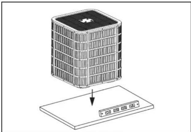
4.1 Pad Installation
When installing the unit on a support pad, such as a concrete slab, consider the following:
- The pad should be at least 1-2" larger than the unit on all sides.
- The pad must be separate from any structure.
• The pad must be level. - The pad should be high enough above grade to allow for drainage.
- The pad location must comply with National, State, and Local codes.
natural_image
Isometric illustration of a building with a star-shaped roof and a control panel below (no text or symbols)IMPORTANT NOTE:
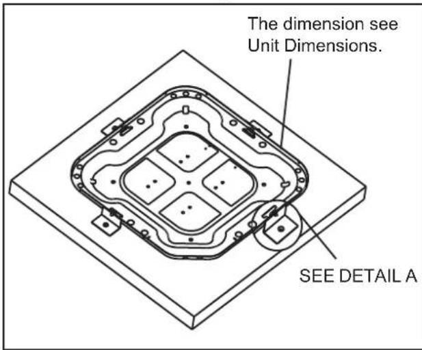
These instructions are intended to provide a method to tie-down system to cement slab as a securing procedure for high wind areas. It is recommended to check Local Codes for tie-down methods and protocols.
7 X 3/8" Self Tapping Screws (Don't Exceed 3/8" long)
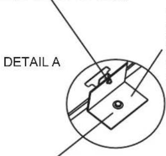
Brackets:
2" width, 1/16" thickness, height as required.
Available from distributor or in market place.
1/4" X 1-1/2" Hex Washer Head Concrete Screws (3/16" Pilot Hole Needed. Pilot Hole Should Be1/4" Deeper Than The Fastener Embedment)
Section 5. Refrigerant Line Considerations
5.1 Refrigerant Line and Service Valve Connection Sizes
Table 5.1
| Line Sizes Service Valve Connection Sizes | ||||
| Model | Suction Line | Liquid Line | Suction Line Connection | Liquid Line Connection |
| 24/36 | 3/4 3/8 | 3/4 3/8 | ||
| 48/60 | 7/8 7/8 | 3/8 3/8 | ||
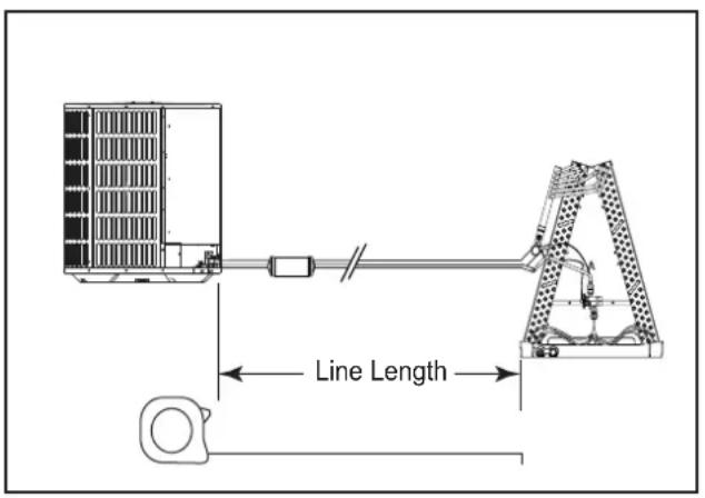
5.2 Required Refrigerant Line Length
Determine required line length.
5.3 Refrigerant Line Insulation
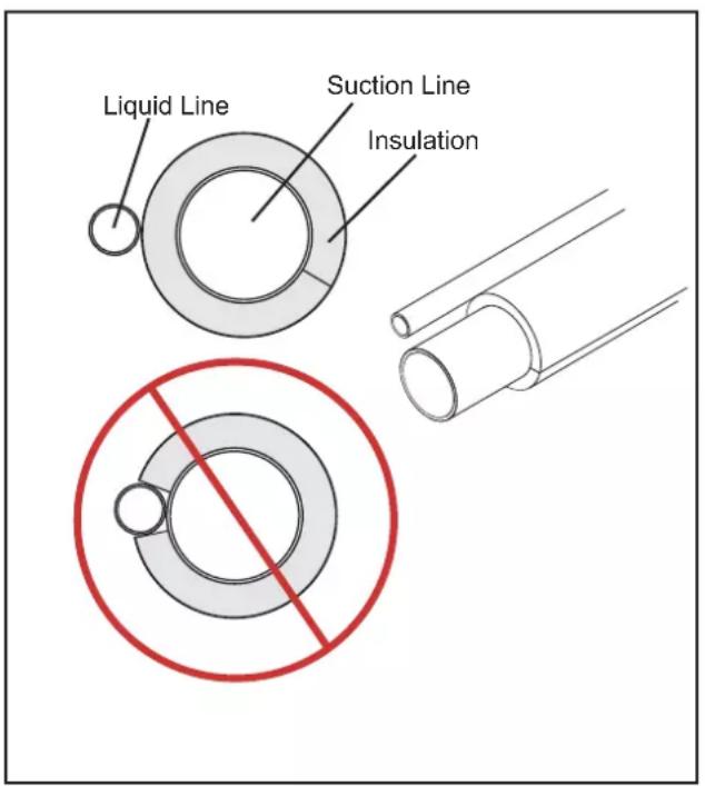
Important: The Suction Line must always be insulated. DO NOT allow the Liquid Line and Suction Line to come in direct (metal to metal) contact.
5.4 Reuse Existing Refrigerant Lines

CAUTION
If using existing refrigerant lines make certain that all joints are brazed, not soldered.
For retrofit applications, where the existing refrigerant lines will be used, the following precautions should be taken:
- Ensure that the refrigerant lines are the correct size. Refer to Section 2.2 listed and Table 5.1.
- Ensure that the refrigerant lines are free of leaks, acid, and oil.
Note: The manufacturer recommends installing only approved matched indoor and outdoor systems. All of the manufacturer's split systems are A.H.R.I. rated only with TXV indoor systems. Some of the benefits of installing approved matched indoor and outdoor split systems are maximum efficiency, optimum performance and the best overall system reliability.
natural_image
Technical line drawing of a wall-mounted bracket and base plate assembly (no text or symbols)Section 6. Refrigerant Line Routing
6.1 Precautions
Important: Take precautions to prevent noise within the building structure due to vibration transmission from the refrigerant lines.
Comply with National, State, and Local Codes when isolating line sets from joists, rafters, walls, or other structural elements.
For Example:
- When the refrigerant lines have to be fastened to floor joists or other framing in a structure, use isolation type hangers.
- Isolation hangers should also be used when refrigerant lines are run in stud spaces or enclosed ceilings.
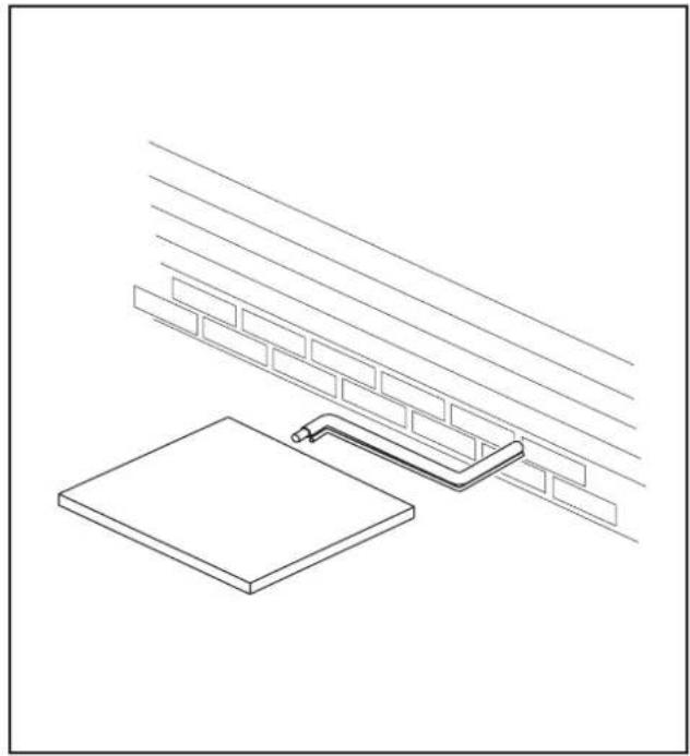
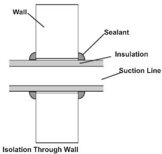
- Where the refrigerant lines run through a wall or sill, they should be insulated and isolated.
• Isolate the lines from all ductwork. - Minimize the number of 90^ turns.
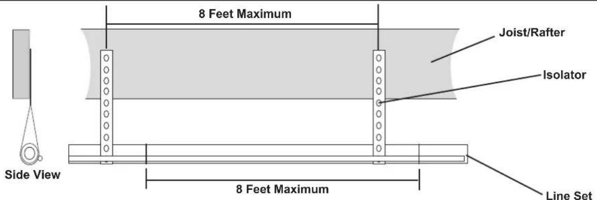
Secure Suction line from joists using isolators every 8 ft. Secure Liquid Line directly to Suction line using tape, wire, or other appropriate method every 8 ft.
Isolation From Joist/Rafter
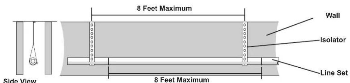
Secure Suction Line using isolators every 8 ft. Secure Liquid Line directly to Suction Line using tape, wire, or other appropriate method every 8 ft.
Isolation In Wall Spaces
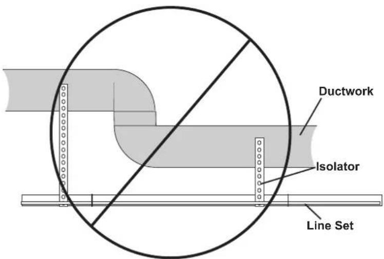
DO NOT hang line sets from ductwork
Section 7. Refrigerant Line Brazing
7.1 Braze The Refrigerant Lines
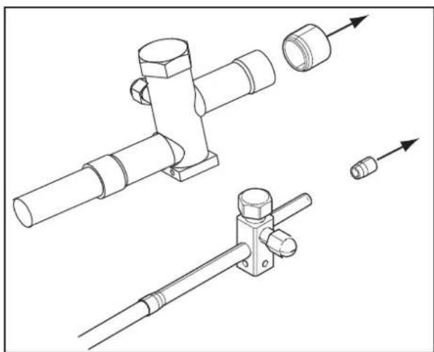
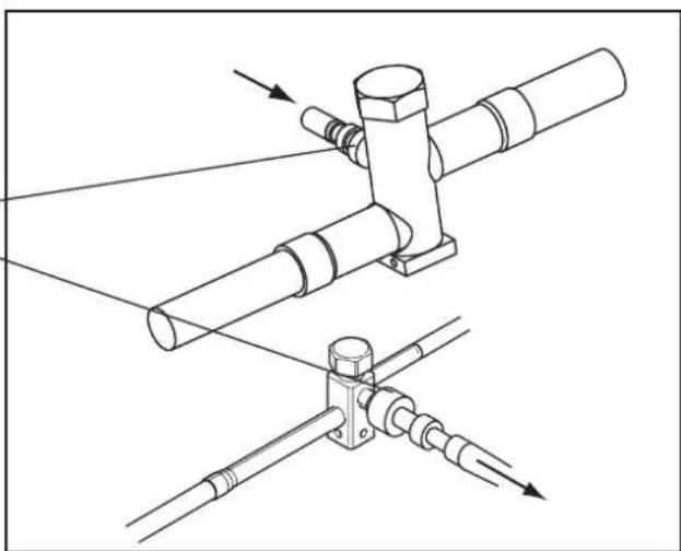
STEP 1 - Remove caps or plugs. Use a deburing tool to debur the pipe ends. Clean both internal and external surfaces of the tubing using an emery cloth.
natural_image
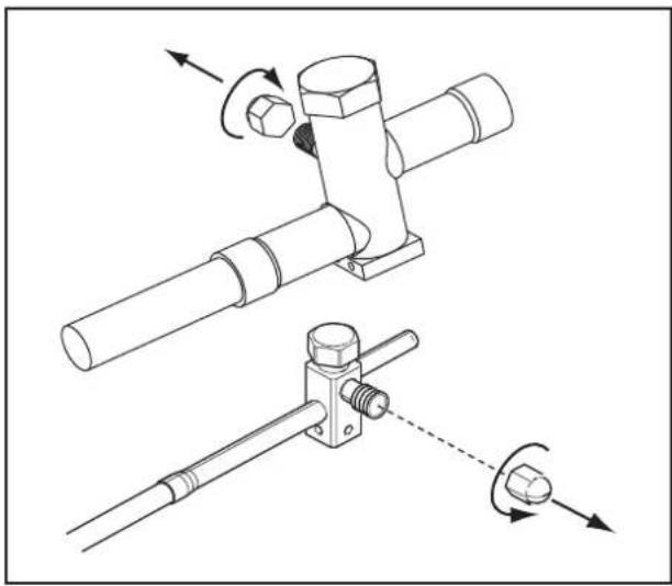
Technical line drawing of mechanical pipe fittings and connectors (no text or symbols)STEP 2 - Remove the pressure tap cap from both service valves.
natural_image
Technical line drawing of a mechanical assembly with two views: top shows a bolted joint, bottom shows a pin inserted into a bracket (no text or symbols)STEP 3 - Purge the refrigerant lines and indoor coil with dry nitrogen.
This pipe must have a thimble
natural_image
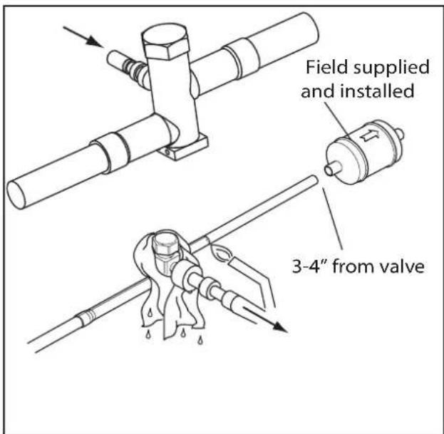
Technical line drawing of a mechanical assembly with two components and directional arrows indicating motion (no text or symbols)STEP 4 - Wrap a wet rag around the valve body to avoid heat damage and continue the dry nitrogen purge.
Braze the refrigerant lines to the service valves.
Check liquid line filter drier's directional flow arrow to confirm correct direction of refrigeration flow (away from outdoor unit and toward evaporator coil) as illustrated. Braze the filter drier to the Liquid Line.
Continue the dry nitrogen purge. Do not remove the wet rag until all brazing is completed.
Important: Remove the wet rag before stopping the dry nitrogen purge.
Note: Install drier in Liquid Line.
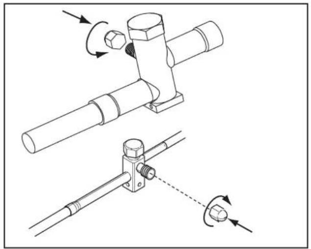
STEP 5 - Replace the pressure tap caps after the service valves have cooled.
natural_image
Technical line drawing of a mechanical assembly with two views showing rotational components (no text or symbols)Section 8. Refrigerant Line Leak Check
8.1 Check For Leaks
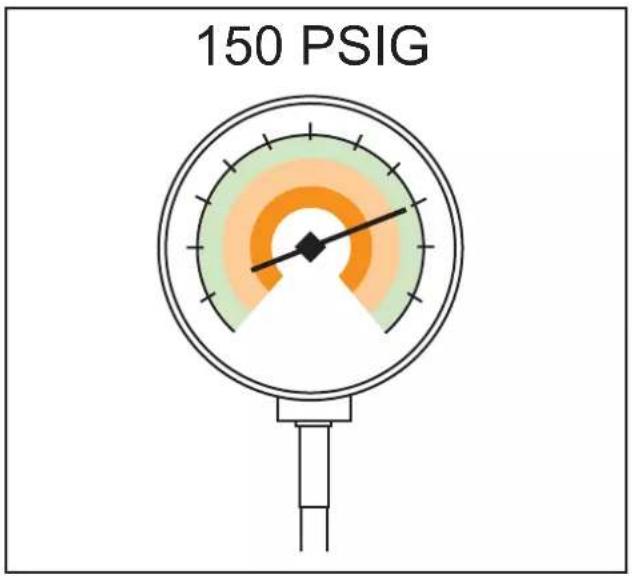
STEP 1 - Pressurize the refrigerant lines and evaporator coil to 150 PSIG using dry nitrogen.
gauge
150 PSIGSTEP 2 - Check for leaks by using a soapy solution or bubbles at each brazed location.
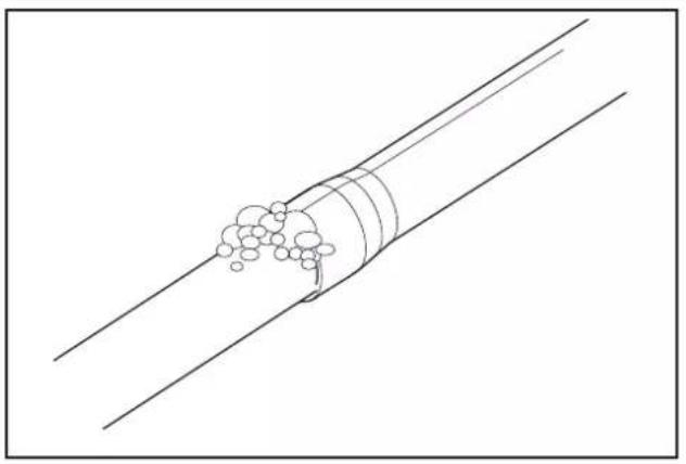
natural_image
Diagram of a pipe with particles flowing through it, intersected by two parallel lines (no text or symbols)Section 9. Evacuation
9.1 Evacuate the Refrigerant Lines and Indoor Coil
Important: Do not open the service valves until the refrigerant lines and indoor coil leak check and evacuation are complete.
STEP 1- Evacuate until the micron gauge reads no higher than 350 microns, then close the valve to the vacuum pump.
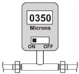
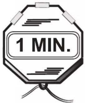
STEP 2- Observe the micron gauge. Evacuation is complete if the micron gauge does not rise above 500 microns in one (1) minute.
Once evacuation is complete blank off the vacuum pump and micron gauge, and close the valves on the manifold gauge set.
Section 10. Service Valves
10.1 Open the Service Valves
WARNING
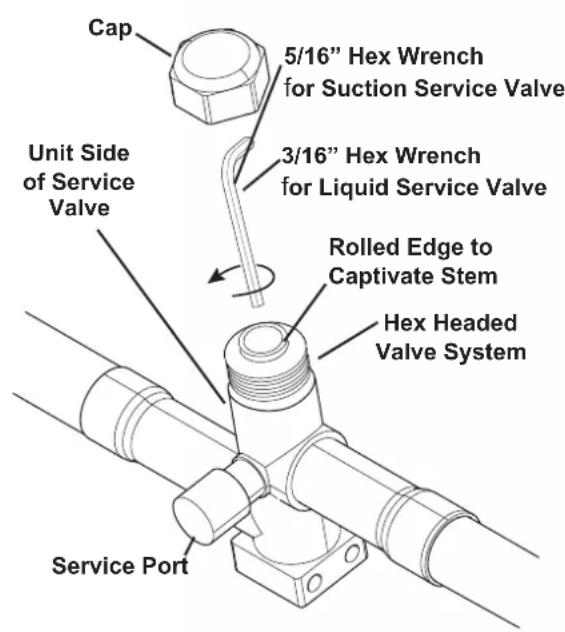
Extreme caution should be exercised when opening the Liquid Line Service Valve. Turn counterclockwise until the valve stem just touches the rolled edge. No torque is required. Failure to follow this warning will result in abrupt release of system charge and may result in personal injury and /or property damage.
Important: Leak check and evacuation must be completed before opening the service valves.
Important: The Suction Service Valve must be opened first BEFORE opening the Liquid Service Valve!
STEP 1 - Remove service valve cap.
STEP 2 - Fully insert hex wrench into the stem and back out counterclockwise until valve stem just touches the rolled edge (approximately five (5) turns.)
STEP 3 - Replace the valve stem cap to prevent leaks. Tighten finger tight plus an additional 1/6 turn.
STEP 4 - Repeat STEPS 1 - 3 for Liquid Service Valve.
Section 11. Electrical - Low Voltage
11.1 Low Voltage Maximum Wire Length
Table 11.1 defines the maximum total length of low voltage wiring from the outdoor unit, to the indoor unit, and to the thermostat.
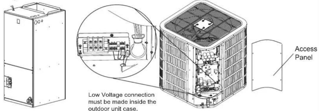
Field provided bushing or strain relief is required at the low voltage wire entry point.
Table 11.1
| 24 VOLTS | |
| WIRE SIZE MAX | WIRE LENGTH |
| 18 AWG 150 Ft | |
| 16 AWG 225 Ft | |
| 14 AWG 300 Ft | |
11.2 Low Voltage Hook-up Diagrams
Air Handler Hook-up Diagram
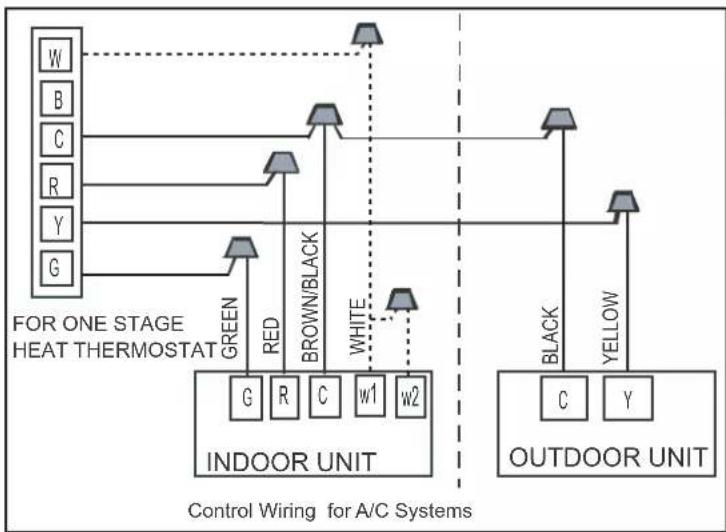
flowchart
graph TD
    subgraph_Control_Wing["FOR ONE STAGE HEAT THERMOSTAT"]
        W["W"] --> IND["INDOOR UNIT"]
        B["B"] --> IND
        C["C"] --> IND
        R["R"] --> IND
        Y["Y"] --> IND
        G["G"] --> IND
    end

    subgraph_Outdoor_Unit["OUTDOOR UNIT"]
        Black["BLACK"] --> IND
        Yellow["YELLOW"] --> IND
        G["G"] --> IND
        R["R"] --> IND
        C["C"] --> IND
        w1["w1"] --> IND
        w2["w2"] --> IND
    end

    IND -->|GREEN| W
    IND -->|RED| B
    IND -->|BROWN/BLACK| C
    IND -->|WHITE| W
    OUTDOuran["Control Wiring for A/C Systems"]
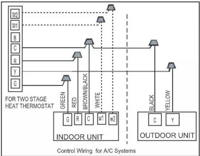
flowchart
graph TD
    subgraph Control Wiring for A/C Systems
        direction TB
        W2["Green"] --> G["G"]
        W1["Red"] --> R["R"]
        B["Brown/Black"] --> C["C"]
        C --> w1["w1"]
        C --> w2["w2"]
        y["Y"] --> G
        G --> W2
        W2 --> Y["Y"]
        W2 --> G
    end

    subgraph Outdoor Unit
        direction TB
        Black["Black"] --> C["C"]
        Black --> Y["Y"]
        Y["Y"] --> W2
        Black --> OUTDOORUNIT["OUTDOOR UNIT"]
        OUTDOORUNIT --> OUTDOORUNIT
    end

    W2 -->|FOR TWO STAGE HEAT THERMOSTAT| W2
    W1 -->|FOR TWO STAGE HEAT THERMOSTAT| W1
    B -->|FOR TWO STAGE HEAT THERMOSTAT| B
    C -->|FOR TWO STAGE HEAT THERMOSTAT| C
    R -->|FOR TWO STAGE HEAT THERMOSTAT| R
    Y -->|FOR TWO STAGE HEAT THERMOSTAT| Y
    G -->|FOR TWO STAGE HEAT THERMOSTAT| G
    OUTDOORUNIT --> OUTDOORUNIT
Notes:
- Be sure power supply agrees with equipment nameplate.
- Power wiring and grounding of equipment must comply with local codes.
- Low voltage wiring to be No. 18 AWG minimum conductor.
- "----"The electric auxiliary heat connection(option).
- W: Electric auxiliary heat signal.
- W1: The first Electric auxiliary heat signal.
- W2: The second Electric auxiliary heat signal.
Support 2H thermostat
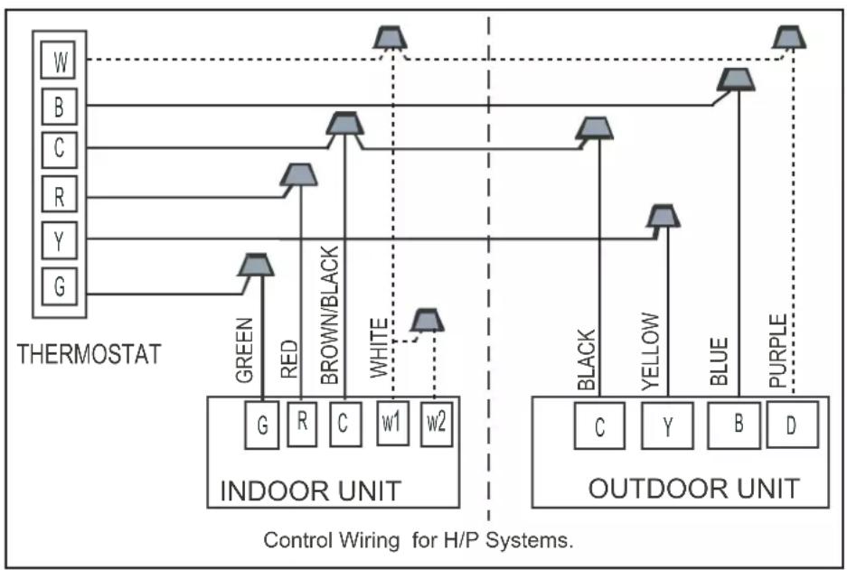
flowchart
graph TD
    subgraph Thermostat
        W["W"] -->|Green| G["G"]
        B["B"] -->|Red| R["R"]
        C["C"] -->|Brown/Black| C["C"]
        R["R"] -->|White| w1["w1"]
        Y["Y"] -->|White| w2["w2"]
        G["G"] -->|White| w2["w2"]
    end

    subgraph Outdoor Unit
        Black["BLACK"] --> C["C"]
        Yellow["Yellow"] --> Y["Y"]
        Blue["BLUE"] --> B["B"]
        Purple["Purple"] --> D["D"]
    end

    G -->|Control Wiring for H/P Systems.| W
    R -->|Control Wiring for H/P Systems.| B
    C -->|Control Wiring for H/P Systems.| C
    w1 -->|Control Wiring for H/P Systems.| w2
    w2 -->|Control Wiring for H/P Systems.| w1
    w1 -->|Control Wiring for H/P Systems.| w2
    w2 -->|Control Wiring for H/P Systems.| w1
    w2 -->|Control Wiring for H/P Systems.| w2
    w1 -->|Control Wiring for H/P Systems.| w1
    w2 -->|Control Wiring for H/P Systems.| w2
    w1 -->|Control Wiring for H/P Systems.| w1
    w2 -->|Control Wiring for H/P Systems.| w2
    w1 -->|Control Wiring for H/P Systems.| w1
    w2 -->|Control Wiring for H/P Systems.| w2
    w1 -->|Control Wiring for H/P Systems.| W
    w2 -->|Control Wiring for H/P Systems.| W
    w1 -->|Control Wiring for H/P Systems.| B
    w2 -->|Control Wiring for H/P Systems.| B
    w1 -->|Control Wiring for H/P Systems.| D
    w2 -->|Control Wiring for H/P Systems.| D
Support 3H thermostat
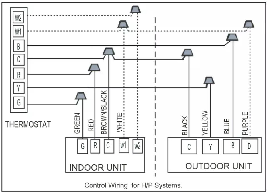
flowchart
graph TD
    subgraph Thermostat
        W2["W2"] -->|Dotted| A1["Indoor Unit"]
        W1["W1"] -->|Dotted| A1
        B["B"] -->|Dotted| A2["Indoor Unit"]
        C["C"] -->|Dotted| A2
        R["R"] -->|Dotted| A2
        Y["Y"] -->|Dotted| A2
        G["G"] -->|Dotted| A2
    end

    subgraph Outdoor Unit
        Green["G"] --> A3["Indoor Unit"]
        Red["R"] --> A3
        Brown/Black["C"] --> A3
        White["w1"] --> A3
        Black["w2"] --> A3
        Yellow["Y"] --> A4["Outdoor Unit"]
        Blue["B"] --> A4
        Purple["D"] --> A4
    end

    A1 -->|Green| B1
    A1 -->|Red| B2
    A1 -->|Brown/Black| B3
    A1 -->|White| B4
    A2 -->|Black| B5
    A2 -->|Yellow| B6
    A2 -->|Blue| B7
    A2 -->|Purple| B8
    B1 --> C["C"]
    B1 --> Y["Y"]
    B2 --> B["B"]
    B2 --> D["D"]
    B3 --> C
    B3 --> Y
    B4 --> C
    B4 --> Y
    B5 --> C
    B5 --> Y
    B6 --> C
    B6 --> Y
    B7 --> C
    B7 --> Y
    B8 --> C
    B8 --> Y

    style Outdoor Unit fill:#f9f,stroke:#333
    style Thermostat fill:#ccf,stroke:#333
Notes:
- Be sure power supply agrees with equipment nameplate.
- Power wiring and grounding of equipment must comply with local codes.
- Low voltage wiring to be No. 18 AWG minimum conductor.
- "----"The electric auxiliary heat connection(option).
- W: Electric auxiliary heat signal.
- W1: The first Electric auxiliary heat signal.
- W2: The second Electric auxiliary heat signal.
- The outdoornit D signal is connect to the Electric auxiliary heat or The first Electric auxiliary heat.
Section 12. Electrical - High Voltage
12.1 High Voltage Power Supply

WARNING
LIVE ELECTRICAL COMPONENTS!
Check the power supply before installation. Ensure that the power supply must be reliably grounded following local, state and National Electrical Codes. If not, for example, if the ground wire is detected charged, installation is prohibited before it is rectified. Otherwise, there is a risk of fire and electric shock, causing physical injury or death.

WARNING
LIVE ELECTRICAL COMPONENTS!
During installation, testing, servicing, and troubleshooting of this product, it may be necessary to work with live electrical components. Failure to follow all electrical safety precautions when exposed to live electrical components could result in death or serious injury.
The high voltage power supply must agree with the equipment nameplate.
Power wiring must comply with national, state, and local codes.
Follow instructions on unit wiring diagram located on the inside of the control box cover and in the Service Facts document included with the unit.
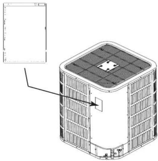
natural_image
Technical line drawing of a large industrial air conditioning unit with grid-patterned roof and mounting base (no text or symbols)12.2 High Voltage Disconnect Switch
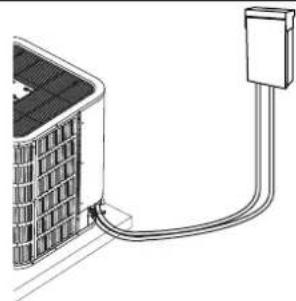
Install a separate disconnect switch at the outdoor unit.
Field provided flexible electrical conduit must be used for high voltage wiring.
natural_image
Diagram of a solar panel connected to a cable with a connector (no text or symbols)12.3 High Voltage Ground
Ground the outdoor unit per national, state, and local code requirements.
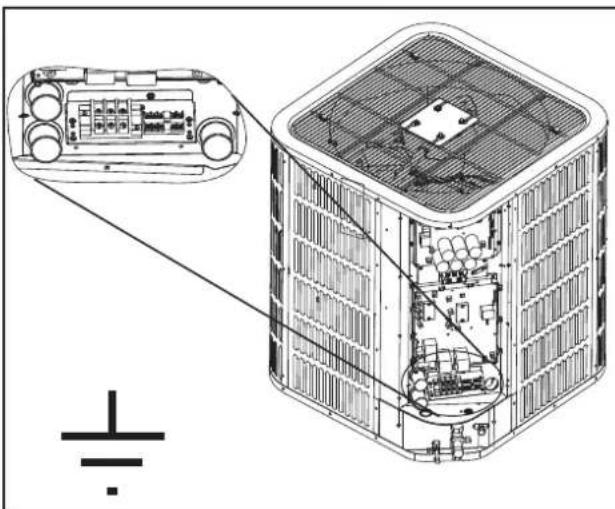
natural_image
Technical line drawing of an air conditioning unit with internal components and a close-up view of the housing (no text or symbols)Section 13. Start Up
13.1 System Start Up
STEP 1 - Ensure Sections 7, 8, 9, 10, 11, 12, and 13 have been completed.
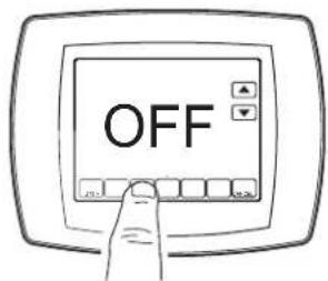
STEP 2 - Set System Thermostat to OFF.
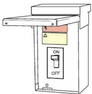
STEP 3 - Turn on disconnect to apply power to the indoor and outdoor units.
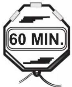
STEP 4 - Wait five (5) minutes before moving to Step 5 if no crankcase heater accessory is used,
Wait one (1) hour before starting the unit if compressor crankcase heater accessory is used and the Outdoor Ambient Temperature is below 70 °F.
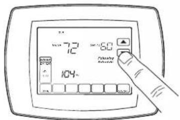
STEP 5 - Set system thermostat to ON.
Section 14. System Charge Adjustment
14.1 charging: weigh-In Method
Weigh-In Method can be used for the Initial installation, or anytime a system charge is being replaced. weigh-In Method can also be used when power is not available to the equipment site or operating conditions (indoor/Outdoor temperatures) are not in range to verify with the subcooling charging method.
| A | B | C |
| Model | Factory Charge | charge multiplier for interconnecting refrigerant tube length |
| All models | (The data on nameplate) | 0.6 oz/ft |
Note: The factory charge in the outdoor unit is sufficient for 15 feet of standard size interconnecting liquid line.
Table 19. New Installations — Calculating additional charge for lineset greater than 15ft
- Total Line Length (ft) = ____ (a)
- Standard Lineset (ft) = 15 (b)
- (a) minus (b) = ____ (c)
- Refrigerant Multiplier = 0.6 oz/ft (d)
- Refrigerant Adder (c*d) = ____(e)*
*If lineset is less than 15 ft, (e) = 0
Table 20. Sealed-System Repairs — calculating charge using the weigh-In method.
- Total Line Length (ft) = ____ (a)
- Standard Lineset (ft) = 15 (b)
- (a) minus (b) = ____ (c)
- Refrigerant Multiplier = 0.6 oz/ft (d)
- Refrigerant Adder (c*d) = ____(e)*
- Factory Charge (namplate) = ____ (f)
- Total System Charge (e+f) = ____
*If lineset is less than 15 ft, (e) = 0
Note: The only mode approved for validating system charge is while in Cooling "Charge Mode". Outdoor Temperature must be between 55°F and 120°F with Indoor Temperature kept between 70°F and 80°F.
14.2 Subcooling charging and refrigerant adjustment in cooling (above 55 °F outdoor temp.)
STEP 1 - Check the outdoor ambient temperatures.
Subcooling (in cooling mode) is the only recommended method of charging above 55^ F outdoor ambient temperatures.
Outdoor Temperature Above 55°F
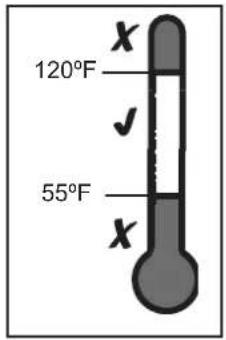
Outdoor Temp1
For outdoor ambient temperatures below 55°F, use weigh-in charge method.
Note: It is important to return in the spring or summer to accurately charge the system in the cooling mode when outdoor ambient temperature is above 55^ F.
Outdoor Temperature Below 55°F
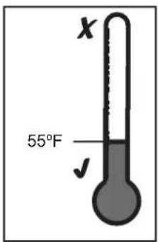
Outdoor Temp2
For best results the indoor temperature should be kept between 70^ F to 80^ F.
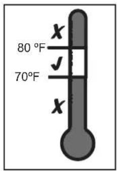
Indoor Temp
STEP 2 - Ensure Sections 7, 8, 9, 10, and 13 have been completed.
STEP 3 - Stabilize the system.
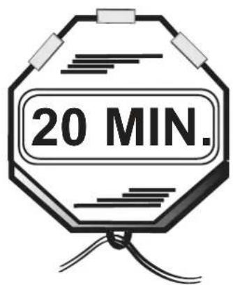
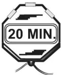
After starting the system in cooling mode, short press "FORCE" button, and "F" symbol appears in 10 minutes, operate the system for a minimum of twenty (20) minutes.
Important: After twenty (20) minutes stabilization period, maintain continuous operation while adjusting refrigerant charge or TXV, after which operate system for a minimum of fi ve (5) minutes for system to stabilize, otherwise repeat step 3.3.
STEP 4 - Calculate superheat value on suction valves(According to form)
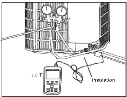
Measured Suction Line Temp. = ____°F
Measured Suction Line Pressure = ____ PSIG
Calculate superheat value = ____°F
Note: Make sure the superheat value of suction valve should be above 12^ F, if the value is lower than this, indoor TXV should be adjusted. If the temperature is higher than 18^ F, we suggest to adjust indoor TXV.
Repeat the steps above.
(If to adjust TXV, steps of adjustment are shown on separate sheet, and repeat this step.)
If the TXV is not adjustable, make sure it works at all times.
| R-410A REFRIGERAN CHART | ||||||||
| SUCTIONTEMP(°F) | FINAL SUPERHEAT(°F) | |||||||
| 8 | 10 12 | 14 16 | 18 20 | 22 | ||||
| SUCTION GAGE PRESSURE (PSI) | ||||||||
| 40 101 | 97 9 | 3 89 | 86 82 | 78 75 | ||||
| 42 105 | 101 | 97 93 | 89 86 | 82 78 | ||||
| 44 110 | 105 | 101 9 | 7 93 | 89 86 | 82 | |||
| 46 114 | 110 | 105 1 | 101 97 | 93 89 | 86 | |||
| 48 118 | 114 | 110 1 | 105 10 | 1 97 | 93 89 | |||
| 50 123 | 118 | 114 1 | 10 105 | 101 | 97 93 | |||
| 52 128 | 123 | 118 1 | 14 110 | 105 | 101 | 97 | ||
| 54 133 | 128 | 123 1 | 18 114 | 110 | 105 | 101 | ||
| 56 138 | 133 | 128 1 | 23 118 | 114 | 110 | 105 | ||
| 58 143 | 138 | 133 1 | 28 123 | 118 | 114 | 110 | ||
| 60 148 | 143 | 138 1 | 33 128 | 123 | 118 | 114 | ||
| 62 153 | 148 | 143 1 | 38 133 | 128 | 123 | 118 | ||
| 64 159 | 153 | 148 1 | 43 138 | 133 | 128 | 123 | ||
| 66 164 | 159 | 153 1 | 48 143 | 138 | 133 | 128 | ||
| 68 170 | 164 | 159 1 | 53 148 | 143 | 138 | 133 | ||
| 70 176 | 170 | 164 1 | 59 153 | 148 | 143 | 138 | ||
| 72 182 | 176 | 170 1 | 64 159 | 153 | 148 | 143 | ||
STEP 5 - Calculate subcooling value on liquid valves(According to form)
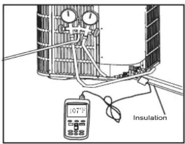
Measured liquid Line Temp = °F
Measured liquid Line Pressure = ____ PSIG
Calculate subcooling value = ____°F
Note: If the subcooling value is lower than the design value, please add refrigerant when the superheat on suction meets the requirement. Repeat the steps above.
| R-410A REFRIGERAN CHART | ||||||||
| LIQUIDTEMP(°C) | FINALSUBCOOLING(°C) | |||||||
| 67 | 89 | 1011 | 1213 | |||||
| LIQUID GAGE PRESSURE (PSI) | ||||||||
| 55 173 | 176 | 179 | 182 | 185 | 188 | 191 | 195 | |
| 60 188 | 191 | 195 | 198 | 201 | 204 | 208 | 211 | |
| 65 204 | 208 | 211 | 215 | 218 | 221 | 225 | 229 | |
| 70 221 | 225 | 229 | 232 | 236 | 239 | 243 | 247 | |
| 75 239 | 243 | 247 | 251 | 255 | 259 | 262 | 266 | |
| 80 259 | 262 | 266 | 270 | 275 | 279 | 283 | 287 | |
| 85 279 | 283 | 287 | 291 | 295 | 300 | 304 | 309 | |
| 90 300 | 304 | 309 | 313 | 318 | 322 | 327 | 331 | |
| 95 322 | 327 | 331 | 336 | 341 | 346 | 351 | 355 | |
| 100 346 | 351 | 355 | 360 | 365 | 370 | 376 | 381 | |
| 105 370 | 376 | 381 | 386 | 391 | 397 | 402 | 407 | |
| 110 397 | 402 | 407 | 413 | 418 | 424 | 430 | 435 | |
| 115 424 | 430 | 435 | 441 | 447 | 453 | 459 | 465 | |
| 120 453 | 459 | 465 | 471 | 477 | 483 | 489 | 496 | |
| 125 483 | 489 | 496 | 502 | 508 | 515 | 521 | 528 | |
| Model 24 36 48 60 | ||||
| Design subcooling | 10^ ± 2^ | 10^ ± 2^ | 8^ ± 2^ | 7^ ± 2^ |
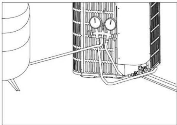
STEP 6 - Adjust refrigerant level to attain proper gage pressure.
Add refrigerant if the design subcooling is lower than the chart value.
- Connect gages to refrigerant bottle and unit as illustrated.
- Purge all hoses.
- Open bottle.
- Stop adding refrigerant when subcooling matches the charging chart Final Subcooling value.
Recover refrigerant if the subcooling is higher than the chart value.
natural_image
Technical line drawing of a mechanical or electrical component with pipes and gauges (no text or symbols)STEP 7 - Stabilize the system.
- Wait 5 minutes for the system condition to stabilize between adjustments.
Note: When the subcooling match the chart, the system is properly charged.
-
Remove gages.
-
Replace service port caps to prevent leaks. Tighten finger tight plus an additional 1/6 turn.
STEP 8 - Record System Information for reference.
Record system pressures and temperatures after charging is complete.
Outdoor model number = ____
Measured Outdoor Ambient = ____ °F
Measured Indoor Ambient = ____ °F
Measured Liquid Line Temp = ____ °F
Measured Suction Line Temp = ____ °F
Liquid Gage Pressure = ____ PSIG
Suction Gage Pressure = ____ PSIG
Section 15 System operation and Troubleshooting
1. Control logic description
- The variable speed system adopts the same 24VAC control as any conventional Heat Pump. - The compressor's speed is controlled based on coil pressures monitored by pressure transducer. To insure stable and adequate capacity, the compressor speed will modulate relative to evaporator pressure during cooling operation and relative to condensing pressure during heating operation. The target pressure can auto-matically adjust based on compressor operation so optimal capacity can be achieved. Target pressure can manually be adjusted (SW4) to achieve improved dehumidification and capacity demands.
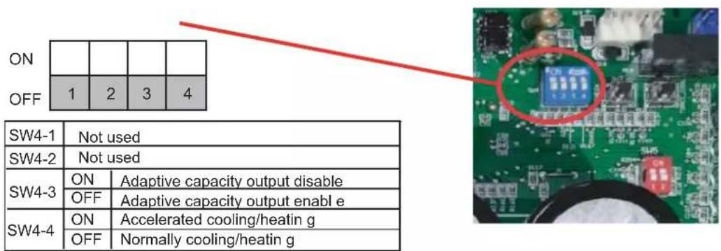
2. Sensor
- T3(Outdoor coil temperature) and T4(ambient temperature, heat pump only) see TABLE A
- T5(compressor discharge temperature) and Tf(IPM radiator temperature) see TABLE B.
• Pressure Transducer see TABLE C.
3. Sensor description
A working T3 Sensor is required for:
- Operating protection (high temp./low temp.)
• Outdoor fan control(cooling)
• Defrost (heat pump only) - Ambient temp forecast (Cooling only)
A working T4 Sensor is required for (Heat pump only):
- Operating condition permission
• Defrosting condition permission
• Outdoor fan control(heating mode, Heat pump only)
A working T5 Sensor is required for:
• Protection(high temp./low temp.)
- Outside Electronic Expansion Valve control (Heat pump only)
A working Tf Sensor is required for:
- Module temp. protection(high temp.)
A working Pressure Transducer (PT) is required for:
- Operating speed control
- Outside Electronic Expansion Valve control (Heat pump only)
• High pressure protection(heating mode, Heat pump only) - Low pressure protection(cooling mode)
4、Defrost description (Heat Pump only)
- The demand defrost control measures the coil temperature with a sensor located on the heat pump coil. A second sensor located outside the outdoor coil is used to measure outdoor ambient temperature.
The demand of defrost is computed by the coil temperature and outdoor ambient temperature, also, by the running time and outdoor ambient temperature, by the running time and high pressure when hing pressure is lower than a certain value.
- Enter defrosting
Any one of three conditions is required to enter defrost:
- The calculated temperature difference between the outdoor temperature(T4) and the coil temperature(T3) is called Delta T. After Delta T is achieved and lasted for 5 minutes.
— T4≥39°F, Delta T=18°F
— T4≥30°F, Delta T=16°F
— T4≥19°F, Delta T=14°F
- After "Minimum Run Time" (MRT) is achieved. MRT is based on outdoor ambient temperature (T4), for example:
— MRT is 4 hours when: T4 < 23°F
— MRT is 2 hours when: 23^ F ≤ T4 < 42^ F
- After the high pressure saturation temperature drops below 82°F for 20 minutes.
- Quit defrosting
-
Defrost will terminate once outdoor coil temperature (T3) reaches 64^ F for a period of 1 minute or defrost time has exceeded 8 minutes.
-
Defrost Termination Settings (SW5) offers different defrost termination options for enhanced defrost for different geographical &/or outdoor conditions.
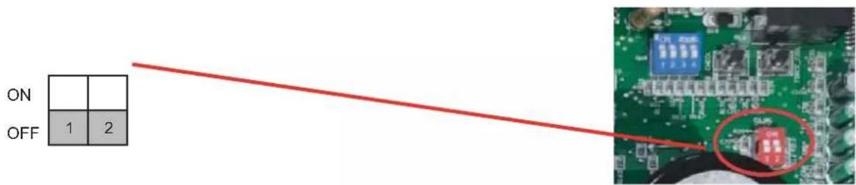
| Defrosting choice | SW5-1 | SW5-2 | Remarks |
| ON | Operating time is reduced by 10% | Defrosting extended for 60 seconds | |
| OFF Normal | Normal | Default | |
| Remarks | Enter defrost | Quit defrost |
- Manual defrosting (Heat Pump only)
-
System must have a call for heat and have been operating for a minimum of 8 minutes.
-
Press "Force" button on inverter board for 6 seconds to begin forced defrost.
-
Wait approximately 40 seconds for defrost to initiate.
-
Once defrost initiates, the display will indicate "dF".
-
Defrost test will terminate automatically, after which the display will indicate running speed.
-
If a second defrost test is required, repeat step 3 after 5 minutes.
5. Compressor Crankcase heater description
Refrigerant migration during the OFF cycle can result in a noisy start up, therefore a crankcase heater (CCH) is used to minimize refrigerant migration thereby minimizing start-up noise and/or bearing "wash out".
All CCHs must be installed on the lower half of the compressor shell. Its purpose is to warm the compressor on the OFF cycle, driving refrigerant from compressor. At initial start-up or after extended shutdown periods, allow CCH to be energized for at least 12 hours prior to compressor operation by applying line voltage to heat pump with thermostat OFF.
• CCH operation energizes:
-
First time line voltage is applied and compressor discharge temperature T5 <104°F.
-
In process of defrosting.
-
Compressor stops running for 4 hours and outdoor ambient temperature T4 <50°F or T5 < 104°F.
• CCH operation de-energizes:
- Compressor discharge temperature T5 ≥ 113°F.
6. Reversing valve introduction (heat pump only)
- Reversing valve energizes at the heating conditions, and cut off at the cooling condition.
7. Protection function introduction
• Outdoor coil temperature protection (T3)
i. If T3 > 143.6°F, compressor is de-energized
ii. If T3 < 129.2°F, compressor is energized
- Ambient temperature protection (T4)
i. If 40^ ≤ T4 < 120^ , unit can operate in cooling
ii. If 5°F ≤ T4 < 86°F, unit can operate in heating
iii. If T4 < 6.8°F, heat pump will provide 24V control to indoor unit energizing electric heat (if installed).
• Discharge Temperature (DT) protection (T5)
i. If DT > 239°F during cooling mode, the compressor will stop.
ii. If DT < 194°F during cooling mode, the compressor will restart.
iii. If DT > 221°F during heating mode, the compressor will stop.
iv. If DT < 167°F during heating mode, the compressor will restart.
- High pressure protection (HPS) (mechanical open/close pressure switch)
i. HPS opens at P > 580 PSIG, the compressor and outdoor fan stop.
ii. HPS closes at P < 435 PSIG, the compressor and outdoor fan restart.
- Low pressure protection (LP)
i. If Low Pressure < 43.5 PSI for 5 minutes during cooling mode, the compressor and outdoor fan will stop. System will attempt to run again after 6 minutes.
- Module (inverter) protection (TF)
i. If TF > 176°F, the compressor and outdoor fan will stop.
ii. If TF<145°F, the compressor and outdoor fan will restart.
Note: In keeping with product improvement, we reserve the right to make changes without notice.
8. Fault code table
| Code Fault Description | |
| E4 Temperature sensor fault(T3, T4, T5, TF) | |
| E5 High/low voltage protection | |
| E6 DC fan motor fault | |
| E7 Compressor discharge sensor(T5) is seated fault | |
| E9 EEPROM fault | |
| Eb System lockup, 2 times (E6) protection in 10 minutes | |
| H0 Communication fault in main control chip | |
| H4 System lockup, 3 times (P6) protection in 60 minutes | |
| H5 System lockup, 5 times (P2) protection in 100 minutes | |
| H8 Pressure transducer(PT) fault | |
| Hb High pressure(PT) protection in Heating | |
| P0 High module radiator temperature (TF)protection | |
| P1 High pressure switch(HPS)protection | |
| P2 Low pressure(PT) Protection in cooling | |
| P3 Compressor over current protection | |
| P4 High compressor discharge temperature(T5) protection | |
| P5 Condensor coil temperature(T3) protection in cooling | |
| P6 The IPM module protection | |
| PH Low discharge superheat protection | |
| F1 High pressure switch(HPS) fault | |
| C3 The condensor coil sensor(T3) is seated fault in cooling | |
| L0-L9 The IPM module protection (the same as P6,only for analysis) | |
| AtL Ambient Temperature Limited | |
| System Protection Status Codes | |
| I- | Indication under charge model |
| L Running indication under T3 limited condition | |
| D Running indication under T5 limited condition | |
| P Running indication under compressor ratio limited condition | |
| F Running indication under Tf limited condition | |
| C Running indication under current limited condition | |
| U Running indication under low voltage limited condition | |
| H Running indication under high pressure(PT) limited condition in heating | |
| A Running indication under return oil model | |
| dF Running indication under defrost model | |
9. Parameter point check table
- To display system parameters, press the "Check" button to index through the series of parameters available. The first time you press on the "Check" button, it will display the sequence, and after 1 second it will display the value of the parameter. If you press the "Check" button again, it will display the next sequence.
- Normal Status, last two digits will display under following conditions
i. Unit not operating(Standby Mode); "outdoor ambient temperature".
ii. Unit operating; displays "compressor operating frequency".
- After 20 seconds on same parameter, display will revert back to normal status.
- If a system protection is active, first digit will display "status code".
| No. | Point check content | Example | Remark |
| 0 | Outdoor unit capacity H3 H3=Heat Pump 3 ton | ||
| 1 | Outdoor unit mode 2 | 0 standby,2 cooling,3 heating | |
| 2 | Outdoor unit set compressor speed | ||
| 3 | Opening of EEV Actual value | ||
| 4 | T3(outdoor coil temp.) (°F) | ||
| 5 | T4 (outdoor ambient temp.) (°F) | ||
| 6 | T5(compressor discharge temp.) (°F) | ||
| 7 | Reserved | ||
| 8 | Te (evaporating temp.) (°F) | ||
| 9 | Tc (condensing temp.) (°F) | ||
| 10 | Tf (module temp.) (°F) | ||
| 11 | Pe (evaporating pressure) (PSI) | ||
| 12 | Pc (condensing pressure) (PSI) | ||
| 13 | Compressor discharge superheat (°F) Actual value | ||
| 14 | Reserved | ||
| 15 | Reserved | ||
| 16 | Compressor current (A) | ||
| 17 | Reserved | ||
| 18 | Fan speed | ||
| 19 | Reserved | ||
| 20 | Reserved | ||
| 21 | Target of the compressor discharge superheat(only useful for heating mode)(☒) | Target Value | |
| 22 | Reserved | ||
| 23 | Last Fault Code | ||
| 24 | Software version | ||
| 25 | Remark“--” |
For 24/36k model
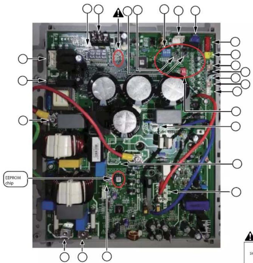
A
NOTE: The photo is just for reference, actual unit will verify.
| No. | Function description | No. | Function description |
| 1 | Compressor wiring terminal | 13 | Temp. controller connecting port |
| 2 | Reactor wiring terminal(connect a reactor between 2 and 3) | 14 | Function dial code SW4 |
| 3 | Reactor wiring terminal(connect a reactor between 2 and 3) | 15 | Spot check button |
| 4 | Defrosting function dial codeSW5 | 16 | Forced operation button |
| 5 | Pressure transducer port | 17 | Reserved |
| 6 | Compressor discharge temp. sensor port | 18 | Digital tube display |
| 7 | Ambient temp. sensor port(HP only) | 19 | Fan control port |
| 8 | Outdoor coil temp. sensor port | 20 | Crankcase heating zone control terminal |
| 9 | Radiator temp.sensor port | 21 | Short wire |
| 10 | High pressure switch port | 22 | Power supply connecting terminal |
| 11 | EEV drive port(HP only) | 23 | Power supply connecting terminal |
| 12 | Reversing valve port(HP only) | 24 | Indicator lamp |
For 48/60k model
Main control board
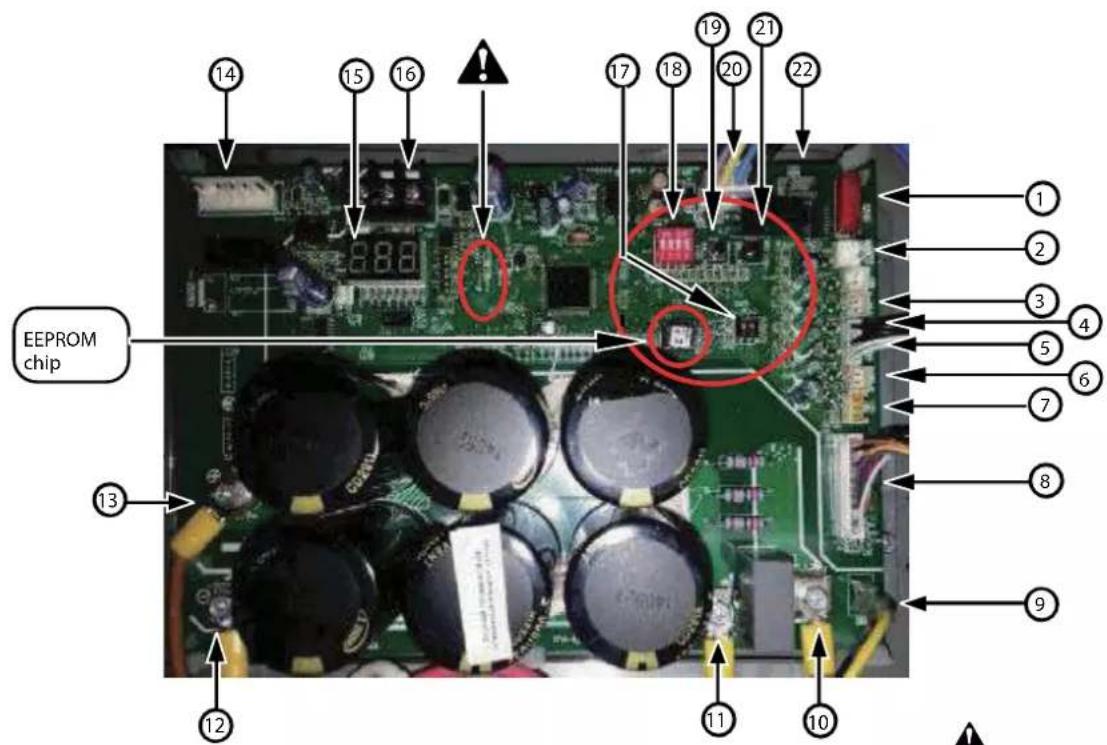
!
NOTE: The photo is just for reference, actual unit will verify.
| No. | Function description | No. | Function description |
| 1 | EEV driving port (HP only) 12 The voltage between 12 and 13 is 380Vdc (Compressor is running ) | ||
| 2 | High pressure switch port 13 The voltage between 12 and 13 is 380Vdc (Compressor is running ) | ||
| 3 | Radiator temp. sensor port | 14 DC motor control port | |
| 4 | Outdoor coil temp. sensor port | 15 Nixie tube display | |
| 5 | Ambient temp. sensor port(HP only) | 16 Reserved | |
| 6 | Compressor discharge temp. sensor port | 17 Defrosting functiondialcode SW5 | |
| 7 | Pressure transducer 18 Function dial code SW4 | ||
| 8 | Connection wire port between main boards 19 Point check button | ||
| 9 | DC motor driving source (15V-P2) 20 Temp. controller connection port | ||
| 10 | The voltage between 10 and 11 is 380Vdc (Compressor is running | 21 Forced operation button | |
| 11 | The voltage between 10 and 11 is 380Vdc (Compressor is running ) | 22 Reversing valve port(HP only) | |
Drive board
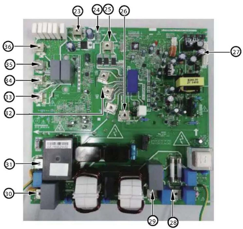
NOTE: The photo is just for reference, actual unit will verify.
| No. | Function desdign | No. | Function description |
| 23 | Connect the cathode of the rectifier bridge | 30 | AC power supply output port |
| 24 DC motor driving source(15V-P2) 31 AC power supply output port | |||
| 25 The voltage between 25 and 26 is 380Vdc (Compressor is running ) 32 Compressor connection terminal | |||
| 26 | The voltage between 25 and 26 is 380Vdc (Compressor is running ) | 33 | The voltage between 33 and 36 is 380Vdc (Compressor is running ) |
| 27 Connection wire port between main boards 34 Reactor L1 wiring terminal | |||
| 28 AC power supply input port 35 Reactor L2 wiring terminal | |||
| 29 AC power supply input port 36 The voltage between 33 and 36 is 380Vdc (Compressor is running) | |||
15. 10 Error code troubleshooting
| Error Code | Description |
| P1 | High pressure switch(HPS)protection |
| P5 | Condenser coil temperature(T3) protection in cooling |
| Hb | High pressure(PT) protection in Heating |
| P3 | Compressor over current protection |
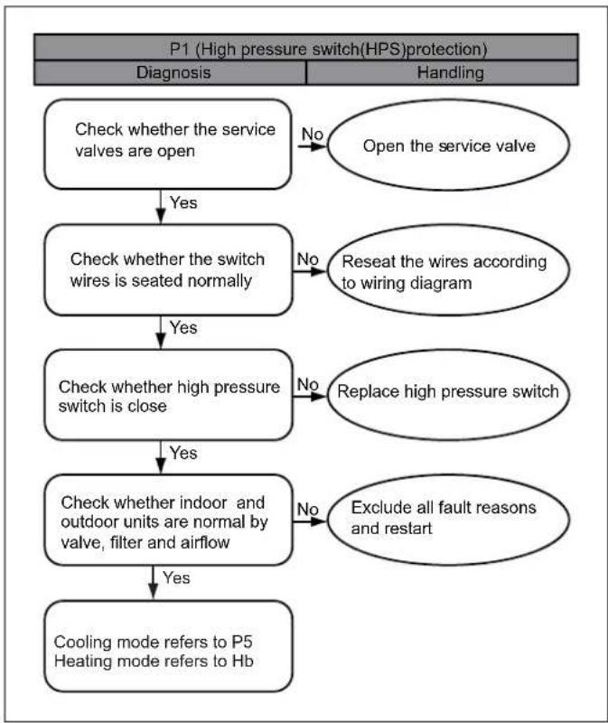
flowchart
graph TD
    A["P1 (High pressure switch(HPS)protection)"] --> B["Diagnosis"]
    A --> C["Handling"]
    B --> D{Check whether the service valves are open}
    D -->|Yes| E["Check whether the switch wires is seated normally"]
    E -->|Yes| F["Check whether high pressure switch is close"]
    F -->|Yes| G["Check whether indoor and outdoor units are normal by valve, filter and airflow"]
    G -->|Yes| H["Cooling mode refers to P5\nHeating mode refers to Hb"]
    G -->|No| I["Open the service valve"]
    E -->|No| J["Reseat the wires according to wiring diagram"]
    F -->|No| K["Replace high pressure switch"]
    G -->|No| L["Exclude all fault reasons and restart"]
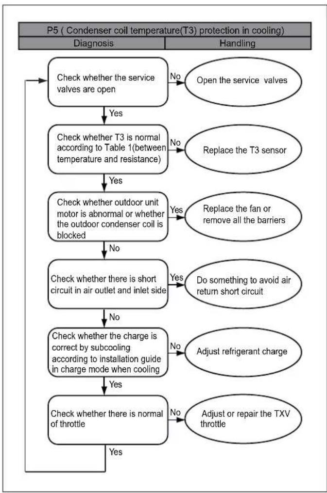
flowchart
graph TD
    A["P5 ( Condenser coil temperature(T3) protection in cooling) "] --> B["Diagnosis"]
    A --> C["Handling"]
    B --> D{Check whether the service valves are open}
    D -->|No| E["Open the service valves"]
    D -->|Yes| F{Check whether T3 is normal according to Table 1(between temperature and resistance)}
    F -->|No| G["Replace the T3 sensor"]
    F -->|Yes| H{Check whether outdoor unit motor is abnormal or whether the outdoor condenser coil is blocked}
    H -->|Yes| I["Replace the fan or remove all the barriers"]
    H -->|No| J{Check whether there is short circuit in air outlet and inlet side}
    J -->|Yes| K["Do something to avoid air return short circuit"]
    J -->|No| L{Check whether the charge is correct by subcooling according to installation guide in charge mode when cooling}
    L -->|No| M["Adjust refrigerant charge"]
    L -->|Yes| N{Check whether there is normal of throttle}
    N -->|No| O["Adjust or repair the TXV throttle"]
    N -->|Yes| P["End"]
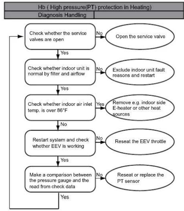
flowchart
graph TD
    A["Hb ( High pressure(PT) protection in Heating )"] --> B["Diagnosis Handling"]
    B --> C{Check whether the service valves are open}
    C -->|No| D["Open the service valve"]
    C -->|Yes| E{Check whether indoor unit is normal by filter and airflow}
    E -->|No| F["Exclude indoor unit fault reasons and restart"]
    E -->|Yes| G{Check whether indoor air inlet temp. is over 86°F}
    G -->|No| H["Restart system and check whether EEV is working"]
    G -->|Yes| I{Remove e.g. indoor side E-heater or other heat sources}
    H -->|No| J["Reseat the EEV throttle"]
    H -->|Yes| K{Make a comparison between the pressure gauge and the read from check data}
    K -->|No| L["Reseat or replace the PT sensor"]
    K -->|Yes| M{Do not check}
| Error Code | Description |
| P0 | High module radiator temperature (TF) protection |
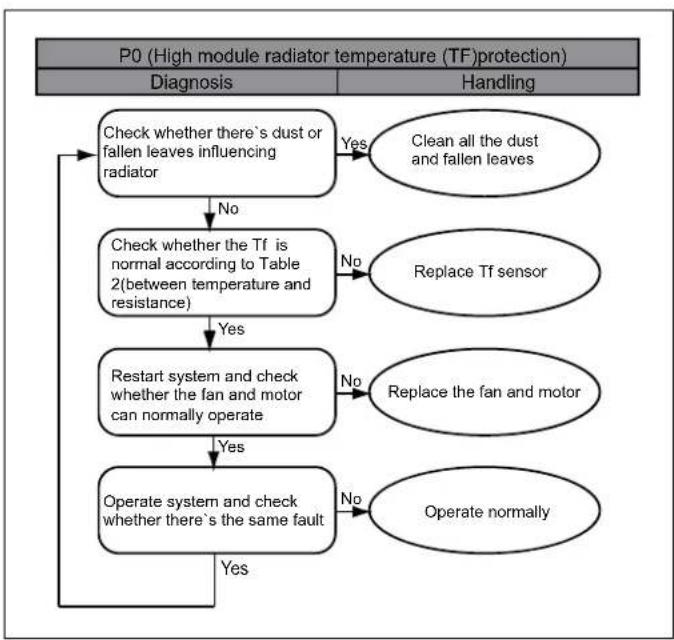
flowchart
graph TD
    A["P0 (High module radiator temperature (TF)protection)"] --> B["Diagnosis"]
    A --> C["Handling"]
    B --> D{Check whether there's dust or fallen leaves influencing radiator}
    D -->|No| E["Check whether the Tf is normal according to Table 2(between temperature and resistance)"]
    E -->|Yes| F["Restart system and check whether the fan and motor can normally operate"]
    F -->|No| G["Replace the fan and motor"]
    F -->|Yes| H["Operate system and check whether there's the same fault"]
    H -->|No| I["Operate normally"]
    H -->|Yes| J["End"]
    D -->|Yes| K["Clean all the dust and fallen leaves"]
    E -->|No| L["Replace Tf sensor"]
    G --> M["No"]
    I --> N["No"]
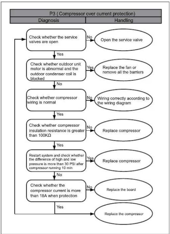
flowchart
graph TD
    A["P3 (Compressor over current protection)"] --> B["Diagnosis"]
    A --> C["Handling"]
    B --> D{Check whether the service valves are open}
    D -->|No| E["Open the service valve"]
    D -->|Yes| F["Check whether outdoor unit motor is abnormal and the outdoor condenser coil is blocked"]
    F -->|No| G["Check whether compressor wiring is normal"]
    F -->|Yes| H["Replace the fan or remove all the barriers"]
    G -->|No| I["Wiring correctly according to the wiring diagram"]
    G -->|Yes| J["Check whether compressor insulation resistance is greater than 100KΩ"]
    J -->|No| K["Replace compressor"]
    J -->|Yes| L["Restart system and check whether the difference of high and low pressure is more than 30 PSI after compressor running 10 min"]
    L -->|No| M["Check whether the compressor current is more than 18A when protection"]
    L -->|Yes| N["Replace the board"]
    M -->|No| O["Replace the compressor"]
    M -->|Yes| P["Replace the compressor"]
| Error Code | Description |
| P2 | Low pressure(PT) Protection in cooling |
| H5 | System lockup, 5 times (P2) protection in 100 minutes |
| P4 | High compressor discharge temperature(T5) protection |
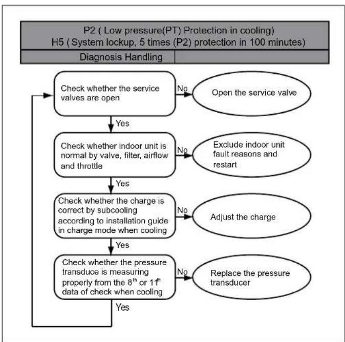
flowchart
graph TD
    A["P2 (Low pressure(PT) Protection in cooling)<br>H5 (System lockup, 5 times (P2) protection in 100 minutes)"] --> B["Diagnosis Handling"]
    B --> C{Check whether the service valves are open}
    C -->|No| D["Open the service valve"]
    C -->|Yes| E{Check whether indoor unit is normal by valve, filter, airflow and throttle}
    E -->|No| F["Exclude indoor unit fault reasons and restart"]
    E -->|Yes| G{Check whether the charge is correct by subcooling according to installation guide in charge mode when cooling}
    G -->|No| H["Adjust the charge"]
    G -->|Yes| I{Check whether the pressure transduce is measuring properly from the 8th or 11th data of check when cooling}
    I -->|No| J["Replace the pressure transducer"]
    I -->|Yes| K{Check whether the pressure transduce is measuring properly from the 8th or 11th data of check when cooling}
    K -->|No| D
    K -->|Yes| L["End"]
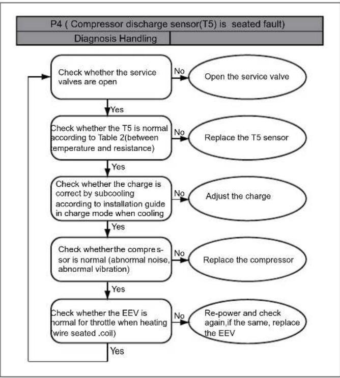
flowchart
graph TD
    A["P4 ( Compressor discharge sensor(T5) is seated fault) "] --> B["Diagnosis Handling"]
    B --> C{Check whether the service valves are open}
    C -->|No| D["Open the service valve"]
    C -->|Yes| E{Check whether the T5 is normal according to Table 2(between temperature and resistance)}
    E -->|No| F["Replace the T5 sensor"]
    E -->|Yes| G{Check whether the charge is correct by subcooling according to installation guide in charge mode when cooling}
    G -->|No| H["Adjust the charge"]
    G -->|Yes| I{Check whether the compressor is normal (abnormal noise, abnormal vibration)}
    I -->|No| J["Replace the compressor"]
    I -->|Yes| K{Check whether the EEV is normal for throttle when heating (wire seated .coil)}
    K -->|No| L["Re-power and check again,if the same, replace the EEV"]
    K -->|Yes| M{Check whether the VEE is normal for throttle when heating (wire seated .coil)}
    M -->|No| N["Re-power and check again,if the same, replace the EEV"]
Error Code Description
PH Low discharge superheat protection
Error Code Description
E4 Temperature sensor fault(T3, T4, T5, TF)
H8 Pressure transducer(PT) fault
F1 High pressure switch(HPS) fault
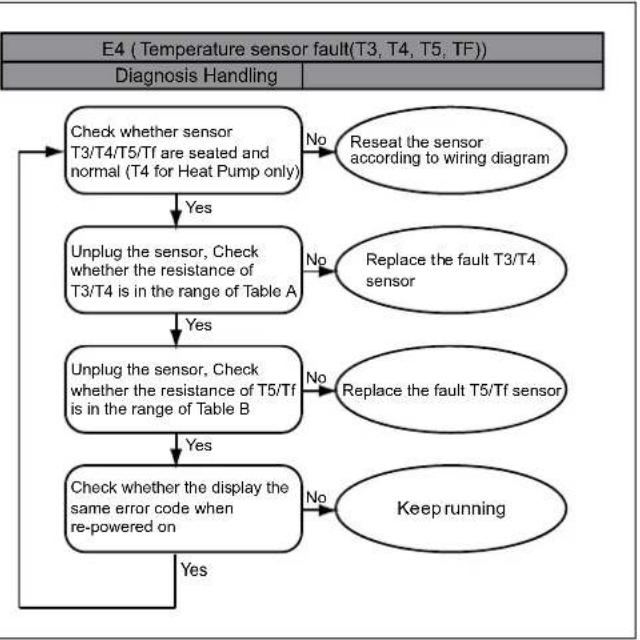
flowchart
graph TD
    A["E4 (Temperature sensor fault(T3, T4, T5, TF))"]
    B["Diagnosis Handling"] --> C["Check whether sensor T3/T4/T5/Tf are seated and normal (T4 for Heat Pump only)"]
    C -->|No| D["Reseat the sensor according to wiring diagram"]
    C -->|Yes| E["Unplug the sensor, Check whether the resistance of T3/T4 is in the range of Table A"]
    E -->|No| F["Replace the fault T3/T4 sensor"]
    E -->|Yes| G["Unplug the sensor, Check whether the resistance of T5/Tf is in the range of Table B"]
    G -->|No| H["Replace the fault T5/Tf sensor"]
    G -->|Yes| I["Check whether the display the same error code when re-powered on"]
    I -->|No| J["Keep running"]
    I -->|Yes| K["End"]
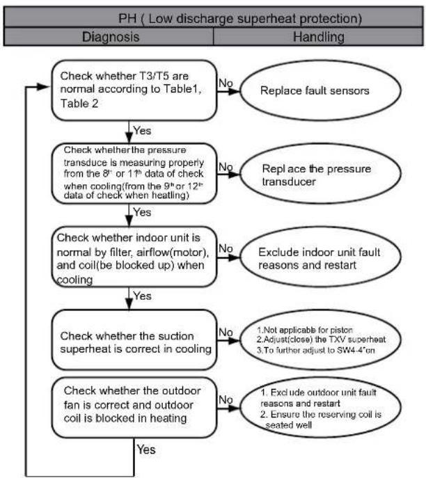
flowchart
graph TD
    A["PH (Low discharge superheat protection)"] --> B["Diagnosis"]
    A --> C["Handling"]
    B --> D{Check whether T3/T5 are normal according to Table1, Table 2}
    D -->|Yes| E["Check whether the pressure transduce is measuring properly from the 8° or 11° data of check when cooling(from the 9° or 12° data of check when heating)"]
    E -->|No| F["Replace fault sensors"]
    E -->|Yes| G{Check whether indoor unit is normal by filter, airflow(motor), and coil(be blocked up) when cooling}
    G -->|Yes| H["Check whether the suction superheat is correct in cooling"]
    G -->|No| I["Exclude indoor unit fault reasons and restart"]
    H -->|Yes| J["Check whether the outdoor fan is correct and outdoor coil is blocked in heating"]
    H -->|No| K["1. Not applicable for piston\n2. Adjust(close) the TXV superheat\n3. To further adjust to SW4.4"on"]
    J -->|Yes| L["Check whether the outdoor fan is correct and outdoor coil is blocked in heating"]
    J -->|No| M["1. Exclude outdoor unit fault reasons and restart\n2. Ensure the reserving coil is seated well"]
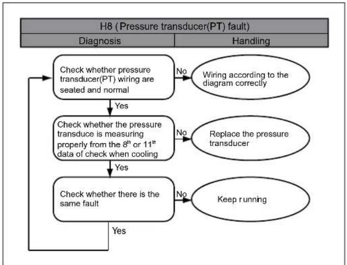
flowchart
graph TD
    A["H8 (Pressure transducer(PT) fault)"] --> B["Diagnosis"]
    A --> C["Handling"]
    B --> D{Check whether pressure transducer(PT) wiring are seated and normal}
    D -->|No| E["Wiring according to the diagram correctly"]
    D -->|Yes| F{Check whether the pressure transduce is measuring properly from the 8th or 11th data of check when cooling}
    F -->|No| G["Replace the pressure transducer"]
    F -->|Yes| H{Check whether there is the same fault}
    H -->|No| I["Keep running"]
    H -->|Yes| J{Check whether there is the same fault}
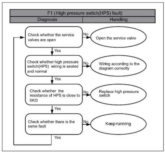
flowchart
graph TD
    A["F1 (High pressure switch(HPS) fault)"] --> B["Diagnosis"]
    A --> C["Handling"]
    B --> D{Check whether the service valves are open}
    D -->|No| E["Open the service valve"]
    D -->|Yes| F{Check whether high pressure switch(HPS) wiring is seated and normal}
    F -->|No| G["Wiring according to the diagram correctly"]
    F -->|Yes| H{Check whether the resistance of HPS is close to 0KΩ}
    H -->|No| I["Replace high pressure switch"]
    H -->|Yes| J{Check whether there is the same fault}
    J -->|No| K["Keep running"]
    J -->|Yes| L{Diagnosis?}

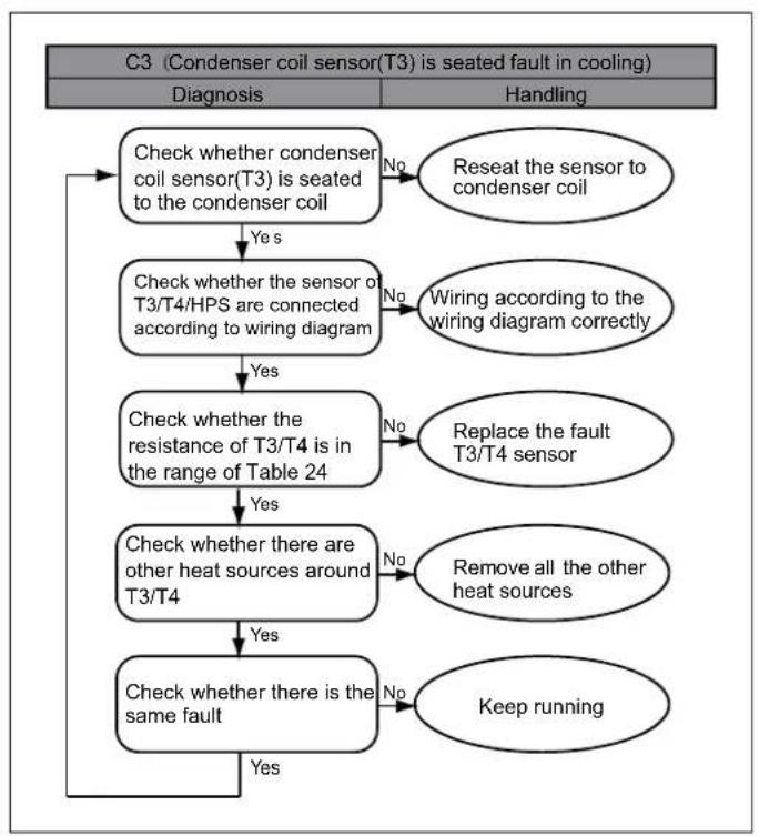
flowchart
graph TD
    A["C3 (Condenser coil sensor(T3) is seated fault in cooling)"] --> B["Diagnosis"]
    A --> C["Handling"]
    B --> D{Check whether condenser coil sensor(T3) is seated to the condenser coil}
    D -->|No| E["Reseat the sensor to condenser coil"]
    D -->|Yes| F{Check whether the sensor of T3/T4/HPS are connected according to wiring diagram}
    F -->|No| G["Wiring according to the wiring diagram correctly"]
    F -->|Yes| H{Check whether the resistance of T3/T4 is in the range of Table 24}
    H -->|No| I["Replace the fault T3/T4 sensor"]
    H -->|Yes| J{Check whether there are other heat sources around T3/T4}
    J -->|No| K["Remove all the other heat sources"]
    J -->|Yes| L{Check whether there is the same fault}
    L -->|No| M["Keep running"]
    L -->|Yes| N["End"]

flowchart
graph TD
    A["E7 (Compressor discharge sensor(T5) is seated fault)"] --> B["Diagnosis"]
    A --> C["Handling"]
    B --> D{Check whether condenser coil sensor(T5) is seated to the condenser coil}
    D -->|Yes| E["Check whether the sensor of T3/T5 are connected according to wiring diagram"]
    E --> F{Check whether the resistance of T3/T5 is in the range of Table 24 and Table 25}
    F -->|Yes| G["Check whether there are other heat sources around T3/T5"]
    F -->|No| H["Replace the fault T3/T5 sensor"]
    G --> I{Check whether there is the same fault}
    I -->|Yes| J["Check whether there is the same fault"]
    I -->|No| K["Keep running"]
    D -->|No| L["Reseat the sensor to discharge tube"]
    E -->|No| M["Wiring according to the wiring diagram correctly"]
    F -->|No| N["Remove all the other heat sources"]
| Error Code | Description |
| E6 DC fan motor fault | |
| Eb System lockup, 2 times (E6) protection in 10 minutes | |
When E6 appears occasionally, you don't need to do anything, the system will restart automatically after 6 minutes, of course, if you check the system of running, it will be better. When Eb appears, you need to check the motor.
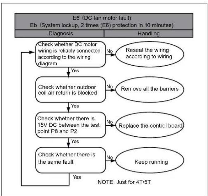
flowchart
graph TD
    A["E6 (DC fan motor fault)\neb (System lockup, 2 times (E6) protection in 10 minutes)"] --> B["Diagnosis"]
    A --> C["Handling"]
    B --> D{Check whether DC motor wiring is reliably connected according to the wiring diagram}
    D -->|Yes| E["Check whether outdoor coil air return is blocked"]
    E -->|No| F["Reseat the wiring according to wiring"]
    E -->|Yes| G{Check whether there is 15V DC between the test point P8 and P2}
    G -->|No| H["Remove all the barriers"]
    G -->|Yes| I{Check whether there is the same fault}
    I -->|No| J["Replace the control board"]
    I -->|Yes| K["Keep running"]
    J --> L["NOTE: Just for 4T/5T"]
Error Code Description
E9 EEPROM fault
H0 Communication fault in main control chip
E5 High/low voltage protection
When E9/H0/E5 appears occasionally, and the system restart to run normally after power supply again, you don't need to do anything. Otherwise, you need to check the system.
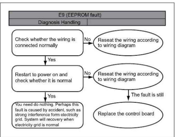
flowchart
graph TD
    A["E9 (EEPROM fault)"] --> B["Diagnosis Handling"]
    B --> C{Check whether the wiring is connected normally}
    C -->|No| D["Reseat the wiring according to wiring diagram"]
    C -->|Yes| E["Restart to power on and check whether it is normal"]
    E -->|No| F["Reseat the wiring according to wiring diagram"]
    E -->|Yes| G["You need do nothing. Perhaps this fault is caused by accident, such as strong interference form electricity grid. System will recovery when electricity grid is normal"]
    F --> H["The fault is still"]
    G --> I["Replace the control board"]
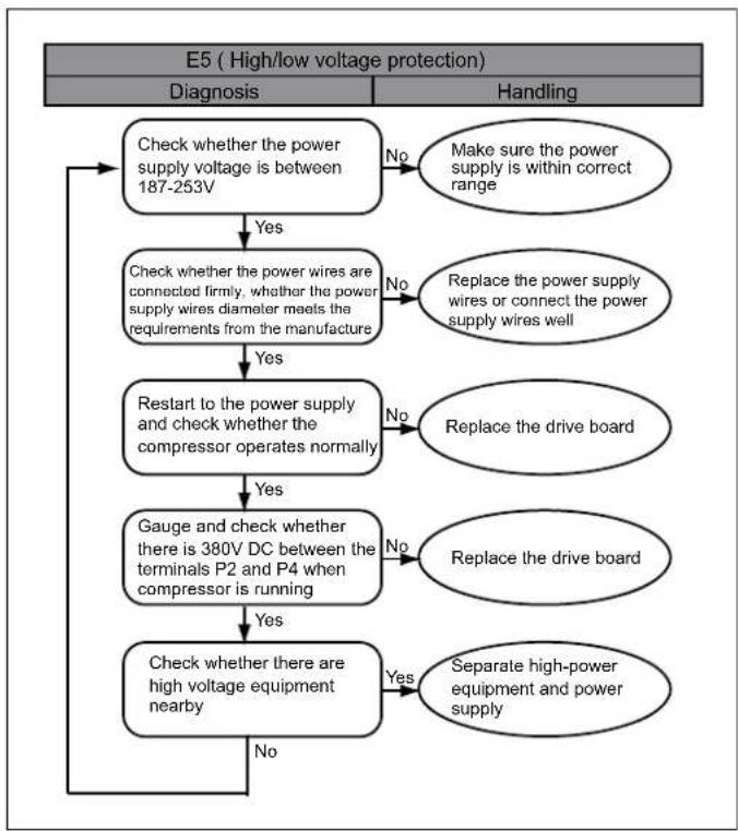
flowchart
graph TD
    A["E5 (High/low voltage protection)"] --> B["Diagnosis"]
    A --> C["Handling"]
    B --> D{Check whether the power supply voltage is between 187-253V}
    D -->|No| E["Make sure the power supply is within correct range"]
    D -->|Yes| F["Check whether the power wires are connected firmly, whether the power supply wires diameter meets the requirements from the manufacture"]
    F -->|No| G["Replace the power supply wires or connect the power supply wires well"]
    F -->|Yes| H["Restart to the power supply and check whether the compressor operates normally"]
    H -->|No| I["Replace the drive board"]
    H -->|Yes| J["Gauge and check whether there is 380V DC between the terminals P2 and P4 when compressor is running"]
    J -->|No| K["Replace the drive board"]
    J -->|Yes| L["Check whether there are high voltage equipment nearby"]
    L -->|Yes| M["Separate high-power equipment and power supply"]
    L -->|No| N["End"]
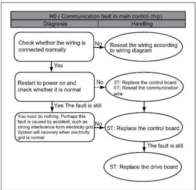
flowchart
graph TD
    A["H0 ( Communication fault in main control chip) "] --> B["Diagnosis"]
    A --> C["Handling"]
    B --> D{Check whether the wiring is connected normally}
    D -->|No| E["Reseat the wiring according to wiring diagram"]
    D -->|Yes| F["Restart to power on and check whether it is normal"]
    F -->|No| G["3T: Replace the control board\n5T: Reseat the communication wire"]
    F -->|Yes| H["You need do nothing. Perhaps this fault is caused by accident, such as strong interference form electricity grid\nSystem will recover when electricity grid is normal"]
    G --> I["5T: Replace the control board"]
    I --> J["The fault is still"]
    I --> K["5T: Replace the drive board"]
| Error Code | Description |
| P6 IPM module protection | |
| H4 System lockup, 3 times (P6/L0-9) protection in 60 minutes | |
| L0-L9 IPM module protection (the same as P6, only for analysis) | |
When P6/L0-L9 appears occasionally, you don't need to do anything, the system will restart automatically after 6 minutes, of course, if you check the system of running, it will be better.
| Error Code | Description |
| AtL Ambient Temperature Limited | |
NOTE: When the ambient temperature returns to within the operating range, the system recovery automatically.
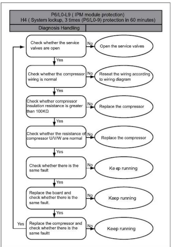
flowchart
graph TD
    A["P6/L0-L9 (IPM module protection)<br>H4 (System lockup, 3 times (P6/L0-9) protection in 60 minutes)"] --> B["Diagnosis Handling"]
    B --> C{Check whether the service valves are open}
    C -->|No| D["Open the service valves"]
    C -->|Yes| E{Check whether the compressor wiring is normal}
    E -->|No| F["Reseat the wiring according to wiring diagram"]
    E -->|Yes| G{Check whether compressor insulation resistance is greater than 100KΩ}
    G -->|No| H["Replace the compressor"]
    G -->|Yes| I{Check whether the resistance of compressor U/V/W are normal}
    I -->|No| J["Replace the compressor"]
    I -->|Yes| K{Check whether there is the same fault}
    K -->|No| L["Keep running"]
    K -->|Yes| M{Replace the board and check whether there is the same fault}
    M -->|No| N["Keep running"]
    M -->|Yes| O{Replace the compressor and check whether there is the same fault}
    O -->|No| P["Keep running"]
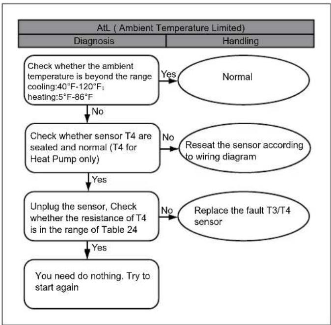
flowchart
graph TD
    A["AtL ( Ambient Temperature Limited) "] --> B["Diagnosis"]
    A --> C["Handling"]
    B --> D{Check whether the ambient temperature is beyond the range cooling: 40°F-120°F; heating: 5°F-86°F}
    D -->|No| E["Check whether sensor T4 are seated and normal (T4 for Heat Pump only)"]
    E -->|Yes| F["Unplug the sensor, Check whether the resistance of T4 is in the range of Table 24"]
    F -->|No| G["Replace the fault T3/T4 sensor"]
    G --> H["You need do nothing. Try to start again"]
    D -->|Yes| I["Normal"]
    E -->|No| J["Reseat the sensor according to wiring diagram"]
TABLE A
| TEMP F | TEMP C | RESISTANCE kΩ | VOLTS DC | TEMP F | TEMP C | RESISTANCE kΩ | VOLTS DC |
| -5 | -20.6 | 107.732 | 4.65 | 90 | 32.2 | 7.225 | 2.36 |
| 0 | -17.8 | 93.535 | 4.6 | 95 | 35 | 6.401 | 2.21 |
| 5 | -15 | 79.521 | 4.54 | 100 | 37.8 | 5.683 | 2.07 |
| 10 | -12.2 | 67.795 | 4.47 | 105 | 40.6 | 5.057 | 1.93 |
| 15 | -9.4 | 57.948 | 4.39 | 110 | 43.3 | 4.509 | 1.79 |
| 20 | -6.7 | 49.652 | 4.3 | 115 | 46.1 | 4.028 | 1.67 |
| 25 | -3.9 | 42.645 | 4.21 | 120 | 48.9 | 3.606 | 1.55 |
| 30 | -1.1 | 36.710 | 4.1 | 125 | 51.7 | 3.233 | 1.43 |
| 40 | 4.4 | 27.386 | 3.86 | 130 | 54.4 | 2.902 | 1.32 |
| 45 | 7.2 | 23.732 | 3.73 | 135 | 57.2 | 2.610 | 1.22 |
| 50 | 10 | 20.610 | 3.59 | 140 | 60 | 2.350 | 1.13 |
| 55 | 12.8 | 17.939 | 3.45 | 145 | 62.8 | 2.119 | 1.04 |
| 60 | 15.6 | 15.648 | 3.3 | 150 | 65.6 | 1.914 | 0.96 |
| 65 | 18.3 | 13.681 | 3.15 | 155 | 68.3 | 1.731 | 0.88 |
| 70 | 21.1 | 11.987 | 2.99 | 160 | 71.1 | 1.574 | 0.82 |
| 75 | 23.9 | 10.527 | 2.83 | 165 | 73.9 | 1.416 | 0.75 |
| 80 | 26.7 | 9.265 | 2.67 | 170 | 76.7 | 1.276 | 0.68 |
| 85 | 29.4 | 8.172 | 2.52 |
TABLE B
| TEMP F | TEMP C | RESISTANCE kΩ | VOLTS DC TEM | P F TEMP C | RESISTANC kΩ | VOLTS DC | |
| -5 -20 | 6 600.134 | 4.93 140 60 13.643 | 3.14 | ||||
| 0 | -17.8 | 505.551 | 4.92 | 145 | 62.8 | 12.359 | 3.03 |
| 5 | -15 | 427.463 | 4.91 | 150 | 65.6 | 11.214 | 2.91 |
| 10 | -12.2 | 362.739 | 4.89 | 155 | 68.3 | 10.227 | 2.8 |
| 15 | -9.4 | 308.891 | 4.87 | 160 | 71.1 | 9.308 | 2.68 |
| 20 | -6.7 | 265.398 | 4.85 | 165 | 73.9 | 8.485 | 2.56 |
| 25 | -3.9 | 227.481 | 4.83 | 170 | 76.7 | 7.746 | 2.45 |
| 30 | -1.1 | 195.601 | 4.8 | 175 | 79.4 | 7.105 | 2.34 |
| 35 | 1.7 | 168.707 | 4.77 | 180 | 82.2 | 6.504 | 2.23 |
| 40 | 4.4 | 146.695 | 4.74 | 185 | 85 | 5.963 | 2.13 |
| 45 | 7.2 | 127.258 | 4.7 | 190 | 87.8 | 5.474 | 2.02 |
| 50 | 10 | 110.707 | 4.66 | 195 | 90.6 | 5.032 | 1.92 |
| 55 | 12.8 | 96.572 | 4.61 | 200 | 93.3 | 4.645 | 1.83 |
| 60 | 15.6 | 84.465 | 4.56 | 205 | 96.1 | 4.28 | 1.73 |
| 65 | 18.3 | 74.411 | 4.51 | 210 | 98.9 | 3.949 | 1.64 |
| 70 | 21.1 | 65.408 | 4.45 | 215 | 101.7 | 3.648 | 1.56 |
| 75 | 23.9 | 57.634 | 4.39 | 220 | 104.4 | 3.383 | 1.48 |
| 80 | 26.7 | 50.904 | 4.32 | 225 | 107.2 | 3.133 | 1.4 |
| 85 | 29.4 | 45.258 | 4.24 | 230 | 110 | 2.904 | 1.32 |
| 90 | 32.2 | 40.152 | 4.16 | 235 | 112.8 | 2.694 | 1.25 |
| 95 | 35 | 35.699 | 4.08 | 240 | 115.6 | 2.503 | 1.18 |
| 100 | 37.8 | 31.807 | 3.99 | 245 | 118.3 | 2.334 | 1.12 |
| 105 | 40.6 | 28.398 | 3.89 | 250 | 121.1 | 2.172 | 1.06 |
| 110 | 43.3 | 25.506 | 3.8 | 255 | 123.9 | 2.024 | 1 |
| 115 | 46.1 | 22.861 | 3.7 | 260 | 126.7 | 1.888 | 0.95 |
| 120 | 48.9 | 20.529 | 3.59 | 265 | 129.4 | 1.767 | 0.9 |
| 125 | 51.7 | 18.47 | 3.48 | 270 | 132.2 | 1.651 | 0.85 |
| 130 | 54.4 | 16.708 | 3.37 | 275 | 135 | 1.544 | 0.8 |
| 135 | 57.2 | 15.085 | 3.26 | 280 | 137.8 | 1.446 | 0.76 |
TABLE C1 (For AC model)
| NSK-BD0201 V=1.38*PSIG*10+0.5 | |||||||
| No. V No | V | Te Pe Te | Pe | ||||
| "I" | PSIG | "I" | PSIG | ||||
| 1 1.04 | -3 39 47 2.00 36 | 109 | |||||
| 2 1.07 | -6 41 48 2.02 37 | 111 | |||||
| 3 1.10 | -4 43 49 2.05 37 | 113 | |||||
| 4 1.11 | -3 44 50 2.08 38 | 115 | |||||
| 5 1.13 | -2 45 51 2.11 39 | 117 | |||||
| 6 1.14 | -1 47 52 2.14 40 | 119 | |||||
| 7 1.16 | 0 48 53 2.16 41 | 121 | |||||
| 8 1.17 | 1 49 54 2.19 42 | 123 | |||||
| 9 1.19 | 1 50 55 2.22 43 | 125 | |||||
| 10 1.21 | 2 51 56 2.25 44 | 127 | |||||
| 11 1.22 | 3 52 57 2.28 45 | 129 | |||||
| 12 1.24 | 4 54 58 2.31 46 | 131 | |||||
| 13 1.26 | 5 55 59 2.34 46 | 134 | |||||
| 14 1.27 | 6 56 60 2.37 47 | 136 | |||||
| 15 1.29 | 7 57 61 2.40 48 | 138 | |||||
| 16 1.31 | 8 59 62 2.44 49 | 140 | |||||
| 17 1.33 | 9 60 63 2.47 50 | 143 | |||||
| 18 1.35 | 10 61 64 2.50 51 | 145 | |||||
| 19 1.37 | 10 63 65 2.53 52 | 147 | |||||
| 20 1.38 | 1 64 66 2.56 53 | 150 | |||||
| 21 1.40 | 1 2 66 67 2.60 54 | 152 | |||||
| 22 1.42 | 1 3 67 68 2.63 55 | 155 | |||||
| 23 1.44 | 1 4 68 69 2.67 56 | 157 | |||||
| 24 1.46 | 1 5 70 70 2.70 57 | 160 | |||||
| 25 1.48 | 1 6 71 71 2.74 58 | 162 | |||||
| 26 1.50 | 1 7 73 72 2.77 59 | 165 | |||||
| 27 1.52 | 1 8 74 73 2.81 60 | 167 | |||||
| 28 1.54 | 1 9 76 74 2.84 61 | 170 | |||||
| 29 1.57 | 1 9 77 75 2.88 62 | 172 | |||||
| 30 1.59 | 2 0 79 76 2.92 63 | 175 | |||||
| 31 1.61 | 2 1 80 77 2.95 64 | 178 | |||||
| 32 1.63 | 2 2 82 78 2.99 65 | 181 | |||||
| 33 1.65 | 2 3 84 79 3.03 66 | 183 | |||||
| 34 1.68 | 2 4 85 80 3.07 67 | 186 | |||||
| 35 1.70 | 2 5 87 81 3.10 68 | 189 | |||||
| 36 1.72 | 2 6 89 82 3.14 69 | 192 | |||||
| 37 1.75 | 2 7 90 83 3.18 70 | 195 | |||||
| 38 1.77 | 2 8 92 84 3.22 71 | 197 | |||||
| 39 1.79 | 2 8 94 85 3.26 72 | 200 | |||||
| 40 1.82 | 2 9 96 86 3.30 73 | 203 | |||||
| 41 1.84 | 3 0 97 87 3.35 74 | 206 | |||||
| 42 1.87 | 3 1 99 88 3.39 75 | 209 | |||||
| 43 1.89 | 3 2 101 89 3.43 | 212 | |||||
| 44 1.92 | 3 3 103 90 3.47 | 216 | |||||
| 45 1.94 | 3 4 105 91 3.51 | 219 | |||||
| 46 1.97 | 3 5 107 92 3.56 | 222 | |||||
TABLE C2 (For HP model)
| NSK-BD035I V=7.88*PSIG*10+0.5 | |||||||||||
| No. | V | Te/Tc Pe | Pc Te/Tc Pe | Pc Te/Tc Pe/Pc No. | V | No. | V | ||||
| T | PSIG | T | PSIG | T | PSIG | ||||||
| 1 0.69 | -22 24 56 1.37 | 37 111 11 | 1 2.54 86 2 | 58 | |||||||
| 2 0.70 | -20 26 57 1.39 | 37 113 11 | 2 2.56 87 2 | 62 | |||||||
| 3 0.72 | -18 28 58 1.40 | 38 115 11 | 3 2.59 88 2 | 66 | |||||||
| 4 0.73 | -17 29 59 1.42 | 39 117 11 | 4 2.62 89 2 | 69 | |||||||
| 5 0.75 | -15 31 60 1.43 | 40 119 11 | 5 2.65 90 2 | 73 | |||||||
| 6 0.76 | -13 33 61 1.45 | 41 121 11 | 6 2.68 91 2 | 77 | |||||||
| 7 0.78 | -11 35 62 1.47 | 42 123 11 | 7 2.71 91 2 | 80 | |||||||
| 8 0.79 | -9 37 63 1.48 | 43 125 118 | 2.74 92 284 | ||||||||
| 9 0.81 | -8 39 64 1.50 | 44 127 119 | 2.77 93 288 | ||||||||
| 10 0.82 | -6 41 65 1.52 | 45 129 120 | 2.80 94 292 | ||||||||
| 11 0.84 | -4 43 66 1.53 | 46 131 121 | 2.83 95 295 | ||||||||
| 12 0.85 | -3 44 67 1.55 | 46 134 122 | 2.86 96 299 | ||||||||
| 13 0.86 | -2 45 68 1.57 | 47 136 123 | 2.89 97 303 | ||||||||
| 14 0.87 | -1 47 69 1.59 | 48 138 124 | 2.92 98 307 | ||||||||
| 15 0.88 | 0 | 48 70 1.61 49 | 140 125 2 | 95 99 311 | |||||||
| 16 0.89 | 1 | 49 71 1.62 50 | 143 126 2 | 98 100 315 | |||||||
| 17 0.89 | 1 | 50 72 1.64 51 | 145 127 3 | 102 100 319 | |||||||
| 18 0.90 | 2 | 51 73 1.66 52 | 147 128 3 | 105 101 324 | |||||||
| 19 0.91 | 3 | 52 74 1.68 53 | 150 129 3 | 108 102 328 | |||||||
| 20 0.92 | 4 | 54 75 1.70 54 | 152 130 3 | 112 103 332 | |||||||
| 21 0.93 | 5 | 55 76 1.72 55 | 155 131 3 | 115 104 336 | |||||||
| 22 0.94 | 6 | 56 77 1.74 55 | 157 132 3 | 118 105 340 | |||||||
| 23 0.95 | 7 | 57 78 1.76 56 | 160 133 3 | 122 106 345 | |||||||
| 24 0.96 | 8 | 59 79 1.78 57 | 162 134 3 | 125 107 349 | |||||||
| 25 0.97 | 9 | 60 80 1.80 58 | 165 135 3 | 129 108 353 | |||||||
| 26 0.98 | 10 61 81 1.82 | 59 167 136 | 3.32 109 358 | ||||||||
| 27 0.99 | 10 63 82 1.84 | 60 170 137 | 3.36 109 362 | ||||||||
| 28 1.01 | 11 64 83 1.86 | 61 172 138 | 3.39 110 367 | ||||||||
| 29 1.02 | 12 66 84 1.88 | 62 175 139 | 3.43 111 371 | ||||||||
| 30 1.03 | 13 67 85 1.90 | 63 178 140 | 3.46 112 376 | ||||||||
| 31 1.04 | 14 68 86 1.92 | 64 181 141 | 3.50 113 381 | ||||||||
| 32 1.05 | 15 70 87 1.94 | 64 183 142 | 3.54 114 385 | ||||||||
| 33 1.06 | 16 71 88 1.97 | 65 186 143 | 3.57 115 390 | ||||||||
| 34 1.07 | 17 73 89 1.99 | 66 189 144 | 3.61 116 395 | ||||||||
| 35 1.09 | 18 74 90 2.01 | 67 192 145 | 3.65 117 400 | ||||||||
| 36 1.10 | 19 76 91 2.03 | 68 195 146 | 3.69 118 405 | ||||||||
| 37 1.11 | 19 77 92 2.06 | 69 197 147 | 3.73 118 409 | ||||||||
| 38 1.12 | 20 79 93 2.08 | 70 200 148 | 3.77 119 414 | ||||||||
| 39 1.13 | 21 80 94 2.10 | 71 203 149 | 3.80 120 419 | ||||||||
| 40 1.15 | 22 82 95 2.13 | 72 206 150 | 3.84 121 424 | ||||||||
| 41 1.16 | 23 84 96 2.15 | 73 209 151 | 3.88 122 430 | ||||||||
| 42 1.17 | 24 85 97 2.17 | 73 212 152 | 3.93 123 435 | ||||||||
| 43 1.19 | 25 87 98 2.20 | 74 216 153 | 3.97 124 440 | ||||||||
| 44 1.20 | 26 89 99 2.22 | 75 219 154 | 4.01 125 445 | ||||||||
| 45 1.21 | 27 90 100 2.25 | 76 222 155 | 4.05 126 450 | ||||||||
| 46 1.23 | 28 92 101 2.27 | 77 225 156 | 4.09 127 456 | ||||||||
| 47 1.24 | 28 94 102 2.30 | 78 228 157 | 4.13 127 461 | ||||||||
| 48 1.25 | 29 96 103 2.32 | 79 231 158 | 4.18 128 466 | ||||||||
| 49 1.27 | 30 97 104 2.35 | 80 235 159 | 4.22 129 472 | ||||||||
| 50 1.28 | 31 99 105 2.38 | 81 238 160 | 4.26 130 477 | ||||||||
| 51 1.30 | 32 101 106 | 2.40 82 241 | 161 4.31 131 | 483 | |||||||
| 52 1.31 | 33 103 107 | 2.43 82 245 | 162 4.35 132 | 489 | |||||||
| 53 1.33 | 34 105 108 | 2.45 83 248 | 163 4.39 133 | 494 | |||||||
| 54 1.34 | 35 107 109 | 2.48 84 252 | 164 4.44 134 | 500 | |||||||
| 55 1.36 | 36 109 110 | 2.51 85 255 | 165 4.48 135 | 506 | |||||||
| SYSTEM FAULTS | ||||||||||||||||||||||||||||||||||||||||||||||||||||||||||||||||||||||||||||||||||||||||||||||||||||||||||||||||||||||||||||||||||||||||||||||||||||||||||||||||||||||||||||||||||||||||||||||||||||||||||||||||||||||||||||||||||||||||||||||||||||||||||||||||||||||||||||||||||||||||||||||||||||||||||||||||||||||||||||||||||||||||||||||||||||||||||||||||||||||||||||||||||||||||||||||||||||||||||||||||||||||||||||||||||||||||||||||||||||||||||||||||||||||||
| POWER OUTPUT OF SHEET IN VALUE (MIPS) | LOW NOTING AREA ON THERMOSTAT | CONTROL BOARD OR WRES | INDEFICIENT COMP | RESID AIRFLOW | RESO D AIRFLOW | REF. UNDERACHARGE | REF. OR RESTRICTIONS | STOCK OPEN OF NEED TO ADJUST | EV OR COIL DEF | REV OR COIL DEF | SERVICE VALVE LEAVING | PT SENSOR DEF | T3 SENSOR DEF | T4 SENSOR DEF | T5 SENSOR DEF | T6 SENSOR DEF | HFS SENSOR DEF | |||||||||||||||||||||||||||||||||||||||||||||||||||||||||||||||||||||||||||||||||||||||||||||||||||||||||||||||||||||||||||||||||||||||||||||||||||||||||||||||||||||||||||||||||||||||||||||||||||||||||||||||||||||||||||||||||||||||||||||||||||||||||||||||||||||||||||||||||||||||||||||||||||||||||||||||||||||||||||||||||||||||||||||||||||||||||||||||||||||||||||||||||||||||||||||||||||||||||||||||||||||||||||||||||||||||||||||||||||||||
| SYSTEM | Display shows nothing | C | P | S | ||||||||||||||||||||||||||||||||||||||||||||||||||||||||||||||||||||||||||||||||||||||||||||||||||||||||||||||||||||||||||||||||||||||||||||||||||||||||||||||||||||||||||||||||||||||||||||||||||||||||||||||||||||||||||||||||||||||||||||||||||||||||||||||||||||||||||||||||||||||||||||||||||||||||||||||||||||||||||||||||||||||||||||||||||||||||||||||||||||||||||||||||||||||||||||||||||||||||||||||||||||||||||||||||||||||||||||||||||||||||||||||||||||
| H | P | S | ||||||||||||||||||||||||||||||||||||||||||||||||||||||||||||||||||||||||||||||||||||||||||||||||||||||||||||||||||||||||||||||||||||||||||||||||||||||||||||||||||||||||||||||||||||||||||||||||||||||||||||||||||||||||||||||||||||||||||||||||||||||||||||||||||||||||||||||||||||||||||||||||||||||||||||||||||||||||||||||||||||||||||||||||||||||||||||||||||||||||||||||||||||||||||||||||||||||||||||||||||||||||||||||||||||||||||||||||||||||||||||||||||||||
| System won't start | C | P | P | S | S | |||||||||||||||||||||||||||||||||||||||||||||||||||||||||||||||||||||||||||||||||||||||||||||||||||||||||||||||||||||||||||||||||||||||||||||||||||||||||||||||||||||||||||||||||||||||||||||||||||||||||||||||||||||||||||||||||||||||||||||||||||||||||||||||||||||||||||||||||||||||||||||||||||||||||||||||||||||||||||||||||||||||||||||||||||||||||||||||||||||||||||||||||||||||||||||||||||||||||||||||||||||||||||||||||||||||||||||||||||||||||||||||||||
| HH | P | P | S | S | ||||||||||||||||||||||||||||||||||||||||||||||||||||||||||||||||||||||||||||||||||||||||||||||||||||||||||||||||||||||||||||||||||||||||||||||||||||||||||||||||||||||||||||||||||||||||||||||||||||||||||||||||||||||||||||||||||||||||||||||||||||||||||||||||||||||||||||||||||||||||||||||||||||||||||||||||||||||||||||||||||||||||||||||||||||||||||||||||||||||||||||||||||||||||||||||||||||||||||||||||||||||||||||||||||||||||||||||||||||||||||||||||||||
| Capacity is insufficiency | C | P | P | P | P | S | S | S | S | |||||||||||||||||||||||||||||||||||||||||||||||||||||||||||||||||||||||||||||||||||||||||||||||||||||||||||||||||||||||||||||||||||||||||||||||||||||||||||||||||||||||||||||||||||||||||||||||||||||||||||||||||||||||||||||||||||||||||||||||||||||||||||||||||||||||||||||||||||||||||||||||||||||||||||||||||||||||||||||||||||||||||||||||||||||||||||||||||||||||||||||||||||||||||||||||||||||||||||||||||||||||||||||||||||||||||||||||||||||||||||||||
| H | P | P | P | P | S | S | S | S | ||||||||||||||||||||||||||||||||||||||||||||||||||||||||||||||||||||||||||||||||||||||||||||||||||||||||||||||||||||||||||||||||||||||||||||||||||||||||||||||||||||||||||||||||||||||||||||||||||||||||||||||||||||||||||||||||||||||||||||||||||||||||||||||||||||||||||||||||||||||||||||||||||||||||||||||||||||||||||||||||||||||||||||||||||||||||||||||||||||||||||||||||||||||||||||||||||||||||||||||||||||||||||||||||||||||||||||||||||||||||||||||||
| Display is not normal | C | P | ||||||||||||||||||||||||||||||||||||||||||||||||||||||||||||||||||||||||||||||||||||||||||||||||||||||||||||||||||||||||||||||||||||||||||||||||||||||||||||||||||||||||||||||||||||||||||||||||||||||||||||||||||||||||||||||||||||||||||||||||||||||||||||||||||||||||||||||||||||||||||||||||||||||||||||||||||||||||||||||||||||||||||||||||||||||||||||||||||||||||||||||||||||||||||||||||||||||||||||||||||||||||||||||||||||||||||||||||||||||||||||||||||||||
| H | P | |||||||||||||||||||||||||||||||||||||||||||||||||||||||||||||||||||||||||||||||||||||||||||||||||||||||||||||||||||||||||||||||||||||||||||||||||||||||||||||||||||||||||||||||||||||||||||||||||||||||||||||||||||||||||||||||||||||||||||||||||||||||||||||||||||||||||||||||||||||||||||||||||||||||||||||||||||||||||||||||||||||||||||||||||||||||||||||||||||||||||||||||||||||||||||||||||||||||||||||||||||||||||||||||||||||||||||||||||||||||||||||||||||||||
| Cool when heating requirement | H | P | S | |||||||||||||||||||||||||||||||||||||||||||||||||||||||||||||||||||||||||||||||||||||||||||||||||||||||||||||||||||||||||||||||||||||||||||||||||||||||||||||||||||||||||||||||||||||||||||||||||||||||||||||||||||||||||||||||||||||||||||||||||||||||||||||||||||||||||||||||||||||||||||||||||||||||||||||||||||||||||||||||||||||||||||||||||||||||||||||||||||||||||||||||||||||||||||||||||||||||||||||||||||||||||||||||||||||||||||||||||||||||||||||||||||||
| REFRIGERANT CIRCUIT | P1 | C | P | P | S | P | ||||||||||||||||||||||||||||||||||||||||||||||||||||||||||||||||||||||||||||||||||||||||||||||||||||||||||||||||||||||||||||||||||||||||||||||||||||||||||||||||||||||||||||||||||||||||||||||||||||||||||||||||||||||||||||||||||||||||||||||||||||||||||||||||||||||||||||||||||||||||||||||||||||||||||||||||||||||||||||||||||||||||||||||||||||||||||||||||||||||||||||||||||||||||||||||||||||||||||||||||||||||||||||||||||||||||||||||||||||||||||||||||||
| H | P | S | P | P | ||||||||||||||||||||||||||||||||||||||||||||||||||||||||||||||||||||||||||||||||||||||||||||||||||||||||||||||||||||||||||||||||||||||||||||||||||||||||||||||||||||||||||||||||||||||||||||||||||||||||||||||||||||||||||||||||||||||||||||||||||||||||||||||||||||||||||||||||||||||||||||||||||||||||||||||||||||||||||||||||||||||||||||||||||||||||||||||||||||||||||||||||||||||||||||||||||||||||||||||||||||||||||||||||||||||||||||||||||||||||||||||||||||
| P3 | C | P | P | S | P | |||||||||||||||||||||||||||||||||||||||||||||||||||||||||||||||||||||||||||||||||||||||||||||||||||||||||||||||||||||||||||||||||||||||||||||||||||||||||||||||||||||||||||||||||||||||||||||||||||||||||||||||||||||||||||||||||||||||||||||||||||||||||||||||||||||||||||||||||||||||||||||||||||||||||||||||||||||||||||||||||||||||||||||||||||||||||||||||||||||||||||||||||||||||||||||||||||||||||||||||||||||||||||||||||||||||||||||||||||||||||||||||||||
| H | P | S | P | P | S | S | S | S | S | S | S | S | S | S | S | S | S | S | S | S | S | S | S | S | S | S | S | S | S | S | S | S | S | S | S | S | S | S | S | S | S | S | S | S | S | S | S | S | S | S | S | S | S | S | S | SP | SP | SP | SP | SP | SP | SP | SP | SP | SP | SP | SP | SP | SP | SP | SP | SP | SP | SP | SP | SP | SP | SP | SP | SP | SP | SP | SP | SP | SP | SP | SP | SP | SP | SP | SP | SP | SP | SP | SP | SP | SP | SP | SP | SP | SP | SP | SP | SP | SP | S | SP | SP | SP | SP | SP | SP | SP | SP | SP | SP | SP | SP | SP | SP | SP | SP | SP | SP | SP | SP | SP | SP | SP | SP | SP | SP | SP | SP | SP | SP | SP | SP | SP | SP | SP | SP | SP | SP | SP | SP | SP | SP | SP | SP | SP | SP | SP | SP | S | S | S | S | S | S | S | S | S | S | S | S | S | S | S | S | S | S | S | S | S | S | S | S | S | S | S | S | S | S | S | S | S | S | S | S | S | S | S | S | S | S | S | S | S | S | S | S | S | SS | S | S | S | S | S | S | S | S | S | S | S | S | S | S | S | S | S | S | S | S | S | S | S | S | S | S | S | S | S | S | S | S | S | S | S | S | S | S | S | S | S | S | S | S | S | S | S | S | S | T | S | S | S | S | S | S | S | S | S | S | S | S | S | S | S | S | S | S | S | S | S | S | S | S | S | S | S | S | S | S | S | S | S | S | S | S | S | S | S | S | S | S | S | S | S | S | S | S | S | |||||||||||||||||||||||||||||||||||||||||||||||||||||||||||||||||||||||||||||||||||||||||||||||||||||||||||||||||||||||||||||||||||||||||||||||||||||||||
| P5 | C | P | P | S | S | S | S | S | S | S | S | S | S | S | S | S | S | S | S | S | S | S | S | S | S | S | S | S | S | S | S | S | S | S | S | S | S | S | S | S | S | S | S | S | S | S | S | S | S | S | S | S | $ | S | S | S | S | S | S | S | S | S | S | S | S | S | S | S | S | S | S | S | S | S | S | S | S | S | S | S | S | S | S | S | S | S | S | S | S | S | S | S | S | S | S | S | S | S | S | S | S | S | P | P | P | P | P | P | P | P | P | P | P | P | P | P | P | P | P | P | P | P | P | P | P | P | P | P | P | P | P | P | P | P | P | P | P | P | P | P | P | P | P | P | P | P | P | P | P | P | P | P | PP | PP | PP | PP | PP | PP | PP | PP | PP | PP | PP | PP | PP | PP | PP | PP | PP | PP | PP | PP | PP | PP | PP | PP | PP | PP | PP | PP | PP | PP | PP | PP | PP | PP | PP | PP | PP | PP | PP | PP | PP | PP | PP | PP | PP | PP | PP | PP | PP | PP | P | P | P | P | PP | PP | PP | PP | PP | PP | PP | PP | PP | PP | PP | PP | PP | PP | PP | PP | PP | PP | PP | PP | PP | PP | PP | PP | PP | PP | PP | PP | PP | PP | PP | PP | PP | PP | PP | PP | PP | PP | PP | PP | PP | PP | PP | PP | PP | P | P | P | PP | PP | PP | PP | PP | PP | PP | PP | PP | PP | PP | PP | PP | PP | PP | PP | PP | PP | PP | PP | PP | PP | PP | PP | PP | PP | PP | PP | PP | PP | PP | PP | PP | PP | PP | PP | PP | PP | PP | PP | PP | PP | PP | PP | PP | PP | P | P | P | PP | P | PP | PP | PP | PP | PP | PP | PP | PP | PP | PP | PP | PP | PP | PP | PP | PP | PP | PP | PP | PP | PP | PP | PP | PP | PP | PP | PP | PP | PP | PP | PP | PP | PP | PP | PP | PP | PP | PP | PP | PP | PP | PP | PP | PP | PP | PP | PP | PP | P | S | S | S | S | S | S | S | S | S | S | S | S | S | S | S | S | S | S | S | S | S | S | S | S | S | S | S | S | S | S | S | S | S | S | S | S | S | S | S | S | S | S | S | S | S | S | S | S | T | T | T | T | T | T | T | T | T | T | T | T | T | T | T | T | T | T | T | T | T | T | T | T | T | T | T | T | T | T | T | T | T | T | T | T | T | T | T | T | T | T | T | T | T | T | T | T | T | T | U** | C P S H P S H P S H P S H P S H P S H P S H P S H P S H P S H P S H P S H P S H P S H P S H P S H P S H P S H P S H P S H P S H P S H P S H P S H P S H P S H P S H P S H P S H P S H P S H P S H P S H P S H H P S H P S H P S H P S H P S H P S H P S H P S H P S H P S H P S H P S H P S H P S H P S H P S H P S H P S H P S H P S H P S H P S H P S H P S H P S H P S H P S H P S H P S H P S H P S H P S H P S S H P S H P S H P S H P S H P S H P S H P S H P S H P S H P S H P S H P S H P S H P S H P S H P S H P S H P S H P S H P S H P S H P S H P S H P S H P S H P S H P S H P S H P S H P S H P S H P S H P P H P S H P S H P S H P S H P S H P S H P S H P S H P S H P S H P S H P S H P S H P S H P S H P S H P S H P S H P S H P S H P S H P S H P S H P S H P S H P S H P S H P S H P S H P S H P S H P S H P S I P P H P S H P S H P S H P S H P S H P S H P S H P S H P S H P S H P S H P S H P S H P S H P S H P S H P S H P S H P S H P S H P S H P S H P S H P S H P S H P S H P S H P S H P S H P S H P S H P S H H P P H P P H P P H P P H P P H P P H P P H P P H P P H P P H P P H P P H P P H P P H P P H P P H P P H P P H P P H P P H P P H P P H P P H P P H P P H P P H P P H P P H P P H P P H P P H P P H P P H P P I P P H P P H P P H P P H P P H P P H P P H P P H P P H P P H P P H P P H P P H P P H P P H P P H P P H P P H P P H P P H P P H P P H P P H P P H P P H P P H P P H P P H P P H P P H P P H P P H P P H F* * * * * * * * * * * * * * * * * * * * * * * * * * * * * * * * * * * * * * * * * * * * * * * * * * * * * * * * * * * * * * * * * * * * * * * * * * * * * * * * * * * * * * * * * * * * * * * * * * * * * 10000000000000000000000000000000000000000000000000000000000000000000000000000000000000000000000000000 10000000000000000000000000000000000000000000000000000000000000000000000000000000000000000000000000 1 1 1 1 1 1 1 1 1 1 1 1 1 1 1 1 1 1 1 1 1 1 1 1 1 1 1 1 1 1 1 1 1 1 1 1 1 1 1 1 1 1 1 1 1 1 1 1 1 1 2 2 2 2 2 2 2 2 2 2 2 2 2 2 2 2 2 2 2 2 2 2 2 2 2 2 2 2 2 2 2 2 2 2 2 2 2 2 2 2 2 2 2 2 2 2 2 2 2 2 3 3 3 3 3 3 3 3 3 3 3 3 3 3 3 3 3 3 3 3 3 3 3 3 3 3 3 3 3 3 3 3 3 3 3 3 3 3 3 3 3 3 3 3 3 3 3 3 3 3 4 4 4 4 4 4 4 4 4 4 4 4 4 4 4 4 4 4 4 4 4 4 4 4 4 4 4 4 4 4 4 4 4 4 4 4 4 4 4 4 4 4 4 4 4 4 4 4 4 4 5 5 5 5 5 5 5 5 5 5 5 5 5 5 5 5 5 5 5 5 5 5 5 5 5 5 5 5 5 5 5 5 5 5 5 5 5 5 5 5 5 5 5 5 5 5 5 5 5 5 6 6 6 6 6 6 6 6 6 6 6 6 6 6 6 6 6 6 6 6 6 6 6 6 6 6 6 6 6 6 6 6 6 6 6 6 6 6 6 6 6 6 6 6 6 6 6 6 6 6 7 7 7 7 7 7 7 7 7 7 7 7 7 7 7 7 7 7 7 7 7 7 7 7 7 7 7 7 7 7 7 7 7 7 7 7 7 7 7 7 7 7 7 7 7 7 7 7 7 7 8 8 8 8 8 8 8 8 8 8 8 8 8 8 8 8 8 8 8 8 8 8 8 8 8 8 8 8 8 8 8 8 8 8 8 8 8 8 8 8 8 8 8 8 8 8 8 8 8 8 9 9 9 9 9 9 9 9 9 9 9 9 9 9 9 9 9 9 9 9 9 9 9 9 9 9 9 9 9 9 9 9 9 9 9 9 9 9 9 9 9 9 9 9 9 9 9 9 9 9 10000000000000000000000000000000000000000000000000000000000000000000000000000000000000000000000000100000000000000000000000000000000000000000000000000000000000000000000000000000000000000000000000000101011111111111111111111111111111111111111111111111111111111111111111111111111111111111111111111111111112111111111111111111111111111111111111111111111111111111111111111111111111111111111111111111111111111011111111111111111111111111111111111111111111111111111111111111111111111111111111111111111111111112122222222222222222222222222222222222222222222222222222222222222222222222222222222222222222222222222223222222222222222222222222222222222222222222222222222222222222222222222222222222222222222222222222222B B E B E B E B E B E B E B E B E B E B E B E B E B E B E B E B E B E B E B E B E B E B E B E B E B E B E B E B E B E B E B E B E B E B E B E B E B E B E B E B E B E B E B E B E B E B E B E B E B E B E B B E B E B E B E B E B E B E B E B E B E B E B E B E B E B E B E B E B E B E B E B E B E B E B E B E B E B E B E B E B E B E B E B E B E B E B E B E B E B E B E B E B E B E B E B E B E B E B E B E BE B E B E B E B E B E B E B E B E B E B E B E B E B E B E B E B E B E B E B E B E B E B E B E B E B E B E B E B E B E B E B E B E B E B E B E B E B E B E B E B E B E B E B E B E B E B E B E B E B E BEB B E B E B E B E B E B E B E B E B E B E B E B E B E B E B E B E B E B E B E B E B E B E B E B E B E B E B E B E B E B E B E B E B E B E B E B E B E B E B E B E B E B E B E B E B E B E B E B E B E BEE B E B E B E B E B E B E B E B E B E B E B E B E B E B E B E B E B E B E B E B E B E B E B E B E B E B E B E B E B E B E B E B E B E B E B E B E B E B E B E B E B E B E B E B E B E B E B E B E B E BES A P O C O N O C O N O C O N O C O N O C O N O C O N O C O N O C O N O C O N O C O N O C O | ||
C-cooling H-Heating P-Primary Causes S-Secondary Causes
Comp.-Compressor RES.-Restrictions REF.-Refrigeration DEF.-Defective CIR.-Circuit EEV-Electronic expansion valve REV.-Reversing Valve PT-Pressure
Transducer T3-Outdoor coil temp, sensor T4-Ambient temp, sensor T5-Comp. discharge temp, sensor Tf-Module radiator fin temp, sensor HPS-High pressure switch
RES I.D. AIRFLOW - Perhaps failure of fan mot or or fan capacitor or filter
RES O.D. AIRFLOW - Perhaps failure of fan motor or fan capacitor or recirculation or blocking coil
RES O.D. RADIATOR-Perhaps failure of blocking radiator
- Air conditioning & Heating
- Installer's Guide
- Condensing Units
- Table of Contents
- Section 1. Safety
- CAUTION
- WARNING
- HAZARDOUS VOLTAGE!
- REFRIGERANT OIL!
- HIGH CURRENT LEAKAGE!
- CONTAINS REFRIGERANT!
- GROUNDING REQUIRED!
- CUTION
- INDOOR UNIT REQUIRED!
- SERVICE VALVES!
- BRAZING REQUIRED!
- HOT SURFACE!
- Section 2. Unit Location Considerations
- Unit Dimensions
- Refrigerant Piping Limits
- Location Restrictions
- Cold Climate Considerations (Heat Pump Only)
- Section 3. Unit Preparation
- Prepare The Unit For Installation
- Section 4. Setting the Unit
- LIVE ELECTRICAL COMPONENTS!
- Pad Installation
- IMPORTANT NOTE:
- X 3/8" Self Tapping Screws (Don't Exceed 3/8" long)
- Section 5. Refrigerant Line Considerations
- Refrigerant Line and Service Valve Connection Sizes
- Required Refrigerant Line Length
- Refrigerant Line Insulation
- Reuse Existing Refrigerant Lines
- Section 6. Refrigerant Line Routing
- Precautions
- Section 7. Refrigerant Line Brazing
- Braze The Refrigerant Lines
- Section 8. Refrigerant Line Leak Check
- Check For Leaks
- Section 9. Evacuation
- Evacuate the Refrigerant Lines and Indoor Coil
- Section 10. Service Valves
- Open the Service Valves
- Section 11. Electrical - Low Voltage
- Low Voltage Maximum Wire Length
- Low Voltage Hook-up Diagrams
- Notes:
- Section 12. Electrical - High Voltage
- High Voltage Power Supply
- High Voltage Disconnect Switch
- High Voltage Ground
- Section 13. Start Up
- System Start Up
- Section 14. System Charge Adjustment
- charging: weigh-In Method
- Subcooling charging and refrigerant adjustment in cooling (above 55 °F outdoor temp.)
- STEP 1 - Check the outdoor ambient temperatures.
- STEP 2 - Ensure Sections 7, 8, 9, 10, and 13 have been completed.
- STEP 3 - Stabilize the system.
- STEP 4 - Calculate superheat value on suction valves(According to form)
- STEP 5 - Calculate subcooling value on liquid valves(According to form)
- Section 15 System operation and Troubleshooting
- Control logic description
- Sensor
- Sensor description
- 4、Defrost description (Heat Pump only)
- Compressor Crankcase heater description
- Reversing valve introduction (heat pump only)
- Protection function introduction
- Fault code table
- Parameter point check table
- For 48/60k model
- 10 Error code troubleshooting
- Error Code Description
Brand : Daizuki
Model : CXN1836-WN1
Category : Air conditioner