
SWE-8 - Audio Equipment Crestron - Free user manual and instructions
Find the device manual for free SWE-8 Crestron in PDF.

| Product Type | Eight-zone unamplified expander for Sonnex multiroom audio system |
| Brand | Crestron |
| Model | SWE-8 |
| Dimensions (Height) | 1.72 in (44 mm) without feet |
| Dimensions (Width) | 19.00 in (483 mm) with rack ears; 17.30 in (440 mm) without ears |
| Dimensions (Depth) | 10.19 in (259 mm) |
| Weight | 5.0 lbs (2.3 kg) |
| Power Supply | 24 V DC, 2 A regulated universal power pack included (100-240 V AC, 50/60 Hz) |
| Power Consumption | 41 Btu/h |
| Operating Temperature | 41° to 104°F (5° to 40°C) |
| Humidity | 10% to 90% RH (non-condensing) |
| Audio Input | Sonnex Link (64-channel digital audio, 48 utilized) |
| Audio Outputs | 4 unbalanced RCA (line-level), 4 balanced 5-pin terminal block (line-level), 4 S/PDIF coaxial (digital), 8 Crestron Home CAT5 balanced (all zones) |
| Frequency Response | 20 Hz to 20 kHz, ±0.5 dB |
| Total Harmonic Distortion + Noise | < 0.003% (S/PDIF), < 0.005% (analog) |
| Signal-to-Noise Ratio | >106 dB (S/PDIF), >100 dB (analog), A-weighted |
| Digital Signal Processing | 5-band graphic or parametric EQ, volume, bass, treble, balance, loudness, mute, mono summing, tone profiles |
| Output Bussing | Multiple zones can be grouped; volume offset adjustment per zone |
| Mounting | Freestanding or 1U 19-inch rack-mountable (feet and rack ears included) |
| Chassis Material | Metal with black finish, vented sides; front panel with polycarbonate label overlay |
| Maintenance | Clean with dry cloth only; do not use near water |
| Safety Compliance | FCC Class B, CE, IC; Class I construction; requires earthing ground |
| Included Accessories | Power pack, rack ears, rubber feet, 5-pin terminal blocks, documentation |
| Available Accessories (sold separately) | ABAR-1 CAT5 Balanced Audio Receiver, AUD-EXT audio extenders, DM-CBL-8G CAT5e cable, S-EXT1-S fiber extender, SWAMP-24X8 system |
Frequently Asked Questions - SWE-8 Crestron
User questions about SWE-8 Crestron
0 question about this device. Answer the ones you know or ask your own.
Ask a new question about this device
Download the instructions for your Audio Equipment in PDF format for free! Find your manual SWE-8 - Crestron and take your electronic device back in hand. On this page are published all the documents necessary for the use of your device. SWE-8 by Crestron.
USER MANUAL SWE-8 Crestron
Sonnex® Multiroom Audio Unamplified Expander, 8 Zone
Operations Guide
Important Safety Instructions
- Read these instructions.
- Keep these instructions.
- Heed all warnings.
- Follow all instructions.
• Do not use this apparatus near water. - Clean only with dry cloth.
- Do not block any ventilation openings. Install in accordance with the manufacturer's instructions.
- Do not install near any heat sources such as radiators, heat registers, stoves, or other apparatus (including amplifiers) that produce heat.
- Do not defeat the safety purpose of the polarized or grounding-type plug. A polarized plug has two blades with one wider than the other. A grounding-type plug has two blades and a third grounding prong. The wide blade or the third prong are provided for your safety. If the provided plug does not fit into your outlet, consult an electrician for replacement of the obsolete outlet.
- Protect the power cord from being walked on or pinched particularly at plugs, convenience receptacles, and the point where they exit from the apparatus.
- Only use attachments/accessories specified by the manufacturer.
- Use only with the cart, stand, tripod, bracket or table specified by the manufacturer or sold with the apparatus. When a cart is used, use caution when moving the cart/apparatus combination to avoid injury from tip-over.
- Unplug this apparatus during lightning storms or when unused for long periods of time.
- Refer all servicing to qualified service personnel. Servicing is required when the apparatus has been damaged in any way, such as power-supply cord or plug is damaged, liquid has been spilled or objects have fallen into the apparatus, the apparatus has been exposed to rain or moisture, does not operate normally, or has been dropped.
- Disconnect power prior to connecting or disconnecting equipment.
• Do not install in direct sunlight. - The apparatus must be installed in a way that the power cord can be removed either from the wall outlet or from the device itself in order to disconnect the mains power.
• Prevent foreign objects from entering the device.

WARNING:
TO REDUCE THE RISK OF FIRE OR ELECTRIC SHOCK, DO NOT EXPOSE THIS APPARATUS TO RAIN OR MOISTURE. THE APPARATUS SHALL NOT BE EXPOSED TO DRIPPING OR SPLASHING. OBJECTS FILLED WITH LIQUIDS, SUCH AS VASES, SHOULD NOT BE PLACED ON THE APPARATUS.
WARNING:
TO PREVENT ELECTRIC SHOCK, DO NOT REMOVE COVER. THERE ARE NO USER SERVICEABLE PARTS INSIDE. ONLY QUALIFIED SERVICE PERSONNEL SHOULD PERFORM SERVICE.

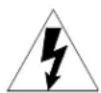
The lightning flash with arrowhead symbol, within an equilateral triangle, is intended to alert the user to the presence of uninsulated “dangerous voltage” within the product’s enclosure that may be of sufficient magnitude to constitute a risk of electric shock to persons.
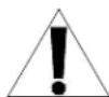
The exclamation point within an equilateral triangle is intended to alert the user to the presence of important operating and maintenance (servicing) instructions in the literature accompanying the appliance.
WARNING:
THIS IS AN APPARATUS WITH CLASS I CONSTRUCTION. IT SHALL BE CONNECTED TO AN ELECTRICAL OUTLET WITH AN EARTHING GROUND TERMINAL.
IMPORTANT:
This device can be used with Class 2 output wiring.
Regulatory Compliance
As of the date of manufacture, the SWE-8 has been tested and found to comply with specifications for CE marking.
CE
Federal Communications Commission (FCC) Compliance Statement
This device complies with part 15 of the FCC Rules. Operation is subject to the following conditions:
(1) This device may not cause harmful interference and (2) this device must accept any interference received, including interference that may cause undesired operation.
CAUTION: Changes or modifications not expressly approved by the manufacturer responsible for compliance could void the user's authority to operate the equipment.
NOTE: This equipment has been tested and found to comply with the limits for a Class B digital device, pursuant to part 15 of the FCC Rules. These limits are designed to provide reasonable protection against harmful interference in a residential installation. This equipment generates, uses and can radiate radio frequency energy and, if not installed and used in accordance with the instructions, may cause harmful interference to radio communications. However, there is no guarantee that interference will not occur in a particular installation. If this equipment does cause harmful interference to radio or television reception, which can be determined by turning the equipment off and on, the user is encouraged to try to correct the interference by one or more of the following measures:
• Reorient or relocate the receiving antenna
- Increase the separation between the equipment and receiver
- Connect the equipment into an outlet on a circuit different from that to which the receiver is connected
- Consult the dealer or an experienced radio/TV technician for help
Industry Canada (IC) Compliance Statement
CAN ICES-3(B)/NMB-3(B)
The specific patents that cover Crestron products are listed at patents.crestron.com.
Crestron, the Crestron logo, Cresnet, Crestron Home, and Sonnex are either trademarks or registered trademarks of Crestron Electronics, Inc. in the United States and/or other countries. Other trademarks, registered trademarks, and trade names may be used in this document to refer to either the entities claiming the marks and names or their products. Crestron disclaims any proprietary interest in the marks and names of others. Crestron is not responsible for errors in typography or photography.
This document was written by the Technical Publications department at Crestron.
©2014 Crestron Electronics, Inc.
Contents
Sonnex Multiroom Audio Unamplified Expander, 8 Zone: SWE-8 1
Introduction ...... 1
Features and Functions....1
Applications....3
Specifications 3
Physical Description....5
Setup 8
Sonnex Link Wiring 8
Installation 8
Hardware Hookup 10
Configuration....12
Uploading and Upgrading....13
Establishing Communication....13
Programs and Firmware 13
Operation 14
Problem Solving 15
Troubleshooting....15
Check Wiring 15
Reference Documents....15
Further Inquiries 15
Future Updates 16
Return and Warranty Policies....17
Merchandise Returns / Repair Service 17
Crestron Limited Warranty....17
Sonnex Multiroom Audio Unamplified Expander, 8 Zone: SWE-8
Introduction
The SWE-8 is an 8-zone unamplified expander for the Sonnex ^® Multiroom Audio System (SWAMP-24X8) ^1 from Crestron ^® . It provides eight zone outputs consisting of four analog line-level and four S/PDIF digital outputs. All eight outputs also include Crestron Home ^® (CH) CAT5 balanced audio outputs for long-distance wiring applications. The SWE-8 is ideal for routing audio to AV receivers, powered subwoofers, headphone amplifiers, phone systems (for music-on-hold), and other audio equipment.
Features and Functions
• Eight zone Sonnex expansion with line-level outputs
• Four zones with balanced and unbalanced line outputs
• Four zones with S/PDIF digital outputs
• All eight zones include Crestron Home CAT5 balanced outputs
• All ports on an output are paralleled ^2
• Professional-quality audio performance
• Advanced DSP, mono summing, and output bussing per zone
• Single-cable interface to SWAMP-24X8 via Sonnex Link
• Plug-and-play operation
• Single-space rack mountable
8 Zones Unamplified
The SWE-8 allows routing of any of the main SWAMP-24X8's 24 source inputs to any of its eight zone outputs. Outputs 1-4 offer balanced, unbalanced, and CH outputs. Outputs 5-8 offer S/PDIF and CH outputs.
- Item sold separately.
- The total load should be greater than 2 kΩ if multiple ports for the same zone are used simultaneously.
Crestron Home CAT5 Audio Distribution
The CH CAT5 balanced outputs enable long-distance wire runs up to 500 feet (152 meters) to feed remote equipment such as powered subwoofers and AV receivers located throughout the house. The CH signal is easily converted to unbalanced line-level at each remote location using an ABAR-1 CAT5 Balanced Audio Receiver. ^1 CH outputs are also compatible with other Crestron Home products such as the C2N-IADS30X24, CNX-BIPAD8, CNXRMCLV, C2N-DAP8, ^1 and certain Crestron touch screens.
AUD-EXT Audio Extenders
For long-distance wiring applications requiring wire runs over 500 feet (152 m), Crestron offers the AUD-EXT family of audio extenders. ^1 Using inexpensive CAT5 wire, these extenders allow unbalanced audio signals to be extended up to 2000 feet (610 m), while SPDIF signal can be extended up to 600 feet (183 m).
Digital Signal Processing
Each zone features independent DSP for optimal sound quality and control in every room. Sonnex DSP capabilities include the choice of graphic or parametric 5-band EQ, dynamic range control, volume, bass, treble, balance, loudness, mute, mono summing, and five selectable tone profiles. For subwoofer applications, a choice of second or fourth order active crossover filters can be set using the parametric EQ, leaving the four remaining EQ filters available for room correction and tonal enhancement.
Output Bussing
Output bussing allows multiple zones to function as one, whether fed from the SWE-8, the SWAMP-24X8, or another Sonnex Expander. Output bussing is ideal for grouping adjacent listening areas together or associating a powered subwoofer with its stereo speaker pair. Volume offset adjustments allow for balancing the levels of each bussed zone for smooth, even coverage.
Simple, Versatile Installation
The SWE-8 can be installed along with the SWAMP-24X8 at the central equipment rack, or separately at a remote location. It interfaces with the SWAMP-24X8 via a single CAT5e shielded twisted pair (STP) cable up to 200 feet (61 meters) in length. ^2 This length can be increased to 2000 feet (610 meters) using multimode fiber optic cable with the S-EXT1-S Sonnex Link over Fiber Extender. ^1 Plug-and-play connectivity affords an extremely easy installation with full control access to all the SWE-8 functions provided through the SWAMP-24X8.
-
Item(s) sold separately.
-
For connection of the Sonnex Link between the SWAMP-24X8 and each expander, use Crestron DM-CBL-8G or high-quality CAT5e shielded twisted-pair cable. The maximum cable length using DM-CBL-8G or CAT5e is 200 ft (61 m) per run. For longer distances, use the S-EXT1-S Sonnex Link over Fiber Extender.
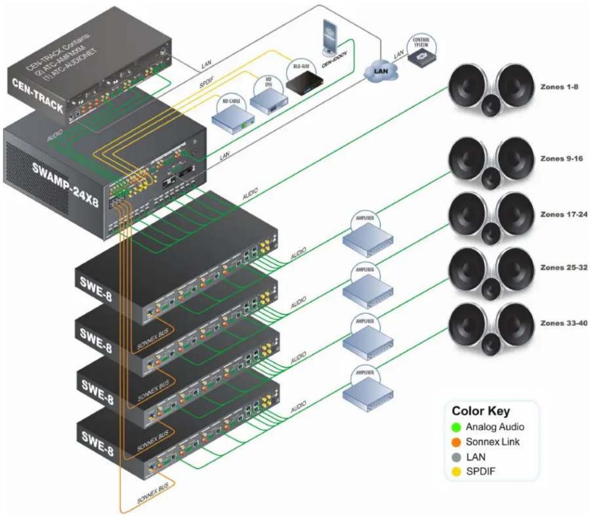
Applications
The following diagram shows a SWE-8 in a multizone application.
SWE-8 in a Multizone Application
flowchart
graph TD
    A["CEN-TRACK"] -->|LAN| B["SWAMP-24X8"]
    C["SWAMP-24X8"] -->|LAN| B
    B --> D["LAN"]
    D --> E["Zones 1-8"]
    B --> F["Zones 9-16"]
    B --> G["Zones 17-24"]
    B --> H["Zones 25-32"]
    B --> I["Zones 33-40"]
    B --> J["SOWEX BUS"]
    B --> K["SOWEX BUS"]
    B --> L["SOWEX BUS"]
    M["CEN-DOCV"] --> N["LAN"]
    O["CONTROL SYSTEM"] --> P["LAN"]
    Q["ANOG Audio"] --> R["AMPUER"]
    S["Sonnex Link"] --> T["AMPUER"]
    U["LAN"] --> V["AMPUER"]
    W["SPDIF"] --> X["HD CABLE"]
    W --> Y["HD DIS"]
    W --> Z["BUU-RUB"]
    style A fill:#f9f,stroke:#333
    style C fill:#f9f,stroke:#333
    style M fill:#ccf,stroke:#333
    style O fill:#ccf,stroke:#333
    style Q fill:#ccf,stroke:#333
    style R fill:#dfd,stroke:#333
    style S fill:#dfd,stroke:#333
    style T fill:#dfd,stroke:#333
    style U fill:#dfd,stroke:#333
    style V fill:#dfd,stroke:#333
    style W fill:#dfd,stroke:#333
Specifications
Specifications for the SWE-8 are listed in the following table.
SWE-8 Specifications
| SPECIFICATION DETAILS | |
| AudioInput Signal TypeOutput Signal Types Stereo analog | Sonnex Linkline (unbalanced and balanced), S/PDIF coaxial (2-channel PCM only), Crestron Home CAT5 Balanced Audio |
| Audio (Continued) | |
| Typical of 8 Stereo Zone Outputs | |
| Digital-to-Analog Conversion | 24-bit 48 kHz |
| Output Resolution/Bitrate (digital outputs only) | 24-bit 48 kHz |
| Frequency Response | 20 Hz to 20 kHz, ±0.5 dB |
| Total Harmonic Distortion (THD) + Noise | < 0.003% S/PDIF in, < 0.005% balanced or unbalanced analog in, 20 Hz to 20 kHz |
| S/N Ratio | >106 dB S/PDIF in, >100 dB balanced or unbalanced analog in, A-weighted |
| Stereo Separation | >100 dB |
| Zone Separation | >100 dB |
| Zone Volume Level Control | -80.0 to +20.0 dB, adjustable from 0% to 100% plus mute |
| Bass Control ±12.0 dB | |
| Treble Control ±12.0 dB | |
| Loudness Compensation | On/Off |
| Dynamic Range Control | On/Off |
| Balance Control | Left/right adjustable |
| Mono Summing | Selectable |
| Tone Profiles | Flat, Classical, Jazz, Pop, Rock, Spoken Word |
| EQ Modes | 5-band graphic or 5-band parametric EQ |
| GEQ Center Frequencies | 63, 250, 1k, 4k, 16k Hz |
| GEQ Gain | ±12.0 dB per band |
| PEQ Filter Types | EQ, High Pass, Low Pass, Treble Shelf, Bass Shelf, Notch |
| PEQ Center Frequency | 10 to 20,000 Hz per band |
| PEQ Gain | ±12.0 dB per band |
| PEQ Bandwidth | 0.1 to 3.5 octaves per band |
| Bus Volume Offset | ±12.0 dB per zone for output bussing |
| Communications | |
| Sonnex Link | 64-channel (48 utilized) digital audio with embedded control, auto-discovery, auto-negotiating |
| Power Requirements | |
| Power Pack | 2 amps @ 24 volts dc |
| 100-240 volts ac, 50/60 Hz; power pack included | |
| Environmental | |
| Temperature | 41° to 104°F (5° to 40°C) |
| Humidity | 10% to 90% RH (non-condensing) |
| Heat Dissipation | 41 Btu/h |
| Enclosure | |
| Chassis | Metal with black finish, vented sides |
| Front Panel | Metal with black finish and polycarbonate label overlay |
| Mounting | Freestanding or 1U 19-inch rack-mountable (feet and rack ears included) |
| Dimensions | |
| Height | 1.72 in (44 mm) without feet |
| Width | 19.00 in (483 mm) with ears17.30 in (440 mm) without ears |
| Depth 10.19 in (259 mm) | |
| Weight | 5.0 lbs (2.3 kg) |
| Included Accessory | 24 volt dc, 2 amp regulated universal power pack |
| Available Accessories | |
| ABAR(I)-1 | Crestron Home CAT5 Balanced Audio Receiver |
| AUD-EXT | Audio Extenders |
| CBL Series | Crestron Certified Interface Cables |
| DM-8G-CONN | Cable Connector for DM-CBL-8G |
| DM-8G-CONN-WG | Cable Connector with Wire Guide for DM-CBL-8G |
| DM-8G-CRIMP | Crimping Tool for DM-8G-CONN |
| DM-8G-CRIMP-WG | Crimping Tool for DM-8G-CONN-WG |
| DM-CBL-8G | High Performance CAT5e Shielded Twisted Pair Cable |
| S-EXT1-S | Sonnex Link Over Fiber Extender |
| SWAMP(I)-24X8 | Sonnex Multiroom Audio System |
Physical Description
This section provides information on the connections, controls, and indicators available on the SWE-8.
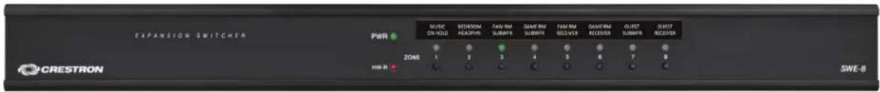
SWE-8 Physical View (Front)
SWE-8 Physical View (Rear)

SWE-8 Overall Dimensions
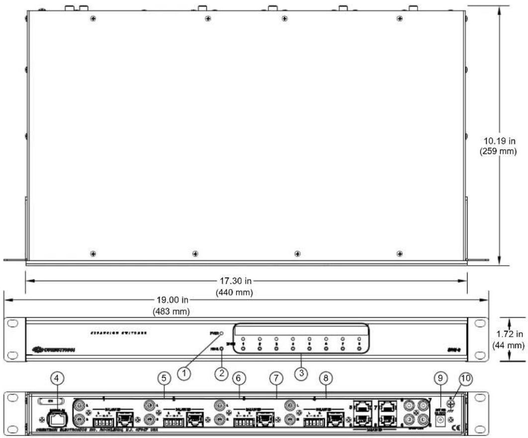
Connectors, Controls, and Indicators
| # CONNECTORS,1CONTROLS, AND INDICATORS | DESCRIPTION | |||
| 1 | PWR LED | (1) Green LED indicates operating power supplied via power pack | ||
| 2 | HW-R | (1) Recessed push button for hardware reset | ||
3 ZONE (1–8)(Buttons and LEDs) | (8) Push buttons and green LEDs, select output zone for routing and adjustment | |||
4 DIGITAL INGreen YellowLED 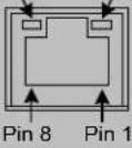 | (1) 8-wire RJ-45 female (8P8C modular jack); Sonnex link input; Connect to SWAMP-24X8 Multiroom Audio System ^2 or S-EXT1-S Sonnex Link Over Fiber Extender ^2 (each sold separately); Green LED indicates link status; Amber LED indicates data communication | |||
5 1-4 L/R (unbalanced)  | (4) Pairs RCA female;Unbalanced stereo line-level audio outputs3Output impedance: 100 ΩMaximum output level: 2 Vrms | |||
6 1-4 BALANCED L/R | (4) 5-pin 3.5 mm detachable terminal blocks;Balanced stereo line-level audio outputs3Output impedance: 200 Ω balanced,100 Ω unbalanced;Maximum output level: 4 Vrms balanced,2 Vrms unbalanced | |||
7 1-8 BALANCED (CH) | (8) 8-wire RJ-45 female, shielded “Crestron Home” CAT5 balanced stereo audio output ports. Connect to any “CH” CAT5 audio input ports or bidirectional audio ports3,4Maximum cable length: 500 feet(152 meters) per port | |||
| PIN | WIRE COLORS(568B) | AUDIO I/O | ||
| 1 | WHITE/ORANGE | + Left Out | ||
| 2 ORANGE - Left Out | ||||
| 3 WHITE/GREEN + Right Out | ||||
| 4 BLUE N/A | ||||
| 5 WHITE/BLUE N/A | ||||
| 6 | GREEN | - Right Out | ||
| 7 | WHITE/BROWN | N/A | ||
| 8 | BROWN | N/A | ||
| 8 | 5-8 SPDIF OUT | (4) RCA female; S/PDIF coaxial digital audio outputsOutput impedance: 75 Ω | ||
| 9 | 24 VDC 2.0A | (1) 2.1 mm barrel dc power jack;24 volt dc power input(power pack included) | ||
| 10 | GROUND[×262] | (1) 6-32 screw, chassis ground lug | ||
(Continued on following page)
-
Interface connectors for BALANCED L/R ports are provided with the unit.
-
For connection of the Sonnex Link between the SWE-8 and the SWAMP-24X8 or S-EXT1-S, use Crestron DM-CBL-8G or high-quality CAT5e shielded twisted-pair cable. The maximum cable length is 200 ft (61 meters) per run. For longer distances, use the S-EXT1-S.
-
All analog outputs are paralleled per zone.
-
This eight-pin RJ-45 port uses CAT5 wiring to provide connectivity to the ABAR-1 CAT5 Balanced Audio Receiver and other Crestron Home products such as the C2N-IADS30X24, CNX-BIPAD8, CNXRMCLV, C2N-DAP8, and certain Crestron touch screens.
Setup
Sonnex Link Wiring
Crestron recommends using Crestron DM-CBL-8G (sold separately) or high-quality CAT5e shielded twisted-pair cable for Sonnex Link connections between the SWE-8 and the SWAMP-24X8 or S-EXT1-S.
NOTE: Shielded connectors such as the DM-8G-CONN (sold separately) must be used.
DM-CBL-8G wire can carry Sonnex Link signals up to 200 feet (61 meters). If additional length is needed, the S-EXT1-S can extend the Sonnex link up to 2000 feet (610 meters) over one multimode fiber strand. The S-EXT1-S is an optional accessory that provides high performance signal extension.
Installation
Ventilation
The SWE-8 should be used in a well-ventilated area. The venting holes should not be obstructed under any circumstances.
To prevent overheating, do not operate this product in an area that exceeds the environmental temperature range listed in the table of specifications. Consider using forced air ventilation or incrementing the spacing between units to reduce overheating. Contact with thermal insulating materials should be avoided on all sides of the unit.
Rack Mounting
The SWE-8 can be mounted in a rack or stacked with other equipment. Two “ears” are provided with the SWE-8 so that the unit can be rack mounted. These ears must be installed prior to mounting. Complete the following procedure to attach the ears to the unit. The only tool required is a #1 or #2 Phillips screwdriver.
WARNING: To prevent bodily injury when mounting or servicing this unit in a rack, observe the following guidelines:
- When mounting this unit in a partially filled rack, load the rack from the bottom to the top with the heaviest component at the bottom of the rack.
- If the rack is provided with stabilizing devices, install the stabilizers before mounting or servicing the unit in the rack.
NOTE: Observe the following guidelines when installing equipment in a rack:
- Elevated Operating Ambient Temperature - If installed in a closed or multi-unit rack assembly, the operating ambient temperature of the rack environment may be greater than room ambient temperature. Therefore, consideration should be given to installing the equipment in an environment compatible with the maximum ambient temperature (Tma) specified by the manufacturer.
-
Reduced Air Flow - Installation of the equipment in a rack should be such that the amount of airflow required for safe operation of the equipment is not compromised.
-
Mechanical Loading - Mounting of the equipment in the rack should be such that a hazardous condition is not achieved due to uneven mechanical loading.
- Circuit Overloading - Consideration should be given to the connection of the equipment to the supply circuit and the effect that overloading of the circuits might have on overcurrent protection and supply wiring. Appropriate consideration of equipment nameplate ratings should be used when addressing this concern.
- Reliable Earthing - Reliable earthing of rack-mounted equipment should be maintained. Particular attention should be given to supply connections other than direct connections to the branch circuit (e.g., use of power strips)
NOTE: If rack mounting is not required, rubber feet are provided for tabletop mounting or stacking. Apply the feet near the corner edges on the underside of the unit.
To install the ears, use the following procedure.
CAUTION: To prevent equipment damage, use only the rack ears Crestron provides for this device.
- Using a #1 or #2 Phillips screwdriver, remove the three screws closest to the front panel from one side of the unit. Refer to the diagram following step 3 for a detailed view.
- Position a rack ear so that its mounting holes align with the holes vacated by the screws in step 2.
- Secure the car to the unit with the three screws from step 2 as shown in the following diagram.

- Repeat procedure (steps 1 through 3) to attach the remaining ear to the opposite side.
Four “feet” are provided with the SWE-8 so that if the unit is not rack mounted, the rubber feet can provide stability when the unit is placed on a flat surface or stacked. These feet should be attached prior to the hookup procedure.
NOTE: No more than two SWE-8 units should be stacked.
Stacking
Hardware Hookup
Connect the Device
Make the necessary connections as called out in the illustration that follows this paragraph. Refer to “Sonnex Link Wiring” on page 8 for additional information. Apply power after all connections have been made.
When making connections to the SWE-8, use a Crestron power supply for Crestron equipment.
Hardware Connections for the SWE-8

CAUTION: Keep the device unplugged until the output wiring is complete.
NOTE: Ensure the unit is properly grounded by connecting the chassis ground lug to an earth ground (building steel).
NOTE: To prevent overheating, do not operate this product in an area that exceeds the environmental temperature range listed in the table of specifications.
Four balanced/unbalanced audio outputs are provided, utilizing 5-pin terminal block connectors. For connection details, refer to the following table and diagrams.
Audio Connections
| SIGNAL NAME | BALANCED AUDIO OUTPUT | UNBALANCED AUDIO OUTPUT |
| + L + L + Out | ||
| - L - Open | ||
| G | Shield/ground | Common ground |
| + R + R + Out | ||
| - | R - | Open |
Typical Balanced/Unbalanced Outputs
Balanced Output

Unbalanced Output

Connect to SWAMP24X8 or S-EXT1-S Sonnex Link Over Fiber Extender
The SWE-8 can be connected to a SWAMP-24X8 or S-EXT1-S Sonnex Link Over Fiber Extender via shielded CAT5 cable.
SWAMP-24X8 to SWE-8 Connection
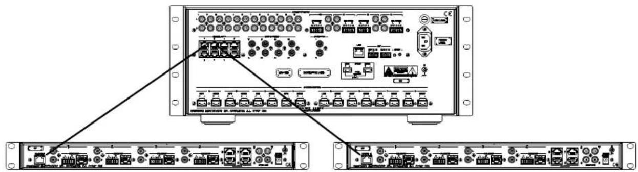
NOTE: When the SWAMP-24X8 is connected to a control system using Cresnet ^® , only one SWE-8 can be connected.
NOTE: When connecting a SWAMP-24X8 or S-EXT1-S to a SWE-8, Crestron recommends using Crestron DM-CBL-8G or high-quality CAT5c shielded twisted-pair cable. Shielded connectors such as the DM-8G-CONN (sold separately) must be used.
NOTE: The maximum cable length between a SWAMP-24X8 or S-EXT1-S and SWE-8 is 200 feet (61 meters).
Label the Buttons
Use Crestron Engraver software to print custom labels for the SWE-8's front panel buttons and LEDs. Crestron recommends printing on 100-pound paper. Paper weighing less than 100 pounds tends to crumple while sliding in, while paper weighing more than 100 pounds may not fit.
Configuration
The SWE-8 is automatically configured from the front panel of a connected SWAMP-24X8 or by Sonnex Tools software. For more information on configuration options, refer to the SWAMP(1)-24X8 Sonnex Multiroom Audio System Operations Guide (Doc. 7049) at www.crestron.com/manuals.
Uploading and Upgrading
Crestron recommends using the latest programming software and that each device contains the latest firmware to take advantage of the most recently released features. However, before attempting to upload or upgrade it is necessary to establish communication.
Establishing Communication
All communications with the SWE-8 are managed through the communication link with a connected SWAMP-24X8. For information, refer to the SWAMP(I)-24X8 Sonnex Multiroom Audio System Operations Guide (Doc. 7049) at www.crestron.com/manuals.
Programs and Firmware
Any program or firmware updates are managed by the connection with the SWAMP-24X8. For information, refer to the SWAMP(I)-24X8 Sonnex Multiroom Audio System Operations Guide (Doc. 7049) at www.crestron.com/manuals
Operation
The SWE-8 operates in either Zone mode or Source mode. The SWE-8's operating mode is determined by the operating mode of the SWAMP-24X8.
For information on operating the SWAMP-24X8, refer to the SWAMP(I)-24X8 Sonnex Multiroom Audio System Operations Guide (Doc. 7049) at www.crestron.com/manuals.
Zone Mode
Zone mode uses the SWAMP-24X8's front panel to route a source signal to a selected zone. To use Zone mode, perform the following procedure:
- Place the SWAMP-24X8 in Zone mode.
- Press the ZONE button of the zone to be controlled.
- Press the SOURCE button of the source to be routed. The associated SOURCE and ZONE LEDs light. Alternatively, press the ZONE button twice to turn on the zone and connect the last-selected source.
- To turn off the zone, press the ZONE button.
Source Mode
Source mode uses the SWAMP-24X8's front panel to select a source signal and route it to multiple zones. To use Source mode, perform the following procedure:
- Place the SWAMP-24X8 in Source mode.
- On the SWAMP-24X8, press the SOURCE button of the source to be routed. The associated SOURCE LED lights.
- On the SWE-8, press the ZONE buttons of the zones to be selected. The associated ZONE LED(s) lights.
- To remove a zone from a source, press the desired ZONE button. The associated ZONE LED turns off.
Problem Solving
Troubleshooting
The following table provides corrective action for possible trouble situations. If further assistance is required, please contact a Crestron customer service representative.
SWE-8 Troubleshooting
| TROUBLE POSSIBLE CAUSE(S) CORRECTIVE | ||
| ACTION | ||
| Audio dropouts are heard on an SWE-8 zone. | There is a bad shield or no shield on the Sonnex cable connecting the SWAMP-24X8 and the peripheral device. | Ensure continuity and integrity of the shield on both ends of the Sonnex cable. |
| Device loses functionality due to electrostatic discharge. | The device is improperly grounded. | Check that all ground connections have been made properly. |
| An incorrect audio signal is heard. | The signal is incorrectly routed. | Reroute the signal. |
| The zone is incorrectly bussed with other zones. | Remove the zone from the bus. | |
Check Wiring
To ensure optimum performance over the full range of the installation topology, use
Crestron Certified Wire only. Failure to do so may incur additional charges if support is required to identify performance deficiencies because of using improper wire.
Reference Documents
All documents mentioned in this guide are available at www.crestron.com/manuals.
List of Related Reference Documents
| DOCUMENT TITLE |
| SWAMP(I)-24X8 Sonnex Multiroom Audio System |
Further Inquiries
To locate specific information or resolve questions after reviewing this guide, contact Crestron's True Blue Support at 1-888-CRESTRON [1-888-273-7876] or, for assistance within a particular geographic region, refer to the listing of Crestron worldwide offices at www.crestron.com/offices.
To post a question about Crestron products, log onto Crestron's Online Help at www.crestron.com/onlinehelp. First-time users must establish a user account to fully benefit from all available features.
Future Updates
As Crestron improves functions, adds new features, and extends the capabilities of the SWE-8, additional information may be made available as manual updates. These updates are solely electronic and serve as intermediary supplements prior to the release of a complete technical documentation revision.
Check the Crestron website periodically for manual update availability and its relevance. Updates are identified as an “Addendum” in the Download column.
Return and Warranty Policies
Merchandise Returns / Repair Service
- No merchandise may be returned for credit, exchange or service without prior authorization from Crestron. To obtain warranty service for Crestron products, contact an authorized Crestron dealer. Only authorized Crestron dealers may contact the factory and request an RMA (Return Merchandise Authorization) number. Enclose a note specifying the nature of the problem, name and phone number of contact person, RMA number and return address.
- Products may be returned for credit, exchange or service with a Crestron Return Merchandise Authorization (RMA) number. Authorized returns must be shipped freight prepaid to Crestron, 6 Volvo Drive, Rockleigh, N.J. or its authorized subsidiaries, with RMA number clearly marked on the outside of all cartons. Shipments arriving freight collect or without an RMA number shall be subject to refusal. Crestron reserves the right in its sole and absolute discretion to charge a 15% restocking fee plus shipping costs on any products returned with an RMA.
- Return freight charges following repair of items under warranty shall be paid by Crestron, shipping by standard ground carrier. In the event repairs are found to be non-warranty, return freight costs shall be paid by the purchaser.
Crestron Limited Warranty
Crestron Electronics, Inc. warrants its products to be free from manufacturing defects in materials and workmanship under normal use for a period of three (3) years from the date of purchase from Crestron, with the following exceptions: disk drives and any other moving or rotating mechanical parts, pan/tilt heads and power supplies are covered for a period of one (1) year; touch screen display and overlay components are covered for 90 days; batteries and incandescent lamps are not covered.
This warranty extends to products purchased directly from Crestron or an authorized Crestron dealer. Purchasers should inquire of the dealer regarding the nature and extent of the dealer's warranty, if any.
Crestron shall not be liable to honor the terms of this warranty if the product has been used in any application other than that for which it was intended or if it has been subjected to misuse, accidental damage, modification or improper installation procedures. Furthermore, this warranty does not cover any product that has had the serial number altered, defaced or removed.
This warranty shall be the sole and exclusive remedy to the original purchaser. In no event shall Crestron be liable for incidental or consequential damages of any kind (property or economic damages inclusive) arising from the sale or use of this equipment. Crestron is not liable for any claim made by a third party or made by the purchaser for a third party.
Crestron shall, at its option, repair or replace any product found defective, without charge for parts or labor. Repaired or replaced equipment and parts supplied under this warranty shall be covered only by the unexpired portion of the warranty.
Except as expressly set forth in this warranty, Crestron makes no other warranties, expressed or implied, nor authorizes any other party to offer any warranty, including any implied warranties of merchantability or fitness for a particular purpose. Any implied warranties that may be imposed by law are limited to the terms of this limited warranty. This warranty statement supersedes all previous warranties.

CRESTRON®
Crestron Electronics, Inc.
15 Volvo Drive Rockleigh, NJ 07647 (2033120)
Tel: 888.CRESTRON 03.14
Fax: 201.767.7576
www.crestron.com

Operations Guide - DOC. 7202B
Specifications subject to
change without notice.
- Important Safety Instructions
- WARNING:
- IMPORTANT:
- Regulatory Compliance
- CE
- Federal Communications Commission (FCC) Compliance Statement
- Contents
- Sonnex Multiroom Audio Unamplified Expander, 8 Zone: SWE-8 1
- Sonnex Multiroom Audio Unamplified Expander, 8 Zone: SWE-8
- Introduction
- Features and Functions
- Zones Unamplified
- Crestron Home CAT5 Audio Distribution
- AUD-EXT Audio Extenders
- Digital Signal Processing
- Output Bussing
- Simple, Versatile Installation
- Applications
- Specifications
- Physical Description
- Setup
- Sonnex Link Wiring
- Installation
- Ventilation
- Rack Mounting
- Hardware Hookup
- Connect the Device
- Typical Balanced/Unbalanced Outputs
- Configuration
- Uploading and Upgrading
- Establishing Communication
- Programs and Firmware
- Operation
- Zone Mode
- Source Mode
- Problem Solving
- Troubleshooting
- Check Wiring
- Reference Documents
- Further Inquiries
- Future Updates
- Return and Warranty Policies
- Merchandise Returns / Repair Service
- Crestron Limited Warranty
- CRESTRON®
Brand : Crestron
Model : SWE-8
Category : Audio Equipment