
PD7170 - Video projector Planar - Free user manual and instructions
Find the device manual for free PD7170 Planar in PDF.


| Type | Video Projector |
| Brand | Planar |
| Model | PD7170 |
| Display Technology | 3-chip DLP (Texas Instruments) |
| Native Resolution | 1280 x 720 (921,600 pixels) |
| Brightness | 2000 ANSI lumens (average, calibrated at D65) |
| Contrast Ratio | 20,000:1 typical (DynamicBlack On) |
| Standard Lens | Z100, throw ratio 1.82:1 – 2.28:1, motorized zoom/focus/shift |
| Lens Shift | Vertical: up to 65% of screen height; Horizontal: up to 30% of screen width |
| Lamp | 230/260W HPM, user-replaceable, 2500 hours (230W mode) |
| Inputs | 2x HDMI 1.3 (HDCP), 1x Component (RCA), 1x Component (BNC), 1x RGB (HD15), 1x S-Video, 1x Composite, RS-232, IR input, 12V trigger |
| Dimensions (L x W x H) | 25.3 x 20.4 x 8.9 in (643 x 519 x 225 mm) |
| Weight (without lens) | 40.8 lbs (18.5 kg) |
| Power Supply | 100-240V AC, 50-60Hz, 400W max |
| Operating Temperature | 50°F to 95°F (10°C to 35°C) |
| Warranty | 2 years parts and labor (excluding lamp); lamp: 6 months or 1000 hours |
| Video Processing | Gennum GF9450 with 10-bit dual-channel processing, 3:2 pull-down, MPEG artifact reduction |
| Special Features | DynamicBlack, Picture-in-Picture (PIP), ISF calibration, motorized lens controls |
Frequently Asked Questions - PD7170 Planar
User questions about PD7170 Planar
0 question about this device. Answer the ones you know or ask your own.
Ask a new question about this device
Download the instructions for your Video projector in PDF format for free! Find your manual PD7170 - Planar and take your electronic device back in hand. On this page are published all the documents necessary for the use of your device. PD7170 by Planar.
USER MANUAL PD7170 Planar
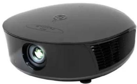
PD7170 Home Theater Projector
natural_image
Black projector with green lens and ventilation grille (no visible text or symbols)Installation & Operation Manual www.planarhometheater.com
TWO YEAR LIMITED WARRANTY
For Projectors, Video Processors and Controllers
Congratulations on your purchase of a Planar video product and welcome to the Planar family! With proper installation, setup and care, you should enjoy many years of unparalleled video performance.
This is a LIMITED WARRANTY as defined in the Magnuson-Moss Warranty Act. Please read it carefully and retain it with your other important documents.
WHAT IS COVERED UNDER THE TERMS OF THIS LIMITED WARRANTY:
SERVICE LABOR: Planar will pay for service labor by a Planar Authorized Service Center when needed as a result of manufacturing defect for a period of two (2) years from the effective date of delivery to the end user (excluding the lamp).
PARTS (not including the lamp): Planar will provide new or rebuilt replacement parts for the parts that fail due to defects in materials or workmanship for a period of two (2) years from the effective date of delivery to the end user. Such replacement parts are then subsequently warranted for the remaining portion (if any) of the original warranty period.
PROJECTOR LAMP: Planar will pay for service labor by a Planar Authorized Service Center when needed as a result of a manufacturing defect for a period of six (6) months or 1000 hours, whichever comes first, from the effective date of delivery to the end user. In addition, Planar will provide a new or rebuilt replacement lamp for the lamp that fails due to defects in materials or workmanship for a period of six (6) months or 1000 hours, whichever comes first, from the effective date of delivery to the end user. Such replacement lamps are then subsequently warranted for the remaining portion (if any) of the original warranty period.
WHAT IS NOT COVERED UNDER THE TERMS OF THIS LIMITED WARRANTY:
This Limited Warranty only covers failure due to defects in materials and workmanship that occur during normal use and does not cover normal maintenance. This Limited Warranty does not cover cabinets or any appearance items; failure resulting from accident, misuse, abuse, neglect, mishandling, misapplication, faulty or improper installation or setup adjustments; improper maintenance, alteration, improper use of any input signal; damage due to lightning or power line surges, spikes and brownouts; damage that occurs during shipping or transit; or damage that is attributed to acts of God. In the case of remote control units, damage resulting from leaking, old, damaged or improper batteries is also excluded from coverage under this Limited Warranty.
CAUTION: THIS LIMITED WARRANTY ONLY COVERS PLANAR PRODUCTS PURCHASED FROM PLANAR AUTHORIZED DEALERS. ALL OTHER PRODUCTS ARE SPECIFICALLY EXCLUDED FROM COVERAGE UNDER THIS WARRANTY. MOREOVER, DAMAGE RESULTING DIRECTLY OR INDIRECTLY FROM IMPROPER INSTALLATION OR SETUP IS SPECIFICALLY EXCLUDED FROM COVERAGE UNDER THIS LIMITED WARRANTY. IT IS IMPERATIVE THAT INSTALLATION AND SETUP WORK BE PERFORMED ONLY BY AN AUTHORIZED PLANAR DEALER TO PROTECT YOUR RIGHTS UNDER THIS WARRANTY. THIS WILL ALSO ENSURE THAT YOU ENJOY THE FINE PERFORMANCE OF WHICH YOUR PLANAR PRODUCT IS CAPABLE WHEN INSTALLED AND CALIBRATED BY PLANAR AUTHORIZED PERSONNEL.
RIGHTS, LIMITS AND EXCLUSIONS:
Planar limits its obligations under any implied warranties under state laws to a period not to exceed the warranty period. There are no express warranties. Planar also excludes any obligation on its part for incidental or consequential damages related to the failure of this product to function properly. Some states do not allow limitations on how long an implied warranty lasts, and some states do not allow the exclusion or limitation of incidental or consequential damages. So the above limitations or exclusions may not apply to you. This warranty gives you specific legal rights, and you may also have other rights that vary from state to state.
EFFECTIVE WARRANTY DATE:
This warranty begins on the effective date of delivery to the end user. For your convenience, keep the original bill of sale as evidence of the purchase date.
IMPORTANT – WARRANTY REGISTRATION:

Please fill out and mail your warranty registration card. It is imperative that Planar knows how to reach you promptly if we should discover a safety problem or product update for which you must be notified.
CONTACT A PLANAR AUTHORIZED SERVICE CENTER TO OBTAIN SERVICE:
Repairs made under the terms of this Limited Warranty covering your Planar video product will be performed at the location of the product, during usual working hours, providing location of product is within normal operating distance from a Planar Authorized Service Center. In some instances it may be necessary for the product to be returned to the Planar factory for repairs. If, solely in Planar's judgment, location of product to be repaired is beyond normal operating distance of the closest Planar Authorized Service Center, or the repair requires the unit be returned to the Planar factory, it is the owner's responsibility to arrange for shipment of the product for repair. These arrangements must be made through the selling Planar Dealer. If this is not possible, contact Planar directly for a Return Authorization number and shipping instructions. Planar will return product transportation prepaid in the United States, unless no product defect is discovered. In that instance, shipping costs will be the responsibility of the owner.
COPYRIGHT AND TRADEMARKS:
© Copyright 2008 Planar Systems, Inc. This document contains proprietary information protected by copyright, trademark and other intellectual property laws. All rights are reserved. No part of this manual may be reproduced by any mechanical, electronic or other means, in any form, without prior written permission of the manufacturer.
Trademarks and registered trademarks used in this document are the property of their respective owners.
ADDITIONAL INFORMATION:
To locate the name and address of the nearest Planar Authorized Service Center, or for additional information about this Limited Warranty, please call or write:
Planar Systems, Inc.
1195 NW Compton Drive
Beaverton, OR 97006-1992
Ph: (503) 748-5799
Fax: (503) 682-9441
Toll Free: (866) PLANAR1
PLANAR VIDEO PRODUCT INFORMATION RETAIN THIS INFORMATION FOR YOUR RECORDS
Model Purchased Date
Serial Number
Planar Authorized Dealer Name
Address
City
State/Province
Postal Code
Phone Fax
Important Safety Instructions
Thank you for your purchase of this quality Planar product! For best performance, please read this manual carefully as it is your guide through the menus and operation.

WARNING
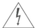
This symbol is intended to alert the user to the presence of uninsulated "dangerous voltage" within the product's enclosure that may be of sufficient magnitude to constitute a risk of electric shock.
This symbol is intended to alert the user to the presence of important operating and maintenance (servicing) instructions in the literature accompanying the appliance.
- Read these instructions.
- Keep these instructions.
- Heed all warnings.
- Follow all instructions.
- Do not use this apparatus near water.
-
Clean only with a dry cloth.
-
Do not block any of the ventilation openings. Install in accordance with the manufacturer's instructions.
-
Do not install near any heat sources such as radiators, heat registers, stoves, or other apparatus (including amplifiers) that produce heat.
-
Do not defeat the safety purpose of the polarized or grounding type plug. A polarized plug has two blades with one wider than the other. A grounding type plug has two blades and a third grounding prong. The wide blade or the third prong is provided for your safety. When the provided plug does not fit into your outlet, consult an electrician for the replacement of the obsolete outlet.
-
Protect the power cord from being walked on or pinched particularly at plugs, convenience receptacles and the point where they exit from the apparatus.
-
Only use the attachments/accessories specified by Planar Systems.
-
Use only with a cart, stand, tripod, bracket or table specified by the manufacturer or sold with the apparatus. When a cart is used, use caution when moving the cart/apparatus to avoid injury from tip-over.

-
Unplug this apparatus during lightning storms or when unused for long periods of time.
-
Refer all servicing to qualified service personnel. Servicing is required when the apparatus has been damaged in any way, such as power supply cord or plug is damaged, liquid has been spilled or objects have fallen into the apparatus, the apparatus has been exposed to rain or moisture, does not operate normally, or has been dropped.
-
The +12V trigger only outputs 12Vdc signal for triggering. Do not connect to any other power input or output. This could cause damage to this unit.
-
Keep the packing material in case the equipment should ever need to be shipped.
-
The lamp becomes extremely hot during operation. Allow the projector to cool down for approximately 45 minutes prior to removing the lamp assembly for replacement.
-
Do not operate lamps beyond the rated lamp life. Excessive operation of lamps beyond rated life could cause them to explode in rare occasions.
- Never look directly into the lens when the lamp is on.
Compliance Information
DECLARATION OF CONFORMITY:
Manufacturer's Name: Planar Systems, Inc.
Manufacturer's Address: 1195 NW Compton Drive, Beaverton, OR 97006
hereby declares that the products Model Numbers:
PD7170
conform with the provisions of:
Council Directive 2004/108/EC on Electromagnetic Compatibility;
EN 55022 "Limits and methods of measurements of radio interference characteristics of information technology equipment" 1998;
EN 55024 "Limits and methods of measurements of immunity characteristics of information technology equipment" 1998;
Including:
- EN 61000-4-2 "Electromagnetic compatibility (EMC) Part 4: Testing and measurement techniques Section 2: Electrostatic discharge immunity test"
- EN 61000-4-3 "Electromagnetic compatibility (EMC) Part 4: Testing and measurement techniques Section 3: Radiated, Radio-Frequency, Electromagnetic Field Immunity Test"
- EN 61000-4-4 "Electromagnetic compatibility (EMC) Part 4: Testing and measurement techniques Section 4: Electrical fast transient/burst immunity test"
- EN 61000-4-5 "Electromagnetic compatibility (EMC) Part 4: Testing and measurement techniques Section 5: Surge immunity test"
- EN 61000-4-6 "Electromagnetic compatibility (EMC) Part 4: Testing and measurement techniques Section 6: Conducted disturbances induced by radio-frequency fields immunity test"
- EN 61000-4-8 "Electromagnetic compatibility (EMC) Part 4: Testing and measurement techniques Section 8: Conducted disturbances induced by power frequency magnetic fields immunity test"
- EN 61000-4-11 "Electromagnetic compatibility (EMC) Part 4: Testing and measurement techniques Section 11: Voltage dips, short interruptions and voltage variations immunity tests"
And:
- EN 61000-3-2 "Electromagnetic compatibility (EMC) Part 3, Section 2: Limits for harmonic current emissions (equipment input current up to and including 16 A per phase)" 2000;
- EN 61000-3-3 "Electromagnetic compatibility (EMC) Part 3, Section 3: Limitations of voltage changes, voltage fluctuations and flicker in public low-voltage supply systems, for equipment with rated current up to and including 16 A and not subject to conditional connection" 1995;
Council Directive 2006/95/EC and amended by M1 and C1 on Low Voltage Equipment Safety;
EN 60950 "Safety of information technology equipment, including electrical business equipment"
The Technical Construction file required by this Directive is maintained at the corporate headquarters of Planar Systems, Inc., 1195 NW Compton Drive, Beaverton, OR 97006.
Date of Declaration: February 2008
FCC PART 15:
NOTE: This equipment has been tested and found to comply with the limits for a Class B digital device, pursuant to Part 15 of the FCC Rules. These limits are designed to provide reasonable protection against harmful interference in a residential installation.
This equipment generates, uses and can radiate radio frequency energy and, if not installed and used in accordance with the instructions, may cause harmful interference to radio communications. However, there is no guarantee that interference will not occur in a particular installation. If this equipment does cause harmful interference to radio or television reception, which can be determined by turning the equipment off and on, the user is encouraged to try to correct the interference by one or more of the following measures:
- Reorient or relocate the receiving antenna.
- Increase the separation between the equipment and receiver.
- Connect the equipment into an outlet on a circuit different from that to which the receiver is connected.
- Consult the dealer or an experienced radio/TV technician for help.
INDUSTRY CANADA (ICES-003):

This Class B digital apparatus complies with Canadian ICES-003.
IMPORTANT RECYCLE INSTRUCTIONS

Lamp(s) inside this product contain mercury. This product may contain other electronic waste that can be hazardous if not disposed of properly. Recycle or dispose in accordance with local, state, or federal Laws.
For more information, contact the Electronic Industries Alliance at WWW.EIAE.ORG.
For lamp specific disposal information check WWW.LAMPRECYCLE.ORG.
DISPOSAL OF OLD ELECTRICAL AND ELECTRONIC EQUIPMENT (Applicable throughout the European Union and other European countries with separate collection programs)

This symbol found on your product or on its packaging, indicates that this product should not be treated as household waste when you wish to dispose of it. Instead, it should be handed over to an applicable collection point for the recycling of electrical and electronic equipment. By ensuring this product is disposed of correctly, you will help prevent potential negative consequences to the environment and human health, which could otherwise be caused by inappropriate disposal of this product. The recycling of materials will help to conserve natural resources. This symbol is only valid in the European Union. If you wish to discard this product, please contact your local authorities or dealer and ask for the correct method of disposal.
Table of Contents
TWO YEAR LIMITED WARRANTY ....iii
Important Safety Instructions ...... vi
Compliance Information ......vii
1. Introduction ...... 1
About This Manual ....1
Target Audience ....1
If You Have Comments About This Manual....1
Textual and Graphic Conventions....1
Using This Manual 2
Description, Features and Benefits ....3
Key Features and Benefits....3
Parts List 4
2. Controls and Functions .... 5
PD7170 at a Glance ....5
PD7170 Rear Panel 8
PD7170 Remote Control 9
3. Installation 13
Remote Control 13
Notes on Batteries 13
Notes on Remote Control Operation....13
Quick Setup 15
Installation Considerations ....16
Installation Type....16
Ambient Light 17
Throw Distance....17
Vertical and Horizontal Position....18
Vertical and Horizontal Lens Shift 19
Folded Optics 20
Other Considerations....20
Lens Replacement 21
Mounting the PD7170 23
Floor Mounting (Upright) 23
Ceiling Mounting (Inverted)....23
Adjusting the Projection Angle....23
Connections to the PD7170 23
Connector Panel Access 24
Connecting Source Components to the PD7170 25
RS-232 Controller Connection ....29
Connecting 12-Volt Trigger Output to External Theater Equipment .....30
Connecting an External IR Receiver....30
Connecting to AC Power 31
Turning on the Power ....31
Lens Adjustments ....31
Focus 31
Zoom....31
Lens Shift....31
Changing the OSD Language 32
Adjusting the Picture Orientation ....33
Rear Projection....33
Ceiling Mode 33
- Operation 35
Selecting Video Memory ....35
Selecting an Aspect Ratio ....35
Selecting An Input Source ....35
Using Picture-In-Picture (PIP) 36
Using the On-Screen Menus ....37
Main....39
Advanced....49
System 55
Control....59
Language 61
Service....62
- Maintenance and Troubleshooting 65
Lamp Replacement ....65
Troubleshooting Tips 66
6. Serial Communications 69
RS-232 Connection and Port Configuration 69
Serial Command Syntax 69
Key Commands 69
Operations Commands 72
7. Specifications 79
PD7170 Specifications 79
PD7170 Dimensions 82
Supported Timings 83
Notes:
List Of Figures
2-1. PD7170 Front/Side View ....5
2-2. PD7170 Rear/Bottom/Top View....7
2-3. PD7170 Rear Panel 8
2-4. PD7170 Remote Control....9
3-1. IR Reception Angles ...... 14
3-2. Estimating Throw Distance....17
3-3. Projector Placement ....18
3-4. Vertical Lens Shift (Example Only) 19
3-5. Horizontal Lens Shift (Example Only)....19
3-6. Folded Optics....20
3-7. HDMI/DVI Source Connections 25
3-8. RGB Connections....26
3-9. Component Video Connections ......27
3-10. Composite and S-Video Connections ......28
3-11. RS-232 Control System Connection 29
3-12. 12-Volt Trigger Output Connection ....30
3-13. External IR Receiver Connection ....30
4-1. PD7170 OSD Menu Structure ....38
4-2. PD7170 Main Menu....39
4-3. Typical PLUGE Pattern for Adjusting Brightness ....44
4-4. Typical Gray Bar Pattern for Adjusting Contrast....44
4-5. Typical Test Pattern for Adjusting Sharpness 45
4-6. Overscan Examples....47
4-7. Source Select Sub-Menu....48
4-8. PD7170 Advanced Menu ....49
4-9. RGB Adjust Sub-Menu ....52
4-10. Fine Sync Sub-Menu ....53
4-11. PD7170 System Menu ....55
4-12. Source Enable Sub-Menu ....56
4-13. PIP and PBP areas for 720p Display....57
4-14. PIP Split-Screen Mode ....58
4-15. PD7170 Control Menu....59
4-16. PD7170 Service Menu....62
7-1. PD7170 Dimensions 82
This Owner's Manual describes how to install, set up and operate the Planar PD7170 Home Theater Projector.
Throughout this manual, the Planar PD7170 Home Theater Projector is referred to as the "PD7170."
Planar has prepared this manual to help home theater installers and end users get the most out of the PD7170.
Planar has made every effort to ensure that this manual is accurate as of the date it was printed. However, because of ongoing product improvements and customer feedback, it may require updating from time to time. You can always find the latest version of this and other Planar product manuals on-line, at www.Planar.com.
Planar welcomes your comments about this manual. Send them to info@Planar.com.
Text Conventions: The following conventions are used in this manual, in order to clarify the information and instructions provided:
- Remote and built-in keypad button identifiers are set in upper-case bold type; for example, "Press EXIT to return to the previous menu."
- Computer input (commands you type) and output (responses that appear on-screen) is shown in monospace (fixed-width) type; for example: "To change the aspect ratio to Letterbox, type op aspect = 1
." - All keys with functional names are initial-capped, set in bold type and enclosed in angle brackets. These keys are the following:
, , , and . indicates that you may press either the RETURN or ENTER key on your keyboard if it has both keys.
In addition to these conventions, underlining, boldface and/or italics are occasionally used to highlight important information, as in this example:
1.1 About This Manual
Target Audience
◀ If You Have Comments About This Manual...
◀ Textual and Graphic Conventions

Note
A carriage return must be used after each command or string.
Graphic Conventions: These symbols appear in numerous places throughout the manual, to emphasize points that you must keep in mind to avoid problems with your equipment or injury:

Tip
TIPS highlight time-saving short cuts and helpful guidelines for using certain features.

Note
NOTES emphasize text with unusual importance or special significance. They also provide supplemental information.

Caution
CAUTIONS alert users that a given action or omitted action can degrade performance or cause a malfunction.

WARNING
WARNINGS appear when a given action or omitted action can result in damage to the equipment, or possible non-fatal injury to the user.

DANGER!
DANGER appears when a given action can cause severe injury or death.
1.2 Using This Manual
Use the following table to locate the specific information you need in this manual.
| If you need... ... Turn to page: | |
| Information about obtaining service ivGeneral information about the PD7170 Home Theater ProjectorInstallation instructions 13First-time configuration instructions 32Advanced configuration instructions 49Troubleshooting tips 66Specifications for the PD7170 Home Theater Projector 79 | 3 |
The Planar PD7170 has been engineered for the top quality picture performance and installation flexibility heretofore associated with projectors costing far more.
The PD7170 high-definition, 1280 x 720 native resolution, three-chip DLP ^TM light engine features state-of-the-art technology for bright, pristine, high-definition images.
The PD7170 is equipped with a precision optics package offering zoom, focus and lens shift controls and a throw range of 1.82:1 to 2.28:1. For even greater installation flexibility, four other lens options are available offering throw distances ranging from 1.52 to 7.09 times the screen width.
The PD7170 has been engineered to comply with Imaging Science Foundation™ (ISF) standards for maximum home theater image quality. Planar's sophisticated parameters for white balance and color gamut control have also been implemented for precise balance of gray scale and color. The PD7170 incorporates proprietary de-interlacing technology that provides exceptional scaling and film-to-video (3:2 pull-down) conversion for the most artifact-free images possible.
Discrete infrared (IR) and RS-232 control make custom installation seamless, while discrete power on/off and source selection accommodate any automation control system.
- Native Resolution: 1280 x 720 (16:9 Native Aspect Ratio)
- DLP system using three (3), high-performance Digital Micromirror Device (DMD) chips for increased brightness, allowing for larger screen sizes
- DynamicBlack™ provides for infinitely variable adjustment of the light path through the optics, enabling the perfect balance of black and white levels for any type of video source material
• Picture in Picture function allows you to display two inputs on the screen at the same time - Two (2), HDMI 1.3 Inputs with High-bandwidth Digital Content Protection (HDCP)
- HDTV Compatible
- Power lens shift (horizontal and vertical)
• Power zoom and focus
1.3 Description, Features and Benefits
◀ Key Features and BenefitsThe PD7
Parts List
Your PD7170 is shipped with the following items. If any items are missing or damaged, please contact your Planar dealer or Planar Customer Service at (866) PLANAR1 (752-6271).
- PD7170 Home Theater Projector with standard Z100 Lens (1.82:1 – 2.28:1 throw ratio; part number 997-5488-00)
- Remote Control Unit and two (2), AA-size batteries
• AC Power Cords (North America, Europe, United Kingdom) - Source Connection Cables:
• Component Video, 1.8 meters (5.9 feet)
• HDMI to HDMI, 2.0 meters (6.6 feet)
- Warranty information and registration card
- Cleaning Cloth
- Clip-on Light Shield
- Planar PD7170 Installation/Operation Manual (this document)
Optional Accessories:
- Ceiling mount kit (part number 997-4214-00)
- Replacement Lamp (part number 997-5353-00)
- Replacement Lenses (refer to page 18 for more information):
• Z80, 1.52:1 – 1.82:1 throw ratio (part number 997-5487-00)
• Z200, 2.28:1 – 3.04:1 throw ratio (part number 997-5489-00)
• Z400, 3.04:1 – 4.56:1 throw ratio (part number 997-5490-00)
- Z500, 4.56:1 – 7.09:1 throw ratio (part number 997-5491-00)
Controls and Functions
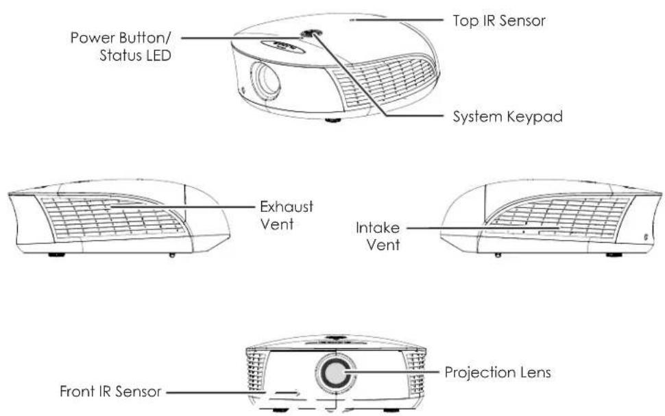
Figure 2-1 and Figure 2-2 show the key PD7170 components.
2.1 PD7170 at a Glance
Figure 2-1. PD7170 Front/Side View
• TOP IR SENSOR
Receives infrared signals from the remote control unit.
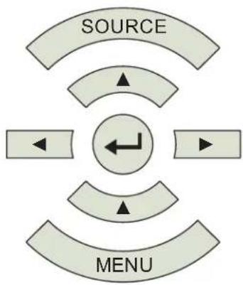
- SYSTEM KEYPAD
Provides an alternative to using the remote control unit to select a source or navigate the on-screen display (OSD) controls.
SOURCE
Use this button to select a video source.
Cursor Buttons (▲, ◀, ▼, ▶)
Use these buttons to select items or settings, adjust settings or switch display patterns.
flowchart
graph TD
    A["SOURCE"] --> B["Arrow Left"]
    B --> C["Arrow Right"]
    C --> D["Arrow Down"]
    D --> E["Arrow Up"]
    E --> F["Arrow Left"]
    F --> G["Arrow Right"]
    G --> H["Arrow Down"]
    H --> I["Arrow Up"]
    I --> J["Arrow Left"]
    J --> K["Arrow Right"]
ENTER ( )
Press to select a highlighted menu item or confirm a changed setting.
When no menu is present on-screen, press ENTER to access the motorized lens focus control. Press ENTER again to access the motorized lens zoom control. Press ENTER yet again to access the motorized lens shift control.
Use the ▲ and ▼ buttons to adjust focus, zoom or vertical lens position. Use the ◀ and ▶ buttons to adjust horizontal lens position.
MENU
Press this button to show or hide the OSD menus.
• POWER BUTTON/STATUS LED
Indicates projector status as follows:
- Solid green = AC power present, ready to turn on (lamp not lit)
- Flashing green = lamp is warming up or cooling down; keypad functions not allowed
- Off = Lamp lit, projector functioning normally
- Alternating green/red = Lamp problem (door open, unable to strike, end of life), user intervention likely to fix problem
- Flashing red = Over temperature, user intervention (clear vents, turn on AC) may fix problem
- Solid red = Error that requires servicing (fan fail, Power-on self-test fail etc.)
- EXHAUST VENT
Warm air exits the projector through this vent. Ensure that it is not blocked.
- INTAKE VENT
Internal fans draw cool air into the projector through this vent.
• PROJECTION LENS
The inside of the lens barrel is threaded to accommodate a standard, 72-mm lens filter. For example, with a smaller screen you can install a neutral-density filter to reduce the overall light output.
If needed, a light shield accessory is provided with the lens to minimize stray light emissions. (Use it only when the vertical offset is 50% of the screen height or greater.) The light shield attaches to the end of the lens (or to the filter, if used).
- FRONT IR SENSOR
Receives infrared signals from the remote control unit.

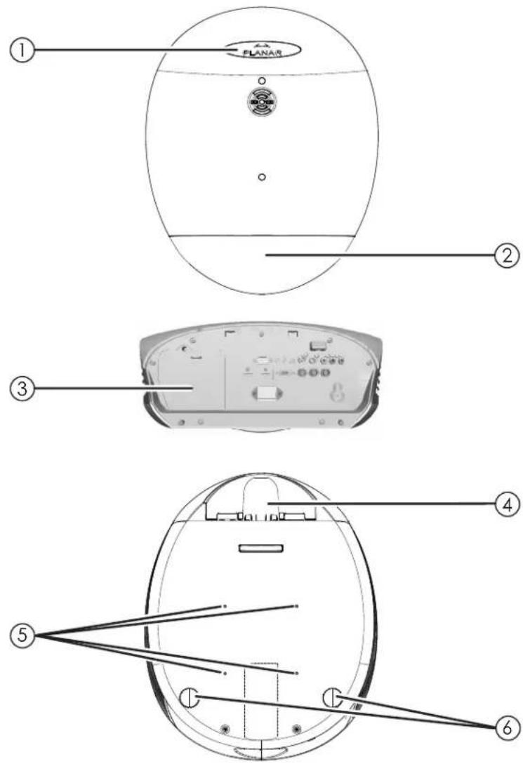
Figure 2-2. PD7170 Rear/Bottom/Top View
- PLANAR LOGO BADGE
- REAR COVER
Remove to access connectors.
- LAMP MODULE COVER
Remove this cover to access the lamp compartment.
- CABLE OPENING
Pass cables through this opening.
- CEILING MOUNT HOLES
Use these to attach the ceiling bracket to the projector.
- ADJUSTABLE FEET
Use these when the projector is installed in a table-top configuration to level the image and/or adjust the projection angle.
2.2
PD7170 Rear Panel
Figure 2-3 shows the PD7170 rear panel.
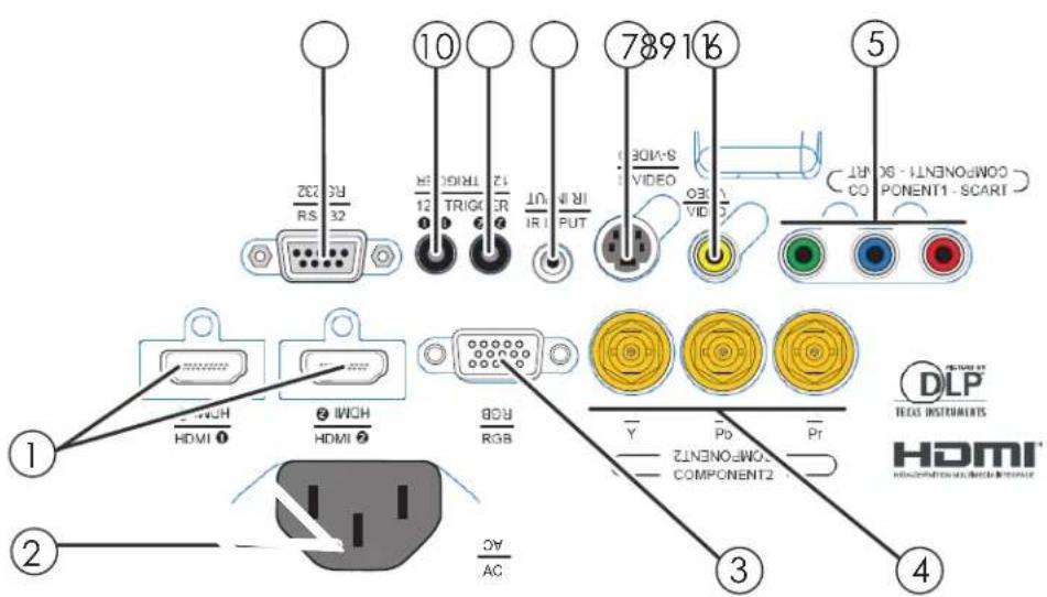
Figure 2-3. PD7170 Rear Panel
1. HDMI 1 (Digital)
HDMI 2 (Digital)
HDCP-compliant digital video inputs for connecting an HDMI or DVI source.
2. POWER INPUT (100 to 240 VAC)
Connect the PD7170 to power here.
3. RGB
Provides a standard, 15-pin VGA-style connection to either an RGB or component high-definition source, or to a personal computer. The PD7170 automatically detects the input signal resolution.
4. COMPONENT 2
Three BNCs for connecting component (YPbPr) video sources.
5. COMPONENT 1/SCART (RCA connectors)
Standard- or high-definition (480i/480p/576i/576p/720p/1080i/1080p) Component (YPrPb) input for connecting a DVD/HD-DVD/BD player, HD set-top box or other SD/HD source. Also provides RGB input for RGBS sources.
6. VIDEO
Standard composite video input for connecting a VCR, laser disc player or other composite video source. Also provides composite sync input for RGBS sources.
7. S-VIDEO
A standard S-Video input for connecting a DVD player, satellite receiver or Super VHS (S-VHS) VCR.
8. IR INPUT
Wired input from a Niles- or Xantech-compatible, infrared (IR) repeater system.
Provides 12 (+/- 1.5) volt switched output for screen relays with 250mA current capacity and short protection.
10. TRIGGER 1
Provides 12 (+/- 1.5) volt switched output for screen relays with 250mA current capacity and short protection.
11.RS-232
A female, 9-pin D-sub connector for interfacing with a PC or home theater automation/control system.
Figure 2-4 shows the PD7170 remote control, and the paragraphs that follow describe its functionality.
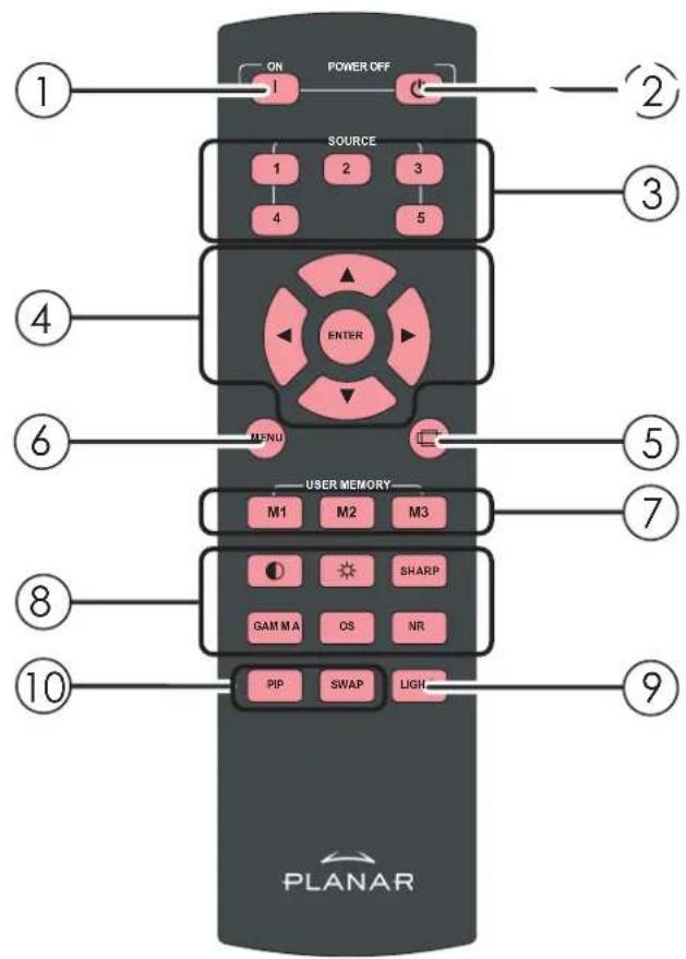
Figure 2-4. PD7170 Remote Control
2.3
PD7170 Remote Control
1. ON
Use this button to turn the projector on.
2. OFF
Use this button to turn the projector off.
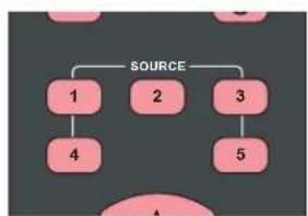
3. Source Selection Buttons (1-5):
Press to select a video source. By default, these buttons are assigned as follows: 1 = HDMI 1; 2 = HDMI 2; 3 = Component 1; 4 = S-Video; 5 = Video. However, you can assign each button to any source you wish.
4. Cursor Buttons (▲, ◀, ▼, ▶)
Use these buttons to select items or settings, adjust settings or switch display patterns.
ENTER
Press to select a highlighted menu item or confirm a changed setting.
When no menu is present on-screen, press ENTER to access the motorized lens focus control. Press ENTER again to access the motorized lens zoom control. Press ENTER yet again to access the motorized lens shift control.
Use the ▲ and ▼ buttons to adjust focus, zoom or vertical lens position. Use the ◀ and ▼ buttons to adjust horizontal lens position.
5. Aspect Ratio Selection Button
Press this button repeatedly to select one of the following aspect ratios:
16:9: For viewing 16:9 DVDs or HDTV programs in their native aspect ratio. Letterbox: For viewing LaserDisc movies or non-anamorphic DVDs on a 16:9 screen.
4 : 3: Scales the input signal to fit 4:3 sources in the center of the screen.
4:3 Narrow: Scales the input signal to fit 4:3 sources in the center of the screen when using an anamorphic lens.
Native: Displays source image in its native resolution without re-sizing or overscan.
6. MENU
Press this button to show or hide the OSD controls.
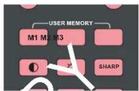
7. Memory Preset Buttons (M1 / M2 / M3)
Press to recall settings for the current input from one of three memory presets. By default, these buttons are assigned as follows: M1 = User Memory 1; M2 = User Memory 2; 3 = ISF Night. However, you can assign each button to any memory preset you wish.
8. Picture Adjustment Buttons:
Contrast
Press to adjust white level.
Brightness
Press to adjust black level.
Sharpness (SHARP)
Press to adjust sharpness.
Gamma (GAMMA)
Press to select a gamma curve.
Overscan (OS)
Press to select an overscan mode.
Noise Reduction (NR)
Press to adjust noise reduction level.
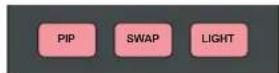
9. LIGHT
Press momentarily to activate remote backlighting. Press and hold for
5 to 7 seconds to illuminate the projector rear panel, to facilitate
connecting cables in a dark room.
10. Picture-In-Picture (PIP) Controls:
PIP
Press repeatedly to activate/deactivate PIP mode or select the desired PIP image source.
SWAP
Press to swap the PIP image with the active source image.
Notes:
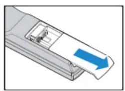
To install batteries in the remote control:
- Slide the battery compartment cover in the direction of the arrow to remove it.
- Install two AA batteries with the correct polarity.
-
Replace the cover.
-
natural_image
Illustration of a device with a blue arrow pointing to a paper sheet (no text or symbols)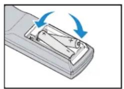
natural_image
Illustration of a remote control device with two blue arrows indicating rotation or movement (no text or symbols)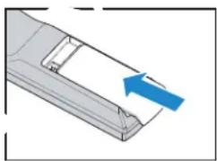
natural_image
3D diagram of a mechanical component with a blue arrow pointing to a section (no text or symbols)3.1
Remote Control
- Make sure that the battery polarities are correct when installing the batteries.
- Do not mix an old battery with a new one or different types of batteries.
- If you will not use the remote control for a long time, remove the batteries to avoid damage from battery leakage.
- In most situations, you can simply point the remote control at the screen which will reflect the IR signal from the remote back toward the IR receiver on the projector. In some cases, however, ambient conditions may prevent this. If so, point the remote control at the projector and try again.
- If the effective range of the remote control decreases, or it stops working, replace the batteries with new ones.
- The remote control may fail to operate if the infrared remote sensor is exposed to bright sunlight or fluorescent lighting.
Notes on Batteries
Notes on Remote Control Operation
- The projector's front IR receiver has a range of approximately 40 feet (12.19 meters); the top IR receiver has a range of approximately 20 feet (6.10 meters). Figure 3-1 shows the reception angles of the front and top IR receivers.
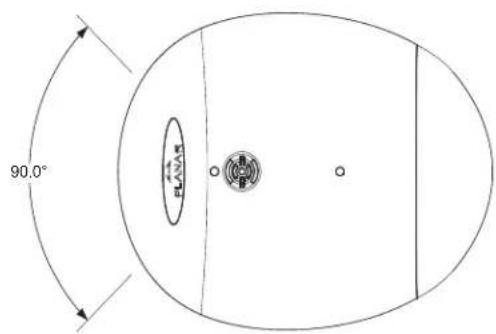
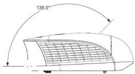
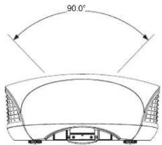
Figure 3-1. IR Reception Angles
Table 3-1 gives a quick overview of the PD7170 installation process. The sections following this one provide detailed instructions.
3.2
Quick Setup

Note
Installation should be performed by a qualified custom video installation specialist.
Table 3-1. Installation Overview
| Step Procedure | For Details, Refer to page... |
| 1 Choose a location for the projector 16 | |
| 2 Install the projection lens (if standard lens will not be used) | 21 |
| 3 Mount the projector 23 | |
| 4 Connect signal sources to the PD7170 25 | |
| 5 Connect external controller to RS-232 port and/or IR repeater system (optional) | 29 |
| 6 Connect 12-volt trigger output to retractable screen or other, +12V trigger-activated equipment (optional) | 30 |
| 7 Apply power to the projector 31 | |
| 8 Primary lens adjustments: projected image size (zoom), position (shift) and focus | 19, 31 |
| 9 Change the OSD Language (optional) 32 | |
| 10 For rear-screen and/or ceiling-mount installations, select the proper picture orientation | 33 |
| 11 Projector calibration: adjust the followingfor each input; save settings when finished: Aspect ratio Brightness Contrast Color level Tint Input position | 39 |
3.3
Installation
Considerations
Installation Type ▶
Proper installation of your projector will ensure the quality of your display. Whether you are installing a projector temporarily or permanently, you should take the following into account to ensure your projector performs optimally.
Choose the installation type that best suits your needs: front or rear screen, floor mount or inverted mount. Table 3-2 compares these various installation methods.
Table 3-2. Projector Installation Options
| Advantages Considerations | |
| Front Screen, Floor Mount Installation | |
| Easy to set upCan be moved or changed quicklyEasy to access | Shares floor space with audience |
| Front Screen, Inverted Mount (ceiling) Installation | |
| Does not take up audience spaceProjector is unobtrusiveProjector cannot be accidentally moved | Installation is more permanentProjector access is more difficult |
| Rear Screen, Floor Mount Installation | |
| Projector is completely hiddenProjector is easily accessedUsually good ambient light rejection | Requires separate roomInstallation cost is usually higher |
| Rear Screen, Inverted Mount (ceiling) Installation | |
| Projector is completely hiddenUsually good ambient light rejection | Requires separate roomInstallation cost is usually higher |
| Rear Screen, Floor Mount with Mirror | |
| Projector is completely hiddenUsually good ambient light rejectionRequires less space behind screen than other rear screen installations | Requires separate roomInstallation cost is usually higher |
In general, minimize or eliminate light sources directed at the screen. Contrast ratio in your images will be noticeably reduced if light directly strikes the screen, such as when a shaft of light from a window or floodlight falls on the image. Images may then appear washed out and less vibrant.
Throw distance is the distance measured from the front of the projector to the screen. This is an important calculation in any projector installation as it determines whether or not you have enough room to install your projector with a desired screen size and if your image will be the right size for your screen.
You can quickly estimate the throw distance by taking the width of the screen and multiplying it by the lens throw ratio; see Figure 3-2. The result of this calculation tells you roughly how far back the projector should be positioned from the screen in order to project a focused image large enough to fill the screen.
◀ Ambient Light
◀ Throw Distance
Estimating Throw Distance
Throw Distance (TD) = Screen Width (w) x Lens Throw Ratio
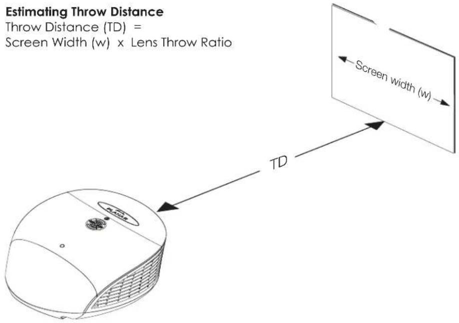
Figure 3-2. Estimating Throw Distance
Table 3-3 lists the available lens options for the PD7170 and their associated throw ratios.
Table 3-3. PD7170 Lens Options and Throw Ratios
| Lens Option Throw Ratio | Throw Range in inches, with a 96x54-inch (1.78:1) Screen | |
| Minimum Maximum | ||
| Z80 1.52 - 1.82 145.92 | 174.72 | |
| Z100 (standard) 1.82 | -2.28 174.72 218.88 | |
| Z200 2.28 - 3.04 218.88 | 291.84 | |
| Z400 3.04 - 4.56 291.84 | 437.76 | |
| Z500 4.56 - 7.09 437.76 | 680.64 | |
Vertical and Horizontal Position
Proper placement of the projector relative to the screen will yield a rectangular, perfectly-centered image that completely fills the screen.
Ideally, the projector should be positioned perpendicular to the screen and in such a way that the lens center is aligned with either the top or bottom edge of the screen area, and centered horizontally. See Figure 3-3.
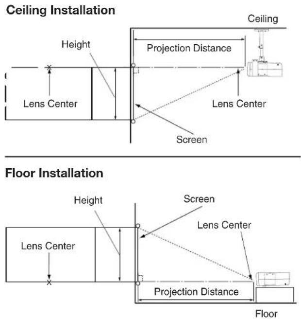
Figure 3-3. Projector Placement
You can use the lens shift controls on the projector to center the image on the screen. Lens shift is generally expressed as a percentage of the screen height or width, as shown in Figure 3-4 and Figure 3-5.
◀ Vertical and Horizontal Lens Shift
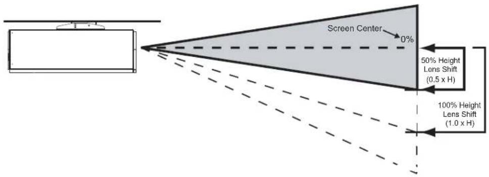
Note: This is a general example of lens shift. Lenses vary in their shift capabilities. No particular lens or projector is used in this example.
Figure 3-4. Vertical Lens Shift (Example Only)
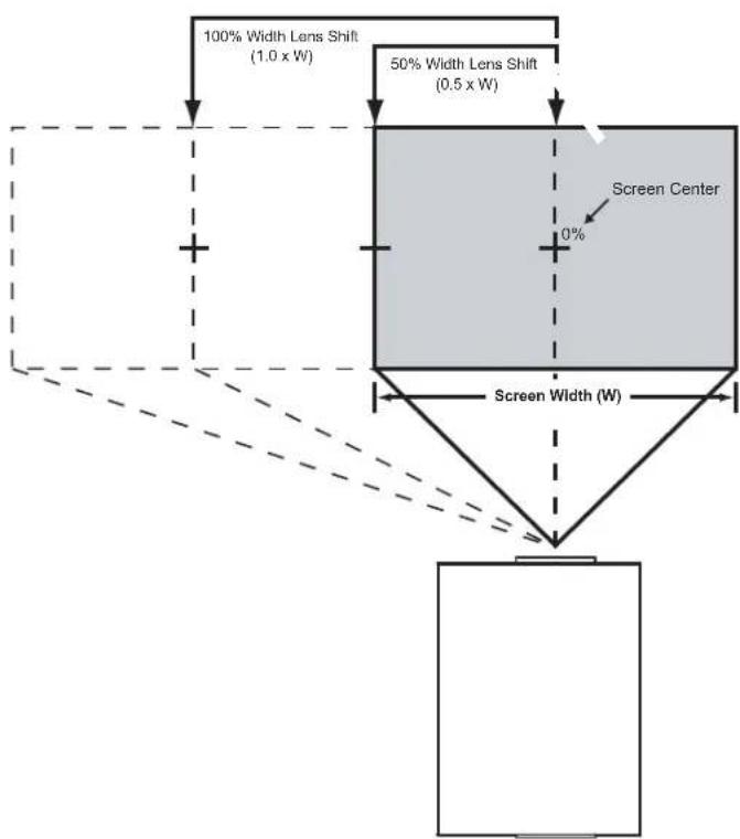
Note: This is a general example of lens shift. Lenses vary in their shift capabilities. No particular lens or projector is used in this example.
Figure 3-5. Horizontal Lens Shift (Example Only)
Vertical Lens Shift: The PD7170 provides up to 65% of vertical lens shift up or down. For example, with a 100 x 56 inch (1.78:1) screen, you can shift the image up to 36.40 inches (0.92 meters) above or below the screen center.
Horizontal Lens Shift: The PD7170 provides up to 30% of horizontal lens shift left or right. For example, with a 100 x 56 inch (1.78:1) screen, you can shift the image up to 30.00 inches (0.76 meters) left or right of the screen center.

Note
- With no vertical or horizontal lens shift, the lens center and screen center are aligned with each other.
- Vertical shift limits are percentages of the screen height. Horizontal shift limits are percentages of the screen width.
- Vertical lens shift figures are for ceiling mount configurations. For floor installations (where the projector is upright), reverse the up/down vertical lens shift percentages.
Folded Optics
In rear-screen applications where space behind the projector is limited, a mirror may be used to fold the optical path, as shown in Figure 3-6. The position of the projector and mirror must be accurately set. If you are considering this type of installation, contact your dealer for assistance.
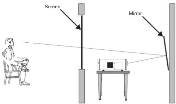
Figure 3-6. Folded Optics
Other Considerations ▶
Other considerations and tips that can help improve your installation:
- Keep the ambient temperature constant and below 35°C (95°F). Keep the projector away from heating and/or air conditioning vents. Changes in temperature may cause drifts in the projector circuitry, which may affect performance.
- Keep the projector away from devices that radiate electromagnetic energy such as motors and transformers. Common sources of these include slide projectors, speakers, power amplifiers and elevators.
The PD7170 is shipped with the standard (1.82 - 2.28) projection lens pre-installed. If your installation requires a different lens, proceed as follows to remove the standard lens and replace it with the required one.
3.4 Lens Replacement
- Using a Phillips screwdriver, remove the two screws holding the projector front cover in place.
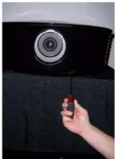
natural_image
Hand holding a red object next to a black textured surface with a circular emblem (no text or symbols visible)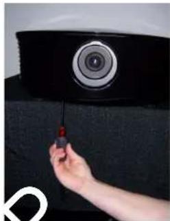
natural_image
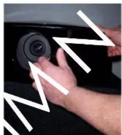
Close-up of a hand using a screwdriver to adjust a black camera lens on a textured surface (no text or symbols visible)- Gently pull the cover away from the projector at each side to detach it.
natural_image
Close-up of hands adjusting a camera lens on a car (no visible text or symbols)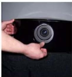
natural_image
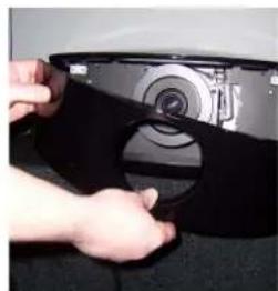
Close-up of hands holding a camera lens on a car tire (no visible text or symbols)- Remove the cover and set it aside.
natural_image
Close-up of hands installing a black plastic cover onto a camera module (no text or symbols visible)- Locate the lens release lever, above the lens cavity.
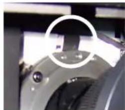
natural_image
Close-up of a mechanical component with a circular annotation highlighting a section (no visible text or symbols)- Press and hold the lens release button. Then, grasp the lens by the front and rotate it counterclockwise until it stops (approximately 30 degrees).
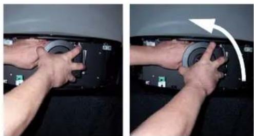
natural_image
Two-panel photo showing hands installing or adjusting a car interior panel with a white arrow indicating rotation (no text or symbols visible)- Pull the lens straight out to remove it.
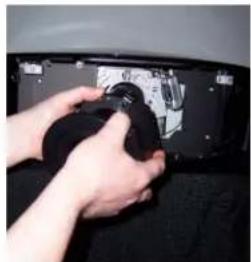
natural_image
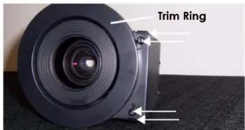
Close-up of hands installing or adjusting a component on a black panel (no visible text or symbols)- Remove the trim ring attached to the motor housing on the lens you just removed. To do this, remove the two screws and two metal clips that hold it in place.
-
Attach the trim ring to the motor housing on the new lens.
-
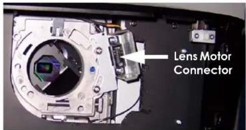
Note that the lens mount flange has a female socket connector for the lens motor on the right side of the flange. (The lens assembly motor has a male socket connector that mates with this connector.)
-
Hold the replacement lens assembly with the motor facing to the right. Carefully insert the back of the lens assembly into the hole in the lens flange.
-
Slightly rotate the lens assembly counterclockwise to align the motor connectors on the lens and lens flange. Gently push the lens assembly in until it is seated flush against the flange and the motor connectors have seated.
-
Carefully rotate the lens assembly clockwise until it stops and the metal clips at the back of the lens "click" into place.
-
Replace the projector front cover.
There are several methods for mounting the projector. Depending on your chosen installation, one method may be more suitable than another.
In typical front and rear screen installations, the projector can be mounted to a secure and level surface such as a table or cart. Carts are useful when moving a projector during a presentation or from site to site. If possible, lock the wheels when it's in position to prevent it from being moved during a presentation.
For fixed installations, and for those that want the projector out of sight or have a limited space for projector and audience, you can invert the PD7170 and suspend it from the ceiling using a specially-designed ceiling mount fixture.

Note
Use only the Planar-approved ceiling mount kit designed for your projector. Install the mount kit according to the instructions provided with it.
If the screen is significantly higher or lower than the projector, you can also tilt the projector at a slight angle. In a ceiling installation, you do this by adjusting the ceiling mount.
For a floor installation, turn the adjustable feet at the bottom of the projector to adjust the projection angle.
If you do this, you may need to vertically shift the image to compensate. For detailed instructions, refer to Lens Adjustments on page 31.
Proceed as follows to connect the PD7170 to your video sources, external controller(s) – if present – and AC power.
When connecting your equipment:
- Use the correct signal cables for each source.
- Ensure that the cables are securely connected. Tighten the thumbscrews on connectors that have them.
3.5
Mounting the PD7170
◀ Floor Mounting (Upright)
Ceiling Mounting (Inverted)
Adjusting the Projection Angle
3.6
Connections to the PD7170
Connector Panel Access
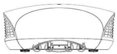
Using a flat-blade screwdriver, loosen the four screws holding the rear compartment cover in place.
Then, remove the rear compartment cover by tilting it upward.
natural_image
Architectural line drawing of a modern building facade with curved roof and structural elements (no text or symbols)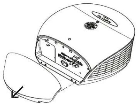
natural_image
Technical line drawing of a device with internal components and a directional arrow (no text or symbols)Connect your video sources to the PD7170 as shown and described in the sections that follow.
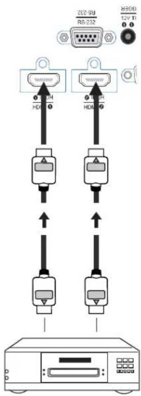
HDMI/DVI Connections: See Figure 3-7.
Connecting Source Components to the PD7170

Tip
Use the HDMI inputs whenever possible. This ensures the highest video quality because the signal is carried in the digital domain throughout the entire signal path, from source component output into the projector.
HDMI or DVI Source(s)
(BD/HD-DVD/DVD Player,
HD Set Top Box,
Game Console etc.)
Figure 3-7. HDMI/DVI Source Connections
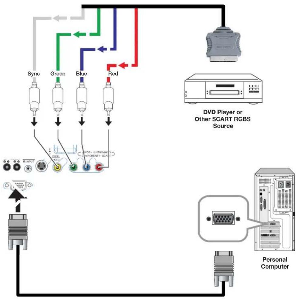
RGB Connections: Connect your personal computer or other RGB source to the RGB input.
Optionally, if the source outputs RGB with composite sync, connect the green, blue and red outputs to the Y, Pb and Pr terminals on the COMPONENT 1/SCART input and the sync output to the VIDEO input.
See Figure 3-8.
flowchart
graph TD
    A["Personal Computer"] --> B["DVd Player or Other SCART RGBS Source"]
    B --> C["Sync"]
    B --> D["Green"]
    B --> E["Blue"]
    B --> F["Red"]
    C --> G["IR INPUT"]
    D --> H["RGB"]
    E --> I["RGB - LNB/RGB COMPONENT1 - PCA"]
    F --> J["Red"]
Figure 3-8. RGB Connections
Component Video Connections: Connect your component video sources to the COMPONENT 1/SCART, COMPONENT 2 or RGB inputs as shown in Figure 3-9.
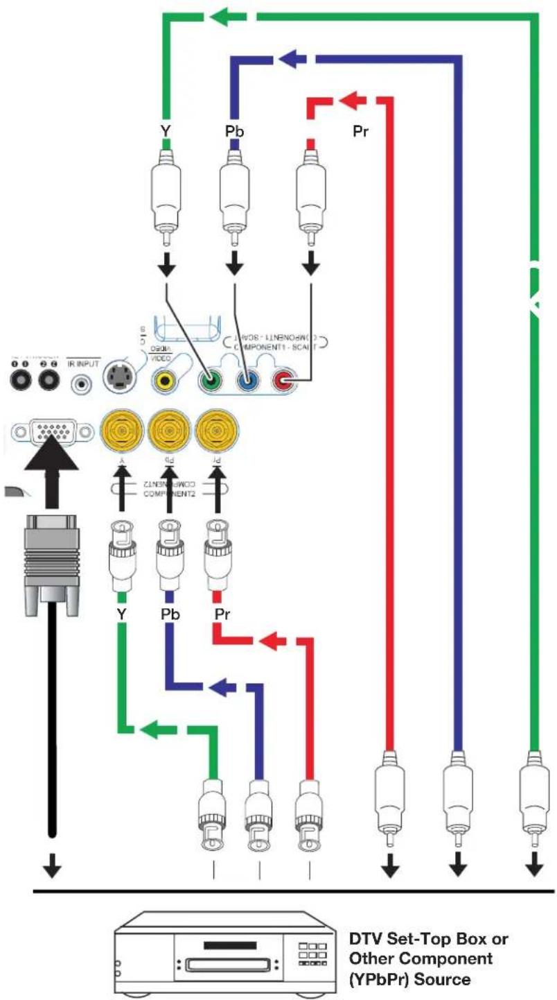
flowchart
graph TD
    A["IR INPUT"] --> B["PTV"]
    B --> C["Video"]
    C --> D["JPDS - LLNENO@W0 COMPONENT1 - SCALE"]
    D --> E["Yellow Core"]
    D --> F["Yellow Core"]
    D --> G["Yellow Core"]
    D --> H["Blue Core"]
    D --> I["Red Core"]
    D --> J["Green Core"]
    D --> K["Green Core"]
    D --> L["Blue Core"]
    D --> M["Blue Core"]
    D --> N["Red Core"]
    D --> O["Red Core"]
    D --> P["Green Core"]
    D --> Q["Green Core"]
    D --> R["Y"]
    D --> S["Pb"]
    D --> T["Pr"]
    D --> U["I/O"]
    D --> V["IP"]
    style A fill:#f9f,stroke:#333
    style B fill:#ccf,stroke:#333
    style C fill:#cfc,stroke:#333
    style D fill:#fcc,stroke:#333
    style E fill:#ffc,stroke:#333
    style F fill:#cfc,stroke:#333
    style G fill:#cfc,stroke:#333
    style H fill:#cfc,stroke:#333
    style I fill:#cfc,stroke:#333
    style J fill:#cfc,stroke:#333
    style K fill:#cfc,stroke:#333
    style L fill:#cfc,stroke:#333
    style M fill:#cfc,stroke:#333
    style N fill:#cfc,stroke:#333
    style O fill:#cfc,stroke:#333
    style P fill:#cfc,stroke:#333
    style Q fill:#cfc,stroke:#333
    style R fill:#cfc,stroke:#333
    style S fill:#cfc,stroke:#333
    style T fill:#cfc,stroke:#333
    style U fill:#cfc,stroke:#333
Figure 3-9. Component Video Connections
Composite/S-Video Connections: Connect your Composite and S-Video sources to the PD7170 as shown in Figure 3-10.
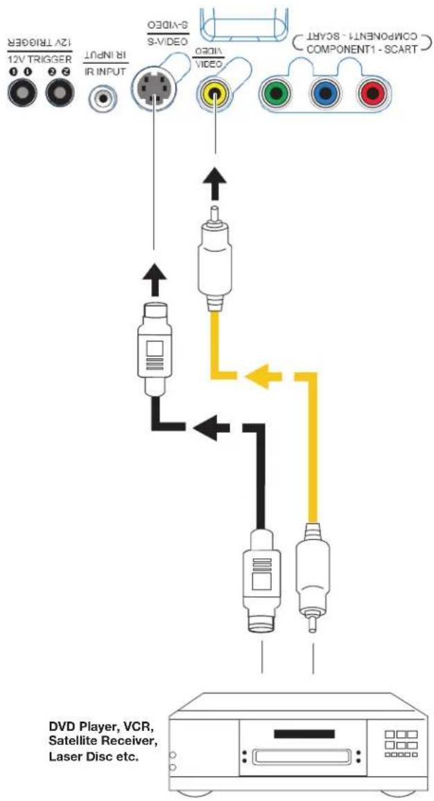
Figure 3-10. Composite and S-Video Connections
Connect a PC or home theater control/automation system (if present) to the RS-232 port on the PD7170; see Figure 3-11. Use a standard, 9-pin serial cable, wired straight-through.
RS-232 Controller Connection
For more information about using this connection, refer to Serial Communications on page 69.
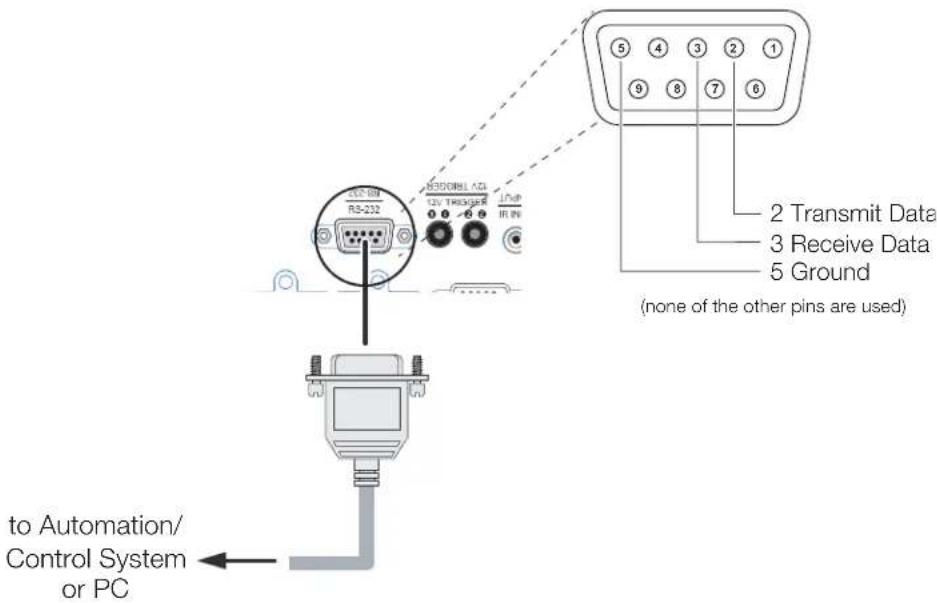
Figure 3-11. RS-232 Control System Connection
Connecting 12-Volt Trigger Output to External Theater Equipment
If your home theater contains a retractable screen, screen mask or other 12-volt trigger-activated equipment, connect it to the 12-volt trigger output(s) as shown in Figure 3-12.
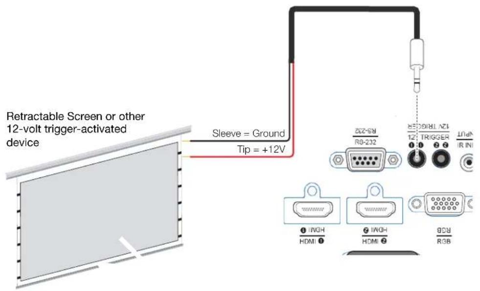
Figure 3-12. 12-Volt Trigger Output Connection
Connecting an External IR Receiver
If infrared signals from the remote control cannot reach the projector due to excessive distance or obstructions such as walls or cabinet doors, you can connect an external IR repeater system to the IR INPUT on the PD7170 to extend the range of the remote control. See Figure 3-13.
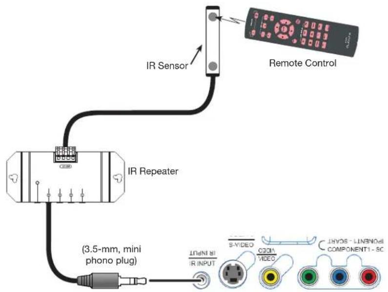
flowchart
graph TD
    A["IR Sensor"] --> B["Remote Control"]
    B --> C["IR Repeater"]
    C --> D["(3.5-mm, mini phono plug)"]
    D --> E["VIDEO/INJ/IR INPUT"]
    E --> F["COMPONENT1-SC"]
    style A fill:#f9f,stroke:#333
    style B fill:#ccf,stroke:#333
    style C fill:#cfc,stroke:#333
    style D fill:#fcc,stroke:#333
    style E fill:#cff,stroke:#333
    style F fill:#ffc,stroke:#333
Figure 3-13. External IR Receiver Connection
The PD7170 ships with various types of AC power cords. Choose the one that is appropriate to your locale.
Plug the female end of the power cord into the AC receptacle on the rear of the projector (AC 100V \~ 240V); see Figure 2-3. Then, connect the other end to your AC power source.
- Turn on your source components.
- Press the ON button on the remote control to turn on the PD7170. The LED flashes green to indicate that it is warming up.
- When the projector is ready for use, the LED turns off.
The PD7170 gives you a great deal of control over the picture size, position and focus.
To access the motorized lens focus control, do either of the following:
- Press MENU on the remote control. Select Control from the Main Menu, then press ▲ or ▼ to highlight Lens Control. Press ◀ or ▶ to highlight Focus and press ENTER.
- When no menu is present on-screen, press ENTER (⇐) on the system keypad or remote control unit.
Then, use the ▲ button to focus the projected image nearer or the ▼ button to focus the projected image farther away.
- Press MENU on the remote control. Select Control from the Main Menu, then press ▲ or ▼ to highlight Lens Control. Press ◀ or ▶ to highlight Zoom and press ENTER.
- When no menu is present on-screen, press ENTER (←) on the system keypad or remote control unit twice.
Then, use the ▲ button to make the picture larger (zoom in) or the ▼ button to make the picture smaller (zoom out).
- Press MENU on the remote control. Select Control from the Main Menu, then press ▲ or ▼ to highlight Lens Control. Press ◀ or ▶ to highlight Lens Shift and press ENTER.
- When no menu is present on-screen, press ENTER (←) on the system keypad or remote control unit three times.
Then, use the ▲ and ▼ buttons to adjust the vertical lens position or the ◀ and ▶ buttons to adjust the horizontal lens position.
Connecting to AC Power
3.7
Turning on the Power
3.8
Lens Adjustments
◀ Focus
◀ ZoomTo access the motorized len
◀ Lens ShiftTo access the motorized
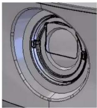
Installing the Optional Stray Light Shield: For installations that require significant vertical lens shift (50% or more of the screen height), a lens shield is provided with the PD7170 that minimizes stray light around the image.
The light shield attaches to threads at the end of the lens. Or, if you have installed a lens filter, you can attach the light shield to it.
To install or remove the light shield, squeeze the two side "wings" to snap it into place or release it.
natural_image
Technical line drawing of a circular mechanical component with concentric rings and internal features (no text or symbols)
Do not use the stray light shield unless the amount of vertical lens shift exceeds 50 per cent of the screen height.
3.9 Changing the OSD Language
When you turn on the PD7170 for the first time, the OSD Language Menu appears.
The PD7170 can display the menus in English, French, German, Italian, Spanish, Swedish, Traditional Chinese, Simplified Chinese, Japanese, Korean, Portuguese or Russian.
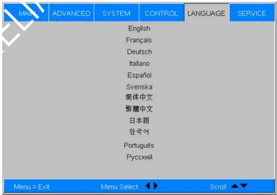
Press ▲ or ▼ to select a language. Then, press ENTER to confirm your selection.
If the PD7170 is installed behind the screen, you must change the picture orientation to match the installation method. To do this, press MENU on the remote control. Then, select System from the Main Menu.
If the projector is used in a rear-projection application (see Figure 3-6), press ▼ repeatedly to select Rear Projection from the System Menu. Press ◀ or ▶ to set it to On.
If the projector is ceiling-mounted, the PD7170 automatically inverts the image. If this automatic inversion is not desired, select Ceiling Mode from the System Menu and set it to Off.
3.10
Adjusting the Picture Orientation
Rear Projection
Ceiling Mode
Notes:
Operation
Press M1, M2 or M3 to recall settings from a memory preset. Then, press ENTER to confirm your selection. Or, to cancel the operation, press ▶ to select Cancel and press ENTER.
You can assign each of these three buttons to any of four memory presets. For more information, refer to M1 Key / M2 Key / M3 Key on page 59.
flowchart
graph TD
    A["M1"] --> B["M2"]
    B --> C["M3"]
    C --> D["O"]
    D --> E["SHARP"]
    E --> F["Output"]
    style A fill:#f9f,stroke:#333
    style B fill:#f9f,stroke:#333
    style C fill:#f9f,stroke:#333
    style D fill:#f9f,stroke:#333
    style E fill:#f9f,stroke:#333
    style F fill:#f9f,stroke:#333
4.1 Selecting Video Memory
Press the aspect ratio (☐) button to select the appropriate aspect ratio for the type of program material being viewed. For more information, refer to Table 4-2.
4.2 Selecting an Aspect Ratio
When you turn on the PD7170, it switches to the last selected input and looks for a valid signal.
Use these buttons on the remote control to select an input source directly. You can assign each of these five buttons to any input. The default assignments are: 1 = HDMI 1, 2 = HDMI 2, 3 = Component 1, 4 = S-Video, 5 = Video.
flowchart
graph TD
    A["SOURCE"] --> B["1"]
    A --> C["2"]
    A --> D["3"]
    B --> E["4"]
    C --> F["5"]
4.3 Selecting An Input Source
For more information, refer to 1 Key / 2 Key / 3 Key / 4 Key / 5 Key on page 59.
4.4
Using Picture-In-Picture (PIP)
For PIP purposes, there are three groups of inputs separated by their display modes:
• Video (SD) group: Video, S-Video and SCART inputs.
- Graphic (HD) group: Component 1, Component 2 and RGB inputs.
• Digital Video group: HDMI 1 and HDMI 2 inputs.
PIP shows one input from any of these groups within or beside one input from either of the other two groups.
- Press PIP to enable the PIP function. Once enabled, press PIP repeatedly to select the desired PIP source or turn PIP off.
- Press SWAP to swap the main and PIP images.
For more information, refer to PIP Position on page 57.
For each source, Table 4-1 shows which of the other sources are available as a PIP source.
Table 4-1. Available Main and PIP Source Combinations
| PIP Input Source | |||||||||
| VIDEO | S-VIDEO | SCART | COMP 1 | COMP 2 | RGB | HDMI 2 | HDMI 1 | ||
| Main Input Source | VIDEO | --- | √ √ | √ √ √ | |||||
| S-VIDEO | --- | √ √ | √ √ √ | ||||||
| SCART | --- | √ √ | √ √ √ | ||||||
| COMP 1 | √ √ | √ | - | - | - | √ | √ | ||
| COMP 2 | √ √ | √ | - | - | - | √ | √ | ||
| RGB | √ √ | √ | - | - | - | √ | √ | ||
| HDMI 2 | √ √ | √ √ √ | √ | - | - | ||||
| HDMI 1 | √ √ | √ √ √ | √ | - | - | ||||
| Notes:“ v' means that that source is available as a PIP source with a given main source; “-” means that it is not.2. Disabled sources (refer toSource Enableon page 56) are not available as PIP sources. | |||||||||
- Press the MENU button on the remote control or system keypad to display the Main Menu.
- There are six menus. Press to select a sub-menu.
- Press ▲ or ▼ to select a sub-menu item.
- For each sub-menu item, the currently-selected value appears in white text or is otherwise highlighted. Press ◀ or ▶ to choose a setting for that item, or press ENTER to go to another sub-menu.
- Press MENU to return to the previous menu.
- From the Main Menu, press MENU to turn off the OSD menu.
The PD7170 OSD menus are arranged hierarchically, as shown in Figure 4-1. Depending on the selected input source and signal characteristics, some menu options may not be available.
4.5
Using the On-Screen Menus
| Main | Aspect Ratio | 16:9, 4:3, Letterbox, 4:3 Narrow or Native |
| Memory | Recall Memory | |
| Save Settings | ||
| Save ISF | ||
| Brightness | 0 ... 50* ... 100 | |
| Contrast | ||
| Color Saturation | ||
| Color TinI | ||
| Sharpness | Sharpness | |
| Sharpness Mode(Simple or Advanced) | ||
| Horizontal Sharpness | ||
| Vertical Sharpness | ||
| Diagonal Sharpness | ||
| Sharpness Overshoot | ||
| Horizontal Texture | ||
| Vertical Texture | ||
| Diagonal Texture | ||
| Texture Overshoot | ||
| Noise Threshold | ||
| Noise Reduction | Noise Reduction | |
| Noise Reduction Mode(Simple or Advanced) | ||
| General Noise Reduction | ||
| Block Artifact Reduction | ||
| Mosquito Noise Reduction | ||
| Overscan Off, Crop or Zoom | ||
| Source Select | HDMI 1, HDMI 2, RGB,Comp. 1, Comp. 2, Video,S-Video or SCART | |
| PIP Select | Off, HDMI 1, HDMI 2, RGB,Comp. 1, Comp. 2, Video,S-Video or SCART | |
| Resync (press ENTER to execute) | ||
| Advanced | Color Space | Auto, REC709, REC601,RGB-PC or RGB-Video |
| Video Standard Auto, NTSC, PAL or SECAM | ||
| Gamma | CRT, Film, Video, Bright or Graphics | |
| Color Temperature | 5500K, 6500K, 7500K, 9300Kor Native | |
| DLP Frame Rate Auto, 48 Hz, 50 Hz or 60 Hz | ||
| Color Gamut | Auto, REC709, SMPTE-C, EBUor Native | |
| Dynamic Black On or Off | ||
| Adoptive Contrast On or Off | ||
| RGB Adjust | Red / Green / Blue Offset | |
| Red / Green / Blue Gain | ||
| Fine Sync | V. Position | |
| H. Position | ||
| Phase | ||
| Tracking | ||
| Sync Level | ||
| System | Source Enable On or | Off for each source |
| PIP Position | Top Left, Top Right, Bottom Left, Bottom Right, Picture-by-Picture or Split Screen | |
| Menu Position | Top Left, Top Right, Bottom Left, Bottom Right or Center | |
| Translucent Menu | 0% (opaque), 25%, 50% or 75% | |
| Lamp Power Economy or Standard | ||
| Blank Screen Logo, Black, Blue or White | ||
| Auto Power Off | On or Off Auto Power On | |
| Rear Projection | ||
| Ceiling Mode Auto, On or Off | ||
| Logo Display | On or Off | |
| Power On Chime | ||
| Control | Lens Control Focus, Zoom, Lens Shift | |
| 1 Key | HDMI 1, HDMI 2, RGB, Comp. 1, Comp. 2, Video, S-Video or SCART | |
| 2 Key | ||
| 3 Key | ||
| 4 Key | ||
| 5 Key | ||
| M1 Key | User Memory 1, User Memory 2, ISF Day or ISF Night | |
| M2 Key | ||
| M3 Key | ||
| Trigger 1 | Lamp, 16:9, Letterbox, 4:3, 4:3 Narrow or RS-232 | |
| Trigger 2 | ||
| Change Remote Code | Set 1 or Set 2 | |
| Auto Source On or Off | ||
| Language | English, French, German, Italian, Spanish, Swedish, Traditional Chinese, Simplified Chinese, Japanese, Korean, Portuguese or Russian | |
| Service | Model Name | (read-only) |
| Unit Serial Number | ||
| Software Version | ||
| Active/PIP Source | ||
| Pixel Clock | ||
| Signal Format | ||
| H/V Refresh Rate | ||
| Lamp Hours | ||
| Lamp Hour Reset Reset? (Yes or No) | ||
| Factory Reset | Reset Everything? (Yes or No) | |
| Blue Only On or Off | ||
| Test Patterns On or Off | ||
| Altitude Auto or High | ||
Figure 4-1. PD7170 OSD Menu Structure
The PD7170 Main Menu, shown in Figure 4-2, provides access to the most commonly-used projector functions.
< Main

Note
- For best results, Planar recommends that you set DynamicBlack to Off before adjusting Brightness, Contrast and other image quality settings in this menu (refer to DynamicBlack on page 52). After you have completed the initial calibration, set DynamicBlack to On if desired.
- Image controls only operate on the active source. To adjust the PIP source, switch to the PIP source (thereby making it the active source), adjust the controls and then switch back.
| MAIN | ADVANCED | SYSTEM | CONTROL | LANGUAGE | SERVICE | |
| Aspect Ratio | 16:9 | Letterbox | 4:3 | 4:3-Narrow | Native | |
| Memory | Enter | |||||
| Brightness | 100 | |||||
| Contrast | 100 | |||||
| Color Saturation | 100 | |||||
| Color Tint | 100 | |||||
| Sharpness | Enter | |||||
| Noise Reduction | Enter | |||||
| Overscan | OFF | Crop | Zoom | |||
| Source Select | Enter | |||||
| PIP Select | Enter | |||||
| Resync | Enter | |||||
Figure 4-2. PD7170 Main Menu
Aspect Ratio: To change the aspect ratio (size and shape) of the projected image, press ▲ or ▼ to highlight Aspect Ratio. Use the ◀ or ▶ buttons to select the appropriate aspect ratio for your screen size, installed lens configuration and the type of program material being viewed, then press ENTER; refer to Table 4-2.
Table 4-2. Aspect Ratio Settings
| Aspect Ratio Setting | Description | Aspect Ratio of Source Signal | Geometry of Projected Image | |
| With Standard Lens (1.78:1 Screen) | With Anamorphic Lens (2.35:1 Screen) | |||
| 16:9 | 16:9 linearly scales the source active image horizontally and vertically to fill a 16:9 screen. | 16:9 | 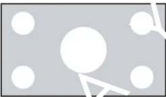 | 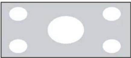 |
| 4:3 | 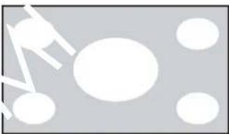 | 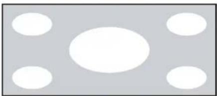 | ||
| 4:3 | 4:3 linearly scales the source active image horizontally and vertically to fill a 4:3 screen. | 16:9 | 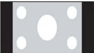 | 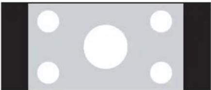 |
| 4:3 | 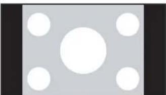 | 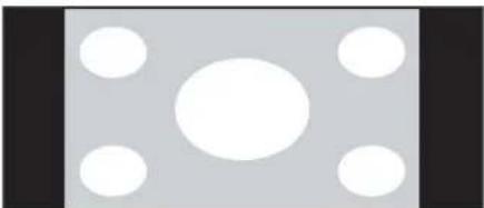 | ||
| Letterbox | Letterbox mode scales (zooms in on) a 4:3 image linearly (by the same amount on all sides) to fill a 16:9 display, cropping the top and bottom of the image. | 16:9 | 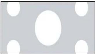 | 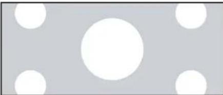 |
| 4:3 | 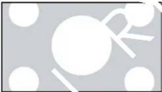 | 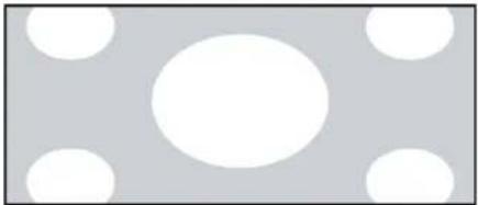 | ||
| 4:3 Narrow | 4:3 Narrow linearly scales the source active image horizontally, so that a 4:3 source has the correct aspect ratio when using an anamorphic lens. | 16:9 | 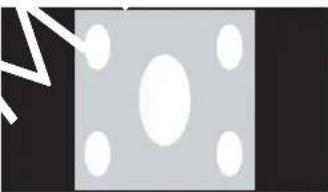 | 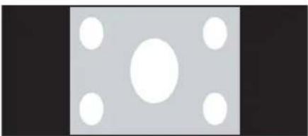 |
| 4:3 | 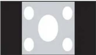 | 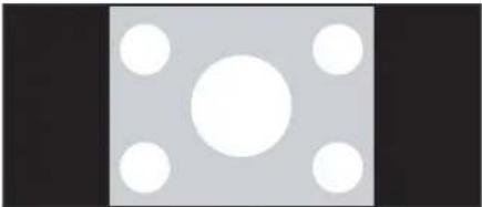 | ||
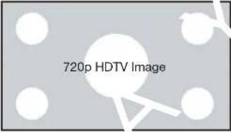
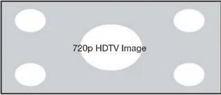
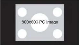
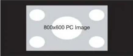
| Native | Select Native to display the source signal in its native resolution, centered in the display area with no re-sizing or overscan. | 16:9 | 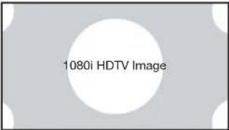 | 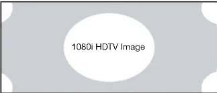 |
 |  | |||
| With SDTV and EDTV sources, the PD7170 scales the image horizontally to achieve a 16:9 aspect ratio. | 4:3 | 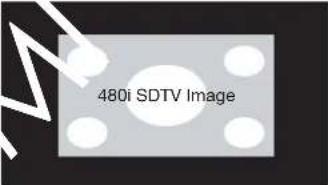 | 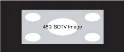 | |
 |  | |||
Memory: Select Memory from the Main menu, then press ENTER to recall image quality settings previously saved, or to save changed settings in any of four memory locations.
- Recall Memory: Select Recall Memory from the Memory menu to recall saved image quality settings. Unless you select Default (see below), this control affects all sources, not just the active source.
- User Memory 1 and User Memory 2 contain the factory default settings when the projector is initially turned on.
- When you recall the ISF Day or ISF Night memory settings, all settings associated with these stored values are grayed out. This prevents unintended adjustments from being made. To remove this restriction, choose User Memory 1 or User Memory 2.
ISF Day and ISF Night are grayed out unless these custom settings have already been saved.
- Choose Default to restore the factory-default settings for the active source only. The other sources are unaffected.
- Save Settings: Select Save Settings from the Memory menu to save any image-related settings you have changed to User Memory 1 or User Memory 2.
The following items are saved (for all sources, not just the active source):
- Brightness / Contrast
• Color Saturation / Color Tint - Sharpness (all settings in sub-menu)
- Noise Reduction (all settings in sub-menu)
- Color Space
- Video Standard
- Gamma
- Color Temperature
- DLP Frame Rate
- Color Gamut
- DynamicBlack
- Adaptive Contrast
- RGB Adjust (all settings in sub-menu)
- Lamp Power
- Save ISF: Select Save ISF from the Memory menu to save any image-related settings you have changed to the ISF Day or ISF Night memory location.

Note
You must enter a passcode to access the Save ISF sub-menu.
The settings that are saved are the same as those saved with the Save Settings command (see above).
Brightness: On your external test pattern source, select a PLUGE pattern. (PLUGE is an acronym for “Picture Line-Up Generation Equipment.”) Figure 4-3 shows a typical PLUGE pattern.
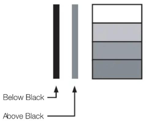
Figure 4-3. Typical PLUGE Pattern for Adjusting Brightness
PLUGE patterns vary but generally consist of some combination of black, white and gray areas against a black background. The example above includes two vertical bars and four shaded boxes.
Select Brightness from the Main menu. Use the ◀ or ▶ buttons to adjust the level so that:
- The darkest black bars disappear into the background.
- The dark gray areas are barely visible.
- The lighter gray areas are clearly visible.
- The white areas are a comfortable level of true white.
- The image contains only black, gray and white (no color).
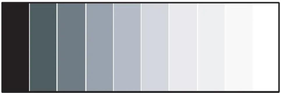
Contrast: On your external test pattern source, select a stepped, gray-bar pattern like the one shown in Figure 4-4.
natural_image
Gradient color bar transitioning from dark to white (no text or symbols)Figure 4-4. Typical Gray Bar Pattern for Adjusting Contrast
Select Contrast from the Main menu. Use the ◀ or ▶ buttons to adjust the contrast up until the top two bars become almost the same brightness, then down just until the brightness change between these bars is consistent with the other bars.

Note
Brightness and Contrast controls are interactive. A change to one may require a subtle change to the other in order to achieve the optimum setting.
Color Saturation: To adjust the overall color intensity, select Color Saturation from the Main menu. Decrease this setting if colors are overly saturated; increase it if colors appear muted or washed out.
Color Tint: Tint or "hue" is the ratio of red to green in the color portion of the image. To adjust the tint, select Color Tint from the Main menu. Decrease this setting to shift the hue toward red; increase it to shift the hue toward green.

Note
Like the Brightness and Contrast controls, the color and tint controls are interactive. A change to one may require a subtle change to the other in order to achieve the optimum setting.
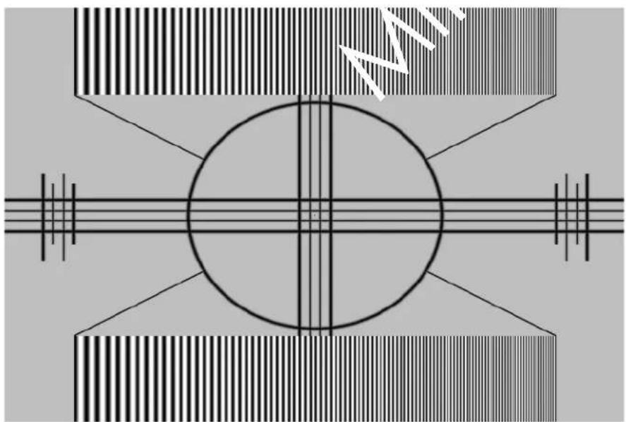
Sharpness: "Sharpness" is the amount of high-frequency detail in the image. To adjust this, select Sharpness from the Main menu and press ENTER. On your external test pattern source, select a pattern like the one shown in Figure 4-5.
natural_image
Symmetrical abstract diagram with concentric circles and diagonal lines, no text or symbols presentFigure 4-5. Typical Test Pattern for Adjusting Sharpness
- Sharpness (Simple Mode): Adjust as needed, looking for white edges around the transitions from black to gray and differently-sized lines in the "sweep" patterns at the top and bottom. Lower the sharpness setting to eliminate them.
- Sharpness Mode: Sharpness Mode allows or prevents access to the detailed sharpness controls in this menu.
In most cases, Simple mode provides a sufficient level of control to produce the best picture from the most popular sources. In Simple mode, only the Sharpness (top-most) slider is adjustable; the others are grayed out.
Choose Advanced mode if you need more precise control over sharpness. In Advanced mode, only the top slider is grayed out.
- Horizontal Sharpness / Vertical Sharpness / Diagonal Sharpness: Use these controls to enhance image detail along horizontal, vertical and diagonal edges respectively.
- Sharpness Overshoot: Use the Sharpness Overshoot control to minimize or eliminate rings or shadows on dominant edges that cannot be removed using the "simple" Sharpness control.
• Horizontal Texture / Vertical Texture / Diagonal Texture / Texture Overshoot:
Use these controls to remove artifacts from textured areas that cannot be removed using the "simple" Sharpness control.
- Noise Threshold: The Noise Threshold setting adjusts the frequency below which the Sharpness controls have an effect. Frequencies above the threshold are considered "noise."
Generally, the higher the setting, the more noticeable the effect of any adjustments will be.
Noise Reduction: To apply noise reduction to the source signal, select Noise Reduction from the Main menu and press ENTER. Noise Reduction is useful for clearing up noisy images from interlaced SD sources.
- Noise Reduction (Simple Mode): Use the ◀ or ▶ button to adjust as desired, keeping in mind that reducing noise (which reduces high frequencies) may also soften the image.
- Noise Reduction Mode: Noise Reduction Mode allows or prevents access to the detailed noise reduction controls in this menu.
In most cases, Simple mode provides a sufficient level of control to produce the best picture from the most popular sources. In Simple mode, only the Noise Reduction (top-most) slider is adjustable; the others are grayed out.
Choose Advanced mode if you need more precise control over noise reduction. In Advanced mode, only the top slider is grayed out.
- General Noise Reduction: General Noise Reduction is temporal and spatial noise reduction for all types of inputs. The scene is analyzed for differences from frame to frame and reduces those differences that are not determined to be motion.
- Block Artifact Reduction: Use this control to reduce or eliminate so-called "block artifacts" in MPEG-compressed video signals (digital broadcasts or DVDs). Set it as needed to minimize distortion within horizontal and vertical block boundaries.
- Mosquito Noise Reduction: Use this control to reduce or eliminate so-called "mosquito noise" in MPEG-compressed video signals. Set it as needed to minimize distortion around the edges of moving objects, moving artifacts around edges and/or blotchy noise patterns superimposed over the objects.
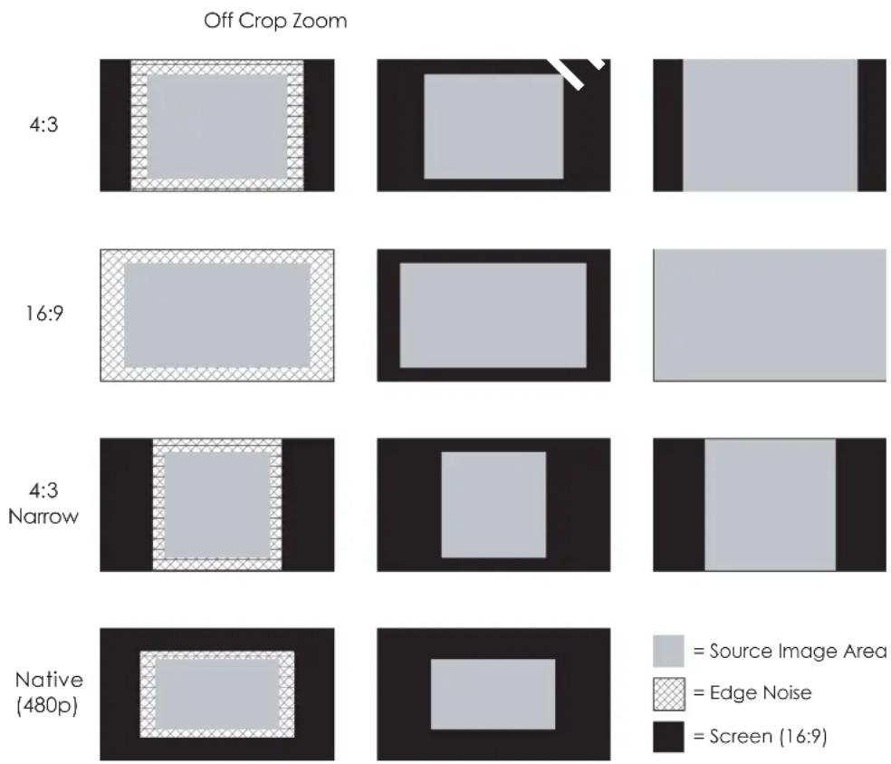
Overscan: Some television programs are produced based on the assumption that older television sets may not display the outer edges of the broadcast picture area. Overscan effectively hides these inactive, outer edges of the image. Choose one of the following:
- Off: This setting leaves the image as-is.
- Crop: This setting adds a mask at the left and right edges of the source active image equal to 3% of the displayed horizontal resolution, and at the top and bottom edges equal to 3% of the displayed vertical resolution.
- Zoom: This setting adds a factor to the scaling of the source active image so that the vertical and horizontal resolutions are 106% of the size determined by the aspect ratio function. Anything outside of the original image area is removed.

Note
When the Aspect Ratio is set to Native, set Overscan to Off or Crop.
Figure 4-6 illustrates the effect of each overscan setting for each aspect ratio.
heatmap
| Crop Ratio | Method | Off Crop Zoom | Off Crop Zoom | Off Crop Zoom | Off Crop Zoom | Off Crop Zoom | Off Crop Zoom | |------------|-----------------|---------------|---------------|---------------|---------------|---------------|---------------| | 4:3 | Source Image Area | High | High | Medium | Low | Low | Low | | 4:3 | Edge Noise | Medium | Medium | Low | Low | Low | Low | | 4:3 | Screen (16:9) | Low | Low | Low | Low | Low | Low | | 16:9 | Source Image Area | High | High | Medium | Low | Low | Low | | 16:9 | Edge Noise | Medium | Medium | Low | Low | Low | Low | | 16:9 | Screen (16:9) | Low | Low | Low | Low | Low | Low | | 4:3 Narrow | Source Image Area | High | High | Medium | Low | Low | Low | | 4:3 Narrow | Edge Noise | Medium | Medium | Low | Low | Low | Low | | 4:3 Narrow | Screen (16:9) | Low | Low | Low | Low | Low | Low | | Native (480p) | Source Image Area | High | High | Medium | Low | Low | Low | | Native (480p) | Edge Noise | Medium | Medium | Low | Low | Low | Low | | Native (480p) | Screen (16:9) | Low | Low | Low | Low | Low | Low |Figure 4-6. Overscan Examples
Source Select: To select a video source, press ▲ or ▼ to highlight Source Select, then press ENTER. This displays the Source Select sub-menu, shown in Figure 4-7.
The default source selection is HDMI 1. All sources that are not available per the source enable function (refer to Source Enable on page 56) are grayed out.
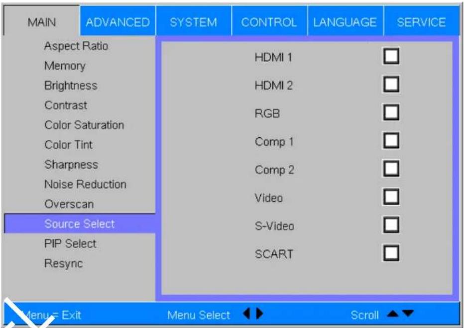
Figure 4-7. Source Select Sub-Menu
PIP Select: To select a PIP (secondary) video source, press ▲ or ▼ to highlight PIP Select, then press ENTER. The default PIP selection is Off.
All sources that are not available per the source enable function (refer to Source Enable on page 56) are grayed out.
All sources that cannot be used for PIP due to a shared electronic path with the Active source are grayed out. The PIP source is a saved setting for each source, like brightness and contrast.
If for some reason the current PIP source becomes invalid (by disabling it in the source enable menu, for instance), PIP Select automatically resets to Off.
Resync: If the projected image becomes unstable or degraded, press ▲ or ▼ to highlight Resync, then press ENTER. This causes a re-acquisition of the active source and the PIP source, if present. It also changes any Fine Sync settings (described on page 53) for this timing to the default setting.
Use the controls in the Advanced menu, shown in Figure 4-8, to perform advanced image adjustments.
Advanced
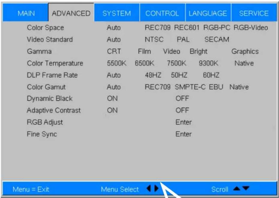
Figure 4-8. PD7170 Advanced Menu
Color Space: Select Color Space from the Advanced menu to choose the color space of the source signal for HDMI, RGB, and component connections.
- The default setting, Auto, functions as follows:
- HDMI: If the Auxiliary Video Information (AVI) infoframe contains color space and/or range data, the PD7170 uses that information. Otherwise, for RGB sources, the PD7170 uses the RGB-Video color space. For component SDTV and EDTV resolutions, REC601 is used. For other component video resolutions, REC709 is used.
- RGB: If Hsync or Vsync signals are present, the PD7170 uses the RGB-PC color space. Otherwise, REC601 is used for SDTV and EDTV sources, and REC709 for all other sources.
- Component: For SDTV and EDTV resolutions, the PD7170 uses the REC601 color space. For all other resolutions REC709 is used.
In most cases, the Auto setting determines the correct color space to use. If it does not, you can force the PD7170 to use a specific color space. Choose one of the following:
- REC709 sets the color space matrix to that defined in ITU-R BT.709.
- REC601 sets the color space matrix to that defined in ITU-R BT.601.
- RGB-PC uses RGB color space and sets black at 0,0,0 RGB and white at 255,255,255 RGB, assuming an 8-bit image.
- RGB-Video uses RGB color space and sets black at 16,16,16 RGB and white at 235,235,235, assuming an 8-bit image, to correspond to the luminance values defined in digital component standards.
Video Standard: Select Video Standard from the Advanced menu to specify the color system for composite video or S-Video input signals.
Different countries use different formats for video signals. Select the appropriate Video Standard for your region:
- Auto: The color systems are automatically identified and the format is set accordingly.
- P A L : This is the standard used in Europe, Australia and many other parts of the world, typically with a 50Hz frame rate.
- S E C A M : This is a standard format used mainly in France and Russia.
- NTSC: This is the standard format used mainly in the United States and Japan.
Gamma: Select Gamma from the Advanced menu to choose a DLP de-gamma curve. Used correctly, the Gamma control can improve contrast while maintaining good details for blacks and whites.
If excess ambient light washes out the image and it becomes difficult or impossible to see details in dark areas, lower the gamma setting to compensate. This improves contrast while maintaining good details for blacks. Conversely, if the image is washed out and unnatural, with excessive detail in black areas, increase the setting.
- CRT sets the gamma to 2.5.
• Film sets the gamma to 2.2. - Video is similar to Film gamma but differs in dark areas of the image to correspond to the function that video cameras use to create images.
• Bright sets the gamma to 2.0. - Graphics should only be used for computer presentations that require increased brightness at the cost of grayscale accuracy.
Color Temperature: Color temperature defines the "color of gray;" that is, adjusts the 75% white point to various color points.
To choose a color temperature setting, select Color Temperature from the Advanced menu. Then, press ◀ or ▶ to select 5500K, 6500K, 7500K, 9300K or Native. The default setting, 6500K, is appropriate for most situations. Higher settings produce a "bluer" picture; lower ones impart a reddish hue to the image. Select Native to disable white point adjustment of the source signal.
DLP Frame Rate: Select DLP Frame Rate from the Advanced menu to choose the output frame rate. You can have the PD7170 automatically determine the optimum frame rate, or you can force it to use a specific frame rate.

Note
If PIP is active, the PD7170 converts the PIP source frame rate to the same frame rate as the main source.
- The default setting, Auto, frame locks to the main source if it has a vertical refresh rate of between 48 and 62Hz. Vertical refresh rates of from 24 to 31Hz are doubled. Frame rates between 31 and 48Hz and greater than 62Hz are converted to 60Hz.
- Select 48Hz to force the output frame rate to 48Hz. Use this setting to eliminate 2:3 pull-down judder with 60Hz film-based sources.
- 50Hz and 60Hz force the output frame rate to 50Hz and 60Hz respectively.
Color Gamut: Select Color Gamut from the Advanced menu to select a color gamut (range) that may be different from the default color gamut.
Each setting defines the precise hue of each primary (red, green and blue) and secondary (yellow, cyan and magenta) color component used to generate the millions of colors produced in displays. Changing either or both of these numbers changes the hue of the color and relocates the “triangle” for possible colors. For example, changing the x/y coordinates for red moves the color closer to either orange or violet, which in turn affects all displayed colors having a red component.
- Auto automatically chooses the appropriate color gamut:
- SMPTE C for NTSC, 480i and 480p sources.
- EBU for PAL, SECAM, 576i and 576p sources.
• REC709 for all other sources.
• REC709 chooses the REC709 color gamut.
- Select SMPTE-C to choose the SMPTE-C color gamut.
- Select EBU to choose the EBU color gamut.
- Select Native to use REC709 for cyan, magenta, and yellow and uncorrected values for red, green, and blue.
Table 4-3 lists the x- and y-coordinates for each primary and secondary color component.
Table 4-3. x/y Color Gamut Values
| Primary Color | Color Gamut Settings and Associated x/y Values | |||||
| REC709 SMPTE “C” EBU | ||||||
| x y x y | x y | |||||
| Red 0.640 0.3 | 30 0.635 0.3 | 40 0.640 0.330 | ||||
| Yellow 0.419 | 0.505 0.421 | 0.506 0.418 0.502 | ||||
| Green 0.300 | 0.600 0.305 0 | 0.595 0.290 0.600 | ||||
| Cyan 0.225 0Blue 0.150 0.060 0.155 0.070 0.150 0.060 | 0.329 0.228 0 | 326 0.220 0.329 | ||||
| Magenta 0.321 0.154 0.380.162 0.328 0.158 | ||||||
DynamicBlack: Select DynamicBlack from the Advanced menu to enable (On) or disable (Off) the DynamicBlack actuator in the optical engine. DynamicBlack uses a dynamic iris that modulates light to the DMD based on the actual content of the video material. Planar recommends that you disable DynamicBlack before adjusting Brightness, Contrast or other image settings.
Adaptive Contrast: Adaptive Contrast enhancement expands the light and dark portions of an output image according to the mean luminance of the input image.
RGB Adjust: To remove any trace of color from the white areas of the projected image, choose RGB Adjust from the Advanced menu and press ENTER. This displays the RGB Adjust sub-menu, shown in Figure 4-9.
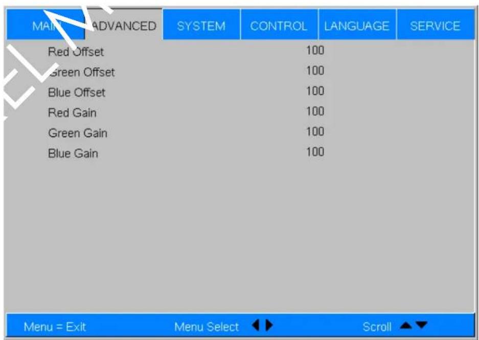
Figure 4-9. RGB Adjust Sub-Menu
- Gain: Use the Gain controls to correct color imbalances in the bright areas of the image. A good way to do this is to use a test pattern consisting mostly of solid white areas, such as an 80 IRE "window" pattern. If the white areas contain traces of red, green or blue, decrease the Gain for that color.
- Offset: Use the Offset controls in the RGB Adjust sub-menu to correct color imbalances in the dark areas of the image. A good way to do this is to use a test pattern consisting mostly of dark gray areas, such as a 30 IRE "window" pattern. If the gray areas contain traces of red, green or blue, decrease the Offset for that color.
The Gain controls increase or decrease the full-scale input range; the Offset controls shift the entire range, resulting in a change in brightness.

Note
Generally, higher Gain settings reduce the image contrast; higher Offset settings reduce the image brightness.
Fine Sync: To fine-tune the position and other image attributes, choose Fine Sync from the Advanced menu and press ENTER. This displays the Fine Sync sub-menu, shown in Figure 4-10.
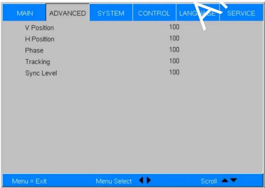
Figure 4-10. Fine Sync Sub-Menu
- V Position: This control adjusts the vertical position of the image within the designated image area, up to 25 per cent of the image height up or down.
- H Position: This control adjusts the horizontal position of the image within the designated image area, up to 25 per cent of the image width left or right.
- Phase (RGB or Component sources): This control adjusts the phase of the pixel sampling clock relative to the incoming signal. Adjust the phase when an RGB or Component image still shows shimmer or "noise" after Tracking has been optimized.

Tip
Adjust the Phase after adjusting Tracking (see below). If some shimmer from a video or HDTV source persists, use the Noise Reduction controls (described on page 46) to remove high-frequency noise from the signal.
For best results, use a good test pattern such as a smooth gray consisting of a clear pattern of black and white pixels, or a similar "half on, half off" graphic image. Adjust the slidebar until the image stabilizes and each pixel is clearly defined. You may notice that you can stabilize the image at more than one point. Use either setting in such cases.
- Tracking (RGB or Component sources): Tracking determines the frequency of the pixel sampling clock, indicated by the number of incoming pixels per line, so that all pixels generated by a particular source are sampled.
Steady flickering or several soft vertical stripes or bands across the entire image indicates poor pixel tracking. Proper pixel tracking helps ensure that the image quality is consistent across the screen, that aspect ratio is maintained and that pixel phase (see above) can be optimized.
- Sync Level (Component sources only): Select Sync Level to adjust the voltage level of the PD7170 Sync signal detection circuitry.
Sync Level adjustment is occasionally necessary when a DVD player or HDTV source signal drops “below black” (for example, during scenes with explosions or when subtitles are present) and causes the projector to temporarily lose sync. If the Sync Level from the source is persistently too low, the projector won’t sync with the source at all.
The range is from 50 to 256 millivolts (mV) inclusive. The default setting is 240 mV and should rarely require adjustment.
Use the controls in the System menu, shown in Figure 4-11, to adjust the lamp, change the display orientation and perform other, common installation tasks.
← System
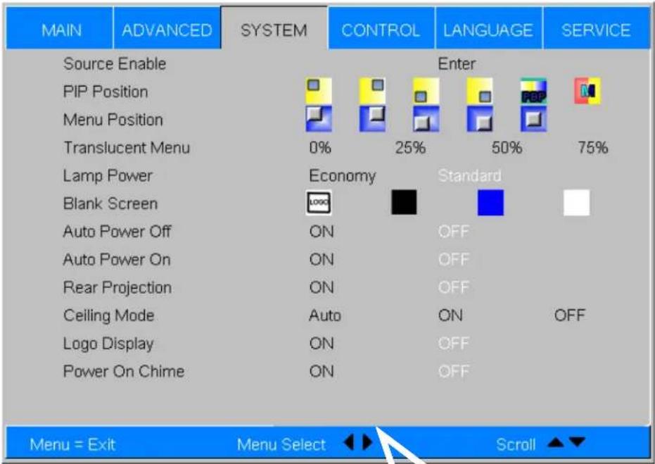
Figure 4-11. PD7170 System Menu
Source Enable: To enable or disable selection of a source, choose Source Enable from the System menu and press ENTER. This displays the Source Enable sub-menu, shown in Figure 4-12.
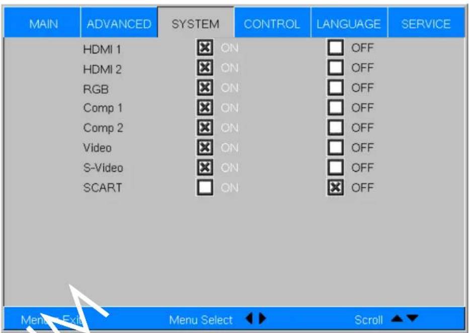
Figure 4-12. Source Enable Sub-Menu
- HDMI 1/HDMI 2: Enables or disables the HDMI 1 and HDMI 2 sources.
- RGB: Enables or disables the RGB source.
- Comp 1/Comp 2: Enables or disables the Component 1 and Component 2 sources.
• Video: Enables or disables the Composite video source.

Note
If either Component 1 or Video is enabled, SCART must be disabled.
- S-Video: Enables or disables the S-Video source.
- SCART: Enables or disables the SCART RGBS source.

Note
If SCART is enabled, both Component 1 and Video must be disabled.
PIP Position: To change the position of the PIP image, choose PIP Position from the System menu; see Figure 4-13. Choose one of the following:
- Top Left: This places the PIP source into a 427x240 designated image area at the top left of the screen.
- Top Right: This places the PIP source into a 427x240 designated image area at the top right of the screen.
- Bottom Left: This places the PIP source into a 427x240 designated image area at the bottom left of the screen-safe area of the DMD.
- Bottom Right: This places the PIP source into a 427x240 designated image area at the bottom right of the screen-safe area of the DMD.
- Picture-By-Picture: This reduces the designated image area of the Active source to 614x345 and places it next to the PIP source, which is also in a 614x345 image area. These two images are centered on the screen.
- Split Screen: This is a special mode in which the active source is also used as the PIP source and placed in a PIP area equal to half the display on the left side. This results in the right half of the image being the active source and the left half is the PIP source. The PD7170 applies the User Memory 2 settings to the PIP image.
Split-screen mode is useful for viewing "before" and "after" settings for Sharpness, Noise Reduction and other advanced image parameters. See Figure 4-14.
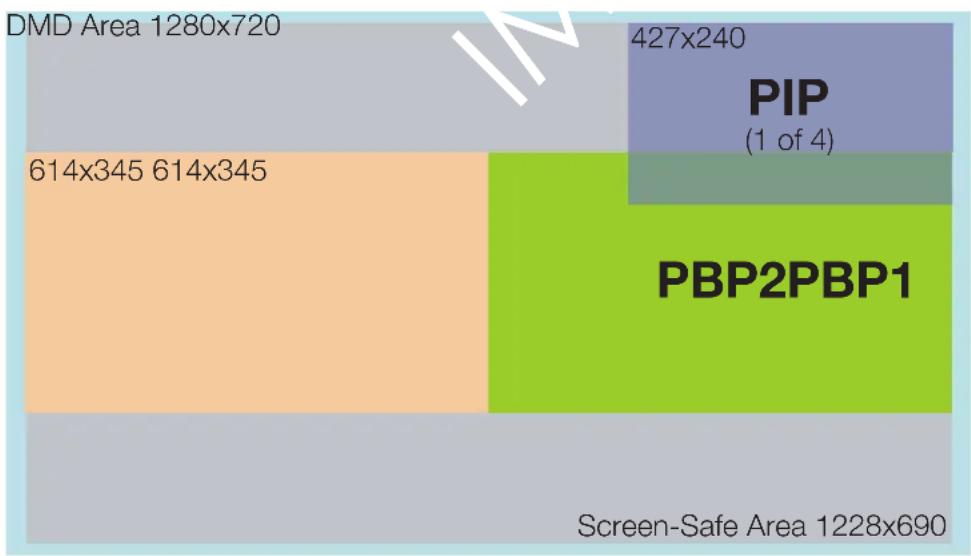
treemap
| Category | Value | | ------------------ | --------- | | DMD Area | 1280x720 | | PBP2PBP1 | 427x240 | | Screen-Safe | 1228x690 | | PIP (1 of 4) | 1 |Figure 4-13. PIP and PBP areas for 720p Display
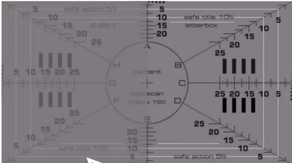
Figure 4-14. PIP Split-Screen Mode
Menu Position: Select Menu Position from the System menu to change the OSD menu position. The default setting is “”(top left).
Translucent Menu: Select Translucent Menu from the System menu to adjust the degree of translucence (show-through) in the menus and message boxes. 0% means that the menus are opaque. The default setting is 25%.
Lamp Power: Select Lamp Power from the System menu to adjust the lamp output level. You can choose to run the lamp as bright as possible (260W) or you can choose the default, Economy (230W) setting. Generally, lower lamp output prolongs the life of the lamp, but decreases brightness. This setting is per source, not global, so it can be saved like other user settings.
Blank Screen: Select Blank Screen from the System menu to choose the color of the blank screen that appears when no source signal is present. The options are Logo, Black, Blue and White. The default is Black.
Auto Power Off: Set Auto Power Off to On to have the PD7170 turn itself off after 20 minutes of inactivity (no source signal present).
Auto Power On: Setting Auto Power On to On causes the projector to automatically power up when AC power is present. If the projector is plugged into a switched AC outlet, this allows the projector to be turned on using a wall switch instead of the remote control unit. If you do not need this capability, set Auto Power On to Off (this is the default setting).
Rear Projection: This control reverses all images and menus, and is necessary when the projector is used in rear-projection applications. The default is Off.
Ceiling Mode: This control flips the image so the projector can be used in ceiling mounted installations. The default setting, Auto, automatically determines the orientation using an internal sensor.
Logo Display: This controls whether or not the Planar logo appears during startup.
Power On Chime: This controls the audible chime at startup.
the projector.
◀ ControlSelect Control from the Mc
| MAIN | ADVANCED | SYSTEM | CONTROL | LANGUAGE | SERVICE |
| Lens Control | Focus | Zoom | Lens Shift | ||
| 1 Key | Enter | ||||
| 2 Key | Enter | ||||
| 3 Key | Enter | ||||
| 4 Key | Enter | ||||
| 5 Key | Enter | ||||
| M1 Key | User-1 | User-2 | ISF-Day ISF-Night | ||
| M2 Key | User-1 | User-2 | ISF-Day ISF-Night | ||
| M3 Key | User-1 | User-2 | ISF-Day ISF-Night | ||
| Trigger-1 | Lamp 16:9 | Letterbox 4:3 | 4:3-Narrow RS232 | ||
| Trigger-2 | Lamp 16:9 | Letterbox 4:3 | 4:3-Narrow RS232 | ||
| Change Remote Code | Enter | ||||
| Auto Source | ON | OFF | |||
| Menu = Exit Menu Select Scroll ▲▼ | |||||
Figure 4-15. PD7170 Control Menu
Lens Control: Select Lens Control from the Control menu to perform lens adjustments (focus, zoom and lens shift). For detailed instructions, refer to Lens Adjustments on page 31.
1 Key / 2 Key / 3 Key / 4 Key / 5 Key: These menu items assign the function of the keys numbered 1 through 5 on the remote.
There are eight sources corresponding to the eight connections to the projector. When you assign a source to a numbered key, the projector immediately goes to that source when the key assigned to it is pressed.
If the chosen source is disabled via the Source Enable menu (refer to page 56), this setting has no effect.
M1 Key / M2 Key / M3 Key: These menu items assign which memory setting to recall when the M1, M2 or M3 key on the remote is pressed.
Trigger 1: Select Trigger 1 from the Control menu to specify when the Trigger 1 port outputs 12 volts. There is a three-second delay before activation to prevent operation while selecting an aspect ratio.
- Lamp causes the port to output 12 volts whenever the lamp is on.
- 16:9 causes the port to output 12 volts whenever the 16:9 aspect ratio is chosen.
- Letterbox causes the port to output 12 volts whenever the Letterbox aspect ratio is chosen. The output stops if PIP is enabled (PIP source is set to anything other than off).
- 4:3 causes the port to output 12 volts whenever the 4:3 aspect ratio is chosen. The output stops if PIP is enabled (PIP source is set to anything other than off).
- 4:3 Narrow causes the port to output 12 volts whenever the 4:3 Narrow aspect ratio is chosen. The output stops if PIP is enabled (that is, the PIP source is set to anything other than off).
- RS232 causes the port to output 12 volts when an RS232 screen trigger 1 "on" command is received and stop when a trigger 1 "off" command is received. The 12 volt output also stops when the projector is turned off.
Trigger 2: Select Trigger 2 from the Control menu to configure the Trigger 2 output. Trigger 2 operates identically to Trigger 1.
Change Remote Code: To change the remote IR code set to which the PD7170 responds, select Change Remote Code from the Control menu and press ENTER. A "Change Remote Code Set?" message box appears. Select Yes to confirm the code set change.
You may need to change the code set if other equipment in the theater responds to commands from the PD7170 remote control in ways that are unexpected or undesirable.
When you select a different remote code set on the PD7170, you must re-program the remote control unit to use that same code set. To do this, press and hold the LIGHT and ENTER buttons simultaneously for approximately five seconds. When the code set has changed, the remote control back-lighting "blinks" to visually confirm the change.
Table 6-1 lists the IR codes associated with each remote control button.
Auto Source: This control chooses whether or not to scan for other active sources if the current source is not available. The default setting is Off.
Select Language from the Main Menu to change the OSD Language.
The PD7170 can display the menus in English, French, German, Italian, Spanish, Swedish, Traditional Chinese, Simplified Chinese, Japanese, Korean, Portuguese or Russian.
Language
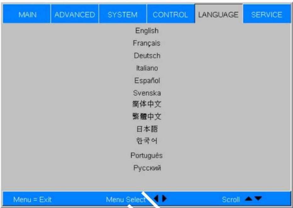
Press ▲ or ▼ to select a language. Then, press ENTER to confirm your selection.
Service Access the Service Menu, shown in Figure 4-16, to view information that uniquely identifies your projector and indicates its current operational status:
- Model Name
- Unit Serial Number
- Software Version
• Active/PIP Source - Pixel Clock
- Signal Format
• H/V Refresh Rate
- Lamp Hours (number of lamp hours elapsed since the last reset)
Should you ever need to contact Planar Technical Support, this information will help them answer your questions and/or resolve product performance issues.
| MAIN | ADVANCED | SYSTEM | CONTROL | LANGUAGE | SERVICE |
| MODEL NAME : | PD7170 | ||||
| Serial Number : | SN-12345678900000 | ||||
| Software Version : | HT8610PXCA-MMD01.1109 | ||||
| Active/PIP source : | HDMI 1 / OFF | ||||
| Pixel Clock : | 148.5MHZ | ||||
| Signal Format : | 1080P | ||||
| H/V Refresh Rate : | H:67.5KHZ, V:60.00HZ | ||||
| Lamp Hours : | 9999999999HR | ||||
| Lamp Hour Reset | Enter | ||||
| Factory Reset | Enter | ||||
| Blue Only | ON | OFF | |||
| Test Patterns | ON | OFF | |||
| Altitude | Auto | High | |||
| Menu = Exit | Menu Select | ◀ ▶ | Scroll ▲▼ | ||
Figure 4-16. PD7170 Service Menu
You can also perform various maintenance tasks, such as resetting the lamp hour counter, from this menu.
Lamp Hour Reset: When you replace the projector lamp (refer to Lamp
Replacement on page 65), you should also reset the lamp hour counter. To do this, select Lamp Hour Reset from the Service menu, then press ENTER. Press
ENTER again to confirm the reset. Or, to cancel the operation, press ▶ on the remote to highlight No, then press ENTER.

Note
Reset the Lamp Hour counter ONLY after you replace the lamp. Otherwise, the reported "Lamp Hours" will be inaccurate.

WARNING
Do not exceed the recommended lamp life. An old lamp becomes increasingly fragile and prone to sudden failure.
Factory Reset: Select Factory Reset from the Service menu to restore all projector settings – except those listed below – to their factory-default values:
- Lamp Hours
- User Memory 1 / User Memory 2
• IS F Day
• ISF Night - Model Name / Serial Number
- Language
Blue Only: This feature removes all red and green color information from the image, and is useful for color-calibrating the projector or other video components.
Test Patterns: The PD7170 has numerous internal test patterns that are useful to technicians for advanced calibration, measurement and fault isolation purposes. To access them, select Test Patterns from the Service menu and set it to On.
The available test patterns are:
- White
- Black
- Red
- Green
- Blue
• C y a n - Magenta
- Yellow
• ANSI Checkerboard
• Horizontal Gray Ramp - Focus Grid
Press ◀ or ▶ on the remote control unit or built-in keypad to cycle through the test patterns.

Note
The OSD menus are not available when in "test pattern" mode.
To turn test patterns off, press any key other than ◀ or ▶ on the remote control unit or built-in keypad.
Altitude: Select Altitude from the Service Menu to control the operation of the projector's cooling fan.
In most cases, the default setting (Auto) will maintain the correct operating temperature. If the lamp frequently turns off due to overheating, or in certain high-altitude operating environments, you may need to change this setting to High.
Maintenance and Troubleshooting
The lamp should be replaced when it reaches the end of its life (typically between 2000 and 2500 hours depending on the Lamp Power setting), or sooner if a noticeable degradation in brightness occurs. Contact your Planar dealer to obtain a replacement lamp.
- Turn off the projector and unplug the power cord. Allow the projector to cool down for approximately 60 minutes prior to removing the lamp assembly for replacement.
- Using a flat-blade screwdriver, loosen the four screws holding the rear compartment cover in place.
- Remove the rear compartment cover by tilting it upward.
- Loosen the screw on the lamp cover and pull the lamp cover out.
- Loosen the two screws on the lamp module.
- Pull the lamp module handle firmly to remove the lamp module.
- Perform Steps 6 through 2 (in reverse order) to install the new lamp module.
- Turn on the power and reset the lamp timer.
5.1 Lamp Replacement
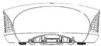
natural_image
Technical line drawing of a stadium or stadium structure with arches and seating (no text or symbols)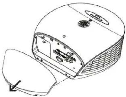
natural_image
Line drawing of a device with internal components and a highlighted section (no text or symbols)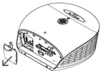
natural_image
Technical line drawing of a mechanical device with internal components and mounting bracket (no text or symbols)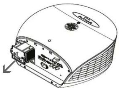
natural_image
Technical line drawing of a mechanical device with internal components and a directional arrow (no text or symbols)5.2
Troubleshooting Tips
Table 5-1 provides some general guidelines for troubleshooting problems you may encounter with the PD7170. If the suggested solutions fail to resolve the problem or if you encounter an issue not described here, please contact Planar Technical Support.
Table 5-1. Troubleshooting Chart
Symptom Possible Cause(s) Solution
| The projector does not turn on. | The PD7170 is not plugged in or the AC outlet is not active.Lamp cover is securely attached. | Ensure that the PD7170 is plugged in and that the AC outlet is active.Securely attach the lamp cover. |
| The projector does not turn back on after it was powered off. | The projector will not turn on for two minutes after power-off, to protect the lamp. | Wait until the PD7170 completes its cool-down (POWER LED lights solid green). |
| The remote control does not work correctly. | The batteries have run out.IR code set mismatch between remote control unit and projector. | Replace the batteries.Press and hold the LIGHT and ENTER remote control buttons simultaneously until the remote control back-lighting “blinks” (approximately five seconds). Then, try again. |
| The projector is on and OSD menus appear, but there is no video image on-screen. | Incorrect source selection.Source component is not turned on.Source component is connected incorrectly or not at all. | Select the correct source.Turn on the source.Check cable connection from source component to projector. |
| A projected image from a DVD is split or otherwise scrambled. | DVD player is connected to the Component input and set to progressive scan mode. | Turn off progressive scan on the DVD player. |
| Image is blurred. • The lens is not correctly focused. | Adjust the focus with the remote control. | |
| Image is too bright and/or lacks definition in the bright areas of the image. | Contrast is set too high. | Lower the contrast setting. |
| Image appears “washed out” and/or dark areas appear too bright. | Brightness is set too high. | Lower the brightness setting. |
| Colors in the image are swapped; for example, reds appear blue or vice versa. | The Red/Pr, Green/Y or Blue/Pb outputs from the source are connected to the wrong inputs on the PD7170. | Ensure that the source outputs are connected to the correct PD7170 input. |
| LED is flashing alternating green and red. | The lamp cover is open.The lamp has failed or exceeded its usage life. | Close the lamp cover.Replace the lamp with a new one. |
| LED is flashing red. • PD7170 internal temperature is too high. | Power off the PD7170 and allow it to cool down. Ensure that the intake and exhaust vents are not blocked.Turn the projector back on. If the problem persists, please contact Planar Technical Support for assistance. | |
LED lights solid red. • Fans are not work • Please contact Planar properly or power-on technical Support for self-test has failed. assistance.
Notes:
Serial Communications
To interface the PD7170 with a home theater automation/control system or a PC running terminal emulation software:
- Connect it to your control system or PC as shown in Figure 3-11.
- Start a terminal session on your PC using a terminal-emulation program, such as HyperTerminal.
- Configure the RS-232 controller or PC serial port as follows: 38400 bps, no parity, 8 data bits, 1 stop bit and no flow control.
- Type ky or op followed by a command from among those listed in Table 6-1 or Table 6-2 and press
. For example, to change the aspect ratio to Letterbox, type op aspect = 1 .
Serial commands to the PD7170 take the following form:
- Commands are in ASCII format.
- Spaces and tabs can be used to improve readability and are ignored by the projector.
- All commands must end with a carriage return (ASCII hex 0D) to signify that the projector can now read and execute the command.
- Commands are not case-sensitive.
The PD7170 supports two types of commands: key commands and operation commands. Key commands mimic pressing a button on the remote control. Operation commands tell the projector exactly what to do.
All commands start with 2 letters:
ky for key commands.
op for operations commands.
6.1
RS-232 Connection and Port Configuration
6.2
Serial Command Syntax
◀ Key CommandsThe syntax for key
ky
Some key command examples:
ky menu[CR]
Bring up or cancel menu display.
ky mem.sw[CR] Switch to next user memory.
ky asp.16.9[CR] Apply 16:9 aspect ratio.
The response from the projector for key commands will be the same command in UPPERCASE.
Input: ky mem.sw[CR]
Response: KY MEM.SW [CR]
Table 6-1 lists the serial command key names and IR codes.
Table 6-1. Serial Command Key Names and IR Codes
| RS232 Keyname | Remote Button | IR Code | Description | |
| Set 1 | Set 2 | |||
| pow.on |  | 0x01 | 0xB7 Turn | power on. |
| src.sw | (none) 0x02 | 0xB8 Switch to the next source. | ||
| pow.off |  | 0x09 | 0xB9 Turn | power off. |
| menu |  | 0x15 | 0xB A Bring | up or cancel menu display. |
| enter |  | 0x17 | 0xB B Keypad enter. | |
| cur.down |  | 0x18 | 0xBC Keypad down arrow. | |
| cur.up |  | 0x1A | 0xBD Keypad up arrow. | |
| cur.left |  | 0x1D | 0xBE Keypad left arrow. | |
| cur.righ |  | 0x1F | 0xB F Keypad right arrow. | |
| bright |  | 0x80 | 0xC0 Bring | up or cancel brightness slider. |
| contrast |  | 0x81 | 0xC1 Bring | up or cancel contrast slider. |
| sharp |  | 0x82 | 0xC2 Bring | up or cancel sharpness slider. |
| nr |  | 0x83 | 0xC3 Bring | up or cancel noise reduction slider. |
| resync |  | 0x84 | 0xC4 | Force reacquisition of active and PIP source |
| gam.sw |  | 0x85 | 0xC5 Switch to the next gamma. | |
| gam.crt | (none) 0x86 | 0xC6 Switch to CRT gamma. | ||
| gam.film | (none) 0x87 | 0xC7 Switch to Film gamma. | ||
| gam.vide | (none) 0x88 | 0xC8 Switch to Video gamma. | ||
| gam.brig | (none) | 0x89 | 0xC9 | Switch to Bright Room gamma. |
| gam.pc | (none) 0x8A | 0xCA | Switch to | PC gamma. |
| src.1 |  | 0x8B 0x | CB Switch | the active source to source 1. |
| src.2 |  | 0x8C 0x | CC Switch | the active source to source 2. |
| src.3 |  | 0x8D 0x | CD Switch | the active source to source 3. |
| src.4 |  | 0x8E 0x | CE Switch | the active source to source 4. |
| src.5 |  | 0x8F 0x | CF Switch | the active source to source 5. |
| bla.tog |  | 0x90 | 0xD0 | Toggles between blank screen and regular display. |
| bla.on |  0x91 0x91 | 0xD1 Turn blank | screen on. | |
| bla.off | (none) 0x92 | 0xD2 Turn blank | screen off. | |
| osc.sw | OS | 0x93 0xD3 Switch | to the next Overscan mode. | |
| osc.zoom |  | 0x94 0xD4 Switch to | Overscan Zoom. | |
| osc.crop |  | 0x95 0xD5 Switch to | Overscan Crop. | |
| osc.off |  | 0x96 0xD6 Switch to | Overscan Off. | |
| mem.sw | [101E] | 0x97 | 0xD7 | Switch to the next user memory. |
| mem.1 |  | 0x98 0xD8 Recall | user memory associated with the M1 key. | |
| mem.2 |  | 0x99 0xD9 Recall | user memory associated with the M2 key. | |
| mem.3 |  | 0x9A 0xDA Recall | user memory associated with the M3 key. | |
| isf.day |  | 0x9B | 0xDB | Recall ISF Day user memory. |
| isf.nigh |  | 0x9C | 0xDC | Recall ISF Night user memory. |
| asp.sw |  | 0x9D 0xDD Switch | to the next aspect ratio. | |
| asp.16.9 | (none) | 0x9E | 0xDE | Apply 16:9 aspect ratio to the active source. |
| asp.4.3 | (none) | 0x9F | 0xDF | Apply 4:3 aspect ratio to the active source. |
| asp.lett | (none) | 0xA0 | 0xE0 | Apply Letterbox aspect ratio to the active source. |
| asp.narr | (none) | 0xA1 | 0xE1 | Apply 4:3 Narrow aspect ratio to the active source. |
| pip.sw | PIP | 0xA3 | 0xE3 Switch | to next “PIP Select” state. |
| pip.1 | (none) | 0xA4 | 0xE4 | Change “PIP Select” to source 1. |
| pip.2 | (none) | 0xA5 | 0xE5 | Change “PIP Select” to source 2. |
| pip.3 | (none) | 0xA6 | 0xE6 | Change “PIP Select” to source 3. |
| pip.4 | (none) | 0xA7 | 0xE7 | Change “PIP Select” to source 4. |
| pip.5 | (none) | 0xA8 | 0xE8 | Change “PIP Select” to source 5. |
| pip.off | (none) | 0xA9 | 0xE9 | Change “PIP Select” to off. |
| pip.swap | SWAP | 0xAA | 0xEA Swap | the PIP image with the active source image. |
| pow.tog | (none) | 0xAC | 0xEC | Toggles between power on and power off. |
| lit.tog | LIGHT | 0xAD | 0xED Activ | vates remote backlighting only when pressed momentarily. When held for five seconds or more, the IR code for toggling the projector I/O panel light is transmitted. |
Operations Commands
Operations commands allow more flexible and direct control of the projector. The syntax for operations commands is as follows:
op
(Precede
The command type can be one of 5 functions:
| Operations Control Commands | ||
| Function Command Action on | unit | |
| Set | = | Makes the unit take that value. |
| Get | ? | Asks what the current value is. |
| Increment | + | Adds 1 to the current value. |
| Decrement | - | Subtracts 1 from the current value. |
| Execute | (none) | Performs an action such as a reset. |
Table 6-2 lists the valid operations commands. For all but Execute functions, the response from the projector is the command and “=
Some operations command examples:
Input: op bright ? [CR]
Response: OP BRIGHT = 100 [CR]
Input: op bright + [CR]
Response: OP BRIGHT = 101 [CR]
Input: op bright = 127 [CR]
Response: OP BRIGHT = 127 [CR]
Input: op bright - [CR]
Response: OP BRIGHT = 126 [CR]
Input: op resync [CR]
Response: OP RESYNC [CR]
Input: op sharp.mode = 1 [CR]
Response: OP SHARP.MODE = 1 [CR]
Input: op sharp.simple = 50 [CR]
Response: OP SHARP.SIMPLE = NA [CR]
Input: op sharp.simple ? [CR]
Response: OP SHARP.SIMPLE = NA [CR]
The last three commands show what happens when a control is grayed out. In this case, the sharpness mode was set to advanced (value = 1) and then the simple sharpness slider was attempted to be adjusted and queried. The response was "NA" or not available.
Table 6-2. Serial Commands
| OperationCommandsValues Notes | |||
| aspect = ? | 0 = 16:91 = Letterbox2 = 4:33 = 4:3 Narrow4 = Native | ||
| memory = ? | 0 = User Memory 11 = User Memory 22 = ISF Day3 = ISF Night4 = Default | ? only returns a value if ISF Day or ISF Night is active, otherwise it returns NA | |
| save.mem = | 0 = User Memory 11 = User Memory 2 | ||
| OperationCommandsValues Notes | |||
| save.isf = | 0 = ISF Day1 = ISF Night | ||
| bright = ? + | - | 0 - 200 | |
| contrast = ? | + - | 0 - 200 | |
| saturat = ? + | - | 0 - 200 | |
| tint = ? + - | 0 - 200 | ||
| sharp.simple = ? + - | 0 - 200 | ||
| sharp.mode = ? | 0 = Simple1 = Advanced | ||
| horiz.sharp = ? + - | 0 - 200 | ||
| vert.sharp = ? + - | 0 - 200 | ||
| diag.sharp = ? + - | 0 - 200 | ||
| sharp.over = ? + - | 0 - 200 | ||
| horiz.text = ? + - | 0 - 200 | ||
| vert.text = ? + - | 0 - 200 | ||
| diag.text = ? + - | 0 - 200 | ||
| text.over = ? + - | 0 - 200 | ||
| noise.thresh = ? + - | 0 - 200 | ||
| nr.simple = ? + - | 0 - 200 | ||
| nr.mode = ? | 0 = Simple1 = Advanced | ||
| nr.general = ? + - | 0 - 200 | ||
| block.reduct = ? + - | 0 - 200 | ||
| mosq.noise = ? + - | 0 - 200 | ||
| overscan = ?source.sel = | ? | 0 = Off1 = Crop2 = Zoom0 = HDMI 11 = HDMI 22 = RGB3 = YPrPb 14 = YPrPb 25 = S-Video6 = Video7 = SCART | |
| pip.select = | ? | 0 = Off1 = HDMI 12 = HDMI 23 = RGB4 = YPrPb 15 = YPrPb 26 = S-Video7 = Video8 = SCART | |
| resync (execute) | |||
| color.space = | ? | 0 = Auto1 = REC7092 = REC6013 = RGB-PC4 = RGB-Video | |
| video.stand = | ? | 0 = Auto1 = NTSC2 = PAL3 = SECAM | |
| gamma = ? | 0 = CRT1 = Film2 = Video3 = Bright4 = Graphics | ||
| color.temp = | ? | 0 = 5500K1 = 6500K2 = 7500K3 = 9300K | |
| dlp.frame = ? | 0 = Auto2 = 48 Hz3 = 50 Hz4 = 60 Hz | ||
| color.gamut =dbblack = ? | ? | 0 = Auto1 = REC7092 = SMPTE C3 = EBU4 = Native0 = Off1 = On | |
| focus + - | |||
| zoom + - | |||
| vert.offset + | - | ||
| horiz.offset | + - | ||
| red.off = ? + | - | 0-200 | |
| green.off = ? | + - | 0-200 | |
| blue.off = ? | + - | 0-200 | |
| red.gain = ? | + - | 0-200 | |
| green.gain = ? | + - | 0-200 | |
| blue.gain = ? | + - | 0-200 | |
| vert.pos = ? | + - | 0-200 | |
| horiz.pos = ? | + - | 0-200 | |
| phase = ? + - | 0-200 | ||
| tracking = ? | + - | 0-200 | |
| sync.level = ? | + - | 0-200 | |
| pip.pos = ? | 0 = Top left1 = Top right2 = Bottom left3 = Bottom right4 = Picture by picture5 = Split screen | ||
| lamp.pow = ? | 0 = Economy1 = Standard | ||
| menu.pos = ? | 0 = Top left1 = Top right2 = Bottom left3 = Bottom right4 = Center | ||
| trans.menu = ?blank.screen | = ? | 0 = 0%1 = 25%2 = 50%3 = 75%0 = Black1 = Blue2 = White3 = Logo | |
| auto.pow.off | = ? | 0 = Off1 = On | |
| auto.pow.on | = ? | 0 = Off1 = On | |
| rear.proj = ? | 0 = Off1 = On | ||
| ceil.mode = ? | 0 = Off1 = On2 = Auto | ||
| logo.disp = ? | 0 = Off1 = On | ||
| power.chime = | ? | 0 = Off1 = On | |
| 1.key2.key3.key4.key5.key | = ? | 0 = HDMI 11 = HDMI 22 = RGB3 = YPrPb 14 = YPrPb 25 = S-video6 = Video7 = SCART | |
| m1.keym2.keym3.key | = ? | 0 = User Memory 11 = User Memory 22 = ISF Day3 = ISF Night | |
| trig.1trig.2 | = ? | 0 = Lamp1 = 16:92 = Letterbox3 = 4:34 = 4:3 Narrow5 = RS232 | |
| remote.set = | ? | 0 = Set 11 = Set 2 | |
| auto.source = | ? | 0 = Off1 = On | |
| model.name | ? | ||
| ser.number | ? | ||
| soft.version | ? | ||
| act.sourcepip.source | ? | 0 = HDMI 11 = HDMI 22 = RGB3 = YPrPb 14 = YPrPb 25 = S-video6 = Video7 = SCART | |
| h.refresh ? | |||
| v.refresh ? | |||
| pixel.clock | ? | ||
| signal ? | |||
| lamp.hours | ? | ||
| total.hours | ? | ||
| environment | ? | ||
| lamp.reset (execute) | |||
| fact.reset (execute) | |||
| blue.only = | 0 = Off1 = On | ||
| pattern = | 0 = White1 = Black2 = Red3 = Green4 = Blue5 = Cyan6 = Magenta7 = Yellow8 = ANSI Checkerboard9 = Horizontal GrayRamp10 = Focus Grid | ||
| language = ? | 0 = English1 = French2 = German3 = Italian4 = Spanish5 = Swedish6 = Chinese-Simplified7 = Chinese-Traditional8 = Japanese9 = Korean10= Portuguese11 = Russian | OSD language only | |
Table 7-1 lists the PD7170 specifications.
Table 7-1. PD7170 Specifications
| Signal Compatibility | |
| Video Support: HDMI and DVI with HDCP for digital video, Component and RGB HDTV (1080p, 1080i, 720p), Component and RGB EDTV (576p, 480p), Component, Composite and S-Video SDTV (576i, 480i), RGB SCART with adapter, NTSC/NTSC 4.43, PAL (B,G)/(D,K)/I/M/N, SECAM | |
| Computer Support: Digital and Analog up to 1920x1080 @ 48Hz, Macintosh® | |
| Communication: RS-232, IR remote, on-board keypad | |
| Connectivity | |
| (2) HDMI V1.3 with HDCP: HDTV RGB and Component, EDTV, SDTV, HDMI (High Definition Multimedia Interface) with HDCP (High Bandwidth Digital Content Protection), DVI via adapter (not included) | |
| (1) Component (3 x RCA, gold): HDTV, EDTV, SDTV SCART RGBS via component and composite inputs (adapter not included) | |
| (1) Component (3 x BNC, 75 ohm): HDTV, EDTV, SDTV | |
| (1) RGB (HD15): HDTV, RGBHV, YUV, EDTV | |
| (1) S-Video (4-pin mini-DIN): SDTV | |
| (1) Composite (RCA, gold): SDTV | |
| (2) 3.5mm mini jack: 12V (+/-1.5V) screen trigger (250mA) | |
| (1) 9 pin D-sub: RS-232 for discrete commands and software upgrades Communication Parameters: 38400 bps, no parity, 8 data bits, 1 stop bit, no flow control | |
| (1) 3.5mm mini jack: IR input for Niles/Xantech compatible IR repeater systems Communication Protocol: Conforms to NEC standard IR protocol, 38-kHz carrier frequency, custom code = 0x06F9 |
7.1
PD7170 Specifications
Table 7-1. PD7170 Specifications (continued)
| Performance | |
| Microdisplay: Texas Instruments DLP® 1280x720 DMD (x 3) | |
| Native Resolution: 1280 x 720 (921,600 pixels) | |
| Aspect Ratios: Native (Pixel-to-Pixel), 16:9, Letterbox, 4:3, 4:3 Narrow, Letterbox (Anamorphic lens compatible) | |
| Projection Lens (Standard): F/3.5, 25.5~32.0mm focal length | |
| Throw Ratios: Refer to Table 3-3 | |
| Vertical Lens Shift Range: Up to 65% of screen height above or below lens center (130% of one half of the screen height) | |
| Horizontal Lens Shift Range: Up to 30% of screen width left or right of lens center (60% of one half of the screen width) | |
| Video Lumens: 2,000 ANSI lumens (average) calibrated at D65 | |
| Sequential Contrast - DynamicBlack On: 20,000:1 typical | |
| Cooling Performance: High efficiency adaptive voltage side-to-side cooling with low system acoustic noise level and low light pollution cabinet | |
| Projection Modes: Front, Rear, Ceiling (front/rear) | |
| Lamp: User replaceable, 230/260W HPM (selectable), 2500 hour lifetime at 230W setting | |
| Video Processing: Planar customized Gennum GF9450 with 10 bit independent dual channel image processing, true 1080i deinterlacing, MPEG artifact reduction (block and mosquito noise), latest motion adaptive processing, 3D noise reduction, detail enhancement, rich color processing and noise reduction, less than one frame latency | |
| Calibration: Full RGB gain/offset control (White Balance), Gamma, Contrast, Color Temperature, Brightness | |
| General | |
| Dimensions: 25.3" (643mm) L x 20.4" (519mm) W x8.9" (225mm) H (see Figure 7-1) | |
| Weight (without lens): | 40.8 lbs. (18.50 kg) |
| Operating Temperature: 50°F to 95°F (10°C to 35°C) | |
| Operating Altitude: Sea Level - 10,000 feet (3,048m) | |
| Operating Humidity: 0% to 85% non-condensing | |
| Universal Power Supply: | 100V - 240V at 50-60Hz (auto-ranging), true soft power |
| Power Consumption: 400 Watts (1365.2 BTUs/hour) | |
| Regulatory: FCC Part 15 Class B, CE Class B, UL, cUL, CB, RoHS,WEEE, local conformances as required | |
| Menu Languages: English, French, Italian, German, Spanish, Swedish,Traditional Chinese, Simplified Chinese,Japanese, Korean, Portuguese, Russian | |
| Limited Warranty: Projector: Two (2) years parts and labor from the date of delivery to the end user.Lamp: 1000 hours or six (6) months, whichever comes first. | |
| Specifications are subject to change without notice. | |
7.2 PD7170 Dimensions
Figure 7-1 shows the PD7170 dimensions, in millimeters.
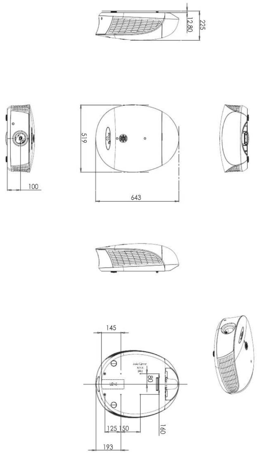
Figure 7-1. PD7170 Dimensions
Table 7-2 lists the signal types supported by each input on the PD7170.
7.3
Supported Timings
Table 7-2. Supported Signal Timings by Input
| Format Resolution | Refresh Rate (Hz) | Horizontal Frequency (kHz) | Pixel Frequency (MHz) | Supported? (√ = Yes, - = No) | ||||
| RGB | Component 1 Component 2 | HDMI 1 HDMI 2 | Composite S-Video | |||||
| 640x480 | 640x480 | 60.00 | 31.469 | 25.175 | √ | - | √ | - |
| 66.59 | 35.892 | 29.862 | √ | - | √ | - | ||
| 75.00 | 37.500 | 31.500 | √ | - | √ | - | ||
| 85.00 | 43.269 | 36.000 | √ | - | √ | - | ||
| 800x600 | 800x600 | 60.00 | 37.879 | 40.000 | √ | - | √ | - |
| 75.00 | 46.875 | 49.500 | √ | - | √ | - | ||
| 85.00 | 53.674 | 56.250 | √ | - | √ | - | ||
| 832x624 | 832x624 | 74.54 | 52.849 | 60.036 | √ | - | √ | - |
| 848x480 | 848x480 | 48.00 | 25.270 | 27.089 | √ | - | √ | - |
| 60.00 | 31.020 | 33.750 | √ | - | √ | - | ||
| 1024x768 | 1024x768 | 60.00 | 48.363 | 65.000 | √ | - | √ | - |
| 75.00 | 60.023 | 78.750 | √ | - | √ | - | ||
| 85.00 | 68.677 | 94.500 | √ | - | √ | - | ||
| 1280x720 | 1280x720 | 47.95 | 37.833 | 64.769 | √ | - | √ | - |
| 1280x1024 | 1280x1024 | 60.00 | 63.981 | 108.000 | √ | - | √ | - |
| 75.00 | 79.976 | 135.000 | √ | - | √ | - | ||
| 85.00 | 91.146 | 157.500 | √ | - | √ | - | ||
| 1600x1200 | 1600x1200 | 60.00 | 75.000 | 162.000 | √ | - | √ | - |
| 1680x1050 | 1680x1050 | 59.94 | 69.830 | 164.240 | √ | - | √ | - |
| 1920x1080 | 1920x1080 | 47.95 | 56.821 | 150.007 | √ | - | √ | - |
| 480/60i | 720x487 | 59.94 | 15.734 | 13.500 | - | √ | √ | √ |
| 480/60p | 720x483 | 59.94 | 31.469 | 27.000 | √ | √ | √ | - |
| 576/50i | 720x576 | 50.00 | 15.625 | 14.750 | - | √ | √ | √ |
| 576/50p | 720x576 | 50.00 | 31.250 | 29.000 | √ | √ | √ | - |
| 720/50p | 1280x720 | 50.00 | 37.500 | 75.250 | √ | √ | √ | - |
| 720/60p | 1280x720 | 60.00 | 45.000 | 74.250 | √ | √ | √ | - |
| 1080/50i | 1920x1080 | 50.00 | 28.125/31.250 | 74.250/72.000 | √ | √ | √ | - |
| 1080/60i | 1920x1080 | 59.94/60.00 | 33.716/33.750 | 74.175/74.250 | √ | √ | √ | - |
| 1080/24p | 1920x1080 | 23.98/24.00 | 26.978/27.000 | 74.175/74.250 | √ | √ | √ | - |
| Format | Resolution | Refresh Rate (Hz) | Horizontal Frequency (kHz) | Pixel Frequency (MHz) | Supported? (√ = Yes, - = No) | |||
| RGB | Component 1 Component 2 | HDMI 1 HDMI 2 | Composite S-Video | |||||
| 1080/50p | 1920x1080 | 50.00 | 56.250 | 148.500 | √ | √ | √ | - |
| 1080/60p | 1920x1080 | 59.94/60.00 | 67.433/67.500 | 148.350/148.500 | √ | √ | √ | - |
| NTSC 3.58 | - | 59.94/60.00 | 15.734/15.750 | 3.580 | - | - | - | √ |
| NTSC 4.43 | - | 59.94/60.00 | 15.734/15.750 | 4.430 | - | - | - | √ |
| PAL-B/G | - | 50.00 | 15.625 | 4.430 | - | - | - | √ |
| PAL-M | - | 59.94/60.00 | 15.734/15.750 | 3.580 | - | - | - | √ |
| PAL-N | - | 50.00 | 15.625 | 3.580 | - | - | - | √ |
| PAL-60 | - | 59.94/60.00 | 15.734/15.750 | 4.430 | - | - | - | √ |
| SECAM | - | 50.00 | 13.500 | 4.250/4.410 | - | - | - | √ |
Part No. 020-0882-01 rev. A May 2008
- PD7170 Home Theater Projector
- TWO YEAR LIMITED WARRANTY
- WHAT IS COVERED UNDER THE TERMS OF THIS LIMITED WARRANTY:
- WHAT IS NOT COVERED UNDER THE TERMS OF THIS LIMITED WARRANTY:
- RIGHTS, LIMITS AND EXCLUSIONS:
- EFFECTIVE WARRANTY DATE:
- IMPORTANT – WARRANTY REGISTRATION:
- CONTACT A PLANAR AUTHORIZED SERVICE CENTER TO OBTAIN SERVICE:
- COPYRIGHT AND TRADEMARKS:
- ADDITIONAL INFORMATION:
- PLANAR VIDEO PRODUCT INFORMATION RETAIN THIS INFORMATION FOR YOUR RECORDS
- Important Safety Instructions
- WARNING
- Compliance Information
- DECLARATION OF CONFORMITY:
- FCC PART 15:
- INDUSTRY CANADA (ICES-003):
- IMPORTANT RECYCLE INSTRUCTIONS
- DISPOSAL OF OLD ELECTRICAL AND ELECTRONIC EQUIPMENT (Applicable throughout the European Union and other European countries with separate collection programs)
- Table of Contents
- TWO YEAR LIMITED WARRANTY ....iii
- Important Safety Instructions ...... vi
- Compliance Information ......vii
- Introduction ...... 1
- Controls and Functions .... 5
- Installation 13
- Serial Communications 69
- Specifications 79
- Notes:
- List Of Figures
- About This Manual
- Note
- Using This Manual
- Description, Features and Benefits
- Parts List
- Optional Accessories:
- Controls and Functions
- • TOP IR SENSOR
- - SYSTEM KEYPAD
- SOURCE
- Cursor Buttons (▲, ◀, ▼, ▶)
- ENTER ( )
- MENU
- • POWER BUTTON/STATUS LED
- - EXHAUST VENT
- - INTAKE VENT
- • PROJECTION LENS
- - FRONT IR SENSOR
- 2.2
- PD7170 Rear Panel
- HDMI 1 (Digital)
- POWER INPUT (100 to 240 VAC)
- RGB
- COMPONENT 2
- COMPONENT 1/SCART (RCA connectors)
- VIDEO
- S-VIDEO
- IR INPUT
- TRIGGER 1
- 11.RS-232
- 2.3
- PD7170 Remote Control
- ON
- OFF
- Source Selection Buttons (1-5):
- Cursor Buttons (▲, ◀, ▼, ▶)
- ENTER
- Aspect Ratio Selection Button
- MENU
- Memory Preset Buttons (M1 / M2 / M3)
- Picture Adjustment Buttons:
- Contrast
- Brightness
- Sharpness (SHARP)
- Gamma (GAMMA)
- Overscan (OS)
- Noise Reduction (NR)
- LIGHT
- Picture-In-Picture (PIP) Controls:
- PIP
- SWAP
- 3.1
- Remote Control
- Notes on Batteries
- Notes on Remote Control Operation
- 3.2
- Quick Setup
- 3.3
- Installation
- Considerations
- Estimating Throw Distance
- Folded Optics
- Other Considerations ▶
- Lens Replacement
- 3.5
- Mounting the PD7170
- 3.6
- Connections to the PD7170
- Connector Panel Access
- Tip
- Connecting 12-Volt Trigger Output to External Theater Equipment
- Connecting an External IR Receiver
- 3.7
- Turning on the Power
- 3.8
- Lens Adjustments
- Changing the OSD Language
- 3.10
- Adjusting the Picture Orientation
- Operation
- Selecting Video Memory
- Selecting an Aspect Ratio
- Selecting An Input Source
- 4.4
- Using Picture-In-Picture (PIP)
- 4.5
- Using the On-Screen Menus
- You must enter a passcode to access the Save ISF sub-menu.
- Figure 4-15. PD7170 Control Menu
- Maintenance and Troubleshooting
- Lamp Replacement
- 5.2
- Troubleshooting Tips
- Serial Communications
- 6.1
- RS-232 Connection and Port Configuration
- 6.2
- Serial Command Syntax
- Operations Commands
- 7.1
- PD7170 Specifications
- PD7170 Dimensions
- 7.3
- Supported Timings
Brand : Planar
Model : PD7170
Category : Video projector