C10-UM - Wall mount Pelco - Free user manual and instructions
Find the device manual for free C10-UM Pelco in PDF.


| Product Type | Universal indoor camera mount |
| Compatible Cameras | Box type cameras with 1/4-20 inch mounting hole |
| Maximum Camera Weight | 7 lb (3.18 kg) |
| Mounting Options | Wall, ceiling, or T-rail |
| Pan Adjustment | 360 degrees |
| Tilt Adjustment | 90 degrees |
| Extension Tubes Included | 1.75 in (4.45 cm) and 3.25 in (8.25 cm) |
| Mounting Plate | Fits standard 2x4 in (5.08x10.16 cm) electrical box |
| Ball Socket | Includes ball stud, anvil, sleeve, mounting nut, and set screw |
| Hardware Required | 1/8-inch Allen wrench (not supplied) |
| Package Contents | Mounting plate, 2 extension tubes, ball socket assembly, T-bar clip |
| Material | Metal (aluminum/steel - not specified) |
| Color | Not specified (likely white or silver) |
| Installation Surface | Solid wall, ceiling, or T-rail |
| Environmental Rating | Indoor use only |
| Warranty | 1 year (defects in material/workmanship) |
| Compliance | RoHS (2002/95/EC), WEEE (2002/96/EC) |
| Application | Security camera mounting in commercial or residential settings |
Frequently Asked Questions - C10-UM Pelco
User questions about C10-UM Pelco
0 question about this device. Answer the ones you know or ask your own.
Ask a new question about this device
Download the instructions for your Wall mount in PDF format for free! Find your manual C10-UM - Pelco and take your electronic device back in hand. On this page are published all the documents necessary for the use of your device. C10-UM by Pelco.
USER MANUAL C10-UM Pelco
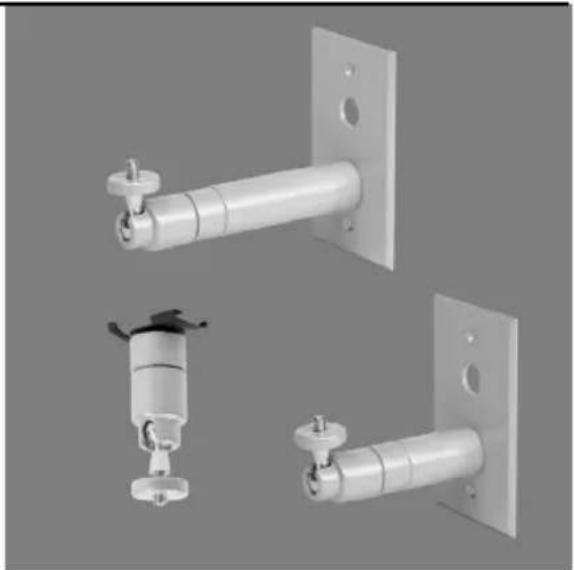
C10-UM Universal
Indoor Camera Mount
natural_image
Three metallic wall-mounted sensors with mounting brackets and mounting holes, shown from different angles (no text or symbols visible)C2237M (1/08)
Description 4
Parts List....4
Package Contents....5
Installation 6
Ceiling Mount 6
Wall Mount. 7
Compact Camera Models 7
Full-Size Camera Models 8
T-Rail Mount....9
The C10-UM is a universal camera mount kit that includes all the components for wall, ceiling or T-rail clip installations, for most box type cameras with 1/4 x 20-inch mounting holes. The kit supports cameras weighing up to 7 pounds (3.18 kg). The ball socket of the kit allows for 360 degree pan adjustment and 90 degree tilt adjustment.
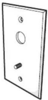
The mounting plate is designed to attach a standard 2 x 4-inch (5.08 x 10.16 cm) electrical box, or it can be flush mounted to the ceiling or a wall (hardware not supplied). A T-rail clip is included for installations where the mounting plate cannot be used.
NOTE: This mount kit is not recommended for use with enclosures.
PARTS LIST
Qty Description
1 Mounting plate
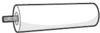
1 Extension tube, 3.35-inch (8.25 cm)
1 Extension tube, 1.75-inch (4.45 cm)
1 Ball socket assembly (includes ball stud, anvil, sleeve, mounting nut, and set screw)
1 T-bar clip
PACKAGE CONTENTS
The following diagram shows the box contents. When installing the C10-UM, refer to this diagram.

SHIPPING BOX
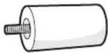
1.75 IN. (4.45 CM) TUBE 1 EA.
natural_image
Simple line drawing of a double door with three circular cutouts and a single handle (no text or symbols)MOUNTING PLATE
natural_image
Simple line drawing of a cylindrical object with a central screw-like feature (no text or symbols)3.25 IN. (8.25 CM) TUBE 1 EA.
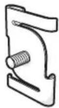
T-BAR CLIP
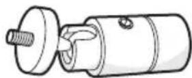
BALL SOCKET
CEILING MOUNT
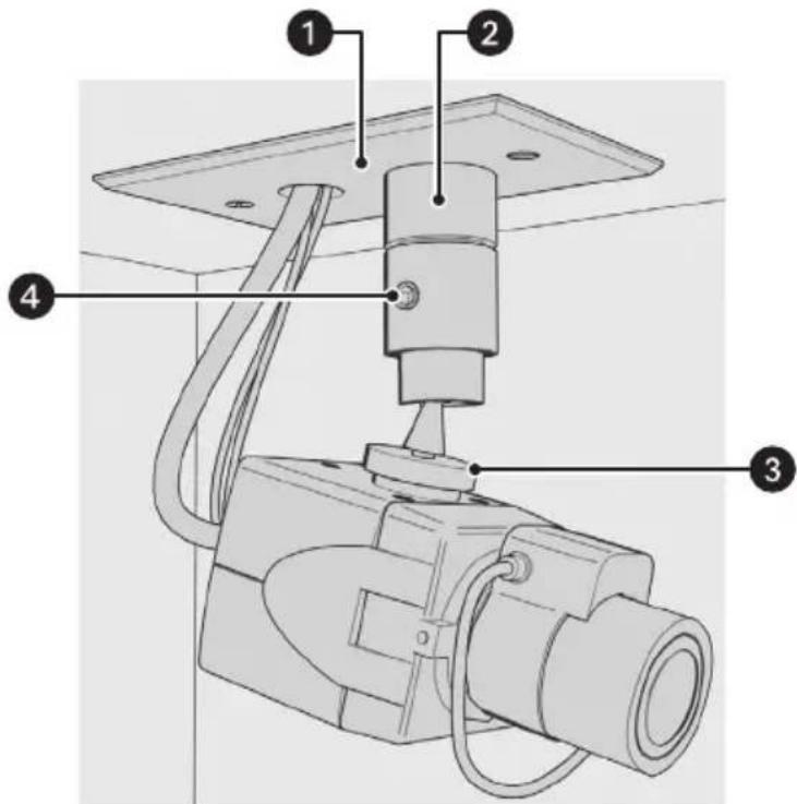
Figure 1. Ceiling Mount Installation
To install the mount to a ceiling refer to Figure 1, and then complete the following steps:
- Pull the wire and cable for the camera through the mounting plate, and then attach the mounting plate to the mounting surface (hardware not supplied).
- Attach the ball socket to the threaded stud on the mounting plate.
- Attach the camera to the 1/4-20 threaded stud on the ball socket, and then tighten the adjustment ring, and then tighten the adjustment ring.
- Use an 1/8-inch Allen wrench (not provided) to loosen the set screw on the ball socket to position the camera, and then retighten the set screw.
WALL MOUNT
COMPACT CAMERA MODELS
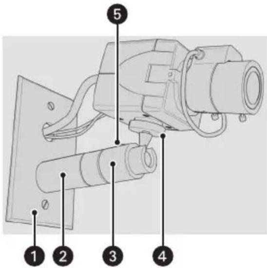
Figure 2. Wall Mount Installation for Compact Camera Models
To install the mount to a wall refer to Figure 2, and then complete the following steps:
- Pull the wire and cable for the camera through the mounting plate, and then attach the mounting plate to the mounting surface (hardware not supplied).
- Attach the 1.75-inch (4.45 cm) tube to the threaded stud on the mounting plate.
- Attach the ball socket to the threaded stud on the end of the tube.
- Attach the camera to the 1/4-20 threaded stud on the ball socket, and then tighten the adjustment ring.
- Use an 1/8-inch Allen wrench (not provided) to loosen the set screw on the ball socket to position the camera, and then retighten the set screw.
- Connect the wires and cable to the back of the camera (refer to the Installation/Operation manual supplied with the camera for instructions).
FULL-SIZE CAMERA MODELS
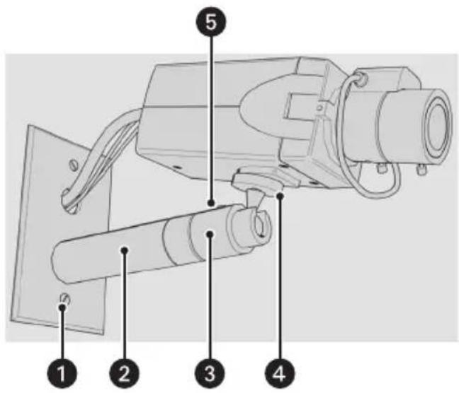
Figure 3. Wall Mount Installation for Full-Size Camera Models
To install the mount to a wall refer to Figure 3, and then complete the following steps:
- Pull the wire and cable for the camera through the mounting plate, and then attach the mounting plate to the mounting surface (hardware not supplied).
- Attach the 3.25-inch (8.25 cm) tube to the threaded stud on the mounting plate.
- Attach the ball socket to the threaded stud on the end of the tube.
- Attach the camera to the 1/4-20 threaded stud on the ball socket, and then tighten the adjustment ring.
- Use an 1/8-inch Allen wrench (not provided) to loosen the set screw on the ball socket to position the camera, and then retighten the set screw.
- Connect the wires and cable to the back of the camera (refer to the Installation/Operation manual supplied with the camera for instructions).
T-RAIL MOUNT
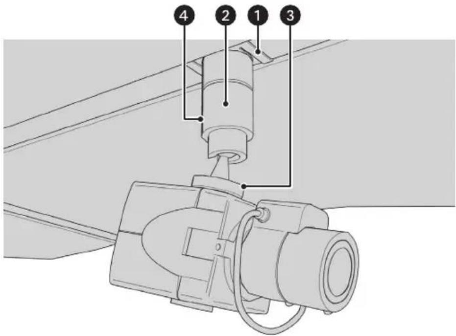
Figure 4. T-Rail Mount Installation
To install the mount to a T-rail refer to Figure 4, and then complete the following steps:
- Twist the T-rail clip onto the T-bar.
- Attach the ball socket to the threaded stud on the T-rail clip.
- Attach the camera to the 1/4-20 threaded stud on the ball socket.
- Use an 1/8-inch Allen wrench (not provided) to loosen the set screw on the ball socket to position the camera, and then retighten the set screw.
- Connect the wires and cable to the back of the camera (refer to the Installation/Operation manual supplied with the camera for instructions).
Green
The materials used in the manufacture of this document and its components are compliant to the requirements of Directive 2002/95/EC.

This equipment contains electrical or electronic components that must be recycled properly to comply with Directive 2002/96/EC of the European Union regarding the disposal of waste electrical and electronic equipment (WEEE). Contact your local dealer for procedures for recycling this equipment.
WARRANTY
Pelco will repair or replace, without charge, any merchandise proved defective in material or workmanship for a period of one year after the date of shipment.
Exceptions to this warranty are as noted below:
- Five years on fiber optic products and TW3000 Series unshielded twisted pair (UTP) transmission products.
- Three years on Spectra ^® IV products.
- Three years on Genex ^® Series products (multiplexers, server, and keyboard).
- Three years on DX Series digital video recorders, DVR5100 Series digital video recorders, DigitalSENTRY ^ Series hardware products, DVX Series digital video recorders, NVR300 Series network video recorders, and Endura ^ Series distributed network-based video products.
- Three years on Camclosure ^® and Pelco-branded fixed camera models, except the CC3701H-2, CC3701H-2X, CC3751H-2, CC3651H-2X, MC3651H-2, and MC3651H-2X camera models, which have a five-year warranty.
- Three years on PMCL200/300/400 Series LCD monitors.
- Two years on standard motorized or fixed focal length lenses.
- Two years on Legacy ^® , CM6700/CM6800/CM9700 Series matrix, and DF5/DF8 Series fixed dome products.
- Two years on Spectra III ^™ , Spectra Mini, Esprit ^® , ExSite ^® , and PS20 scanners, including when used in continuous motion applications.
- Two years on Esprit and WW5700 Series window wiper (excluding wiper blades).
- Two years (except lamp and color wheel) on Digital Light Processing (DLP ^® ) displays. The lamp and color wheel will be covered for a period of 90 days. The air filter is not covered under warranty.
- Two years on Intelli-M ^ eIDC controllers.
• One year (except video heads) on video cassette recorders (VCRs). Video heads will be covered for a period of six months. - Six months on all pan and tilts, scanners, or preset lenses used in continuous motion applications (preset scan, tour, and auto scan modes).
Pelco will warrant all replacement parts and repairs for 90 days from the date of Pelco shipment. All goods requiring warranty repair shall be sent freight prepaid to a Pelco designated location. Repairs made necessary by reason of misuse, alteration, normal wear, or accident are not covered under this warranty.
Pelco assumes no risk and shall be subject to no liability for damages or loss resulting from the specific use or application made of the Products. Pelco's liability for any claim, whether based on breach of contract, negligence, infringement of any rights of any party or product liability, relating to the Products shall not exceed the price paid by the Dealer to Pelco for such Products. In no event will Pelco be liable for any special, incidental, or consequential damages (including loss of use, loss of profit, and claims of third parties) however caused, whether by the negligence of Pelco or otherwise.
The above warranty provides the Dealer with specific legal rights. The Dealer may also have additional rights, which are subject to variation from state to state.
If a warranty repair is required, the Dealer must contact Pelco at (800) 289-9100 or (559) 292-1981 to obtain a Repair Authorization number (RA), and provide the following information:
- Model and serial number
- Date of shipment, P.O. number, sales order number, or Pelco invoice number
- Details of the defect or problem
If there is a dispute regarding the warranty of a product that does not fall under the warranty conditions stated above, please include a written explanation with the product when returned.
Method of return shipment shall be the same or equal to the method by which the item was received by Pelco.
RETURNS
To expedite parts returned for repair or credit, please call Pelco at (800) 289-9100 or (559) 292-1981 to obtain an authorization number (CA number if returned for credit, and RA number if returned for repair) and designated return location.
All merchandise returned for credit may be subject to a 20 percent restocking and refurbishing charge.
Goods returned for repair or credit should be clearly identified with the assigned CA or RA number and freight should be prepaid.
1-8-08
REVISION HISTORY
Manual # Date Comments
C2237M 1/08 Original version.
Pelco, the Pelco logo, Camclosure, DigitalSENTRY, Endura, Esprit, ExSite, Genex, Intelli-M, Legacy, and Spectra are registered trademarks of Pelco, Inc. Spectra III is a trademark of Pelco, Inc. © Copyright 2008, Pelco, Inc. All rights reserved.
DLP is a registered trademark of Texas Instruments Incorporated. All rights reserved.

Worldwide Headquarters 3500 Pelco Way Clovis, California 93612 USA
USA & Canada
Tel: 800/289-9100
Fax: 800/289-9150
International
Tel: 1-559/292-1981
Fax: 1-559/348-1120
www.pelco.com
ISO9001
Brand : Pelco
Model : C10-UM
Category : Wall mount