F90A1001 - Air Conditioning HONEYWELL - Free user manual and instructions
Find the device manual for free F90A1001 HONEYWELL in PDF.

User questions about F90A1001 HONEYWELL
0 question about this device. Answer the ones you know or ask your own.
Ask a new question about this device
Download the instructions for your Air Conditioning in PDF format for free! Find your manual F90A1001 - HONEYWELL and take your electronic device back in hand. On this page are published all the documents necessary for the use of your device. F90A1001 by HONEYWELL.
USER MANUAL F90A1001 HONEYWELL
Commercial Electronic Air Cleaner
PRODUCT DATA
natural_image
Exterior view of a black industrial fan or electronic device with visible grille and control panel (no text or symbols)APPLICATION
The F90A,B Self-Contained Commercial Electronic Air Cleaners are ceiling-mounted and remove airborne contaminants such as tobacco and cooking smoke, dust, pollen, bacteria, and larger viruses from the air circulated through the unit.
FEATURES
- Removes up to 95 percent of the staining dirt from the air, as measured by the Initial Dust Spot Method using atmospheric dust; refer to the American Society of Heating, Refrigerating, and Air Conditioning Engineers (ASHRAE) Standard 52-76.
- Provides Coanda air distribution by drawing in dirty air from below, cleaning it electronically, and discharging the clean air in four directions parallel with the ceiling.
• Three-speed fan circulates up to 1250 cfm (35 m3/min) for F90A and 550 cfm (15.5 m3/min) for F90B. - Solid state power supply is self-regulating, maintains peak efficiency over a wide range of cell dirt loading conditions, and provides nonlethal current levels.
- Interlock switch prevents operation when the cover is open or the grille is not in place.
- Heavy duty commercial cells, prefilter, and grille are removable for cleaning.
- Three-position adjustable discharge louvers control the direction of discharged air.
- Light emitting diodes (LEDs) indicate ON and CHECK; WASH LED optional.
- Test button shows presence of high voltage.
• Available with gray finish or woodgrain with black trim. - Optional hard-wired remote control assembly (part number 190097B).
- Optional carbon filters (part number 202614) for ozone and odor control.
- READ AND SAVE THESE INSTRUCTIONS
Contents
Application 1
Features 1
Specifications 2
Ordering Information 2
Planning the Installation 3
Installation 6
Checkout 12
Adjustments 12
Service 12
Electrical Troubleshooting 16
Replacement Parts List/Exploded View 22
Limited One-Year Warranty 24
SPECIFICATIONS
IMPORTANT
The specifications given in this publication do not include normal manufacturing tolerances. Therefore, a particular unit may not exactly match the listed specifications. Also, this product is tested and calibrated under closely controlled conditions, and some minor differences in performance can be expected if those conditions are changed.
Model:
F90A,B Self-Contained Commercial Electronic Air Cleaners. Contains one or two FC37B heavy duty commercial cells, a power supply assembly, one or two prefilters, cover with grille, a power and speed control switch, a performance selection switch, a test button, a three-speed motor driven fan, an interlock switch for the cover and grille, a power cord, and LED indication of system operation.
Color:
Available with gray finish or woodgrain with black trim.
Solid State Power Supply Assembly:
F90A, 120 Vac, 60 Hz: 203361E
F90A, 220/240 Vac, 50 Hz: 203361J
Electrical Ratings:
Voltage and Frequency (specify when ordering):
120 Vac, 60 Hz
220/240 Vac, 50 Hz
Current and Power Consumption:
| Model | Fan Setting | Current (A) | Power (W) |
| F90A, 120 z150 | HI | 2.6 | 270 |
| MED | 2.0 | 215 | |
| LOW | 1.8 | 185 | |
| 96A, 220/250 Vac, z150 | HI | 1.4 | 270 |
| MED | 1.0 | 215 | |
| LOW | .8 | 85 |
Air Flow Capacity:
| Model | Fan Setting | cfm | m^3 | uite/ |
| 96A | HI | 1250 | 35.0 | |
| MED | 1020 | 29.0 | ||
| LOW | 800 | 23.0 |
Efficiency:
Up to 92% efficient as measured by the Initial Dust Spot Method using atmospheric dust, according to the American Society of Heating, Refrigeration, and Air Conditioning Engineers (ASHRAE) Standard 52-76.
Ambient Temperature Rating:
Shipping and Storage: -20^ to +120^ ( -29^ to +49^ ).
Operating: The F90 is intended for use at ambient temperatures that usually are not higher than 90^ F ( 32^ C) but for brief periods, may be as high as 120^ F ( 49^ C))
ORDERING INFORMATION
If you have additional questions, need further information, or would like to comment on our products or services, please write or phone:
- Your local Honeywell Commercial Air Products Distributor.
2. Air-Pure Systems
16873 Fish Point Rd. SE
Prior Lake, MN 55372-1714
Phone: (800) 998-1919
Fax: (800) 221-3248
www.cleanairfacility.com
Shipping and Installation Weight:
| Model | Pounds | Kilograms | |
| F90A | Heavy Duty Commercial Cell | 9.2 (Each) | 4.2 (Each) |
| Shipping Weight | 70.0 | 31.5 | |
| Installed Weight | 65.0 | 29.5 |
Dimensions:
See Figs. 1 and 2.
Approvals:
Underwriters Laboratories Inc. listed: File No. E30954, Guide No. AGGZ (120 Vac units only).
Canadian Standards Association listed: File No. LR19060 (120 Vac units only).
U.S. FCC Class B limits for RFI, Computing Devices Rules, Canadian EMI Standard.
Replacement Parts and Accessories:
See Parts List on page 22.
text_image
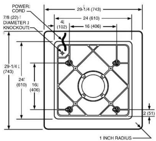
POWERU CORD 7/8 (22) DIAMETER J KNOCKOUTI 29-1/4 (743) 4L (102) 24 (610) 16 (406) 29-1/4 L (743) 24' (610) 16' (406) 2 (51) 1 INCH RADIUS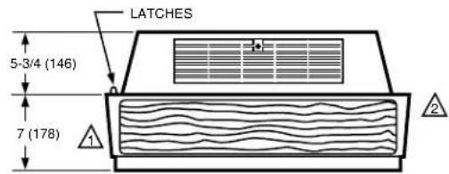
text_image
LATCHES 5-3/4 (146) 7 (178)
ALLOW AT LEAST 16 INCHES (406 MILLIMETERS) FROM FRONT OF F90 TO WALL FOR INSTALLATION AND REMOVAL OF CELLS.

ALLOW AT LEAST 9 INCHES (229 MILLIMETERS) FROM BACK OF F90 TO WALL FOR REMOVAL OF COVER.
M1530
Fig. 1. F90A installation dimensions in in. (mm).
text_image
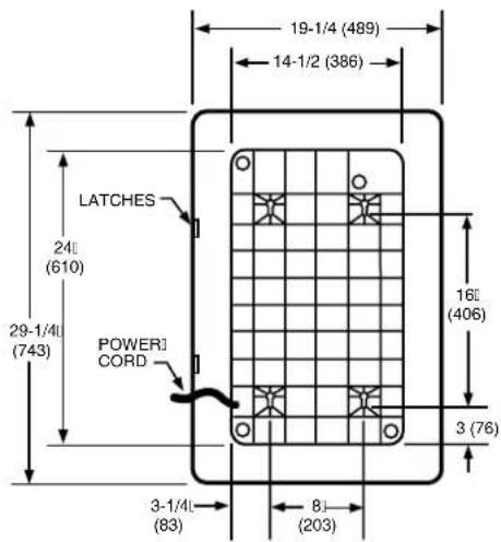
19-1/4 (489) 14-1/2 (386) LATCHES 24 (610) 29-1/4 (743) POWER1 CORD 16 (406) 3 (76) 3-1/4 (83) 8 (203)
text_image
5-3/4 (146) 7 (178)
ALLOW AT LEAST 16 INCHES (406 MILLIMETERS) FROM FRONT OF F90B TO WALL FOR INSTALLATION AND REMOVAL OF CELLS.

ALLOW AT LEAST 9 INCHES (229 MILLIMETERS) FROM BACK OF F90B TO WALL FOR REMOVAL OF COVER.
M919
Fig. 2. F90B installation dimensions in in. (mm).
PLANNING THE INSTALLATION

WARNING
Explosion Hazard.
Can cause property damage, severe injury, or death.
-
Do not install or use the F90 where there is any danger of gas, vapor, or dust explosion.
-
Do not install or use the F90 if explosion-proof electrical fixtures are specified.
Application and Operation
The F90 Self-Contained Electronic Air Cleaner is used where overhead air cleaning is required (restaurants, conference rooms, lounges, and offices).
The F90 provides its own air circulation and is used in any situation that requires the removal of contamination from an enclosed area.
The F90 is not explosion-proof. Do not use the F90 where dangerous levels of potentially explosive gases, vapors, or dusts are present in the cleaning area.
The F90 is equipped with two standard light-emitting diodes (LEDs) and one optional LED.
ON LED: Lights when the solid state power supply is powered and operating normally.
CHECK LED: Lights if the F90 requires service or if the test button is pressed.
WASH LED (if used): Lights when cell washing is overdue.
To understand the operating sequence of the F90, refer to Fig. 3.
Determine Number of F90 Needed
The sizing procedure determines the number of F90s needed for any application. The correct number required for a particular application depends on:
— type of contamination.
— number of occupants.
— volume of the room.
— use of the room.
— outdoor air quality.
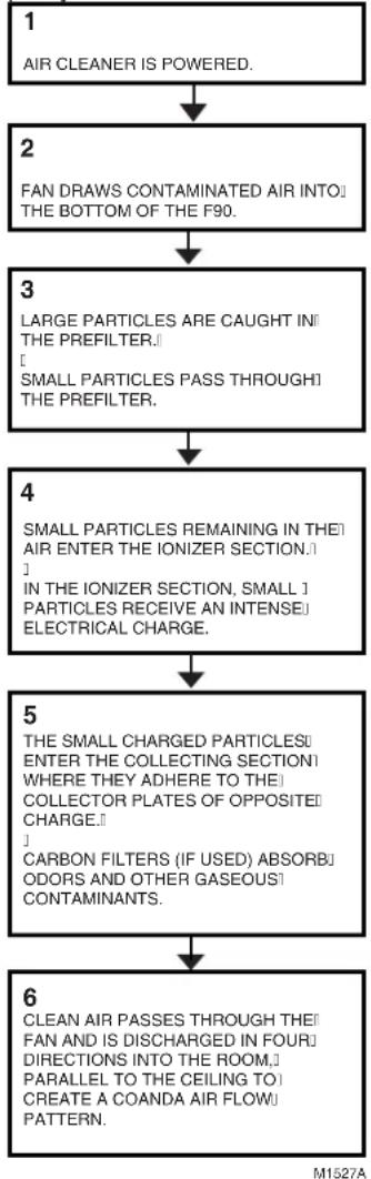
flowchart
graph TD
    A["1 AIR CLEANER IS POWERED."] --> B["2 FAN DRAWS CONTAMINATED AIR INTO THE BOTTOM OF THE F90."]
    B --> C["3 LARGE PARTICLES ARE CAUGHT IN THE PREFILTER. SMALL PARTICLES PASS THROUGH THE PREFILTER."]
    C --> D["4 SMALL PARTICLES REMAINING IN THEIR AIR ENTER THE IONIZER SECTION. IN THE IONIZER SECTION, SMALL PARTICLES RECEIVE AN INTENSE ELECTRICAL CHARGE."]
    D --> E["5 THE SMALL CHARGED PARTICLES ENTER THE COLLECTING SECTION WHERE THEY ADHERE TO THE COLLECTOR PLATES OF OPPOSITE CHARGE. CARBON FILTERS (IF USED) ABSORBODORS AND OTHER GASEOUS CONTAMINANTS."]
    E --> F["6 CLEAN AIR PASSES THROUGH THEIR FAN AND IS DISCHARGED IN FOUR DIRECTIONS INTO THE ROOM. PARALLEL TO THE CEILING TO CREATE A COANDA AIR FLOW PATTERN."]
Fig. 3. F90 operating sequence.
This sizing information in the following Examples 1, 2, and 3 was generated using the ASHRAE Handbook of Fundamentals, 1990 and the ASHRAE Standard 62-1989, Ventilation for Acceptable Indoor Quality. These examples simplify the sizing procedure for most applications. Use this information as a guide; however, keep in mind that the F90 has different capacities for each fan speed (see Specifications section).
The number of air changes per hour determines the number of F90s needed. More air changes per hour than indicated are unnecessary because the ASHRAE data from which these examples were constructed is conservative. Fewer air changes per hour can be compensated for by bringing in more outdoor air to maintain low contaminant levels or tolerating a partially cleaned atmosphere. Either may be acceptable to some users.
Regardless of the method used for calculation, the architectural features, lighting fixtures, sprinkler system, ducts, and grilles in the room to be cleaned may influence the number of F90s required. For ambient air cleaning, establish a uniform airflow pattern throughout the entire space. When there is a lack of mounting space, fewer F90s than indicated may be installed. More F90s may be required for oddly-shaped rooms that do not have even airflow.
If any questions should arise, consult your full-service distributor Honeywell Commercial Air Products.
To calculate the number of F90s needed using occupant load, refer to Example 2 (page 6).
To calculate the number of F90s needed using air changes per hour and room volume, refer to Example 1 (page 5) or Example 3 (page 6).
Choose Location
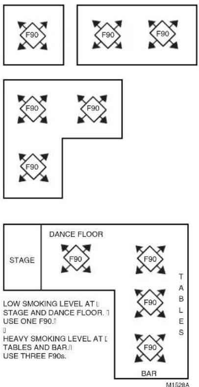
Mount the F90 on the ceiling near the center of the room. A 45^ diagonal mounting prevents stale air build-up in corners and may allow use of F90s at lower speeds. See Fig. 4. In larger rooms, divide the area into sections and mount an F90 in the center of each section. In rooms requiring varying levels of air cleaning, concentrate F90s where air cleaning is required most. See Fig. 4.
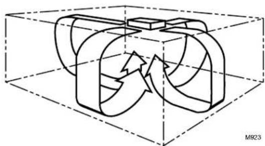
NOTE: To assure even air distribution, the F90 draws air into the bottom of the air cleaner and discharges air in four directions as shown in Fig. 5. This Coanda air flow pattern assures that the clean air is distributed to all parts of the space. Also, if possible, mount the F90 to aid the air circulation already established in the room.
text_image
F90 F90 F90 F90 F90 F90 F90 STAGE DANCE FLOOR F90 F90 T TABLES LE HEAVY SMOKING LEVEL AT [] TABLES AND BAR.[] USE THREE F90s. BAR M1528AFig. 4. F90 mounting considerations.
natural_image
3D diagram of a mechanical component inside a transparent cube, showing internal flow arrows (no text or symbols)Fig. 5. F90 Coanda air flow pattern.
Outdoor Air
ASHRAE Standard 62-89 specifies that every commercial space be provided with fifteen cfm per occupant of outdoor air to replenish oxygen and dilute CO2. If other internal sources of gaseous contamination are present, additional outside air is needed to dilute the contamination.
EXAMPLE: An office requires 20 cfm per person because the standard estimates some smoking, some copy machine operation, etc. The standard assumes outdoor air will be cleaned to less than 75 micrograms per cubic meter prior to introduction into the space. ASHRAE Standard 62-89 states that supplemental air cleaning to control smoke or additional outside air must be provided as required.
Example 1. Sizing by Air Changes per Hour and Room Volume
An office measures 40 x 45 feet (12 x 14 meters) with a 15 foot (4.5 meter) ceiling. How many F90As should be installed?
Solution:
- Find the room volume: 40 x 45 x 15 feet = 27,000 cubic feet, (12 x 14 x 4.5 meters = 756 cubic meters).
- Assuming seven air changes per hour, with 27,000 cubic feet (756 cubic meters) volume, the graph below indicates three F90As are required.
- Clean outdoor air is also required to replenish oxygen and dilute gaseous contaminants. 20 cfm per person is required for offices.
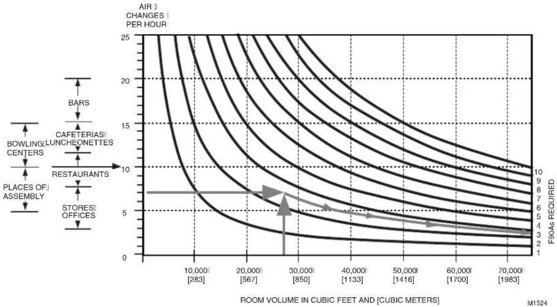
line
| ROOM VOLUME IN CUBIC FEET AND [CUBIC METERS] | AIR CHANGES PER HOUR | | ------------------------------------------- | --------------------- | | 10,000 [283] | 25 | | 20,000 [567] | 20 | | 30,000 [850] | 15 | | 40,000 [1133] | 10 | | 50,000 [1416] | 5 | | 60,000 [1700] | 3 | | 70,000 [1983] | 2 |Example 2. Sizing by Occupant Load
A cocktail lounge averages 85 occupants. How many F90As should be installed?
Solution:
F90As Required = ASHRAE Recommended Air Circulation/Minute
F90A Capacity
- ASHRAE recommended minimum air circulation is 30 cubic feet per minute (cfm) (0.85 m ^3 /minute) per person. For 85 people, the recommended air circulation would be: 85 people x 30 cfm (0.85 m ^3 /minute) per person = 2550 cfm (72 m ^3 minute).
- F90A capacity (HI setting) is 1250 cfm (35 m ^3 /minute).
Number of F90A's Required = 2550 cfm = 2 F90A's 72 m ^3 /minute = 2 F90As
1250 cfm 35 m3/minute - Clean outdoor air is also required to replenish oxygen and dilute gaseous contaminants. 30 cfm per person is required for bars and cocktail lounges.
EXAMPLE 3. Sizing by Air Changes per Hour and Room Volume
A shop proprietor wants to use F90As to remove high levels of smoke from the air. The shop is 25 x 40 feet (8 x 12 meters) with a 15 feet (4.5 meters) ceiling. How many F90As are required?
Guideline: In the absence of other information, select the correct number of F90A units to provide between 10 and 20 air changes per hour, depending on contaminant level. The F90As should be located directly above or as close as possible to the source of contamination.
Solution:
F90As required = Desired Air Circulation/Minute
F90A Capacity
- Calculate the volume of the room: 25 x 40 x 15 feet = 15,000 cubic feet, (8 x 12 x 4.5 meters = 432 cubic meters).
- Determine the volume of air to be circulated each hour. Ten air changes per hour are used here on the assumption that the intent is to reduce, but not completely eliminate, smoke. 15,000 cubic feet x 10 air changes/hour = 150,000 cubic feet/hour (432 cubic meters x 10 air changes/hour = 4320 cubic meters/hour)
- Determine the volume of air to be circulated each minute:
150,000 cubic feet/hour = 2500 cubic feet/minute (cfm) 4320 cubic feet/hour = 72 cubic meters/minute ( m^3/minute ) 60 minutes/hour 60 minutes/hour
- F90A capacity (HI setting is 1250 cfm (35 m ^3 /minute).
Number of F90As Required = 2500 cfm = 2 F90As 72 m³/minute = 2 F90As
1250 cfm 35 m ^3 /minute
INSTALLATION
When Installing this Product...
- Read these instructions carefully. Failure to follow them could damage the product or cause a hazardous condition.
- Check the ratings given in the instructions and on the product to assure the product is suitable for your application.
- Assure the installer is a trained, experienced service technician.
- After installation is complete, check out product operation as provided in these instructions.

WARNING
Explosion Hazard.
Can cause property damage, severe injury, or death.
-
Do not install or use the F90 where there is any danger of gas, vapor, or dust explosion.
-
Do not install or use the F90 if explosion-proof fixtures are specified.
Sharp Edges.
Can cause personal injury.
Wear protective gloves while handling the cells and prefilter to avoid cuts from the sharp metal edges, collection plates, and ionizer wires.

WARNING
Must be installed by only a Honeywell trained installer.

CAUTION
Do not connect the power supply until F90 is mounted. If the F90 is powered before an electrical check, be extremely careful to avoid electrical shock. Also, take care when working near the F90 moving parts.
Unpacking
-
All F90 components are packed in one box. Slide the F90 out of the box and remove all packaging material.
-
Carefully check all F90 components when unpacking.
- Check all packaging materials before discarding to assure no parts or papers are lost.
-
Use the mounting template marked on the outside of the box for easy installation.
-
Pull the two latches located on the front of the F90 cover. Swing the cover down and lift to disengage from the hinges.
- Remove the prefilter and cell from the channel guides.
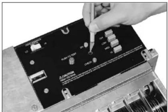
- If installing the optional WASH LED, remove the power supply switch plate. To install the WASH LED, see Fig. 6.
- Remove the power box from the unit. See Electrical Troubleshooting section for instructions.
Mounting

WARNING
Heavy Equipment. Can cause personal injury or equipment damage.
-
If the ceiling is not reinforced properly, the weight of the F90 could cause structural weakening and buckling. The unit can fall, presenting a danger to persons and equipment.
-
When using the keyhole slots for mounting, assure the washer diameter is larger than the keyhole diameter (3/4 in. [19 mm]) or assure the mounting screws are secured in the small keyhole slot.
IMPORTANT
- When mounting near walls, allow at least 16 in. (406 mm) for cell installation and removal and 15 in. (381 mm) for cover installation and removal. See Fig. 7.
- Select a structurally strong part of the ceiling or wall for mounting. Do not mount the F90 to a suspended ceiling, to plaster, or to wallboard. If necessary, construct strong framing to support the weight of the F90.
The F90 can be mounted in any of four ways:
- Mounted into a ceiling joist using lag screws. See Fig. 8.
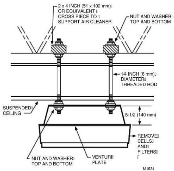
- Mounted into a suspended ceiling using threaded steel rods. See Fig. 9.
- Mounted into a ceiling joist or suspended ceiling using a transition plate accessory. See Figs. 10 and 11.
- Mounted into a wall using the wall mounting hardware accessory. See Fig. 12.
The F90 may also be mounted with lag bolts or threaded steel rods reaching down to the venturi plate. However, ensure the bolts or rods are short enough to avoid interfering with the cells. Assure 1-1/2 threads are visible beyond the nut.
For F90 installation dimensions, see Fig. 7.
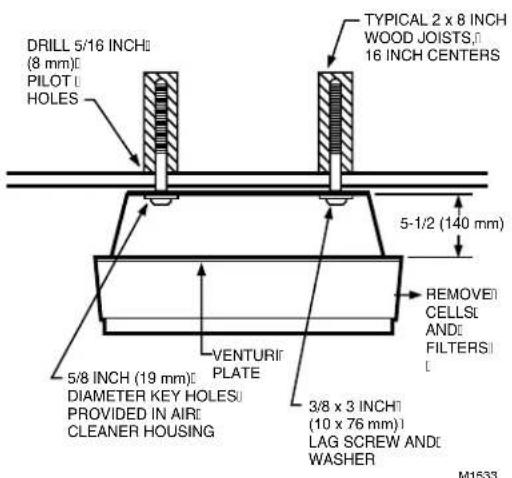
Mounting the F90 Using Lag Screws
- Locate the ceiling joists. See Fig. 8.
- Drill four 5/16 in. (8 mm) pilot holes in the joists using the mounting template to locate holes.
- Lift the F90 to the mounting location.
- Mount the F90 using four 3/8 in. x 3 in. (10 mm x 76 mm) lag screws and washers.
NOTE: Assure the washer size is larger than the 3/4 in. (19 mm) diameter of the keyhole or assure the mounting screws are secured in the small keyhole slot.
text_image
POST-DRAGON LD 19 PUSH TO PRINT OFF LINE MID CAUTION PUSH ORDER CHECK FOR PULSEING ITEMS FOR PULSEING ITEMS FOR PULSEING ITEMS FOR PULSEING ITEMS FOR PULSEING ITEMS FOR PULSEING ITEMS FOR PULSEING ITEMS FOR PULSEING ITEMS FOR PULSEING ITEMS FOR PULSEING ITEMS FOR PULSEING ITEMS FOR PULSEING ITEMS FOR PULSEING ITEMS FOR PULSEING ITEMS FOR PULSEING ITEMS FOR PULSEING ITEMS FOR PULSEING ITEMS FOR PULTRY ITEMS FOR PULTRY ITEMS FOR PULTRY ITEMS FOR PULTRY ITEMS FOR PULTRY ITEMS FOR PULTRY ITEMS FOR PULTRY ITEMS FOR PULTRY ITEMS FOR PULTRY ITEMS FOR PULTRY ITEMS FOR PULTRY ITEMS FOR PULTRY ITEMS FOR PULTRY ITEMS FOR PULTRY ITEMS FOR PULTRY ITEMS FOR PULTRY ITEMS FOR PULTRY ITEMS FOR FUTURES FOR FUTURES FOR FUTURES FOR FUTURES FOR FUTURES FOR FUTURES FOR FUTURES FOR FUTURES FOR FUTURES FOR FUTURES FOR FUTURES FOR FUTURES FOR FUTURES FOR FUTURES FOR FUTURES FOR FUTURES FOR FUTURES FOR FUTURES FOR FUTURES FOR FUTURES FOR FUTURS FOR FUTURS FOR FUTURS FOR FUTURS FOR FUTURS FOR FUTURS FOR FUTURS FOR FUTURS FOR FUTURS FOR FUTURS FOR FUTURS FOR FUTURS FOR FUTURS FOR FUTURS FOR FUTURS FOR FUTURS FOR FUTURS FOR FUTURE ITEMS- LOCATE WASH LED CUTOUT BEHIND SWITCH COVER ASSEMBLY STICKER.
text_image
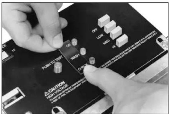
PERFORMANCE LD 1H PUSH TO TEST ON OFF LOW MD 1H CAUTION RED TO TEST A COVID-19 infection is caused by the COVID-19 infection. The COVID-19 infection is caused by the COVID-19 infection. It is caused by the COVID-19 infection. It is caused by the COVID-19 infection. It is caused by the COVID-19 infection. It is caused by the COVID-19 infection. It is caused by the COVID-19 infection. It is caused by the COVID-19 infection. It is caused by the COVID-19 infection. It is caused by the COVID-19 infection. It is caused by the COVID-19 infection. It's caused by the COVID-19 infection. It's caused by the COVID-19 infection. It's caused by the COVID-19 infection. It's caused by the COVID-19 infection. It's caused by the COVID-19 infection. It's caused by the COVID-19 infection. It's caused by the COVID-19 infection. It's caused by the COVID-19 infection. It's caused by the COVID-19 infection. It's causes from this case in the first 20 days of the year.- USE A KNIFE TO CUT A HOLE IN THE STICKER.
text_image
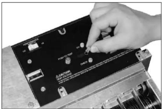
HOPCLOS 12 P POT TO TEST A CALYTON VER. COLDING OFFICE ON ON ON ON- PUSH LED LENS INTO PLACE. 4.
natural_image
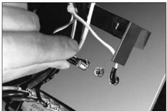
Close-up of a hand holding wires and connectors with a small circular component, no visible text or symbolsINSERT LED INTO LENS FROM BACK OF THE SWITCH COVER ASSEMBLY.
text_image
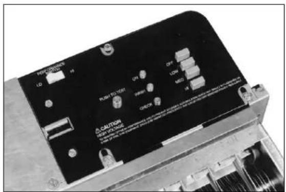
PHLMS TO TEST ON WASH CXO CAUTION HIGH VOLTAGE A 100% 100% 100% 100% 100% 100% 100% 100% 100% 100% 100% 100% 100% 100% 100% OFF LOW RED HI CLOSURE ADJUSTED FOR CAPSIBLE HIGH VOLTAGE AND NOT BE USED. THIS ISOMINAL ORDER FOR EACH ORDER IS USED. THIS ISOMINAL ORDER A 100% 100% 100% 100% 100% 100% 100% 100% 100% 100% 100% 100% 100% 100% 100% 100% 100% 100% 100% 100% 100% HIV CE H V X Y Z R S T U B N O P E F G H I J K L M N O P R S T U B N O P E F G H I J K L M N O P R S T U B N O P E- ATTACH NEW STICKER TO SWITCH U COVER ASSEMBLY.
text_image
KEYHOLE 3/8 (10) DIAMETER 3/4 (19) 3/8 (10) DIAMETER 9 (229)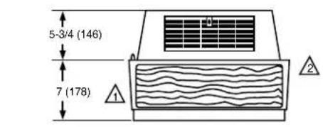
text_image
5-3/4 (146) 7 (178)ALLOW AT LEAST 16 INCHES (406 MILLIMETERS) FROM FRONT OF F90 TO WALL FOR INSTALLATION AND REMOVAL OF CELLS.
2 ALLOW AT LEAST 9 INCHES (229 MILLIMETERS) FROM BACK OF F90 TO WALL FOR REMOVAL OF COVER.
M920
Fig. 7. F90 installation dimensions in in. (mm).
text_image
DRILL 5/16 INCH (8 mm) PILOT HOLES TYPICAL 2 x 8 INCH WOOD JOISTS 16 INCH CENTERS 5-1/2 (140 mm) 5/8 INCH (19 mm) DIAMETER KEY HOLES PROVIDED IN AIR CLEANER HOUSING VENTURI PLATE REMOVE CELLS AND FILTERS 3/8 x 3 INCH (10 x 76 mm) LAG SCREW AND WASHER M1533Fig. 8. Mounting the F90 using lag screws in joist applications.
Mounting the F90 Using Threaded Steel Rod
- Arrange two 2 x 4 supports as shown in Fig. 9.
- Drill four 5/16 inch pilot holes through the supports using the mounting template to locate holes.
- Mount the steel rods to the supports.
- Lift the F90 to the mounting location.
- Mount the F90 to the steel rods by attaching the nuts and washers.
text_image
2 x 4 INCH (51 x 102 mm) OR EQUIVALENT CROSS PIECE TO SUPPORT AIR CLEANER NUT AND WASHERI TOP AND BOTTOM 1/4 INCH (6 mm) DIAMETER THREADED ROD SUSPENDED CEILING 5-1/2 (140 mm) REMOVE CELLS AND FILTERS NUT AND WASHERI TOP AND BOTTOM VENTURI PLATE M1534Fig. 9. Mounting the F90 using steel rods in suspended ceiling applications.
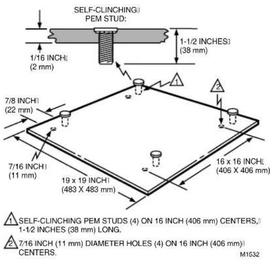
Mounting the F90A Using the 272577A Transition Plate (Accessory)
The transition plate (Fig. 10) allows the F90 to be mounted by one person. In the two-step process, the mounting plate is first secured directly to the ceiling joists. Then the F90 is mounted to the transition plate.
Eight flanged locknuts (four large, four small) and four 3/8 by 3 in. (10 by 76 mm) lag screws are provided with the transition plate. The four large locknuts adjust the F90 height, level the F90, and provide stops for the F90 top plate (when tightened). The four smaller locknuts secure the F90 to the ceiling joists.
- Screw a large height-adjusting nut on each stud. Assure that the large nut is screwed on with its flanged portion down.
- Position and level the height adjusting nuts so flanges are flush with the lag screw heads or the protruding threaded steel rods.
- Screw a small securing nut on each stud, leaving a 1/2 in. (13 mm) space between it and the height adjusting nut.
- Lift the F90 into position and locate the four studs.
- Raise the F90 so that the four studs pass through the keyhole openings.
- Slide the F90 horizontally so the studs are located at the slot end of each keyhole opening.
NOTE: As viewed from the F90 or floor side, the slot portion of each keyhole is above the surface of the top plate. Position the F90 so the studs are located at the slot end of each keyhole. When the securing nuts are tightened, they should nest firmly in the sockets to prevent any lateral movement.
text_image
SELF-CLINCHING PEM STUD: 1/16 INCH (2 mm) 7/8 INCH (22 mm) 7/16 INCH (11 mm) 19 x 19 INCH (483 X 483 mm) 16 x 16 INCH (406 X 406 mm) SELF-CLINCHING PEM STUDS (4) ON 16 INCH (406 mm) CENTERS, 1-1/2 INCHES (38 mm) LONG. 7/16 INCH (11 mm) DIAMETER HOLES (4) ON 16 INCH (406 mm) CENTERS. M1532Fig. 10. Mounting F90 using 272577A Transition Plate.
- Tighten the securing nuts until the F90 top plate engages the height adjusting nuts.
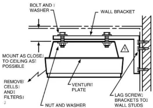
Mounting the F90 Using the 118636C Wall Mounting Kit (Accessory)
Two wall mounting brackets are used to support the F90. See Fig. 11. The two brackets must be mounted on the wall with 16 in. (406 mm) for the F90A or 8 in. (203 mm) for the F90B between centers so that the lag bolts will align with the F90 mounting holes. Fasten the brackets to the wall studs with lag screws. On masonry walls, use appropriate screw anchors.
Wiring
IMPORTANT
All wiring must comply with local codes and ordinances.
Power Cord
IMPORTANT
Power supply cord must not be concealed above the ceiling or behind the walls.
The F90, 120 Vac has a standard 3-prong plug on a 10 foot (3 meter) power cord. There must be a standard grounded outlet within 10 feet (3 meters) of the F90. The F90, 220/240 Vac power cord terminates in stripped leadwires for installation of a locally purchased plug.
- Do not use an extension cord to power the F90.
- Keep the power cord out of the reach of building occupants.
- Keep the power cord away from water.
- Do not route the power cord near sharp objects that can damage the cord insulation.
Permanent Wiring
- Loosen the two screws and remove the plate covering the wiring compartment.
-
Remove the power cord.
-
Cut the black and white wires of the power cord, leaving six inches from the electrical connector. Strip 1/2 in. (12 mm) insulation from the end of each wire.
- Cut the green wire flush with the electrical connector.
- Remove the power cord and strain relief bushing.
-
Install plug (provided) in the hole that contained the power cord.
-
Attach the conduit to the unit.
-
Run 3-strand, no. 14 wire through the conduit into the wiring compartment.
- Wire the F90 using the wiring diagram shown in Fig. 12. Assure the green wire is secured to the green grounding screw provided.
- Reinstall the wiring compartment plate and tighten the screws.
text_image
BOLT AND WASHER WALL BRACKET MOUNT AS CLOSE TO CEILING AS POSSIBLE REMOVE CELLS AND FILTERS VENTURI PLATE NUT AND WASHER LAG SCREW BRACKETS TO WALL STUDS1 REPLACE REAR LOUVERS WITH BLANK PLATE ON F90 SIDE ADJACENT TO THE WALL. M1536
Fig. 11. Mounting F90 using 118638C Mounting Kit.
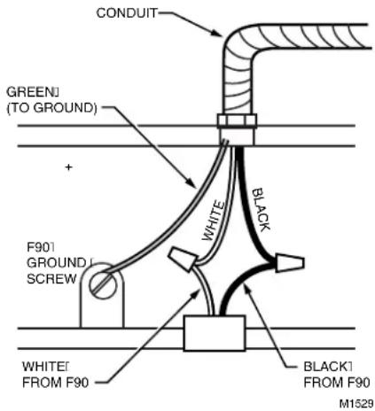
text_image
CONDUIT GREENI (TO GROUND) + F901 GROUND SCREW WHITE BLACK WHITE FROM F90 BLACK1 FROM F90 M1529Fig. 12. Wiring F90.
Installing Activated Carbon Filters, Cells, and Prefilters
- Insert the activated carbon filters (if used) into the channel guides closest to the fan.
- Inspect the cells for broken ionizer wires and bent collector plates. Moderately bent or warped collector plates can be bent back into shape. Broken ionizer wires must be replaced for top efficiency as instructed on page 15.
- Insert the cells into the channel guides until they touch the back stop of the F90. Assure the cell airflow arrow is pointing toward the fan. In this position, the ionizer wires are facing downward (away from the fan).
- Insert the prefilters into the channel guides until they touch the back of the channels.
Installing Cover
- Before installing, study the inside of the F90 cover. One end has two latches and the other has two hinge pins. To properly install the cover, connect the hinge pins to the hinges.
- Attach the hinge pins by lifting the cover above the hinge and lowering the pins into the hinges. If the cover is properly attached, it can hang below the F90.
- Carefully swing the opposite end of the cover upward and engage the latches. See Fig. 13. Assure the latches are connected properly.
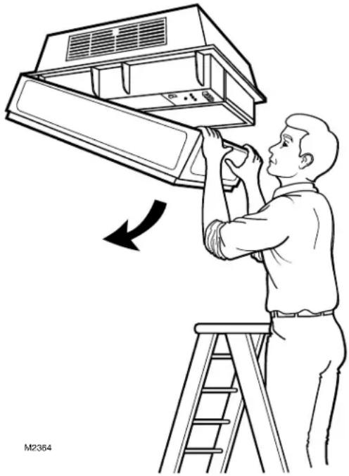
natural_image
Illustration of a person installing or adjusting an air conditioner cover on a ladder (no text or symbols present)Fig. 13. Opening and closing F90 cover.
CHECKOUT
Inspect The Installation
Be sure the F90:
Is securely fastened to the ceiling or wall.
☐ Does not interfere with normal occupant traffic.
Is properly oriented for good air circulation.
Cells are correctly oriented with air flow arrows pointing toward the fan.
Prefilters are properly installed below the cells.
Discharge louvers are securely installed.
Cover is securely latched.
☐ SYSTEM light turns on when fan is running.
☐ Fan stops and ON LED turns off when the cover is opened.
Surfaces and the installation area are wiped clean.
☐ Marked or nicked paint is retouched.
Check F90 Operation
Turn on power.
☐ Push the test button to assure the power supply is functioning at all three speeds.
☐ Use the manual switch on the F90, manual wall switch, or remote transmitter to assure that the fan runs correctly at all three speed settings.
Assure the ON LED lights when the fan is operating.
☐ Assure the WASH LED (if used) lights when the cells are removed, grille is closed, and F90 is turned on.
ADJUSTMENTS
Louver Adjustment

CAUTION
Do not operate air cleaner without the louvers installed.
The F90 plastic louvers can be repositioned to vary the airflow pattern. Three positions are available. Position 3 directs airflow along the ceiling. Positions 2 and 1 direct airflow downward. Use position 2 or 1 if ceiling staining is a problem or if beams or other obstacles disrupt airflow.
Louvers are shipped in position 1. Louvers can be adjusted as follows:
- Loosen screw by turning counterclockwise 2-1/2 turns. Do not remove screw.
- Push louvers up to disengage bottom tabs, and pull bottom of the louvers out slightly to desired position.
- Retighten the screw. Assure that the tabs on the bottom of the louvers are positively engaged with the F90 frame.
SERVICE

WARNING
Sharp Edges.
Can cause personal injury.
Wear protective gloves and carefully handle the cells and prefilters to avoid cuts from the sharp metal edges, collection plates, and ionizer wires.
Steam, Hot Water, Strong Detergent.
Can cause personal injury.
Wear rubber gloves, eye protection, and rubber apron for protection from the strong cleaning chemicals and hot temperatures.
IMPORTANT
The F90 and its components are susceptible to damage. Be careful when working with them to avoid equipment damage. Never use an acid base detergent to wash cells.
Cleaning the F90
The F90 removes a variety of contaminants from the air. As it cleans the air, the F90 cells and prefilters become dirty, lowering the cleaning efficiency. To maintain the F90 reliability and efficiency, regularly clean, inspect, and service the F90 cells and prefilters.
Clean cells with an alkaline base detergent solution. Soaking the cells in commercial or home electric dishwasher detergent, powder or liquid, works well. Use the hottest water possible (hotter than 160^ F ( 71^ C)). If soaking does not clean the cells, use high velocity detergent spray or steam. Full service distributors provide a regular cleaning service to commercial establishments.
The WASH LED (if used) lights when cell washing is overdue. When the WASH LED lights, wash the cells and wipe the ionizer wires. Frequent cell cleaning keeps WASH LED
from lighting.
The F90 needs servicing if it is damaged or if efficiency is substandard, if abnormal voltages are measured, or if the CHECK LED lights.
Opening the Cover and Removing the Cells and Prefilters

CAUTION
- Before servicing the F90, turn off power to the F90.
-
When servicing the F90, stand on a stable work platform or ladder.
-
Open the cover by pulling the two latches located on the front of the cover and swinging the cover down until it hangs. See Fig. 13.
- Remove the prefilter and the cell from the channel guides.
- Replace the activated carbon filter (if used), if it needs replacement.
Cleaning the Prefilter
- Shake out or vacuum the accumulated contaminants from the prefilter. If necessary, soak the prefilter in alkaline detergent solution. Do not soak the prefilter in an acid detergent solution or use high pressure water, air, or steam to clean the prefilter.
NOTE: Wash the cell before washing the prefilter. If the prefilter is washed first, lint residue from the prefilter will contaminate the wash water and deposit inside the cell. Dispose of the wash water after each use.
Cleaning the Cell Using Alkaline Base Detergent
WARNING
Hazardous Chemical. Can cause personal injury.
Wear rubber gloves, eye protection, and a rubber apron for protection from the strong cleaning chemicals. Keep detergent solution out of reach of children.
- Use a container such as a laundry tub or plastic tank that is large enough to hold at least one cell.
- Mix the alkaline base detergent with hot water, carefully following the instructions on the detergent package.
- Use commercial or home electric dishwasher detergent (either powder or liquid). Do not use soap or acid base cleaners or solvents.
- Assure the water temperature is between 150^ and 190^ (66°C and 88°C).
- If using cold water detergent, follow the instructions included with the detergent.
NOTE: Cold water detergent cleans less effectively than hot water detergent.
text_image
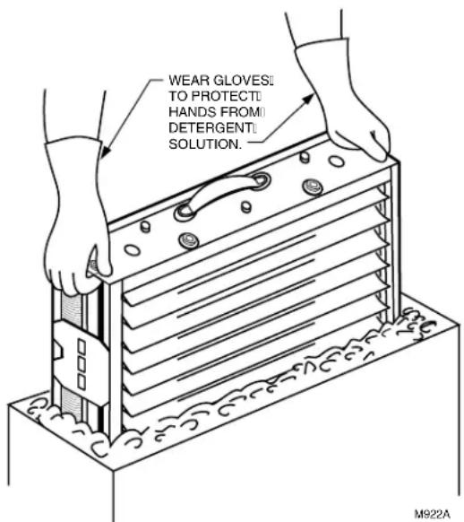
WEAR GLOVES: TO PROTECTI HANDS FROM DETERGENT: SOLUTION.Fig. 14. When cleaning cell, agitate in detergent solution.
- Carefully wipe off ionizer wires before prerinsing.
- Prerinse the cell in hot water before submerging in detergent.
- Soak the cell in the solution for up to 15 minutes. Agitate the cell in the solution if necessary. See Fig. 14.
- Remove the cell from the detergent solution.
- Place the cell in another container of clear hot water (150°F to 190°F (66°C to 88°C)) for final rinsing. Rinse the cells for five to ten minutes.
-
Remove the cell from the rinse water. Allow the cell to drain and dry before energizing. Stand cell on one corner for optimum water drainage.
-
Carefully wipe ionizer wires to remove any remaining residue.
-
Check the collection plates of the cell for any detergent residue. If any residue is remaining, repeat the rinse and detergent soaking process until collector plates are clean. Buildup can reduce the F90 efficiency.
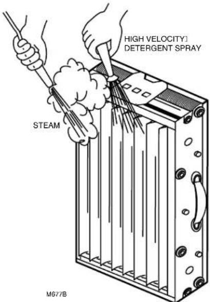
Cleaning the Cell Using High Velocity Water Pressure or Low Pressure Steam
Alternate methods can be used to clean some contaminants from the F90 cell. To prevent damage to prefilter, do not use these methods to clean the prefilter. See Fig. 15.
Water method—Be careful to avoid damage to the cell. If detergent is required, use an alkaline base detergent. Do not use an acid detergent. Aim water straight on or at a very slight angle when rinsing collector plate side of cell. This will minimize uneven spacing of collector plates caused by water pressure.
Steam method—Be extremely careful when steam cleaning to avoid warping or bending the collector plates of the cell. Remember that the cell will be hot after steam cleaning, and be extremely careful to avoid burns. Use only low pressure or wet steam.
NOTE: Assure the steam pressure is less than 5 psi (35 kPa) and steam temperature is less than 250°F (121°C).
Discolored Aluminum
After cleaning, the cell and prefilter occasionally look stained. If the stain is black or very dark, it is probably dirt residue. This can lower the F90 efficiency. Clean and rinse the cell and prefilter again.
If the stain is white, it is detergent residue. This lowers the F90 efficiency and can corrode the aluminum. Rinse the cell and prefilter again.
If the stain is tan, yellow, or a thin film, it is probably tobacco smoke or other airborne dirt. Moderate discoloration does not affect the F90 efficiency. Recleaning is not necessary.
Removing Specific Contaminants from the Cell
The following list gives the appropriate cleaning procedure for types of contamination often found on cells and prefilters. Cleaning procedures are listed in order of preference. Be careful not to bend cell blades.
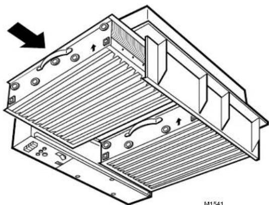
Reinstalling the Cell, Prefilter, and Activated Carbon Filter if Used
- Wipe off surface dirt inside and outside of the grille and cover.
- Replace the activated carbon filters with new filters if needs replacement. See Fig. 16.
- Inspect the cells for broken ionizer wires and bent collector plates. Bend moderately bent or warped collector plates back into shape. Replace broken ionizer wires replaced for top efficiency as instructed on page 15.
| Contaminant | Cleaning Procedure |
| Animal Hair | Dishwasher Detergent Solution |
| Carbo(carbonblack, soot, lamp black, graphite, charcoal dust, etc.) | Dishwasher Detergent SolutionHigh Pressure Water* |
| Cooking Oilsgebile, soybean, peanut, etc.) | Dishwasher Detergent Solution8am |
| ninal(lard, butter, etc.) | Dishwasher Detergent Solution |
| Cott nifer | Dishwasher Detergent Solution |
| Btu(silicon dioxie, calcium carbonate, and mineral type compounds) | Dishwasher Detergent Solution |
| Flour Dust | Dishwasher Detergent Solution |
| Mineral Oil(petroleum base, diesters and silicone) | Dishwasher Detergent Sol utio High Pressure Water* |
| Paper Products | Dishwasher Detergent Solution |
| aRt(Oil Base) | Dishwasher Detergent Solution |
| Water Base | Dishwasher Detergent Solution |
| Pine Tar Resins | Dishwasher Detergent Solution8am |
| Soaps | Dishwasher Detergent Solution |
| Sodium Chloride | Dishwasher Detergent Solution |
| uSar(includes molasses, etc.) | Dishwasher Detergent Solution8am |
| Talc | Dishwasher Detergent Solution |
| Tobacco Tars and Smoke | iShwasher Detergent Solution |
| Varnishes | Dishwasher Detergent Solution |
| aW(all types) | Dishwasher Detergent Solution8am |
* Method not appropriate for cleaning prefilter.
4. Carefully wipe ionizer wires to remove any remaining water deposits.
5. Assure cells are completely dry before reinstalling in the air cleaner. If cells are placed into the F90 while still wet, the cells may short out and arc frequently. Although the F90 will appear to be operating, the cells may not be cleaning during the drying period.
text_image
HIGH VELOCITY] DETERGENT SPRAY STEAM M677BFig. 15. Using high velocity water or steam to clean cells.
- Slide the cells into the channel guides until they touch the backstop of the F90. Assure the cell airflow arrow is pointing toward the fan. In this position, the ionizer wires are facing downward (away from the fan).
- Slide the prefilters into the channel guides until they touch the back of the channels.
- Swing the cover up until it closes, engaging the two latches. See Fig. 13.
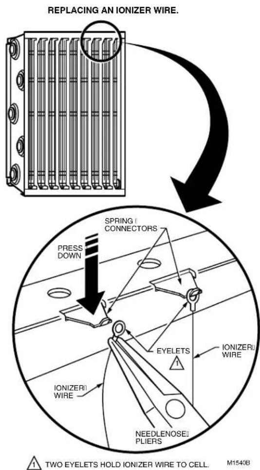
Replacing Ionizer Wires
Broken or bent ionizer wires can cause an electrical short to ground, often resulting in visible arcing or sparking. Do not use cells until broken wires are removed. Cells can be used temporarily with one wire missing, but replace the wire as soon as possible. Replacement wires are supplied cut to length with eyelets on both sides for easy installation. Order part no. 136434AA. To install:
- Hook the eyelet on one end of the wire over the spring connector on one end of the cell. See Fig. 17. Be careful to avoid damaging the spring connector or other parts of the cell.
- Hold the opposite eyelet with a needlenose pliers and stretch the wire the length of the cell. Depress the opposite spring connector and hook the eyelet over it.
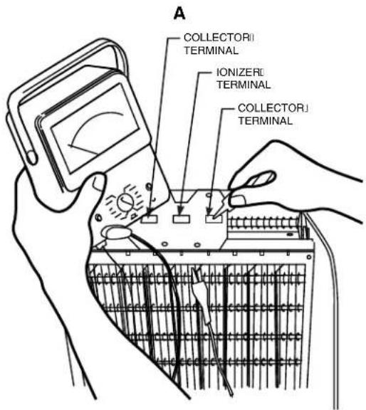
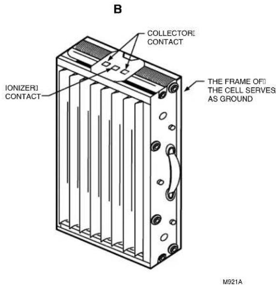
- Check the cell for short circuits using an ohmmeter. See Fig. 18. Check the resistance between the frame of the cell and both the ionizer and the collector contacts. In each case, the resistance should be infinite.
Modifying to Reduce Ozone Odor
In normal operation, the F90 generates a trace amount of ozone that is considerably under the limit prescribed by the U.S. Food and Drug Administration (FDA). During the first week or two of operation, the amount may be higher because of sharp edges on some of the new high voltage metal parts. Normal use dulls these edges in a short time.
natural_image
Technical line drawing of a mechanical assembly with ribbed internal structure and mounting brackets (no text or symbols)Fig. 16. Reinstalling F90 cells.
text_image
REPLACING AN IONIZER WIRE. PRESS DOWN SPRING | CONNECTORS IONIZER WIRE EYELETS IONIZER WIRE NEEDLENOSE PLIERS TWO EYELETS HOLD IONIZER WIRE TO CELL. M1540BFig. 17. Installing new ionizer wire.
A person with an average sense of smell can detect the odor of ozone indoors in concentrations as low as 0.003 part per million (ppm). OSHA workplace regulations permit up to 0.100 ppm ozone concentration. The F90 contributes 0.005 to 0.010 ppm of ozone to the indoor air. The U.S. FDA and Health and Welfare Canada recommend that indoor ozone concentration should not exceed 0.050 ppm. As a comparison, the outdoor ozone level in major cities is sometimes higher than 0.100 ppm.
If desired, the ozone generated by the F90 can be reduced in one of two ways:
• Install the optional activated carbon filters.
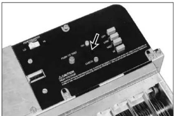
- Open the cover and move the F90 performance switch to the LO setting. Close the cover. With the switch in LO, the cleaning efficiency is reduced 5 to 15 percent, depending on airflow.
NOTE: The performance switch must be set solidly in either HI or LO position and not between, or the F90 may not function properly. See Fig. 19.
ELECTRICAL TROUBLESHOOTING

WARNING
Electrical Shock Hazard.
Can cause personal injury or equipment damage.
- Electrical troubleshooting must be performed by only qualified personnel.
- The following procedures expose hazardous levels of electrical current. Disconnect the power supply between checks and proceed carefully.
text_image
A COLLECTORI TERMINAL IONIZERI TERMINAL COLLECTORI TERMINALTools And Equipment
Troubleshooting the F90 requires:
- Needlenose pliers for stringing ionizer wires and inserting edge connectors.
• Test meter with 15 kVdc probe.
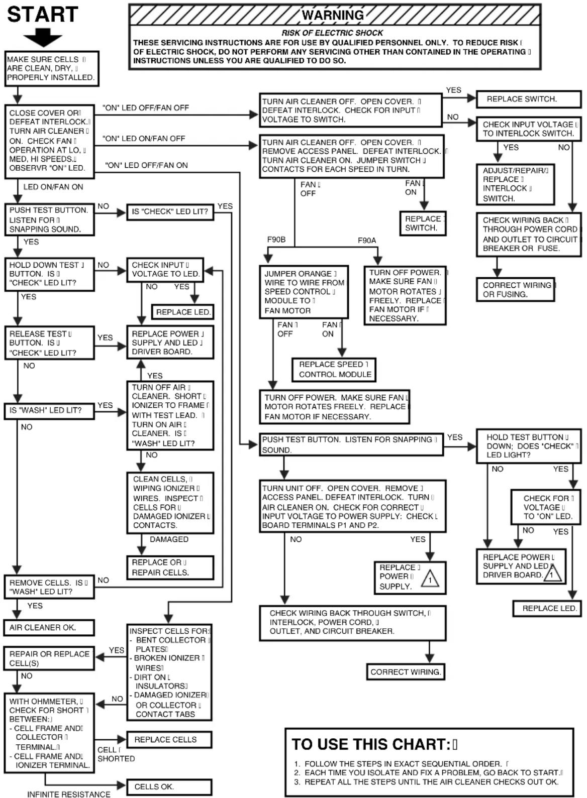
Troubleshooting Procedure
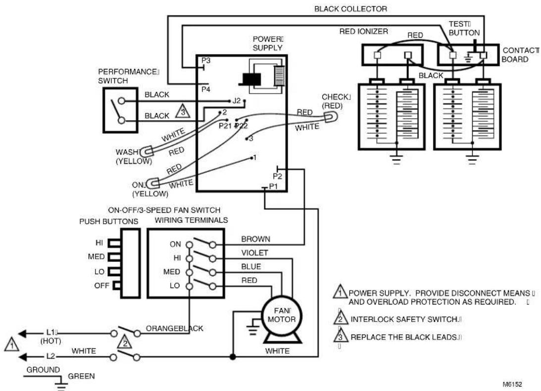
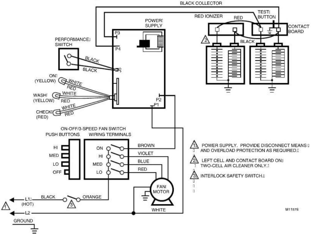
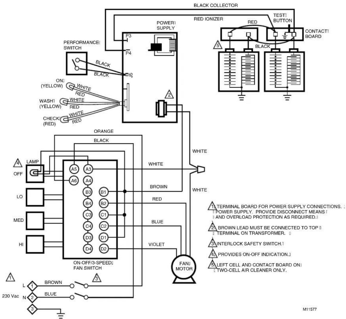
The F90 troubleshooting charts quickly isolate F90 problems. See Fig. 20. If removing power box, follow instructions below. See Fig. 21. For the F90 schematic diagrams, see Fig. 22 through 25.
Removing The Power Box
Open the power box and remove the power supply assembly as follows:
- Open the cover by pulling the two latches located on the front of the cover and swinging the cover down until it hangs. See Fig. 13.
- Remove the prefilter and the cell from the channel guide.
- Loosen the screws holding the power supply assembly cover plate and remove the cover plate. See Fig. 21.
text_image
B COLLECTORI CONTACT IONIZERI CONTACT THE FRAME OF THE CELL SERVES AS GROUND M921AFig. 18. Checking cells for short circuits.
- Loosen two screws on inner wall of power supply assembly and three screws on the top of the assembly. Slide the power supply assembly toward the center of the air cleaner and disconnect the two Molex connectors and the one quick disconnect. See Fig. 21.
- Remove the power supply assembly to a table or workbench.

Fig. 19. Setting performance switch in either HI or LO.
flowchart
graph TD
    A["START"] --> B["MAKE SURE CELLS || ARE CLEAN, DRY, || PROPERLY INSTALLED."]
    B --> C["CLOSE COVER OR DEFEAT INTERLOCK.|| TURN AIR CLEANER ON. CHECK FAN || OPERATION AT LO. || MED, HI SPEEDS.|| OBSERV R "ON" LED."]
    C --> D["LED ON/FAN ON"]
    D --> E["PUSH TEST BUTTON. LISTEN FOR || SNAPPING SOUND."]
    E --> F{YES}
    F -->|NO| G["IS "CHECK" LED LIT?"]
    F -->|YES| H["HOLD DOWN TEST J BUTTON. IS || "CHECK" LED LIT?"]
    H --> I{YES}
    I --> J["RELEASE TEST U BUTTON. IS || "CHECK" LED LIT?"]
    J --> K{NO}
    K -->|YES| L{YES}
    K -->|NO| M{NO}
    L --> N{YES}
    N --> O["IS "WASH" LED LIT?"]
    N --> P{NO}
    O --> Q["REMOVE CELLS. IS || "WASH" LED LIT?"]
    Q --> R["AIR CLEANER OK."]
    Q --> S["REPAIR OR REPLACE CELL(S)"]
    S --> T{NO}
    T --> U["WITH OHMMETER, || CHECK FOR SHORT | BETWEEN:|| - CELL FRAME AND || COLLECTOR || TERMINAL;|| - CELL FRAME AND || ONIZER TERMINAL."]
    U --> V["CELL SHORTED"]
    V --> W["INFINITE RESISTANCE"]

    C --> X[""ON" LED OFF/FAN OFF"]
    X --> Y["TURN AIR CLEANER OFF. OPEN COVER. || DEFEAT INTERLOCK. CHECK FOR INPUT || VOLTAGE TO SWITCH."]
    Y --> Z{YES}
    Z -->|NO| AA["REPLACE SWITCH."]
    Z --> AB{NO}
    AB --> AC["TURN AIR CLEANER OFF. OPEN COVER. || REMOVE ACCESS PANEL. DEFEAT INTERLOCK. TURN AIR CLEANER ON. JUMPER SWITCH || CONTACTS FOR EACH SPEED IN TURN."]
    AC --> AD["FAN OFF"]
    AD --> AE["REPLACE SWITCH."]
    AD --> AF["JUMPER ORANGE || WIRE TO WIRE FROM SPEED CONTROL || MODULE TO || FAN MOTOR"]
    AF --> AG["FAN OFF"]
    AG --> AH["REPLACE SPEED 1 CONTROL MODULE"]
    AH --> AI["TURN OFF POWER. MAKE SURE FAN || MOTOR ROTATES FREELY. REPLACE FAN MOTOR IF NECESSARY."]
    AI --> AJ["PUSH TEST BUTTON. LISTEN FOR SNAPPING 1 SOUND."]
    AJ --> AK{YES}
    AK -->|NO| AL["REPLACE POWER 1 POWER SUPPLY. 1"]
    AL --> AM{NO}
    AM -->|YES| AN["CHECK WIRING BACK THROUGH SWITCH, || INTERLOCK, POWER CORD, || OUTLET, AND CIRCUIT BREAKER."]
    AN --> AO["CORRECT WIRING."]

    C --> AP[""ON" LED ON/FAN OFF"]
    AP --> AQ["TURN AIR CLEANER OFF. OPEN COVER. || REMOVE ACCESS PANEL. DEFEAT INTERLOCK. TURN AIR CLEANER ON. JUMPER SWITCH || CONTACTS FOR EACH SPEED IN TURN."]
    AQ --> AR["FAN OFF"]
    AR --> AS["REPLACE SWITCH."]
    AS --> AT["CHECK INPUT VOLTAGE || TO INTERLOCK SWITCH."]
    AT --> AU{YES}
    AU -->|NO| AV["ADJUST/REPAIR || REPLACE 1 INTERLOCK 1 SWITCH."]
    AV --> AW["CHECK WIRING BACK 1 THROUGH POWER CORD AND OUTLET TO CIRCUIT BREAKER OR FUSE."]
    AW --> AX["CORRECT WIRING OR FUSING."]

    E --> AY["NO"]
    YA["YES"] --> AZ["REPLACE LED."]

    subgraph WARNING
        AA
        AB
        AC
        AD
        AE
        AF
        AG
        AH
        AI
        AJ
        AK
        AL
        AM
        AN
        AO
        AP
        AQ
        AR
        AS
        AT
        AU
        AV
        AW
        AX
        AZ
        AP
        AO
        AO
        AX
        AP
        AO
        AP
        AX
        AP
        AO
        AP
        AX
        AP
        AO
        AP
        AX
        AP
        AO
        AP
        AX
        AP
        AO
        AP
        AX
        AP
        AO
        AP
        AX
        AP
        AO
        AP
        AX
        AP
        AO
        AP
        AX
        AP
        AO
        AP
        AX & AO & AO & AO & AO & AO & AO & AO & AO & AO & AO & AO & AO & AO & AO & AO & AO & AO & AO & AO & AO & AO & AO & AO & AO & AO & AO & AO & AO & AO & AO & AO & AO & AO & AO & AO & AO & AO & AO & AO & AO & AO & AO & AO & AO & AO & AO & AO & AO & AO & AO &AOO
    end

    %% Legend

ELECTRONIC COMPONENTS ON POWER SUPPLY BOARDS ARE NOT FIELD REPLACEABLE. ATTEMPTED SERVICE WILL DAMAGE OF BOARDS. IF TROUBLESHOOTING INDICATES A POWER SUPPLY PROBLEM, REPLACE THE ENTIRE POWER SUPPLY ASSEMBLY.
M1525B
Fig. 20. F90 electrical troubleshooting procedure.
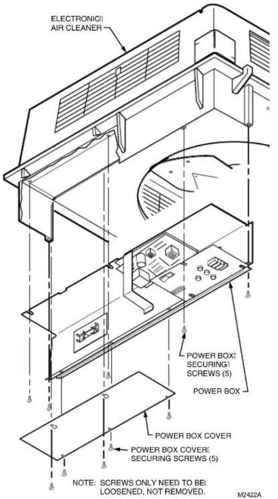
text_image
ELECTRONIC AIR CLEANER POWER BOX SECURING SCREWS (5) POWER BOX POWER BOX COVER POWER BOX COVER SECURING SCREWS (5) NOTE: SCREWS ONLY NEED TO BE LOOSENED, NOT REMOVED. M2422AFig. 21. Removing the F90 Power Box Assembly.
flowchart
graph TD
    A["PERFORMANCE SWITCH"] --> B["BLACK"]
    B --> C["WHITE"]
    C --> D["WASH (YELLOW)"]
    D --> E["RED"]
    E --> F["ON (YELLOW)"]
    F --> G["WHITE"]
    G --> H["P21 #22"]
    H --> I["P1"]
    I --> J["P3"]
    J --> K["P4"]
    K --> L["POWER SUPPLY"]
    L --> M["P3"]
    M --> N["J2"]
    N --> O["CHECK (RED)"]
    O --> P["TEST BUTTON"]
    P --> Q["CONTACT BOARD"]
    Q --> R["BACK"]
    R --> S["ORANGE BLACK"]
    S --> T["FANI MOTOR"]
    T --> U["WHITE"]
    U --> V["ORANGE BLACK"]
    V --> W["L10 (HOT)"]
    V --> X["L2"]
    Y["POWER SUPPLY. PROVIDE DISCONNECT MEANS U AND OVERLOAD PROTECTION AS REQUIRED."] --> Z["INTERLOCK SAFETY SWITCH"]
    Z --> AA["REPLACE THE BLACK LEADS."]
    AB["GROUND GREEN"] --> AC["Ground"]
Fig. 22. F90A 120 Vac model schematic diagram.
text_image
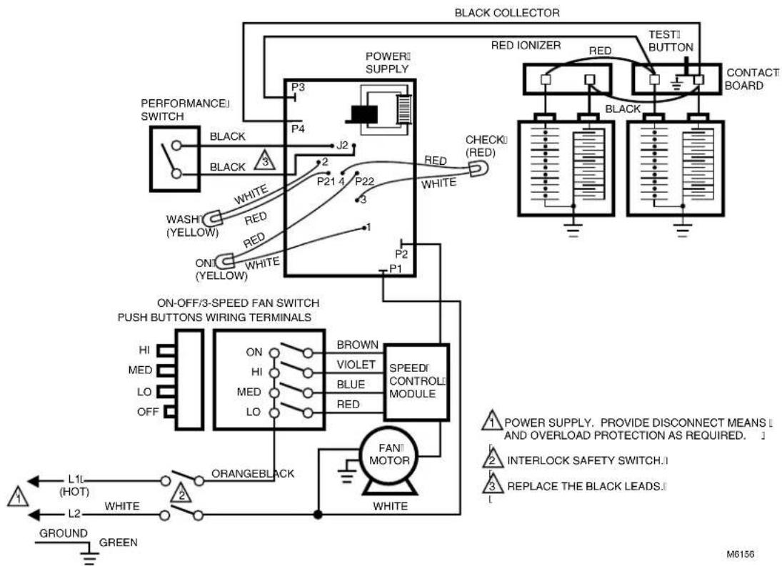
BLACK COLLECTOR POWER SUPPLY P3 P4 PERFORMANCE SWITCH BLACK BLACK ON1 (YELLOW) WHITE RED WASHI (YELLOW) WHITE RED CHECKI (RED) WHITE RED P2 P1 RED IONIZER RED TESTI BUTTON CONTACT BOARD 2 BLACK ON-OFF/3-SPEED FAN SWITCH PUSH BUTTONS WIRING TERMINALS BROWN VIOLET HI MED LO OFF ON HI MED LO BLUE RED FANI MOTOR WHITE L10 (HOT) BLACK ORANGE L2 GROUND M11576Fig. 23. F90A 120 Vac model schematic diagram.
flowchart
graph TD
    A["PERFORMANCE SWITCH"] --> B["ORANGE BLACK"]
    B --> C["ON/OFF/3-SPEED FAN SWITCH"]
    C --> D["FANJ MOTOR"]
    D --> E["TESTI BUTTON"]
    E --> F["CONTACTI BOARD"]
    subgraph Black Collector
        G["P3"] --> H["P4"]
        I["P3"] --> J["POWER SUPPLY"]
        K["P3"] --> L["RED IONIZER"]
        M["P3"] --> N["TESTI BUTTON"]
        O["P3"] --> P["CONTACTI BOARD"]
    end
    style Black Collector fill:#f9f,stroke:#333
    style TestI Button fill:#ccf,stroke:#333
    style ContactBoard fill:#cfc,stroke:#333
    style Orange fill:#fcc,stroke:#333
    style White fill:#ffc,stroke:#333
    style Blue fill:#fcc,stroke:#333
    style VIOLET fill:#fcc,stroke:#333
    style DarkBlue fill:#fcc,stroke:#333
    style LightBlue fill:#fcc,stroke:#333
    style GreenBlue fill:#fcc,stroke:#333
    style BlueRed fill:#fcc,stroke:#333
    style WhiteRed fill:#fcc,stroke:#333
    style DarkRed fill:#fcc,stroke:#333
    style GreenRed fill:#fcc,stroke:#333
    style BlueBlue fill:#fcc,stroke:#333
    style WhiteBlue fill:#fcc,stroke:#333
    style DarkBlue fill:#fcc,stroke:#333
    style GreenBlue fill:#fcc,stroke:#333
Fig. 24. F90A 230 Vac model schematic diagram (CE compliant model).
flowchart
graph TD
    A["BLACK COLLECTOR"] --> B["POWER SUPPLY"]
    B --> C["P3"]
    B --> D["P4"]
    B --> E["P21 4"]
    B --> F["P22"]
    B --> G["P2"]
    B --> H["P1"]
    B --> I["RED ONIZER"]
    B --> J["TEST BUTTON"]
    B --> K["CONTACT BOARD"]
    B --> L["WHITE RED"]
    B --> M["WHITE RED"]
    B --> N["WASH (YELLOW)"]
    B --> O["WHITE (YELLOW)"]
    B --> P["ON/OFF/3-SPEED FAN SWITCH PUSH BUTTONS WIRING TERMINALS"]
    P --> Q["HI MED LO OFF"]
    P --> R["ON HI MED LO"]
    P --> S["BROWN VIOLET BLUE RED SPEED CONTROL MODULE"]
    S --> T["FAN MOTOR"]
    T --> U["ORANGEBLACK"]
    U --> V["L1L (HOT) L2"]
    U --> W["GREEN"]
    X["POWER SUPPLY"] --> Y["INTERLOCK SAFETY SWITCH"]
    Y --> Z["REPLACE THE BLACK LEADS"]
    style A fill:#f9f,stroke:#333
    style B fill:#ccf,stroke:#333
    style C fill:#cfc,stroke:#333
    style D fill:#fcc,stroke:#333
    style E fill:#cff,stroke:#333
    style F fill:#ffc,stroke:#333
    style G fill:#fcc,stroke:#333
    style H fill:#fcc,stroke:#333
    style I fill:#fcc,stroke:#333
    style J fill:#fcc,stroke:#333
    style K fill:#fcc,stroke:#333
    style L fill:#fcc,stroke:#333
    style M fill:#fcc,stroke:#333
    style N fill:#fcc,stroke:#333
    style O fill:#fcc,stroke:#333
    style P fill:#fff,stroke:#333
    style Q fill:#fff,stroke:#333
    style R fill:#fff,stroke:#333
    style S fill:#fff,stroke:#333
    style T fill:#fff,stroke:#333
    style U fill:#fff,stroke:#333
    style V fill:#fff,stroke:#333
    style W fill:#fff,stroke:#333
    style X fill:#fff,stroke:#333
    style Y fill:#fff,stroke:#333
    style Z fill:#fff,stroke:#333
Fig. 25. F90B 120 Vac model schematic diagram.
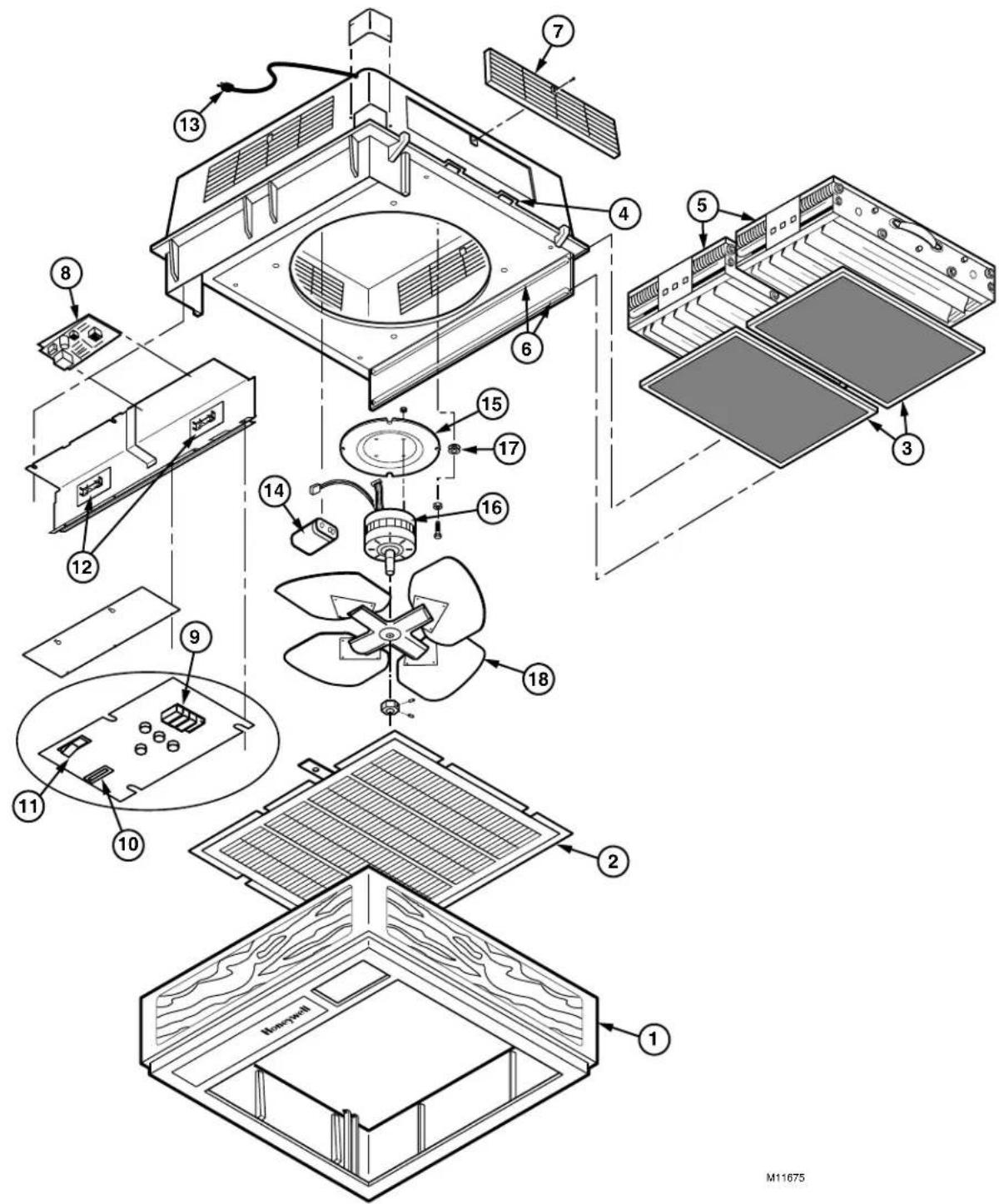
REPLACEMENT PARTS LIST/EXPLODED VIEW
See Fig. 26 for exploded view.
| .on | no | rebmuNtraP | |
| F90A i zH | F90Å 06210/230/240 Vac, 50 Hz | ||
| 1 | Cover Assembly (includes inlet grille) Woodgrain with blac kinh ayG | A9202 B9202 | A9202 B9202 |
| 2 | Inlet Grille Woodgrain with black trim ayG | 703202 803202 | 202307 803202 |
| 3 | Prefilter (20 x 12-1/2) | 202289 (2) | 202289 (2) |
| 4 | atch Woodgrain with black trim ayG | )2(91)2(02) | 6202 2026 2(91)2(026202) |
| 5 | Heavy Duty Commercial Cell (4-1/2 x )0221 | )2 | (0301B73CF) |
| 6 | Filter Rail (pre- and post-filter) | 202300 (4) | 202300 (4) |
| 7 | Outlet Louvers Woodgrain with black trim ayG | egraL 4(3) 4(4) | 3202 3202 18202 |
| 8 | Solid State Power Supply | 208427D | 208427S |
| 9 | Four-Position Control Switch | 190382 | 190382 |
| 10 | Interlock Switch | 197929 | 197929 |
| 11 | Performance Switch | 196214 | 196214 |
| 12 | Contact Board Assembly | 138889A (2) | 138889A (2) |
| 13 | Power Cord | 4047EQZ | 4074ERR |
| 14 | Motor Capacitor | 202281 | 203433 |
| 15 | Motor Mounting Plate/Grille | 202311 | 202311 |
| 16 | Motor (does not include mounting plates or grommets) | 202 A8 | 8C |
| 17 | Rubber Grommets (package of 4) | 4074EQP | 4074EQP |
| 18 | Fan | 202280 | 202280 |
Parts and Optional Accessories Not Illustrated
| oitpcBe | Part Number | |
| BA120 Vac, 60 Hz | BA220/240 Vac, 50 Hz | |
| Hard Wired Remote Control Assembly | 190097B | 190097B |
| Ionizer Wires (package f)5 | 136434AA | 136434AA |
| Blank Plate for Discharge Grille | 202613 | 202613 |
| Wall Mounting Kit (blank plate provided) | 118636C | 118636C |
| Ceiling Mount Kit | 4074EAB | 4074EAB |
| Carbon Filter 1/2 x 20 x 12-1/2 inches(13 x 508 x 318 mm) | 202614 (2) | 072) |
p
i
2)0301B
7
text_image
Exploded view diagram of a solar panel assembly with numbered components for identification and assembly.Fig. 26. F90A exploded view. Part numbers are keyed to Parts List.
LIMITED ONE-YEAR WARRANTY
Air-Pure Systems warrants its air cleaner products to be free from defects in workmanship or materials under normal use and service, for a period of one (1) year from the date of purchase by the original end-user. If at anytime during the warranty period the product is defective or malfunctions, Air-Pure Systems, through the distributor or dealer, from which the product was purchased, or through an authorized warranty repair station, shall at Air-Pure Systems option, replace or repair the defective product or component.
This warranty does not cover removal or installation costs. This warranty shall not apply if it is shown that the defect or malfunction was caused by damage which occurred during handling or shipment, improper electrical connections, improper use of the product or abuse.
Air-Pure Systems sole responsibility shall be to repair or replace the product within the terms stated above. AIR-PURE SYSTEMS SHALL NOT BE LIABLE FOR ANY LOSS OR DAMAGE OF ANY KIND, INCLUDING ANY INCIDENTAL OR CONSEQUENTIAL DAMAGES RESULTING, DIRECTLY OR INDIRECTLY, FROM ANY BREACH OF WARRANTY, EXPRESS OR IMPLIED, OR ANY OTHER FAILURE OF THIS PRODUCT. (Some states do not allow the exclusion or limitation or incidental or consequential damages, so this limitation may not apply to you.). THE WARRANTIES SET FORTH HEREIN ARE EXCLUSIVE AND AIR-PURE SYSTEMS EXPRESSLY DISCLAIMS ALL OTHER WARRANTIES, WHETHER WRITTEN OR ORAL, IMPLIED OR STATUTORY, INCLUDING BUT NOT LIMITED TO ANY WARRANTIES OR MERCHANTABILITY, WORKMANSHIP, OR FITNESS FOR A PARTICULAR USE.
This warranty gives you specific legal rights and you may have other rights which vary from state to state.
How to make a warranty claim or have questions answered:
Should you have a warranty claim or questions about the warranty policy, contact the distributor or dealer from which you purchased the product or the authorized warranty repair stations nearest your location.
NOTE: Do not return any products or parts to the factory without a factory issued "Return Warranty Good Label" issued by Air-Pure Systems.
In the event you or other persons, have any questions concerning the use and care of this product of this warranty please call or write the factory.
Air-Pure Systems
16873 Fish Point Rd. SE
Prior Lake, MN 55372-1714
Phone: (800) 998-1919