
VYC 100P - Digital decoder Extron - Free user manual and instructions
Find the device manual for free VYC 100P Extron in PDF.


| Product Type | Digital Decoder / Video Scaler |
| Brand | Extron |
| Model | VYC 100P |
| Dimensions (H x W x D) | 1.7 x 17.5 x 10.5 inches (4.3 x 44.5 x 26.7 cm) |
| Weight | 5.5 lbs (2.5 kg) |
| Power Supply | 100-240 VAC, 50/60 Hz, internal |
| Power Consumption | 30 Watts |
| Video Inputs | 1x HDMI, 1x VGA, 1x Composite |
| Video Outputs | 1x HDMI, 1x VGA |
| Audio Inputs | 1x Stereo RCA, 1x 3.5mm |
| Audio Outputs | 1x Stereo RCA, 1x 3.5mm |
| Maximum Resolutions | Up to 1920x1200 (VGA) and 4K (HDMI) |
| Supported Video Standards | NTSC, PAL, SECAM |
| Control Interface | RS-232, Ethernet, USB |
| Front Panel Controls | Buttons for menu, input select, and power |
| Indicators | Power, input signal, and output signal LEDs |
| Operating Temperature | 32°F to 122°F (0°C to 50°C) |
| Cooling | Fanless, convection cooled |
| Product Family | VYC Series |
| Warranty | 3 years parts and labor |
| Included Accessories | Power cord, user manual, rack ears |
Frequently Asked Questions - VYC 100P Extron
User questions about VYC 100P Extron
0 question about this device. Answer the ones you know or ask your own.
Ask a new question about this device
Download the instructions for your Digital decoder in PDF format for free! Find your manual VYC 100P - Extron and take your electronic device back in hand. On this page are published all the documents necessary for the use of your device. VYC 100P by Extron.
USER MANUAL VYC 100P Extron
Extron. Electronics INTERFACING, SWITCHING AND DISTRIBUTION

User's Manual
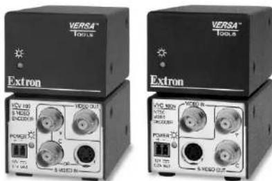
YCV 100 S-Video Encoder
VYC 100N and VYC 100P Composite Video Decoder
| Extron USA - West Headquarters | Extron USA - East | Extron EMEA | Extron Asia | Extron Japan | Extron China | Extron Middle East |
| +400,853,9178 | +600,833,8174 | +100,3937,6673 | +991,7309,6766 | +113,3811,7655 | +100,883,1066 | +971,4299,100 |
| Bosha, 24, Canada | Bosha, 24, Canada | Bosha, 24, Canada | Bosha, 24, Canada | Bosha, 24, Canada | Bosha, 24, Canada | +671,4290,000,743 |
| +174,491,9166 | +174,491,9166 | +174,491,9166 | +174,491,9166 | +174,491,9166 | +174,491,9166 | +174,491,9166 |
| +174,491,9167,734 | +174,491,9167,734 | +174,491,9167,734 | +174,491,9167,734 | +174,491,9167,734 | +174,491,9167,734 | +174,491.7347,734 |
© 2008 Extron Electronics. All rights reserved.
68-779-01 Rev. C 08 08
Precautions
Safety Instructions • English

This symbol is intended to alert the user of important operating and maintenance (servicing) instructions in the literature provided with the equipment.

This symbol is intended to alert the user of the presence of uninsulated dangerous voltage within the product's enclosure that may present a risk of electric shock.
Caution
Read instructions • Read and understand all safety and operating instructions before using the equipment
situations making the equipment
Retain Instructions • The safety instructions should be lost for future references.
Eolten Warm
The following: 1. All the functions and variables are not available in the context of the acquisition.
Avail Attachments & (2) rec. vortiva en
recommendability the equipment manufacture, by not they may be
Hearlou.
Power Apheres * This equipment should be opened only from the power source indicated on the power. This equipment is intended to be used with a real power system with a grounded (neutral) conductor. The third (grounding) pin is a safety fixture, but not enough to be any other bit.
Power disconnection. To remove power from, for equipment soldly, remove all power cards from the rear of the equipment, or the develop power module (or detectable), or from the power source receptacle wall point.
Power and protection * Power cards should be routed, or that they are not likely to be stopped on or placed by home stored upon or against them.
Servicing • lateral something to qualified service personnel. There are no use of services like this parts inside. If prevent the risk of shock, do not attempt to service this equipment your own function upon in meeting cases may expose you to dangerous village or other hazards.
Slots and openings * If the equipment has slots or holes in the enclosure, there are provided to prevent overcoating of sensitive components inside. These opening issues never be blocked by other projects.
Lithium battery + 1 from > a danger of explosion if battery is increasingly replaced. So place it only with the source equivalent to recommended by the manufacturer. Dispersed used batteries according to the manufacturer's training.
Avertissement
Extron Electronics warrants this product against defects in materials and workmanship for a period of three years from the date of purchase. In the event of malfunction during the warranty period attributable directly to faulty workmanship and/or materials, Extron Electronics will, at its option, repair or replace said products or components, to whatever extent it shall deem necessary to restore said product to proper operating condition, provided that it is returned within the warranty period, with proof of purchase and description of malfunction to:
USA, Canada, South America, Europe, Africa, and the Middle East: and Central America; Extron Electronics, Europe
Extron Electronics Beeldschermweg 6C
1001 East Ball Road 3821 AII Amersfoort
Anaheim, CA 92805, USA The Netherlands
Asia: Japan:
Extron Electronics, Asia Extron Electronics, Japan
135 Joo Seng Road, #04-01 Kyodo Building PM Industrial Bldg. 16 Ichibancho
Singapore 368363 Chiyoda-ku, Tokyo 102-0082
Japan
This Limited Warranty does not apply if the fault has been caused by misuse, improper handling care, electrical or mechanical abuse, abnormal operating conditions or non-Extron authorized modification to the product.
If it has been determined that the product is defective, please call Extron and ask for an Applicatious Engineer at (714) 491-1500 (USA), 31.33.453.4040 (Europe), 65.6383.4400 (Asia), or 81.3.3511.7655 (Japan) to receive an RA# (Return Authorization number). This will begin the repair process as quickly as possible.
Units must be returned insured, with shipping charges prepaid. If not insured, you assume the risk of loss or damage during shipment. Returned units must include the serial number and a description of the problem, as well as the name of the person to contact in case there are any questions.
Extron Electronics makes no further warranties either expressed or implied with respect to the product and its quality, performance, merchantability, or fitness for any particular use. In no event will Extron Electronics be liable for direct, indirect, or consequential damages resulting from any defect in this product even if Extron Electronics has been advised of such damage.
Please note that laws vary from state to state and country to country, and that some provisions of this warranty may not apply to you.
安全须知 · 中文

This equipment has been tested and found to comply with the limits for a Class A digital device, pursuant to part 15 of the FCC Rules. These limits are designed to provide reasonable protection against harmful interference when the equipment is operated in a commercial environment. This equipment generates, uses and can radiate radio frequency energy and, if not installed and used in accordance with the instruction manual, may cause harmful interference to radio communications. Operation of this equipment in a residential area is likely to cause harmful interference, in which case the user will be required to correct the interference at his own expense.
NOTE This unit was tested with shielded cables on the peripheral devices. Shielded cables must be used with the unit to ensure compliance.
Table of Contents
Chapter 1 • Introduction....1-1
About the YCV 100, VYC 100N, and VYC 100P ..... 1-2
Features 1-2
Chapter 2 • Installation and Operation.... 2-1
Mounting the YCV 100, VYC 100N and VYC 100P . 2-2
Tabletop use 2-2
UL rack mounting guidelines 2-2
Rack mounting 2-3
Back of the rack installation.... 2-4
Furniture mounting 2-5
Projector mounting 2-6
Front Panel Features 2-6
Rear Panel Features and Cabling 2-7
YCV 100 2-7
VYC 100N and VYC 100P 2-8
Troubleshooting 2-10
Appendix A • Specifications, Part Numbers,
and Accessories ...... A-1
Specifications A-2
Included Parts A-4
Optional Accessories...... A-4
All trademarks mentioned in this manual are the properties of their respective owners.
68-779-01 Rev. C
08 08
Table of Contents, cont'd

YCV 100, VYC 100N, and VYC 100P
1 Chapter One
Introduction
About the YCV 100, VYC 100N and VYC 100P
Features
Introduction
About the YCV 100, VYC 100N, and VYC 100P
The Extron YCV 100 is a high-performance S-video to composite video encoder. It combines S-video Y and C (luminance and chrominance) signals into a composite video signal. The encoder is compatible with NTSC 3.58, NTSC 4.43, PAL, and SECAM signals. The unit accepts S-video input on two female BNC connectors or one 4-pin mini DIN connector and outputs composite video on one female BNC connector.
The Extron VYC 100N and VYC 100P are composite video to S-video decoders. It separates a composite video signal into S-video Y and C signals. The VYC 100N decodes NTSC 3.58 signals only and the VYC 100P decodes PAL signals only. Both decoders accept composite video input on one female BNC connector and outputs S-video signals on two female BNC connectors and/or one 4-pin mini DIN connector.
All units include an external 12 V power supply that accepts 100-240 VAC 50/60 Hz input.
Features
Furniture, projector, and rack mountability — The YCV 100, VYC 100N, and VYC 100P can be mounted under a desk, podium, or other furniture, or secured to a projector mount with optional brackets. Alternatively, they can be mounted on an optional VersaTools ^ or universal rack shelf.
Versatile S-video input/output configuration — The encoder and decoder can pass S-video signals via two female BNC connectors or one 4-pin mini DIN connector.
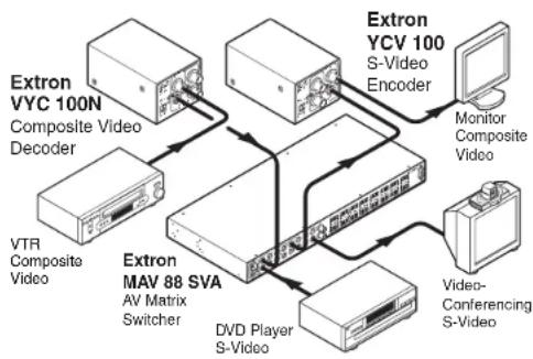
flowchart
graph TD
    A["Extron VYC 100N\nComposite Video Decoder"] --> B["Extron MV 88 SVA\nAV Matrix\nSwitcher"]
    C["VTR Composite Video"] --> B
    D["DVD Player S-Video"] --> B
    E["Extron YCV 100\nS-Video Encoder"] --> F["Monitor Composite Video"]
    G["Video-Conferencing S-Video"] --> H["Video"]
    B --> I["Extron MV 88 SVA\nAV Matrix\nSwitcher"]
    B --> J["DVD Player S-Video"]

YCV 100, VYC 100N, and VYC 100P

Installation and Operation
Mounting the YCV 100, VYC 100N, and VYC 100P
Front Panel Features
Rear Panel Features and Cabling
Troubleshooting
Installation and Operation
Mounting the YCV 100, VYC 100N, & VYC 100P
The YCV 100, VYCN, and VYC 100P can be set on a table or mounted on a rack shelf, under a desk or tabletop, or on a projector mount.
Tabletop use
Four self-adhesive rubber feet are included with the YCV 100, VYC 100N, and VYC 100P. For tabletop use, attach one foot at each corner of the bottom side of the unit and place the unit in the desired location.
UL rack mounting guidelines
The following Underwriters Laboratories (UL) guidelines pertain to the safe installation of the YCV 100, VYC 100N, and VYC 100P in a rack.
- Elevated operating ambient temperature — If installed in a closed or multi-unit rack assembly, the operating ambient temperature of the rack environment may be greater than room ambient temperature. Therefore, install the unit in an environment compatible with the maximum ambient temperature (Tma = +122 °F, +50 °C) specified by Extron.
- Reduced air flow — Install the equipment in a rack so that the amount of air flow required for safe operation of the equipment is not compromised.
- Mechanical loading — Mount the equipment in the rack so that a hazardous condition is not achieved due to uneven mechanical loading.
- Circuit overloading — Connect the equipment to the supply circuit and consider the effect that circuit overloading might have on overcurrent protection and supply wiring. Appropriate consideration of equipment nameplate ratings should be used when addressing this concern.
- Reliable earthing (grounding) — Maintain reliable grounding of rack-mounted equipment. Pay particular attention to supply connections other than direct connections to the branch circuit (e.g. use of power strips).
Rack mounting
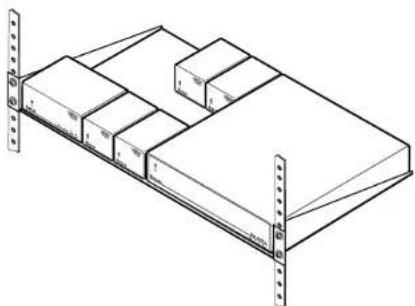
For optional rack mounting, do not install the rubber feet. Mount the YCV 100, VYC 100N, or YCV 100P, on a VersaTools ^8 rack shelf (RSF 123, Extron part #60-190-20; RSB 123, part #60-604-21), or on a 6" deep rack shelf (RSU 126, part #60-190-10; RSB 126, part #60-604-11), or on a 1U universal rack shelf (RSU 129, part #60-190-01; RSB 129, #60-604-02).
On the standard rack shelf, the YCV 100, VYC 100N, and VYC 100P mount in one of eight locations to the rear of the shelf or in one of eight locations to the front of the shelf.
- Remove rubber feet if they were previously installed on the bottom of the unit.
- Mount the unit on the rack shelf, using two 4-40 x 3/16" screws in opposite (diagonal) corners to secure the unit to the shelf.
- Install blank panel(s) or other unit(s) on the rack shelf.
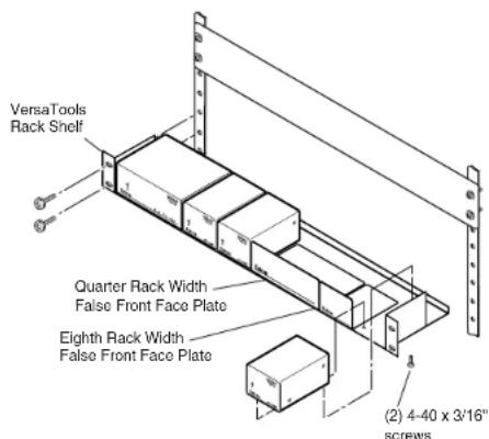
Mounting the YCV 100, VYC 100N, and VYC 100P on a VersaTools rack shelf
Installation and Operation
natural_image
Isometric line drawing of a multi-level storage unit with numbered compartments (no text or symbols)Mounting the YCV 100, VYC 100N, and VYC 100P on a 1U standard rack shelf
Back of the rack installation
The YCV 100, VYC 100N, and VYC 100P can be conveniently mounted on the rear of a rack by using the Extron back of the rack mounting kit (MBB 100, Extron part #70-367-01). The back-of-the-rack mounting kit allows the device to be vertically positioned.
- Attach the two back of the rack mounting brackets to the sides of the unit using the four included mounting screws.
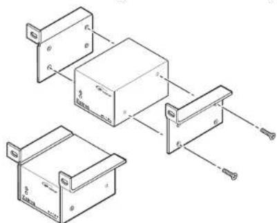
- Mount the unit on the rack using the two included rack screws. It can be vertically mounted facing in either direction, as shown here.
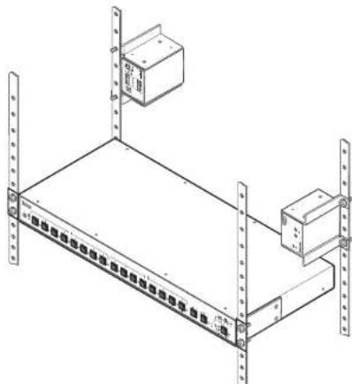
natural_image
Isometric line drawing of a server rack with two labeled boxes and vertical supports (no text or symbols)Furniture mounting
Furniture mount the YCV 100, VYC 100N, or VYC 100P using the optional MBU 123 mounting kit (part #70-212-01) as follows:
- Remove rubber feet if they were previously installed on the bottom of the unit.
- Attach the furniture mounting brackets to the unit with the machine screws provided.
- Hold the unit with the attached brackets against the underside of the table or other furniture. Mark the location of the screw holes of the bracket on the mounting surface.
- Drill 3/32" (2 mm) diameter pilot holes, 1/4" (6.3 mm) deep in the mounting surface at the marked screw locations.
- Insert #8 wood screws into the four pilot holes. Tighten each screw into the mounting surface until just less than 1/4" of the screw protrudes.
- Align the mounting screws with the slots in the brackets and place the unit against the surface, with the screws through the bracket slots. See the illustration below.
- Slide the unit slightly forward or back, then tighten all four screws to secure the unit in place.
Installation and Operation, cont'd
Projector mounting
Projector mount the YCV 100, VYC 100N, or VYC 100P using the optional PMK 100 mounting kit (part #70-217-01) as follows:
- Remove rubber feet if they were previously installed on the bottom of the unit.
- Attach the projector mounting brackets to the unit with the machine screws provided.
- Secure the unit below the ceiling to a projector mount or other surface by inserting the mounting bolt through the bracket's slotted hole, as shown below.
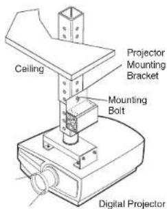
Mounting the YCV 100, VYC 100N, and VYC 100N on a projector mount
Front Panel Features
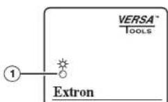
① Power LED — Lights to indicate that the YCV 100/VYC 100N/VYC 100P is on.
Rear Panel Features and Cabling
YCV 100
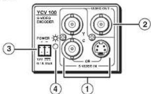
① Input connectors — Connect an S-video source to either:
• the two female BNC connectors or
• the 4-pin mini DIN connector.
NOTE Do not connect S-video sources to both types of connectors at the same time.
② Output connector — Connect a composite video output device to this female BNC connector.
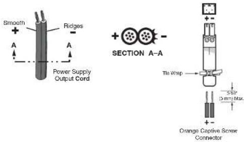
③ Power connector — An external 12 V power supply is included with the unit. Plug it into this 2-pole captive screw connector. Wire the connector as shown below.
CAUTION
When connecting the power supply, voltage polarity is extremely important. Applying power with incorrect voltage polarity could damage the power supply and the YCV 100. Identify the power cord negative lead by the ridges on the side of the cord or a black heat shrink wrapping around it.
Installation and Operation, cont'd
NOTE
Strip the insulation from the wires to expose 5 mm (3/16") of the conductors. Do not tin the stripped power supply leads before installing the captive screw connector. Tinned wires are not as secure in the captive screw connectors and could be pulled out.
WARNING
The two power cord wires must be kept separate while the power supply is plugged in. Remove power before wiring.
To verify the polarity before connection, check the no load power supply output with a voltmeter.

Power LED — Lights to indicate that the YCV 100 is on.
VYC 100N and VYC 100P
NOTE
The VYC 100N and VYC 100P have identical rear panel connectors.
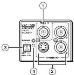
① Input connector — Connect a composite video source to this female BNC connector.
② Output connectors — Connect an S-video output device to:
• the two female BNC connectors and/or
③ Power connector — An external 12 V power supply is included with the unit. Plug it into this 2-pole captive screw connector. Wire the connector as shown in the following illustration.
CAUTION
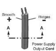
When connecting the power supply, voltage polarity is extremely important. Applying power with incorrect voltage polarity could damage the power supply and the VYC 100N/VYC 100P. Identify the power cord negative lead by the ridges on the side of the cord or a black heat shrink wrapping around it.
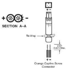
NOTE
Strip the insulation from the wires to expose 5 mm (3/16") of the conductors. Do not tin the stripped power supply leads before installing the captive screw connector. Tinned wires are not as secure in the captive screw connectors and could be pulled out.
WARNING
The two power cord wires must be kept separate while the power supply is plugged in. Remove power before wiring.
To verify the polarity before connection, check the no load power supply output with a voltmeter.
④ Power LED — Lights to indicate that the VYC 100N/VYC 100P is on.
Installation and Operation, cont'd
Troubleshooting
Possible problems and their solutions include the following:
- Problem: No power at unit
Solution: Verify that the unit is receiving power by checking the front or rear LED. If no LED is lit, check the DC power plug termination and polarity.
- Problem: No video input
Solution: Verify that the source and output devices are powered on and connected properly.
- Problem: Some chroma crawl on the vertical edges or a rainbow effect on some images
Solution: This is a normal characteristic of the unit.

YCV 100, VYC 100N, and VYC 100P

Specifications, Part Numbers, and Accessories
Specifications
Included Parts
Optional Accessories
Specifications, Part Numbers, and Accessories
Video
Gain Unity
Bandwidth
YCV 100 8 MHz (-3 dB)
VYC 100N, VYC 100P ..... 5.5 MHz (-5.5 dB)
Video input
Number/signal type
YCV 100 1 S-video
VYC 100N, VYC 100P ..... 1 composite video
Connectors
YCV 100 ...... 2 female BNC or 1 female 4-pin mini DIN
VYC 100N, VYC 100P ..... 1 female BNC
Nominal level 1 Vp-p for Y of S-video, and for composite
video
0.3 Vp-p for C of S-video
Minimum/maximum levels
S-video ...... Analog: 0.3 V to 1.5 Vp-p for Y
Composite video ...... Analog: 0.3 V to 1.5 Vp-p with no offset
Impedance 75 ohms
Return loss ...... -35 dB @ 5 MHz
DC offset (max. allowable) ..... 5 V
Video output
Number/signal type
YCV 100 1 composite video
VYC 100N, VYC 100P ..... 2 S-video
Connectors
YCV 100 ...... 1 female BNC
VYC 100N, VYC 100P ..... 2 female BNCs or (1) 4-pin mini DIN
Nominal level 1 Vp-p for Y of S-video and for composite
video
0.3 Vp-p for C of S-video
Minimum/maximum levels ..... 0.3 V to 1.5 Vp-p for Y of S-video or
composite video (follows input)
Impedance 75 ohms
Return loss ...... -40 dB @ 5 MHz
DC offset .... ±5 mV maximum with input at 0 offset
Sync
Standards
VYC 100N ..... NTSC 3.58
VYC 100P PAL
YCV 100....NTSC 3.58, NTSC 4.43, PAL, SECAM
General
External power supply .... 100 VAC to 240 VAC, 50/60 Hz, external, autoswitchable; to 12 VDC, 1 A (max.), regulated
Power input requirements
VYC 100N, VYC 100P ..... 12 VDC, 0.2 A
YCV 100 12 VDC, 0.1 A
Temperature/humidity ...... Storage: -40 to +158 °F (-40 to +70 °C) /
10% to 90%, noncondensing
Operating: +32 to +122 °F (0 to +50 °C) /
10% to 90%, noncondensing
Rack mount .... Yes, with optional 1U, 9.5" deep rack
shelf, part #60-190-01 (RSU 129) or
60-604-01 (RSB 129); or VersaTools ^3 3.5"
deep rack shelf, part #60-190-20 (RSF 123)
or 60-604-21 (RSB 123)
Furniture mountable with optional mini
under-desk mounting kit, part #70-212-01
(MBU 123)
Attachable to a projector mount with
optional mounting kit, part #70-217-01
(PMK 100)
Enclosure type ...... Metal
Enclosure dimensions 1.7" H x 2.2" W x 3.0" D
(1U high, one eighth rack wide)
(4.3 cm H x 5.6 cm W x 7.6 cm D)
(Depth excludes connectors.)
Product weight 0.4 lbs (0.2 kg)
Shipping weight 1 lbs (1 kg)
Vibration ISTA 1A in carton (International Safe
Transit Association)
Listings UL, CUL
Compliances ...... CE, FCC Class A, VCCI, AS/NZS, ICES
MTBF 30,000 hours
Warranty 3 years parts and labor
NOTE All nominal levels are at ±10%.
NOTE Specifications are subject to change without notice.
Specifications, Part Numbers, Accessories, cont'd
Included Parts
These items are included in each order for a YCV 100, VYC 100N, or VYC 100P:
| Included parts part number | Replacement |
| YCV 100 60-559-01 | |
| or VYC 100N 60-558-02 | |
| or VYC 100P 60-558-03 | |
| 12 VDC, 1 A external power supply 70-055-01 | |
| IEC power cord | |
| 3.5 mm, 2-pole captive screw connector | |
| Tweeker (small screwdriver) | |
| User's Manual |
Optional Accessories
These items can be ordered separately:
| Accessories Part number | |
| Mini under-desk mounting bracket 70-212-01 | |
| Mini projector mounting bracket 70-217-01 | |
| 1U universal rack shelf kit 60-190-01 | |
| 1U basic rack shelf 60-604-02 | |
| 1U 6" deep universal rack shelf kit 60-190-10 | |
| 1U 6" deep basic rack shelf 60-604-11 | |
| VersaTools rack shelf kit 60-190-20 | |
| VersaTools basic rack shelf | 60-604-21 |
| VersaTools back-of-the-rack mounting kit | 70-367-01 |
- Extron. Electronics INTERFACING, SWITCHING AND DISTRIBUTION
- Precautions
- Safety Instructions • English
- Caution
- Avertissement
- Asia: Japan:
- Japan
- 安全须知 · 中文
- Table of Contents
- Chapter One
- Introduction
- About the YCV 100, VYC 100N, and VYC 100P
- Features
- Installation and Operation
- Mounting the YCV 100, VYC 100N, & VYC 100P
- Tabletop use
- UL rack mounting guidelines
- Rack mounting
- Back of the rack installation
- Furniture mounting
- Installation and Operation, cont'd
- Projector mounting
- Front Panel Features
- Rear Panel Features and Cabling
- NOTE
- WARNING
- VYC 100N and VYC 100P
- Troubleshooting
- Specifications, Part Numbers, and Accessories
- Video
- Video input
- Video output
- Sync
- General
- Specifications, Part Numbers, Accessories, cont'd
- Included Parts
- Optional Accessories
Brand : Extron
Model : VYC 100P
Category : Digital decoder