Birdshooter - Uncategorized Trius - Free user manual and instructions
Find the device manual for free Birdshooter Trius in PDF.

User questions about Birdshooter Trius
0 question about this device. Answer the ones you know or ask your own.
Ask a new question about this device
Download the instructions for your Uncategorized in PDF format for free! Find your manual Birdshooter - Trius and take your electronic device back in hand. On this page are published all the documents necessary for the use of your device. Birdshooter by Trius.
USER MANUAL Birdshooter Trius
natural_image
Mechanical device with articulated arms and metal frame (no visible text or symbols)Trius Birdshooter Page 5
natural_image
Mechanical device with two circular components and a wire loop, no visible text or symbols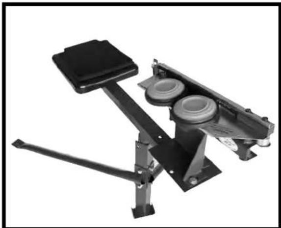
natural_image
Mechanical device with lever and mounting base (no visible text or symbols)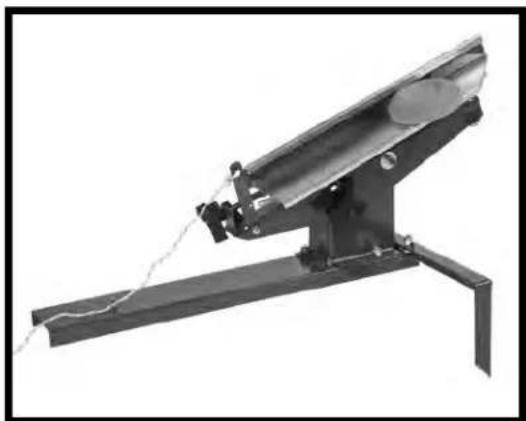
natural_image
Mechanical device with attached rod and chain, no visible text or symbolsTrius Trap Master Page 9
92S Trius Trap Page 7
Congratulations
You have just purchased a unique design and easy to use target trap.
Please read all directions before assembling and using your new trap.
Trius® a subsidiary of Lyman Products Corp 475 Smith Street, Middletown, CT 06457
800-22-LYMAN or 860-632-2020 www.triustraps.com
TRIUS 1-STEP
ASSEMBLY INSTRUCTIONS:
Tools Needed: 2 adjustable wrenches or 9/16 socket/open end or box end wrenches.
Your Trius 1 Step is preassembled as much as possible before shipping. The trap has been tested with the main spring that has been sent with it. By following the instructions, the trap should go together quickly and easily. Do not tighten nuts and bolts before all are in place. When tightening the lock nuts, remember lock nuts seem tight before really snug.
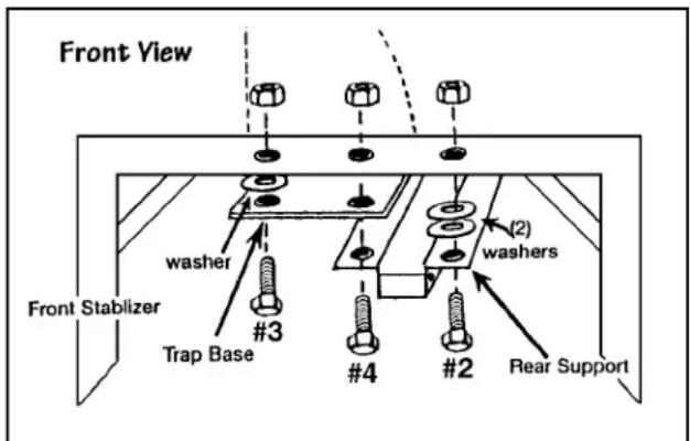
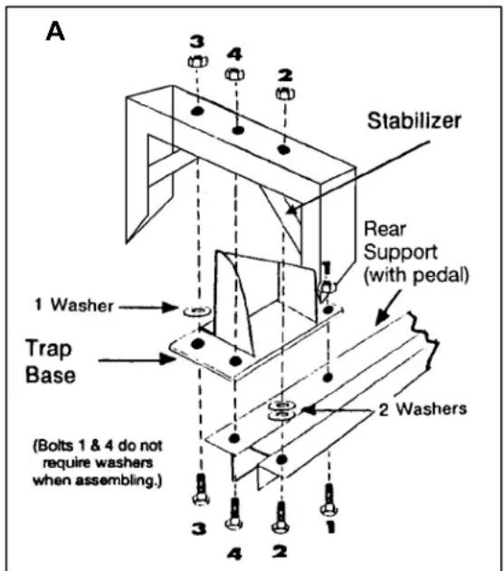
Put rear support with pedal, trap base and stabilizer together as shown in Illus. A. Please note that trap base goes in between the rear support and stabilizer.
Put bolt #1 from bottom through rear support and trap base as shown. Tighten nut finger tight.
Put bolt #2 from bottom through rear support, add 2 washers, then through the stabilizer. Tighten nut finger tight.
Put bolt #3 from bottom through trap base, add 1 washer, then through stabilizer. Tighten nut finger tight.
Put bolt #4 from bottom through rear support, trap base and stabilizer. Tighten nut finger tight.
You are now ready to tighten all bolts and nuts. Now place arm assembly onto trap base and secure with lock nut and elevation knob.
ATTACHING MAIN SPRING:
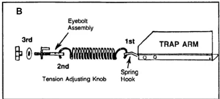
(Illus. B.) Raise pedal, extend arm forward, attach main spring to spring hook, then onto eyebolt assembly. Put eyebolt through rear bracket, add washer and adjusting knob. Important: Put spring through spring hook as shown. Do not push on pedal until chain is adjusted properly!
TENSION ADJUSTMENT:
Tighten tension knob just enough to have eyebolt take up full thread of knob. This should throw a fine target and be just right for teaching new shooters. For faster more difficult targets, increase tension by tightening knob. Doubles usually require higher tension. A regulation trap target flight is between 8 and 12 feet high at a point 10 yards from the trap, and the horizontal distance is between 48 and 52 yards.
Trius® Traps - 1 Step www.triustraps.com2
IMPORTANT
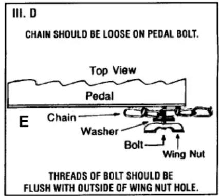
ADJUSTING HEIGHT AND RELEASE CHAIN:
Pedal should be at bottom of stroke when trigger releases arm.
TO ADJUST - Remove chain at pedal.
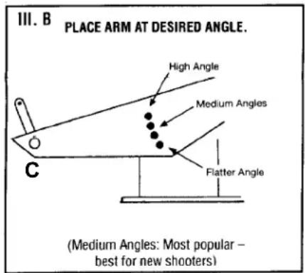
Secure frame at desired angle. (middle holes most popular). (Illus. C)
FLAT: bottom hole, difficult shot, short air time for targets
MEDIUM: middle holes, most popular, best for beginners
HIGH: top hole, most difficult shot
Arm should be extended in the release position.
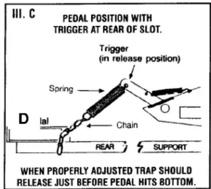
With pedal at bottom of stroke – resting between rear stabilizer, pull chain snug until release trigger is at rear of slot (Illus. D) with minimum tension on chain/spring. Place chain onto pedal bolt.
Tighten wing nut so threads of bolt are flush with wing nut hole. (Illus. E)
Chain should be loose on pedal bolt. When adjusted properly, pedal should release trigger at bottom of stroke.
IF NOT RELEASING TARGETS, SHORTEN CHAIN ON PEDAL BOLT.
IF RELEASING TARGETS TOO SOON, LENGTHEN CHAIN ON PEDAL BOLT. Safe operation of your trap is as important as safe gun handling. DO NOT STEP ON PEDAL UNTIL PATH OF ARM AND TARGET(S) ARE CLEAR.
OPERATION OF TRAP: Become familiar with trap before throwing targets and shooting. The trap's front legs should be pushed into the ground to help secure the trap for more consistent throws.
DIRECTIONAL ADJUSTMENT:
To change the direction that a traget will fly, change its position on the arm. For a left target, move the target fully up the arm against the high angle clip. If a center target is desired, move it down the arm slightly. For a right target, move it further down the arm.
IMPORTANT: Make sure path of throwing arm and targets is clear before operating trap.
1) Always stand to rear of trap.
2) Swing arm clockwise to cock trap.
3) Place target(s) on arm under clip. Clip pressure should be as little as necessary to hold targets.
4) Note: If target(s) slide off arm before release - step off pedal, increase clip tension and replace target(s).
5) Use either left or right foot on pedal BUT make sure the foot on the pedal is the forward foot. The foot NOT on the pedal should be the back foot. When shooting alone right-handed shooters release trap with left foot and left-handed shooters use right foot to release trap.

6) Step down on pedal with steady motion - DO NOT STOMP DOWN as this could cause targets to shift and break before thrown.
IMPORTANT – PLACE TARGET(S) ON ARM BEFORE STEPPING ON PEDAL. NOTE: The targets must be placed against the rubber rub strip, otherwise they may break. At the highest tension, targets may break when thrown. If this happens, reduce the tension.
OIL the bronze bushings and threads OCCASIONALLY. Oil the trap when you oil your guns. NOTE – PLACE TARGET(S) ON ARM BEFORE PUTTING FOOT ON PEDAL. Safe operation of your trap is as important as safe gun handling. DO NOT STEP ON PEDAL UNTIL PATH OF ARM AND TARGET(S) IS CLEAR
SAFETY:
The carrier arm and the thrown target can inflict serious injury. DO NOT walk in front of the trap. Place branches, stakes or other objects around the trap to prevent anyone from getting into the path of the carrier arm. No trap should be left where it can be cocked by strangers or trespassers. WARNING: Remove main spring when not in use. Do not operate trap without small trigger spring.
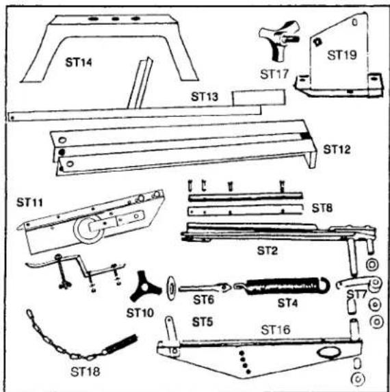
TRIUS 1 STEP CLAY TARGET TRAP PARTS LIST
To expedite delivery of parts we suggest you order them directly from TRIUS PRODUCTS. When ordering give Model Number, Part Number and Part Name. Parts not shown on this parts list may be purchased locally. Please call or visit our website for ordering and pricing information.
Part Key Part No. No. Name
10414T ST19 Base (T)
10404T ST2 Arm Assy. (incl. Key Nos. ST7 & ST8) (T)
10313 ST4 Main Spring
10546 ST5 Trigger Spring
10730T ST6 Eyebolt Assy. (includes adj. knob) (T)
10733T ST7 Spring Hook (w/ bushing and washers) (T)
10741T ST8 Rub Strip (complete with screws) (T)
10658 ST10 Tension Adjusting Knob
10734T ST11 High Angle Clip (T)
10738T ST12 Rear Support (pivot bolt included) (T)
10739T ST13 Pedal Unit only (pivot bolt included) (T)
10402T ST14 Front Stabilizer (T)
10419T ST16 Frame Assembly (T)
10679 ST17 Elevation Knob (with stud 5/16" thread)
10740T ST18 Release Chain with Spring (T)
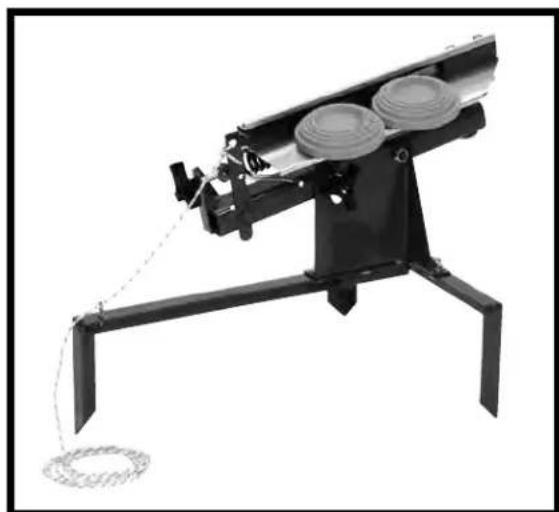
TRIUS BIRDSHOOTER
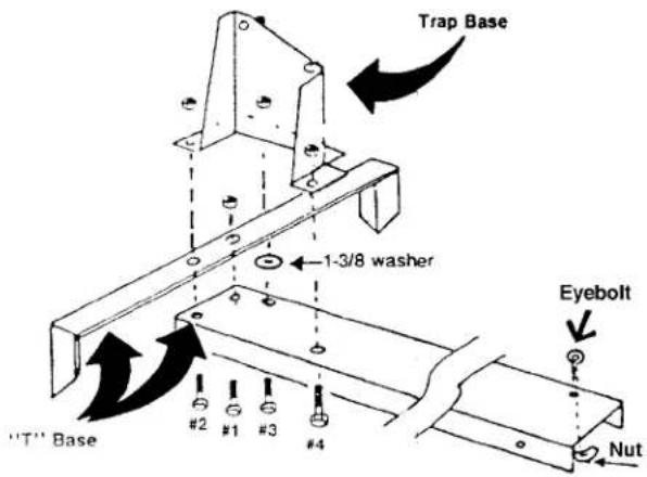
ASSEMBLING TRAP: tools needed – 2 adjustable wrenches or 9/16" sockets/open end or box wrenches. All hardware is supplied to assemble the trap
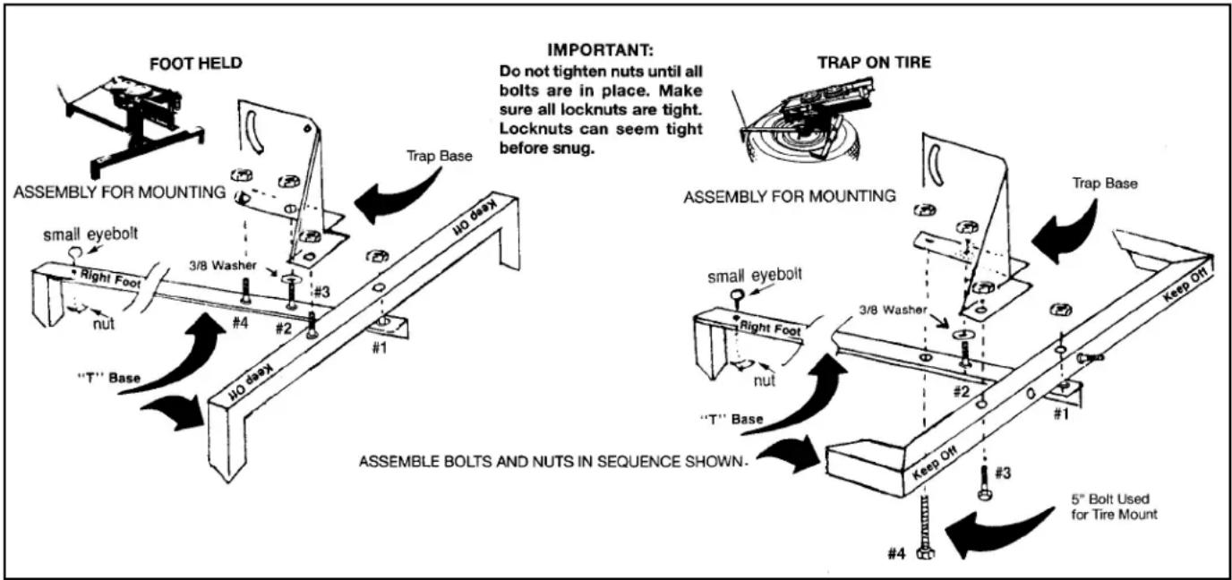
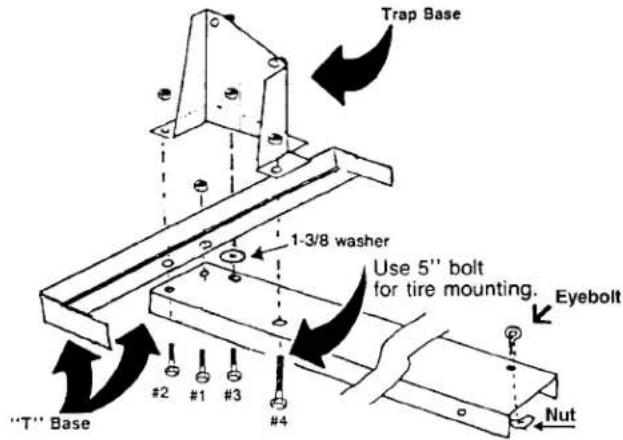
Please refer to the drawing below for the proper parts placement and sequence for tightening the nuts. Assemble the legs in a "T" shape first as shown. Then attach the trap to the legs as shown. If the trap is to be mounted on a tire, the front leg is turned so the feet run parallel to the ground. A spare nut and bolt are supplied for the one mounting hole which does not have the welded bolt in place.
IMPORTANT: Make sure all locknuts are tight. Locknuts can seem tight before they actually are.
Install the small eyebolt through the rear leg and secure it with the supplied nut.
Attach the throwing arm to the trap base with a supplied nut and washer, and then attach the angle adjustment knob with lock washer. Tie the pull cord to the throwing arm release trigger and pull it through the small eyebolt.
flowchart
graph TD
    A["FOOT HELD"] --> B["ASSEMBLY FOR MOUNTING"]
    B --> C["ASSEMBLY BOLTS AND NUTS IN SEQUENCE SHOWN."]
    C --> D["NO deep"]
    D --> E["trap Base"]
    E --> F["3/8 Washer"]
    F --> G["small eyebolt"]
    G --> H["nut"]
    H --> I[""T" Base"]
    I --> J["#1"]
    J --> K["NO deep"]
    K --> L["#2"]
    L --> M["#3"]
    M --> N["#4"]
    N --> O["NO deep"]
    O --> P["trap Base"]
    P --> Q["3/8 Washer"]
    Q --> R["#2"]
    R --> S["#1"]
    S --> T["Keep Off"]
    T --> U["#3"]
    U --> V["5" Bolt Used for Tire Mount"]
    V --> W["trap Base"]
    W --> X["3/8 Washer"]
    X --> Y["#2"]
    Y --> Z["#1"]
    Z --> AA["Keep Off"]
    AA --> AB["#4"]
MAIN SPRING & EYEBOLT ASSEMBLY: Place spring on spring hook first. (Arm should be in the extended uncocked position.) Place eyebolt on spring, then through rear bracket and add wing nut as shown in the exploded view below. (Be sure it is free to move at each end.) Make sure eyebolt threads are through the wing nut.
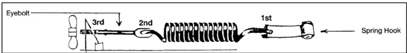
TENSION ADJUSTMENT: Tighten the wing nut only enough to remove any looseness or rattle in the spring linkage. This tension throws a fine target that has ample flight and yet is easy on the operator and easier to hit.
Become familiar with the trap and flight of the targets before trying a higher tension. Doubles require a higher tension.
Trius® Traps – Birdshooter www.triustraps.com5
SAFETY: The carrier arm and the thrown targets can inflict serious injury. DO NOT walk in front of the trap. Place branches, stakes or other objects around the trap to prevent anyone from getting into the path of the carrier arm. The cocked trap should NOT be left unattended. No trap should be left where it can be cocked by strangers or trespassers.
WARNING: Remove main spring when not in use.
NOTICE: The TRIUS 1-Step, TRIUS TRAP, BIRDSHOOTER, and TRAPMASTER are designed for many years of casual shooting enjoyment. These models ARE NOT designed for extensive or commercial use by Gun Clubs. SUCH USE VOIDS THE GUARANTEE.
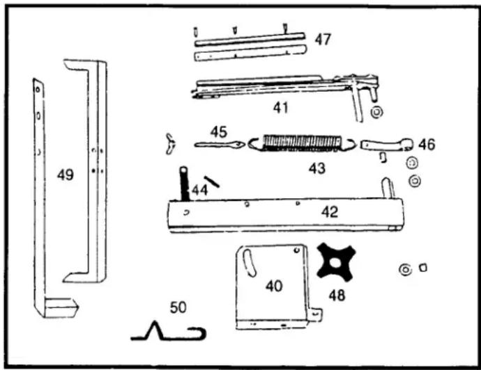
TRIUS MECHANICAL CLAY TARGET TRAP MODEL BIRDSHOOTER 2 PARTS LIST
Parts not shown on this parts list may be purchased locally. Parts listed should be ordered from Trius Products. Prices subject to change. Additional charge for shipping and handling. Please call or visit our website for ordering and pricing information.
Part Key
No. No. Name
Part
| 10455T | 40 | Base (T) |
| 10458T 41 | Arm Assembly (T) includes Key Nos. 46 & 47 | |
| 10470T 42 | Frame Assembly (T) | |
| 10313 | 43 | Main Spring |
| 10546 | 44 | Small Trigger Spring |
| 10731T 45 | Eyebolt Assembly (T) | |
| 10733T 46 | Spring Hook (with bushing and washers) (T) | |
| 10742T 47 | Rub Strip (complete with screws) (T) | |
| 10658 | 48 | Adjusting Knob |
| 10736T 49 | “T” Base (nuts & bolts included) (T) | |
| 10735T 50 | High Angle Retainer (T) (wire retainer, including foil tape) | |
THE ORIGINAL TRIUS TRAP TARGET TRAP MODEL "92S"
ASSEMBLING TRAP: Tools needed - 2 adjustable wrenches or 9/16" sockets/open end or box end.
IMPORTANT: Do not tighten nuts until all bolts are in place. Make sure all locknuts are tight. Locknuts can seem tight before snug. The bolts and nuts needed for mounting are furnished with the trap. After determining the desired "T" base mounting (see below), use appropriate assembly illustration. Put small eyebolt with nut at end of right foot per illustration.
PLEASE NOTE: When mounting trap base to a permanent base, i.e. concrete – we recommend a cushion (old pieces of tire, machinery vibration materials, etc.) between trap base and permanent base. Tighten bolts enough to allow slight movement. Use locknuts so they will not loosen.
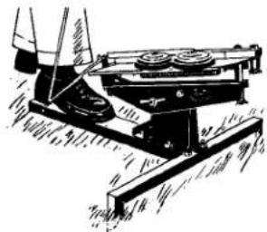
FOOT HELD
natural_image
Technical line drawing of a mechanical device with rotating components (no text or symbols)TRAP ON TIRE

natural_image
Technical line drawing of a mechanical assembly with a tire and mounted component (no text or symbols)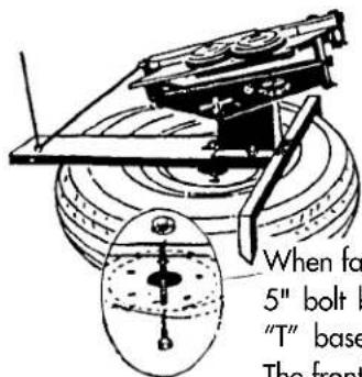
When fastening trap to tire with 5" bolt be careful not to bend "T" base when tightening nut. The front legs can also be rotated so that they are parallel to tire (see diagram below).
Assemble bolts and nuts in sequence shown.
FOOT HELD ASSEMBLY FOR MOUNTING
TRAP ON TIRE ASSEMBLY FOR MOUNTING
MAIN SPRING & EYEBOLT ASSEMBLY:
Place spring on spring hook first. (Arm should be in the extended uncocked position.) Place eyebolt on spring, then through rear bracket as shown in the exploded view below. Put washer on eyebolt and add knob. (Be sure it is free to move at each end.) Make sure eyebolt threads are through the knob.
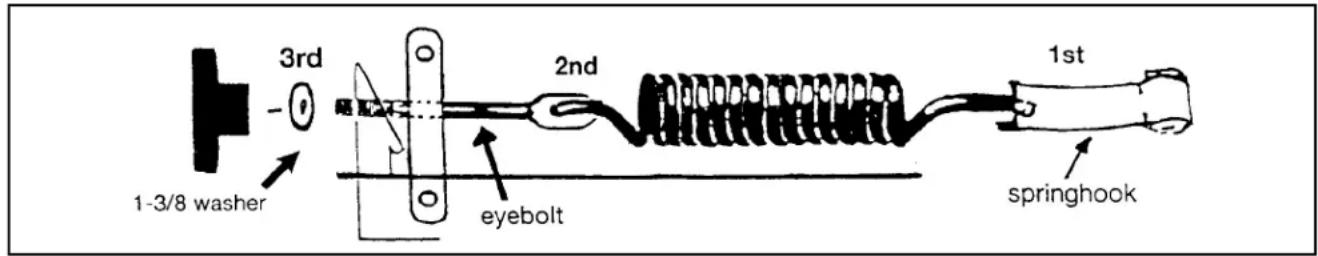
TENSION ADJUSTMENT: Tighten the knob only enough to remove any looseness or rattle in the spring linkage. This tension throws a fine target that has ample flight and yet is easy on the operator and easier to hit. Become familiar with the trap and flight of the targets before trying a higher tension. Doubles require a higher tension. Tightening the tension screw about 3/4 of an inch more is sufficient for doubles and fast singles.
SAFETY: The carrier arm and the thrown targets can inflict serious injury. DO NOT walk in front of the trap. Place branches, stakes or other objects around the trap to prevent anyone from getting into the path of the carrier arm. The cocked trap should NOT be left unattended. No trap should be left where it can be cocked by strangers or trespassers.
WARNING: Remove main spring when not in use. Shooters should be right of the trap; NEVER forward of the trap.
NOTICE: The TRIUS TRAP, TRIUS 1-STEP, BIRDSHOOTER, and TRAPMASTER are designed for many years of casual shooting enjoyment. These models are not designed for extensive or commercial use by Gun Clubs. SUCH USE VOIDS THE GUARANTEE.
TARGET TRAP MODEL "ORIGINAL TRIUS TRAP" "92S" PARTS LIST
To expedite delivery of parts we suggest you order them directly from TRIUS Products. When ordering, give Trap Model Number, Part No. and Part Name. Parts not shown on this parts list may be purchased locally. Prices subject to change. Please call or visit our website for ordering and pricing information.
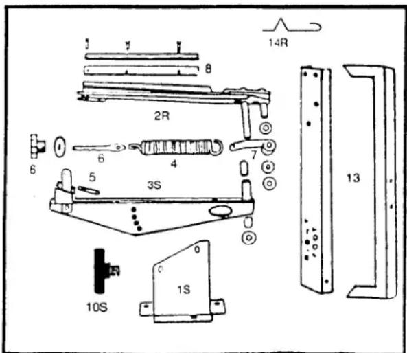
Part Key Part No. No. Name
| 10386T 1S Base (T) | ||
| 10328T | 2R Arm Assembly (T) includes Parts Nos. 7 & 8 | |
| 10622T | 3S Frame Assembly (T) | |
| 10313 | 4 | Main Spring |
| 10546 | 5 | Small Trigger Spring |
| 10730T | 6 | Eyebolt Assembly (T) |
| 10733T | 7 | Spring Hook (with bushing and washers) (T) |
| 10741T | 8 | Rub Strip (complete with screws) (T) |
| 10679 | 10S | Adjusting Knob w/stud (5/16") |
| 10737T | 13 | Steel "T" Base (nuts and bolts included) (T) |
| 10735T | 14R | High Angle Retainer (T)(wire retainer, including foil tape) |
TRIUS TRAPMASTER 2 MODEL
Your Trius TrapMaster 2 is quality constructed of heavy duty material and with reasonable care will give you many years of shooting enjoyment with a minimum of maintenance. The operator should familiarize himself with the trap and its operation before using it.
TRAPMASTER ASSEMBLY: Tools Required: 2 - 9/16" wrenches or 2 adjustable crescent wrenches, plus 1 screwdriver.
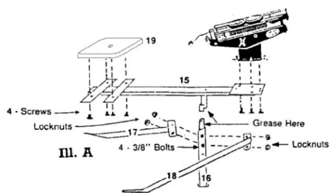
1) Using 4 lock nuts and bolts, fasten the tubular legs (17 & 18) to the center support post (16) as in Illustration (A). Put nuts on outside of leg brackets. Use 2 - 9/16 wrenches or 2 adjustable crescent wrenches.
IMPORTANT: Do not tighten nuts until all bolts are in place. Make sure all locknuts are tight. Locknuts can seem tight before snug.
2) Fasten the operator's seat (19) to the pivoting channel frame (15). Place channel (15) onto the center support post (16). A small amount of grease has been applied to the pivot pin when packaged. Important: Keep this pivot pin well greased or oiled.
3) Assemble the trap throwing arm assembly and base (see Birdshooter 2 instructions.) Use the three supplied bolts and nuts to fasten trap assembly to the pivoting channel frame (15). Referring to Illustration C match the trap with correct holes.
III. C
Birdshooter
92S Trius Trap
III. B
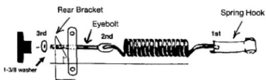
MAIN SPRING & EYEBOLT ASSEMBLY: Assemble the spring and eyebolt as shown in Illustration B. Arm should be in the extended uncocked position. Place spring on spring hook and then onto eyebolt. Place through rear bracket, add washer and put on tension knob as shown in Illustration B. Be sure spring is free to move at each end.
TENSION ADJUSTMENT: Tighten the knob only enough to remove any looseness or rattle in the spring linkage. This tension throws a fine target that has ample flight and yet is easy on the operator and easier to hit.
Become familiar with the trap and flight of the targets before trying a higher tension. Doubles require a higher tension. Tightening the tension screw about 3/4 of an inch more is sufficient for doubles and fast singles.
SAFETY: Safety must be practiced at all times when using the TrapMaster 2 as you would anytime you are using a gun. The carrier arm and thrown target can inflict serious injury. Do not walk in front of the trap. Place branches, stakes, or other objects around the trap to prevent anyone from getting into the path of the carrier arm or target. Forethought must be given to protection for the operator from those shooting. The operator himself must keep his hands and legs clear of the carrier arms path. Keep feet off the tubular legs. Never leave the trap arm in a cocked position when sitting down or getting off the operator's seat. Always remove spring when finished shooting and/or transporting trap.
NOTICE: The TRIUS 1-Step, TRIUS TRAP, BIRDSHOOTER 2, and TRAPMASTER 2 are designed for many years of casual shooting enjoyment. These models ARE NOT designed for extensive or commercial use by Gun Clubs.
TARGET TRAP TRAPMASTER 2
PARTS LIST
Parts not shown on this parts list may be purchased locally. Please call or visit our website for ordering and pricing information.
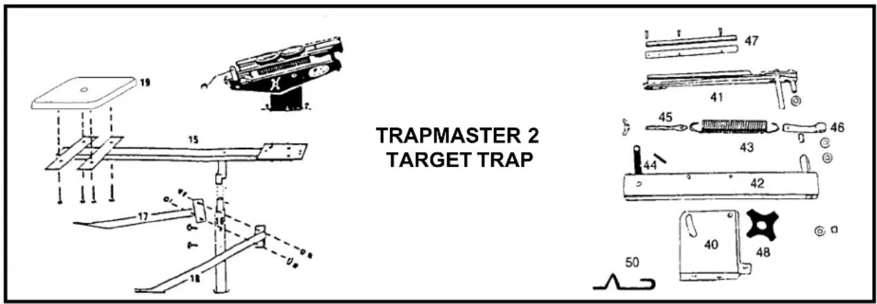
Part No. Key No. Part Name
| 10455T | 40 | Base (T) |
| 10458T 41 | Arm Assembly includes Key Nos. 46 & 47 (T) | |
| 10470T 42 | Frame Assembly (T) | |
| 10313 | 43 | Main Spring |
| 10546 | 44 | Small Trigger Spring |
| 10731T 45 | Eyebolt Assembly (T) | |
| 10733T 46 | Spring Hook (with bushing and washers) (T) | |
| 10742T 47 | Rub Strip (complete with screws) (T) | |
| 10658 | 48 | Adjusting Knob |
| 10735T 50 | High Angle Retainer (T) (wire retainer, including foil tape) | |
| 10330T 15 | Pivoting Channel Frame (T) | |
| 10329T 16 | Center Support Post (T) | |
| 10337T 17 | Left Leg (T) | |
| 10336T 18 | Right Leg (T) | |
| 10501T 19 | Seat Assembly (hardware included) (T) | |
DIRECTIONS AND SUGGESTIONS FOR ALL TRIUS TARGET TRAPS
SAFETY: The carrier arm and the thrown targets can inflict serious injury. DO NOT walk in front of the trap. Place branches, stakes or other objects around the trap to prevent anyone from getting into the path of the carrier arm.
The cocked trap should NOT be left unattended. No trap should be left where it can be cocked by strangers or trespassers.
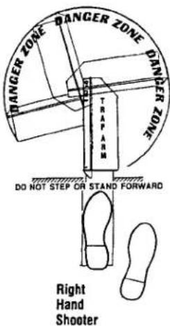
WARNING: Remove main spring when not in use. Shooters should be right of the trap; NEVER forward of the trap.
OPERATION OF THE TRAP: When using a foot held trap stand to the REAR and LEFT SIDE of the trap to cock it. MAKE SURE RIGHT FOOT IS ON PIECE MARKED "RIGHT FOOT" WHEN COCKING. Cock by grasping the rear raised portion of the carrier arm (marked PULL HERE) with one or both hands. DO NOT PULL ON THE THIN FORWARD EDGE OF THE ARM. NOTE: The target must be placed against the rubber rub strip, otherwise it may break.
OIL the bronze bushings and threads OCCASIONALLY. Oil the trap when you oil your guns.
TENSION ADJUSTMENT: Tighten the knob or wing nuts only enough to remove any looseness or rattle in the spring linkage. This tension throws a fine target that has ample flight and yet is easy on the operator and easier to hit. Make sure eyebolt threads are through the knob or wing nuts. Become familiar with the trap and flight of the targets before trying a higher tension. Doubles require a higher tension. Tightening the tension about 3/4 of an inch more is sufficient for doubles and fast singles. See below for adjustments needed for throwing Mini (60mm) and Midi (90mm).
ADJUSTING DIRECTION OF FLIGHT: A regulation trap target flight is between 8 and 12 feet high at a point 10 yards from the trap, and the horizontal distance is between 48 and 52 yards. A target placed near the middle of the carrier arm will throw a straight-away target. Use the straight-away target to judge flight and to adjust the angle of the trap. If you desire to throw targets at a greater angle than regulation, the targets may have a tendency to slide down the arm. If this occurs, we suggest you use the High Angle Retainer.
Placing the target at various positions on the arm will vary the horizontal angle of flight. If the target is placed too far from the center of the arm, good results will not be obtained. However, some shooters may desire erratic targets to simulate hunting conditions.
At the highest tension, targets placed near the pivot pin may break when thrown. If that happens move the target toward the middle of the arm or reduce the tension.
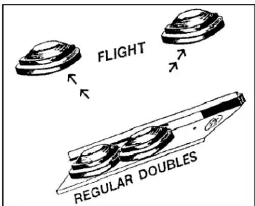
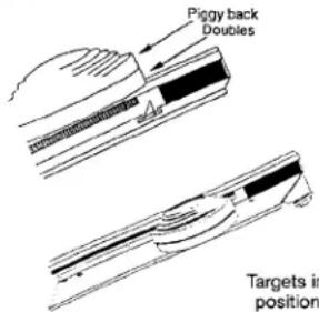
REGULATION TYPE DOUBLES place one target against rub strip near the block and pivot pin and the other target below it.
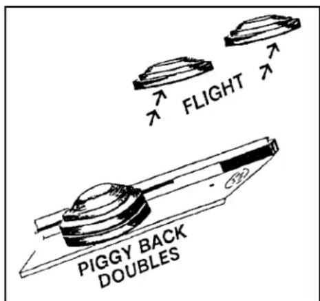
PIGGY BACK DOUBLES, place targets on top of each other and then put both targets on arm.
If piggy back doubles break - either reduce the amount of spring tension, move the targets away from the pivot pin, or both.
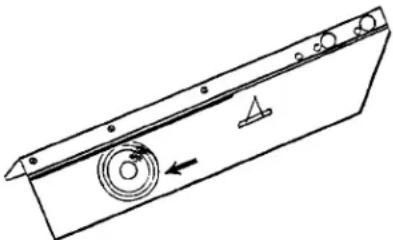
HIGH ANGLE RETAINER
Only needed when throwing abnormally high targets that slide down the arm. Cock arm and gently place target over retainer, resting inside edge of target against retainer. Piggy back doubles – put one target on top of the other and gently place both targets over retainer. Place targets against rub strip before throwing.
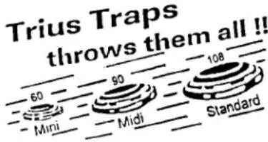
THROWING MINI (60 mm) and/or MIDI (90 mm) TARGETS
These targets, used in sporting clays/hunter's clays, may require several adjustments because of the distance a TRIUS trap will throw standard targets at almost minimum tension. You will need to possibly make 2 adjustments to throw the smaller targets.
1) Place the targets toward the end of arm away from pins and block.
2) You may have to reduce spring tension – but make sure the eyebolt is at least through the knob or wing nuts.
Side view of High Angle Retainer
natural_image
Technical line drawing of a mechanical component with circular features and an arrow indicating direction (no text or symbols)HUNTER'S CLAYS
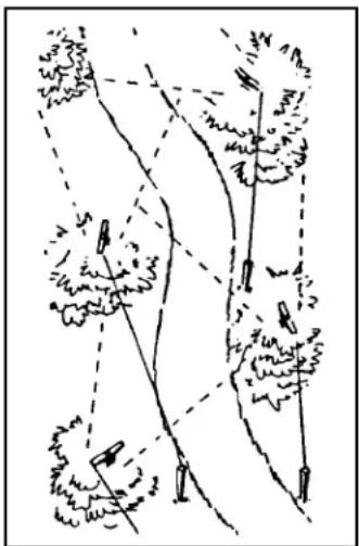
Where clay targets fly like game birds. The idea of Hunter's Clays is to simulate shots you'll encounter when hunting for your favorite game. Two traps are enough for a good layout. Three or four traps will make your layout better. This game is designed to take advantage of the natural terrain in your area.
You position the traps where you want. To improve your duck, dove or goose shooting skills, throw high targets from a hill or barn. If you hunt for grouse or woodcock, place the traps in appropriate cover. For rabbits, throw target close to the ground. You also decide whether you want each trap to throw single or double targets.
Get together with friends and set up a Hunter's Clays layout. Good Shooting! Above the traps are located along a path and concealed by natural cover so the direction of flight is not known. The Trius Trap is particularly well suited for this use since doubles as well as singles can be thrown from the same trap. A walk of 4 traps gives a shooter 5 shots down the walk - 3 singles and a double. Changing the trap on which the double is thrown can add variety. Use the low tension for slow flight, since the target leaves the trap much faster than a flushing bird. For this reason, this type of shooting requires faster gun handling than hunting. Until the shooter is skilled, it is advisable for the operator to say "bird", "target" or "pull" an instant before tripping the trap so the shooter can be alerted. Handicap the
natural_image
Diagram showing multiple trees with dashed and solid lines indicating paths or relationships (no text or symbols)
better shooter by having him shoot from a greater distance from the trap. Keep the games simple so good scores can be made. "The pleasure is in the hitting." Allow the novice to stand closer to the trap until he learns to hit regularly. "The shooter learns only by hitting."
NOTICE: The TRIUS TRAP, TRIUS 1-STEP, BIRDSHOOTER, and TRAPMASTER are designed for many years of casual shooting enjoyment. These models are not designed for extensive or commercial use by Gun Clubs. SUCH USE VOIDS THE GUARANTEE.
Trius® a subsidiary of Lyman Products Corp
475 Smith Street Middletown, CT 06457
800-22-LYMAN or 860-632-2020 www.triustraps.com