T600HPP-3 - Thermostat Johnson Control - Free user manual and instructions
Find the device manual for free T600HPP-3 Johnson Control in PDF.

User questions about T600HPP-3 Johnson Control
0 question about this device. Answer the ones you know or ask your own.
Ask a new question about this device
Download the instructions for your Thermostat in PDF format for free! Find your manual T600HPP-3 - Johnson Control and take your electronic device back in hand. On this page are published all the documents necessary for the use of your device. T600HPP-3 by Johnson Control.
USER MANUAL T600HPP-3 Johnson Control
T600HPx-3 Heat Pump Thermostats
Installation Instructions
T600HPN-3, T600HPP-3
Part No. 24-9890-595, Rev. —
Issued September 20, 2006
Applications
The T600HPN-3 non-programmable and T600HPP-3 programmable thermostats are specifically designed for control of heat pump commercial heating and cooling equipment.
IMPORTANT: The T600HPx-3 Thermostat is intended to provide an input to equipment under normal operating conditions. Where failure or malfunction of the thermostat could lead to personal injury or property damage to the controlled equipment or other property, additional precautions must be designed into the control system. Incorporate and maintain other devices such as supervisory or alarm systems or safety or limit controls intended to warn of or protect against failure or malfunction of the thermostat.
North American Emissions Compliance
United States
This equipment has been tested and found to comply with the limits for a Class A digital device pursuant to Part 15 of the FCC Rules. These limits are designed to provide reasonable protection against harmful interference when this equipment is operated in a commercial environment. This equipment generates, uses, and can radiate radio frequency energy and, if not installed and used in accordance with the instruction manual, may cause harmful interference to radio communications. Operation of this equipment in a residential area is likely to cause harmful interference, in which case the user will be required to correct the interference at his/her own expense.
Canada
This Class (A) digital apparatus meets all the requirements of the Canadian Interference-Causing Equipment Regulations.
Location Considerations
Locate the T600HPx-3 thermostat:
- on a partitioning wall, approximately 5 ft (1.5 m) above the floor in a location of average temperature
- away from direct sunlight, radiant heat, outside walls, behind doors, air discharge grills, stairwells, or outside doors
- away from steam or water pipes, warm air stacks, unconditioned areas (not heated or cooled), or sources of electrical interference
Note: Allow for vertical air circulation to the T600HPx-3 thermostat.
To install the thermostat:
- Use a Phillips-head screwdriver to remove the security screw on the bottom of the thermostat cover.
- Pull the bottom edge of the thermostat cover and open the thermostat as illustrated in Figure 1.
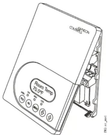
Figure 1: Removing the Thermostat Cover
- Carefully pull the locking tabs on the right side of the thermostat mounting base and unlock the Printed Circuit Board (PCB). Open the PCB to the left as illustrated in Figure 2.
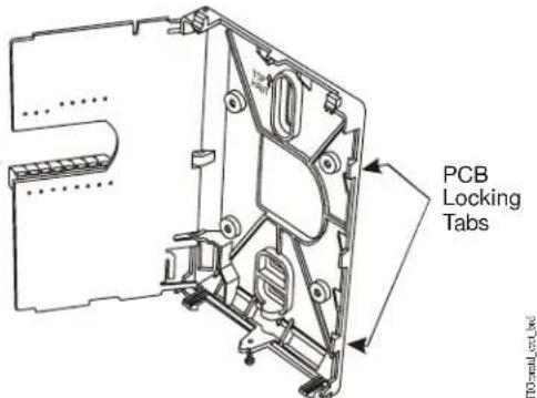
Figure 2: Opening the Thermostat PCB
- Pull approximately 6 in. (152 mm) of wire from the wall and insert the wire through the hole in the thermostat mounting base.
- Align the thermostat mounting base on the wall and use the base as a template to mark the two mounting hole locations.
Note: Be sure to position the thermostat mounting base so that the arrow on the base points upward to indicate the top of the thermostat.
- Drill a 3/16 in. (5 mm) hole at each of the two marked locations and tap nylon anchors (included with the thermostat) flush to the wall surface.
- Position the thermostat mounting base on the wall and use the two mounting screws (included with the thermostat) to secure the base to the surface as illustrated in Figure 3.
Note: Be careful not to overtighten the mounting screws.
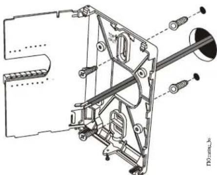
natural_image
Technical line drawing of a mechanical assembly with no visible text or symbolsFigure 3: Securing the Thermostat Mounting Base to the Wall
- Swing the PCB back to the right and carefully snap it into the locking tabs on the thermostat mounting base.
- Pull the pull-tabs on each of the connectors and remove the screw terminal blocks as illustrated in Figure 4.
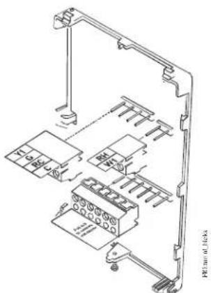
Figure 4: Removing the Screw Terminal Blocks
Wiring
When an existing thermostat is replaced, remove and label the wires to identify the terminal functions. When a T600HPx-3 thermostat is replaced, simply remove the old screw terminal blocks and reinsert them onto the PCB of the replacement thermostat.

CAUTION: Risk of Electric Shock.
Disconnect the power supply before making electrical connections to avoid electric shock.

CAUTION: Risk of Property Damage.
Do not apply power to the system before checking all wiring connections. Short circuited or improperly connected wires may result in permanent damage to the equipment.
IMPORTANT: Make all wiring connections in accordance with local, national, and regional regulations. Do not exceed the electrical ratings of the T600HPx-3 thermostat.
To wire the thermostat:
- Strip the ends of each wire a 1/4 in. (6 mm) and connect them to the appropriate screw terminals as indicated in Figure 5.
- Carefully push any excess wire back into the wall. Seal the hole in the wall with fireproof material to prevent drafts from affecting the ambient temperature readings.
- Reinsert the screw terminal blocks onto the PCB.
- Reattach the thermostat cover to the mounting base (top side first).
Note: Use a Phillips-head screwdriver to reinstall the security screw on the bottom of the thermostat cover.
FIGT800HPX3 mbLK
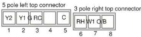
Figure 5: Terminal Blocks
Table 1: Terminal Identification (See Figure 5.)
| Number | Label | Function |
| 1 | Y2 | Energizes second-stage compressor on a call for heating or cooling. |
| 2 | Y1 | Energizes first-stage compressor on a call for heating or cooling. |
| 3 | G | Energizes fan in accordance with selected fan mode. |
| 4 | RC | 24 VAC from equipment transformer |
| 5 | C | 24 VAC (Common) from equipment transformer |
| 6 | RH | 24 VAC for auxiliary heating. |
| 7 | W1 | Energizes on a call for auxiliary heating. |
| 8 | O/B | Reversing valve. Configurable to energize a valve on a call for heating or a call for cooling. |
| 10 | Aux | Auxiliary output |
| 11 | DI1 | Configurable Digital Input 1 |
| 12 | DI2 | Configurable Digital Input 2 |
| 13 | RS | Remote Room Temperature Sensor |
| 14 | Scom | Sensor Common |
| 15 | OS | Outdoor Air Sensor |
| 16 | MS | Not Used |
flowchart
graph TD
A["Comp 1"] --> B["Comp 2"]
B --> C["24 VAC Thermostat Power"]
D["Y2 Y1"] --> E["G"]
E --> F["RC"]
F --> G["C"]
H["RH"] --> I["W1"]
I --> J["Rev Valve"]
K["AUX"] --> L["D1"]
L --> M["D2"]
N["Aux"] --> O["Remote Room Sensor"]
P["Isolated Contact - Lighting - On/Off Actuation - Exhaust Fan"] --> Q["Exhaust Fan"]
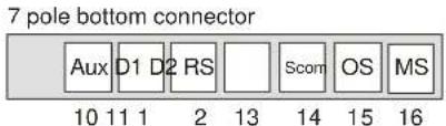
R["If using the same power source for the thermostat and heating loads, install a jumper across RC and RH."] --> S["Reactor with transformer"]
Figure 6: Wiring the T600HPx-3 Thermostats
flowchart
graph TD
    A["Separate 24 VAC Transformer"] --> B["R3"]
    A --> C["R2"]
    A --> D["R1"]
    A --> E["G"]
    A --> F["RC"]
    A --> G["C"]
    A --> H["RH"]
    A --> I["W1"]
    A --> J["O/B"]
    A --> K["R4"]
    B --> L["To Auxiliary Heat Circuit"]
    C --> L
    D --> L
    E --> L
    F --> L
    G --> L
    H --> L
    I --> L
    J --> L
    K --> L
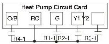
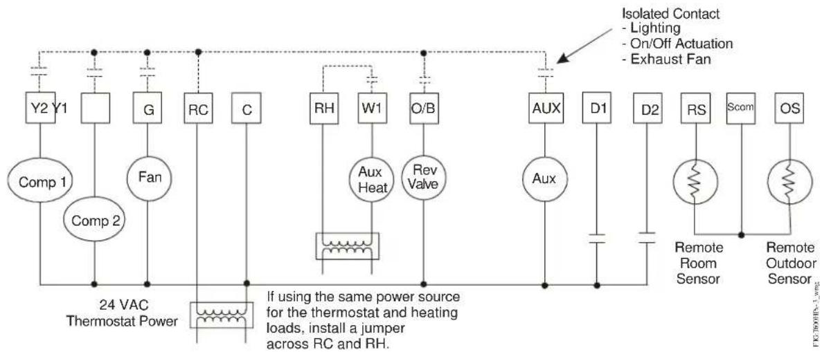
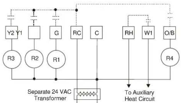
Note: Use 24 VAC interface relays (provided by the user).
ITG 1500HPX3_IVDC
Figure 7: Wiring the T600HPx-3 Thermostat for VDC Applications
Setup and Adjustments
Thermostat Operation Overview
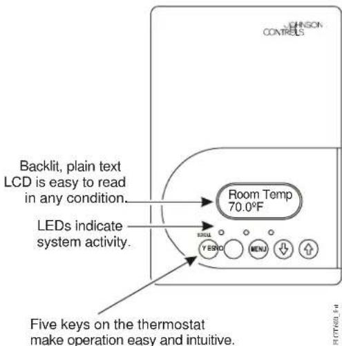
Figure 8: Front Cover of Thermostat
Thermostat User Interface Keys
The T600HPx-3 thermostat user interface consists of five keys on the front cover (as illustrated in Figure 8). The function of each key is as follows:
• U set the YES/SCROLL key to:
- confirm menu selections and to advance to the next menu item
- stop the Status Display Menu from scrolling and to manually scroll to the next parameter on the menu
Note: When the thermostat is left unattended for 45 seconds, the thermostat display resumes scrolling.
-
Use the NO key to decline a parameter change a to advance to the next menu item.
• U set the MENU key to: -
access the Main User Menu or exit the menu
- access the Installer Configuration Menu or to exit the menu (See the Configuring the T600HPx-3 Thermostat section.)
- Use the UP/DOWN arrow keys to change the configuration parameters and to activate a setpoint adjustment.
Backlit Liquid Crystal Display (LCD)
The T600HPx-3 thermostat includes a 2-line, 8-character backlit display. Low-level backlighting is present during normal operation, and it brightens when any user interface key is pressed. The backlight returns to low level when the thermostat is left unattended for 45 seconds.
Light-Emitting Diodes (LEDs)
Three LEDs are included to indicate the fan status, call for heat, or call for cooling:
• T h e FAN LED is on when the fan is on.
- The AUX HEAT LED is on when auxiliary heat is on
- The HEAT-PUMP LED is on when the heat-pump compressor is on.
Programming Overview
There are three menus used to view, program, and configure the T600HPx-3 thermostat:
The Status Display Menu is displayed during normal thermostat operation. This menu continuously scrolls through the following parameters:
- Room Temperature
• Day and Time (T600HPP-3) - System Mode
- Occupancy Status – Occupied/Unoccupied/Override
- Outdoor Temperature – An outdoor air temperature sensor must be connected.
- Applicable Alarms – The backlight lights up as an alarm condition is displayed.
Note: Press the YES/SCROLL key to temporarily stop this menu from scrolling.
The Main User Menu is used to access and change the basic operating parameters of the thermostat. Access this menu by pressing the MENU key during normal thermostat operation.
The Installer Configuration Menu is used to set up the thermostat for application-specific operation. To access this menu, press and hold the MENU key for approximately 8 seconds.
Configuring the T600HPx-3 Thermostat
The T600HPx-3 thermostat comes from the factory with default settings for all configurable parameters. The default settings are shown in Table 2. To reconfigure the parameters via the thermostat, follow the steps in this section.
- To access the Installer Configuration Menu, press and hold the MENU key for approximately 8 seconds.
- Once the Installer Configuration Menu begins, press the NO key to scroll through the parameters listed in Table 2.
- When the desired parameter is displayed, use the YES key to choose the desired selection option.
- Press the YES key and then the NO key to continue scrolling through the parameters.
To exit the Installer Configuration Menu any time, press the MENU key, and at the exit prompt, press the YES key. To pass over a parameter without changing it, press the NO key.
When the thermostat is in the Installer Configuration Menu and left unattended for approximately 8 seconds, the thermostat reverts to the Status Display Menu.
Configuring Inputs DI1 and DI2
When DI1 and DI2 are configured for an alarm condition, an alarm condition is displayed locally when the input is closed. An alarm message is included on the scrolling Status Display Menu and when the message is displayed, the backlight momentarily lights up.
Each input can be configured to the Selection Options included in Table 2.
Table 2: Installer Configuration Menu (Part 1 of 5)
| Parameter Appearing on Display | Description and Default Selection Options | |
| DI1 ^1 | Configuration of Digital Input 1. Default: None | (None): No function is associated with an input.(Service): A Service alarm is displayed on the thermostat when the input is energized. This input can be tied into the air conditioning unit control card, which provides an alarm should there be a malfunction.(Filter): A Filter alarm is displayed. This alarm can be connected to a differential pressure switch that monitors a filter.(RemOVR): Temporary occupancy request via a remote input. This override function is controlled by a manual remote occupancy override. When enabled, this condition disables the override capability of the thermostat.(RemNSB): Remote Night Setback (NSB) via a time clock input, an occupancy sensor, or from a voltage-free contact.Contact open = Occupied; contact closed = Unoccupied. |
Table 2: Installer Configuration Menu (Part 2 of 5)
| Parameter Appearing on Display | Description and Default | Selection Options | |||
| DI2^1 | Configuration of Digital Input 2. Default: None | (None): No function is associated with an input.(Service): A Service alarm is displayed on the thermostat when the input is energized. This input can be tied into the air conditioning unit control card, which provides an alarm should there be a malfunction.(Filter): A Filter alarm is displayed. This alarm can be connected to a differential pressure switch that monitors a filter.(RemOVR): Temporary occupancy request via a remote input. This override function is controlled by a manual remote occupancy override. When enabled, this condition disables the override capability of the thermostat.(RemNSB): Remote Night Setback (NSB) via a time clock input, an occupancy sensor, or from a voltage-free contact.Contact open = Occupied; contact closed = Unoccupied. | |||
| Lockout Selectable Lockout Levels for limiting end-user keypad interaction. Default: 0 | Function Lockout Level | ||||
| (0) (1) (2) | |||||
| Occupancy Override Access Access No Access | |||||
| Permanent Temperature Setpoints | Access No Access No Access | ||||
| Temporary Temperature Setpoints | Access Access No Access | ||||
| System Mode Setting Access No Access No Access | |||||
| Fan Mode Setting Access No Access No Access | |||||
| Schedule Setting^5 | Access No Access No Access | ||||
| Clock Setting^5 | Access Access Access | ||||
| Permanent Hold^5 | Access No Access No Access | ||||
| Pwr del^2 | Sets the delay time period at thermostat power up, or at each time power is removed and reapplied, before any operation (fan, heating, or cooling) is authorized. Also can be used to sequence the startup of multiple units in one location. Default: 10.0 sec | Range: 10.0 to 120.0 sec | |||
| Frost pr Provides a minimum heating setpoint of 42.0°F/5.5°C to prevent freezing in the zone controlled by the thermostat. Forces system to Emergency Mode. Default: off | (on): Enabled(off): Disabled | ||||
| Heat max^3 | Sets the Occupied and Unoccupied maximum Heating setpoint values. Default: 90.0°F/32.0°C | Range: 40.0°F/4.5°C to 90.0°F/32.0°C | |||
| Cool min^3 | Sets the Occupied and Unoccupied minimum Cooling setpoint values. Default: 54.0°F/12.0°C | Range: 54.0°F/12.0°C to 100.0°F/37.5°C | |||
Table 2: Installer Configuration Menu (Part 3 of 5)
| Parameter Appearing on Display | Description and Default Selection Options | |
| Anticycl Anti-Short Cycle timer sets the minimum on/off times for heating and cooling stages. Default: 2.0 min | Range: 0.0 to 5.0 min adjustable in 1-minute increments Set the anti-short cycle timer to 0.0 min for equipment that already has its own anti-short cycle timer. | |
| Heat cph Sets the maximum number of Heating cycles per hour. Default: 4.0 | Range: 3.0 to 8.0 cycles per hour | |
| Cool cph Sets the maximum number of Cooling cycles per hour. Default: 4.0 | Range: 3.0 or 4.0 cycles per hour | |
| Deadband Sets the minimum deadband between the heating and cooling setpoints. Default: 2.0F°/1.0C° | Range: 2.0F°/1.0C° to 4.0F°/2.0C° adjustable in 1.0F°/0.5C° increments | |
| Fan cont Determines how the fan is activated in response to Emergency Heat mode. Fan cont applies to W1 (auxiliary heat) and Fan Mode auto only. Fan cont does not affect fan operation on a call for cooling or heating to the compressor (Y1 and Y2). Default: on | (off): The thermostat will not activate the fan in response to a call for Emergency Heat. The fan is activated by the equipment fan and limit control.(on): Enables the thermostat to activate the fan in response to a call for heating or cooling. | |
| Fan del Fan delay extends fan operation after a heating or cooling cycle has ended. Default off | (on): Extends fan operation by 60 seconds after a heating or cooling cycle has ended.(off): No extension of fan operation after a heating or cooling cycle has ended. The fan delay is only active when the fan is in the Auto mode. | |
| TOccTime Sets the duration of the Temporary Occupancy Time (when the thermostat is in the Unoccupied mode) when a Schedule Override Function is enabled using either the Main User Menu or DI1 or DI2 configured as a temporary override remote contact (RemOVR). Sets the effective duration of the Temporary heating or cooling setpoints set using the up/down arrow keys. default: 3.0 hrs | Range: 0.0 to 12.0 hrs adjustable in 1-hour increments | |
| Cal RS Sets the desired room air temperature sensor calibration (offset). The offset can be added to or subtracted from the actual displayed room temperature. Default: 0.0F°/0.0C°C | Range: -5.0F°/-2.5C° to 5.0F°/2.5C° adjustable in 1.0F°/0.5C° increments | |
| Cal OS Sets the desired outdoor air temperature sensor calibration (offset). The offset can be added to or subtracted from the actual displayed room temperature. Default: 0.0F°/0.0C° | Range: -5.0F°/-2.5C° to 5.0F°/2.5C° adjustable in 1.0F°/0.5C° increments | |
Table 2: Installer Configuration Menu (Part 4 of 5)
| Parameter Appearing on Display | Description and Default Selection Options | |
| HP stage Sets the number of heat pump compressor stages. Default: 2.0 | (1.0): One Stage(2.0): Two StagesReverts the operation of a two-stage thermostat to a single-stage thermostat when the second cooling stage is not needed. | |
| H lock4 | Discontinues heating operation in response to the outdoor air temperature. Requires that an outdoor air temperature sensor be installed and connected. Default: 120°F/49°C | Range: -15°F/-26°C to 120°F/49°C adjustable in 5F°/5C° increments |
| C lock4 | Discontinues cooling operation in response to the outdoor air temperature. Requires that an outdoor air temperature sensor be installed and connected. Default: -40°F/-40°C | Range: -40°F/-40°C to 95°F/35°C adjustable in 5F°/5C° increments |
| 2/4event5 | Sets the number of events within a 24-hour period. Default: 2.0 | (2.0): Two events (one occupied and one unoccupied) within a 24-hour period(4.0): Four events (two occupied and two unoccupied) within a 24-hour period |
| Aux cont Energ | zes peripheral devices (lighting equipment, exhaust fans, and economizers). Default: n.o. | (n.c.): Contact open = Occupied; contact closed = Unoccupied(n.o.): Contact closed = Occupied; contact open = UnoccupiedThe contact toggles with the internal Occupied/Unoccupied schedule (or the NSB contact on one of the digital inputs, if used). |
| Prog rec5 | Provides the desired occupied temperature either at the start of the occupied schedule or after the occupied schedule begins.Note: Progressive recovery is disabled if either DI1 or DI2 is configured as remote NSB. Default: off | (on): Enabled (provides the desired occupied temperature at the start of the occupied schedule)(off): Disabled (provides the desired occupied temperature after the occupied schedule begins) |
| Hi b. p.4 | Sets the high balance point – the outdoor air temperature at which the auxiliary heat is not used. Default: 90.0°F/32.0°C | Range: 34.0°F/1.0°C to 90.0°F/32.0°CAbove the high balance point, only the heat pump is used to maintain the heating setpoint. If no outdoor air sensor is connected to Terminal OS, auxiliary heat pump operation may still be used above the high balance point. |
| Lo b. p.4 | Sets the low balance point – the outdoor air temperature at which the heat pump operation terminates when the heat pump is in the heating mode. Default: -12.0°F/-24.0°C | Range: -40.0°F/-40°C to 30.0°F/-1.0°CBelow the low balance point, only the auxiliary heat is used to maintain the heating setpoint. Heat pump operation may still be used below the low balance point if no outdoor air sensor is connected to Terminal OS. |
Table 2: Installer Configuration Menu (Part 5 of 5)
| Parameter Appearing on Display | Description and Default Selection Options | |
| Comf/eco Selects how the auxiliary heat is used.Default:comfort | (economy)– in the heating mode: If the heat pump is not able to satisfy the heating setpoint, the auxiliary heat is energized to satisfy the setpoint only when the temperature has dropped 2F^/1C^ below the heating setpoint.Note:Selecting economy in the heating mode adds a deadband between the heat pump and auxiliary heat. The actual temperature maintained is lower than the true heating setpoint to maximize the heat pump operation. When the outdoor air temperature drops below the low balance point, the deadband is eliminated.(economy)– in the emergency heat mode: The setpoint that is maintained is the heating setpoint.(comfort)– in the heating mode: If the heat pump is not able to satisfy the heating setpoint, the auxiliary heat is energized to satisfy the setpoint. | |
| Re valve Governs the reversing valve operation.Default:O | (B):Energizes the valve in heating operation (valve is normally cool)(O):Energizes the valve in cooling operation (valve is normally heat) | |
| Comp/aux Sets the mode of interaction between the heat pump and the auxiliary heat.Default:off | (on)– in the heating mode only: If the heat pump is not able to satisfy the heating setpoint, the auxiliary heat is energized and the heat pump is shut off. This typically applies when the air handler heat pump coil is installed after the auxiliary heat. There is a 2-minute delay to restart the heat pump after the auxiliary heat is shut down.(off)– in the heating mode only: If the heat pump is not able to satisfy the heating setpoint, the auxiliary heat is energized at the same time as the heat pump stage. This typically applies when the air handler heat pump coil is installed before the auxiliary heat (all electric systems). | |
-
Setting DI1 or DI2 to RemNSB disables schedules and stops the Schedule menu display. Any other setting enables schedules and the Schedule menu. (T600HPP-3 only)
-
When adjusting the numeric value, press the UP or DOWN arrow key to change the value by single increments; press and hold the UP or DOWN arrow key to change the numeric value in increments of ten.
-
When adjusting the temperature, press the UP or DOWN arrow key to change the value in 0.5F^/0.5C^ increments; press and hold the UP or DOWN arrow key to change the value in 5.0F^/5.0C^ increments.
-
When the outdoor air sensor is not connected or it has a short, the thermostat bypasses heating lockout, cooling lockout, high balance point, and low balance point. Emergency mode bypasses heating lockout and permits auxiliary heating whenever a heating demand occurs.
-
T600HPP-3 only
Operation
Programming/Operating the T600HPx-3 Thermostat
Once the thermostat is configured via the Installer Configuration Menu, its operating parameters can be programmed via the Main User Menu. Access this menu by pressing the MENU key during normal thermostat operation. The Main User Menu contains the basic operating features of the thermostat.
The Main User Menu also uses Auto Help, which is displayed automatically in the menu when there is a pause in programming activity. To exit Auto Help, continue with the programming selection. When the thermostat is in the Main User Menu and is left unattended for 45 seconds, the menu reverts to the Status Display Menu.
SeeTable 3 to program the thermostat.
Table 3: Programming the T600HPx-3 Thermostat (Part 1 of 2)
| Thermostat Display | Description |
| RoomTemp 75.0 °F | Press the MENU key while in the Status Display Menu to enter the Main User Menu. |
| Override schd Y/N | Overrides Unoccupied Setpoints Only Appears if Thermostat is in Unoccupied State See the Enabling Temporary Override Schedule section. |
| Cancel ovrd Y/N | Cancels Override mode. |
| Temperat set? Y/N | Sets the Temperature Setpoints See the Entering Permanent Temperature Setpoints section. |
| Sys mode set? Y/N | Selects the System Mode Default: Automatic (auto) See the Selecting the System Mode section. |
| Fan mode set? Y/N | Selects the Fan Mode Default: Automatic (auto) for T600HPN-3 Smart (smart) for T600HPP-3 See the Selecting the Fan Mode section. |
Table 3: Programming the T600HPx-3 Thermostat (Part 2 of 2)
| Thermostat Display | Description |
| Sets the Occupied and Unoccupied Time PeriodsSee the Programming the Daily Schedule – Two-Event and Programming the Daily Schedule – Four-Event sections. | |
| Sets the Day and TimeSee the Setting the Day and Time section. | |
| Sets a Permanent Hold on the Schedule or Resumes the Schedule See the Setting Schedule Hold section. |
Note: Schedule Set and Clock Set are available only on T600HPP-3 models.
Enabling Temporary Override Schedule
Note: The Override Schedule function is available in T600HPN-3 models only when DI1 or DI2 is configured as remote NSB.
Note: The Override Schedule prompt only appears when in the Unoccupied (Unoccup) or Unoccupied Hold (Unoccup hold) Mode.
The override schedule prompt only appears when the thermostat is in the unoccupied state. This menu selection gives the user the option of overriding the unoccupied setpoints with the occupied setpoints for the amount of time specified under the TOccTime parameter. See the Configuring the T600HPx-3 Thermostat section.
Note: If DI1 or DI2 is configured to operate as a remote override contact, this menu is disabled.
To override the unoccupied state while in the Main User Menu:
-
Press the NO key to all prompts until the Override Schedule prompt appears. If the thermostat is in the unoccupied state, this is the first prompt.
-
Press the YES key to enable the temporary override. The thermostat returns to the Status Display Menu.
When scrolling through the Status Display Menu, Override now appears for the schedule status parameter.
Canceling the Temporary Override
The Cancel Override (Cancel ovrd) prompt only appears when the thermostat is in the unoccupied override mode.
To resume the schedule while in the Main User Menu:
- Press the NO key to all prompts until the Cancel ovrd prompt appears. If the thermostat is in the override state, this is the first prompt.
- Press the YES key to resume the programmed schedule.
The thermostat returns to the Status Display Menu.
Entering Permanent Temperature Setpoints
The first prompt appearing in the Main User Menu of the thermostat when in the occupied state is to set the permanent temperature setpoint.
To enter the permanent heating and cooling setpoints for the Occupied and Unoccupied Modes, follow the steps in Table 4. When changing the temperatures, press the keys once to change the temperature in 0.5F^/0.5C^ increments; press and hold down the keys to change the temperature in 5.0F^/5.0C^ increments.
Table 4: Entering Permanent Temperature Setpoints (Part 1 of 2)
| Thermostat Display | Description |
| RoomTemp 75.0°F | Press the MENU key while in the Status Display Menu to enter the Main User Menu. |
| Temperat set? Y/N | Press the NO key to all prompts until the temperature setpoint prompt appears on the display (it may be the first prompt). Press the YES key to enter the temperature setting menu. |
| Cooling set? Y/N | Press the YES key to change the occupied cooling setpoint. Press the NO key to advance to the occupied heating setpoint menu. |
| Cooling 75.0°F | Press the UP/DOWN arrow keys to set the temperature. Press the YES key to store the value and advance to the next menu. |
| Heating set? Y/N | Press the YES key to change the occupied heating setpoint. Press the NO key to advance to the unoccupied cooling setpoint menu. |
Table 4: Entering Permanent Temperature Setpoints (Part 2 of 2)
| Thermostat Display | Description |
| Heating68.0°F | Press the UP/DOWN arrow keys to set the temperature. Press the YES key to store the value and advance to the next menu. |
| Unocc CL set? Y/N | Press the YES key to change the unoccupied cooling setpoint. Press the NO key to advance to the unoccupied heating setpoint. |
| Unocc CL80.0°F | Press the UP/DOWN arrow keys to set the temperature. Press the YES key to store the value and advance to the next menu. |
| Unocc HT set? Y/N | Press the YES key to change the unoccupied heating setpoint. Press the NO key to advance to the temperature display units. |
| Unocc HT62.0°F | Press the UP/DOWN arrow keys to set the temperature. Press the YES key to store the value and advance to the next menu. |
| °F/°C set? Y/N | Press the YES key to set the display units to °F or °C. Press the NO key to advance to the temperature setpoint type menu. |
| Exit?Y/N | Press the YES key to return to the Status Display Menu or press the NO key to re-enter the temperature setting menu. |
Entering Temporary Temperature Setpoints
The temperature setpoints can be changed temporarily for the occupied and unoccupied heating and cooling modes. To temporarily change the setpoint, press the UP/DOWN arrow keys to change the temporary setpoint for the current mode of operation.
Note: Whether the thermostat is heating or cooling, the respective setpoint will be temporarily adjusted. To toggle between the temporary heating and cooling setpoints, press the NO key while changing the temporary setpoints.
Ending Temporary Temperature Setpoints
The temporary setpoints remain in effect for the duration set in the TOccTime parameter or until manually released.
Note: Setting TOccTime to 0.0 hrs prevents the temporary setpoints from taking effect.
To manually release the temporary setpoint, while in the Main User Menu:
- Press the NO key to all prompts until the Temperat set prompt appears. If the thermostat is in the occupied state, this is the first prompt.
- Press the YES key to cancel all temporary setpoints.
- Press the MENU key again and press the YES key to exit the Main User Menu.
The setpoint reverts to the Permanent Temperature Setpoint.
Selecting the System Mode
The thermostat has four system modes:
- Automatic Mode (auto): Automatic changeover between heating and cooling. This is the default setting.
- Cooling Mode (cool): Cooling operation only
-
Heating Mode (heat): Heating operation only
-
Off Mode (off): The thermostat is off; however, when frost protection (Frost pr parameter) is enabled, the thermostat still calls for heat if the temperature falls below 42^ F/5.5°C.
To set the system mode while in the Main User Menu:
-
Press the NO key to all prompts until the system mode prompt appears on the display. Press the YES key to select the desired system mode.
-
Press the UP/DOWN arrow keys to locate the desired system mode. Press the YES key to select the desired system mode.
-
Press the YES key to return to the Status Display Menu or press the NO key to return to the system mode selection menu.
Selecting the Fan Mode
The thermostat has three fan mode settings:
- On Fan Mode (on): Energizes the fan all the time for both occupied and unoccupied states, even if the system mode is set to off.
- Automatic Fan Mode (auto): Energizes the fan only on a call for heating or cooling, for both occupied and unoccupied states. This is the default setting for T600HPN-3 thermostats.
- Smart Fan Mode (smart): Energizes the fan all the time for occupied states, and only on a call for heating or cooling in unoccupied states. This is the default setting for T600HPP-3 thermostats.
To select the fan mode while in the Main User Menu:
- Press the NO key to all prompts until the fan mode prompt appears on the display. Press the YES key to set the fan mode.
- Press the UP/DOWN arrow keys to locate the desired fan mode. Press the YES key to select the desired fan mode.
- Press the YES key to return to the Status Display Menu or press the NO key to return to the fan mode selection menu.
Programming the Daily Schedule – Two-Event (T600HPP-3)
The schedule-setting menu is used to enter the occupied or unoccupied states for each day of the week. The schedule-setting menu reflects either a two- or a four-event schedule per day, based on what was selected in the 2/4event parameter during the configuration process. If the schedule-setting menu does not reflect a two-event schedule, select two events in the 2/4event parameter of the Installer Configuration Menu.
When changing the time, press the UP/DOWN arrow keys once to change the time in 1-minute increments; press and hold down the keys to change the time in 30-minute increments.
Note: Programming one of the digital inputs to remote NSB disables the menu.
To set the time schedule for a two-event schedule, follow the steps in Table 5. See Table 7, Events 1 and 2, for an example of a two-event office schedule.
Table 5: Programming the Daily Schedule – Two-Event (Part 1 of 2)
| Thermostat Display | Description |
| RoomTemp 75.0°F | Press the MENU key while in the Status Display Menu to enter the Main User Menu. |
| Schedule set? Y/N | Press the NO key to all prompts until the schedule set prompt appears on the display. Press the YES key to enter the scheduling menu. |
| Monday set? Y/N | Press the YES key to set the schedule for Monday or press the NO key to advance to Tuesday. |
| Occupied day? Y/N | Press the YES key to set the occupied start time for Monday or press the NO key to advance to Tuesday. Selecting NO will leave the thermostat in the unoccupied state for the entire day. |
| Occupied 12:00 AM | Press the UP/DOWN arrow keys to set the occupied start time. Press the YES key to enter the time. |
| Unoccup 12:00 AM | Press the UP/DOWN arrow keys to set the unoccupied start time. Press the YES key to enter the time. |
| Tuesday set? Y/N | Press the YES key to set the schedule for Tuesday or press the NO key to advance to Wednesday. |
| Copy Y/N previous | Press the YES key to copy the schedule from the previous day. Press the NO key to set a different schedule. |
Table 5: Programming the Daily Schedule – Two-Event (Part 2 of 2)
| Thermostat Display | Description |
| Wednesday set? Y/N | If the YES key was pressed, the next prompt is for Wednesday. Repeat the procedure for the rest of the days of the week. |
| Exit? Y/N | After setting the schedule for all the days of the week, following the last entry for Sunday, press the YES key to return to the Status Display Menu or press the NO key to start again at Monday. |
Programming the Daily Schedule – Four-Event (T600HPP-3)
The schedule-setting menu is used to enter the occupied and unoccupied states for each day of the week. The schedule-setting menu reflects either a two- or four-event schedule per day, based on what was selected in the 2/4event parameter during the configuration process. If the schedule-setting menu does not reflect a four-event schedule, select four events in the 2/4event parameter of the Installer Configuration Menu.
When changing the time, press the UP/DOWN arrow keys once to change the time in 1-minute increments; press and hold down the keys to change the time in 30-minute increments.
Note: Programming one of the digital inputs to remote NSB disables the menu.
To set the time schedule for a four-event schedule, follow the steps in Table 6. See Table 7 for an example of a four-event office schedule.
Table 6: Programming the Daily Schedule – Four-Event (Part 1 of 2)
| Thermostat Display | Description |
| RoomTemp 75.0°F | Press the MENU key from the Status Display Menu to enter the Main User Menu. |
| Schedule set? Y/N | Press the NO key to all prompts until the schedule set prompt appears on the display. Press the YES key to enter the scheduling menu. |
Table 6: Programming the Daily Schedule – Four-Event (Part 2 of 2)
| Thermostat Display | Description |
| Monday set? Y/N | Press the YES key to set the schedule for Monday or press the NO key to advance to Tuesday. |
| Occupied day? Y/N | Press the YES key to set the occupied start time for Monday or press the NO key to advance to Tuesday. Selecting NO will leave the thermostat in the unoccupied state for the entire day. |
| Occupied 12:00 AM | Press the UP/DOWN arrow keys to set the first occupied start time. Press the YES key to enter the time. |
| Unoccup 12:00 AM | Press the UP/DOWN arrow keys to set the first unoccupied start time. Press the YES key to enter the time. |
| Occupie2 12:00 AM | Press the UP/DOWN arrow keys to set the second occupied start time. Press the YES key to enter the time. |
| Unoccup2 12:00 AM | Press the UP/DOWN arrow keys to set the second unoccupied start time. Press the YES key to enter the time. |
| Tuesday set? Y/N | Press the YES key to set the schedule for Tuesday or press the NO key to advance to Wednesday. |
| Copy Y/N previous | Press the YES key to copy the schedule from the previous day. Press the NO key to set a different schedule. |
| Wednesday set? Y/N | If the YES key was pressed, the next prompt is for Wednesday. Repeat the procedure for all days of the week. |
| Exit? Y/N | After setting the schedule for all the days of the week, following the last entry for Sunday, press the YES key to return to the Status Display Menu or press the NO key to start again at Monday. |
Table 7: Four-Event Office Schedule
| Event Cool Heat | Event 1 Event | 2 Event 3 Event 4 | ||||||
| Occupied Unoccupied Occupied 2 Unoccupied 2 | ||||||||
| Heat Cool Heat Cool Heat Cool Heat | ||||||||
| 72°F(22°C) | 70°F(21°C) | 80°F(27°C) | 62°F(17°C) | 72°F(22°C) | 70°F(21°C) | 80°F(27°C) | 62°F(17°C) | |
| Monday 7:00 A.M. | 5:00 P.M. | 12:00 P.M.1 | 12:00 P.M.1 | |||||
| Tuesday | 7:00 A.M. | 5:00 P.M. | 12:00 P.M.1 | 12:00 P.M.1 | ||||
| Wednesday | 7:00 A.M. | 5:00 P.M. | 12:00 P.M.1 | 12:00 P.M.1 | ||||
| Thursday | 7:00 A.M. | 5:00 P.M. | 7:00 P.M. | 10:30 P.M. | ||||
| Friday | 7:00 A.M. | 5:00 P.M. | 7:00 P.M. | 10:30 P.M. | ||||
| Saturday | 12:00 P.M.1 | 12:00 P.M.1 | 12:00 P.M.1 | 12:00 P.M.1 | ||||
| Sunday | 12:00 P.M.1 | 12:00 P.M.1 | 12:00 P.M.1 | 12:00 P.M.1 | ||||
- Programming different events to the same time for that day cancels those events and leaves the thermostat in the unoccupied state.
Setting the Day and Time (T600HPP-3)
Upon initial power up (or after a power loss of greater than 6 hours), the thermostat shows a SetClock alarm on its display. As the thermostat scrolls through the Status Display Menu, the SetClock message causes the backlight to light up until the clock is set.
When changing the time, press the UP/DOWN arrow keys once to change the time in 1-minute increments; press and hold down the keys to change the time in 30-minute increments.
To set the clock while in the Main User Menu:
- Press the NO key to all prompts until the clock set prompt appears on the display. Press the YES key to enter the clock set menu. Press the YES key to set the time or press the NO key to advance to the day set menu.
- Press the UP/DOWN arrow keys to adjust the time. When the correct time is displayed, press the YES key to store the time.
- Press the YES key to enter the day set menu or press the NO key to enter the clock format menu.
- Press the UP/DOWN arrow keys to adjust the day. When the correct day is displayed, press the YES key to store the day.
- Press the YES key to choose the time format or press the NO key to access the Main User Menu exit prompt.
-
Press the UP/DOWN arrow keys to select the desired time format. Press the YES key to enter the format.
-
Press the YES key to return to the Status Display Menu or press the NO key to return to the time set menu.
When the thermostat scrolls through the day and time, the new day and time should show on the display and no alarm or backlight should be present. If the day or time is incorrect, repeat the Setting the Day and Time procedure.
Setting Schedule Hold
The schedule hold menu is used to set a permanent hold on the internal scheduling or resume the schedule. The permanent hold is typically used for non-scheduled events that extend for long periods of time.
Note: The Override Schedule function is available in T600HPN-3 models only if DI1 or DI2 is configured for remote NSB.
Note: The Schedule Hold menu is also displayed if DI1 or DI2 is configured for remote NSB.
The following selections are available in the schedule hold menu:
- Permanent Occupied Hold (occ hold): This selection puts the thermostat into a permanent occupied state via the occupied setpoints. Occupied hold appears in the Status Display Menu when this selection is active.
- Permanent Unoccupied Hold: This selection puts the thermostat into a permanent unoccupied state via the unoccupied setpoints. Unoccup hold appears in the Status Display Menu when this selection is active.
- Resume: This selection cancels the permanent hold and enables the regular program schedule.
To enable or cancel the permanent hold feature while in the Main User Menu:
- Press the NO key to all prompts until the schedule hold prompt appears on the display. Press the YES key to set the schedule hold type.
- Press the UP/DOWN arrow keys to locate the desired permanent hold type (or resume schedule). Press the YES key to enter the selection.
- Press the YES key to return to the Status Display Menu or press the NO key to change the schedule hold selection again.
Table 8: Accessories (Order Separately)
| Code Number Description | |
| SEN-600-1 Remote | Indoor Air Temperature Sensor |
| SEN-600-4 Remote | Indoor Air Temperature Sensor with Occupancy Override and LED |
| TE-6361M-1 ^1 | Duct Mount Air Temperature Sensor |
| TE-636S-1 ^1 | Strap-on Temperature Sensor |
- Additional TE-636xx-x Series 10k ohm Johnson Controls Type II Thermistor Sensors are available; refer to the TE-6300 Series Temperature Sensors Product Bulletin (LIT-216320) for more details.
Table 9: Display Messages
| Display Function | |
| Service | Indicates that there is a service alarm in accordance with the programmable Digital Inputs (DI1 or DI2). |
| Filter | Indicates that the filter(s) is dirty in accordance with the programmable Digital Inputs (DI1 or DI2). |
| Frost ON | Indicates that the heating is energized by the low limit frost protection room temperature setpoint. |
| SetClock | Indicates that there has been a power failure greater than 6 hours and the clock needs to be reset. (T600xxP-3 only.) |
Technical Specifications
T600HPx-3 Series Thermostats
| Power Requirements | 19 to 30 VAC, 50/60 Hz, 2 VA (Terminals RC and C) at 24 VAC Nominal, Class 2 or Safety Extra-Low Voltage (SELV) | |
| Relay Contact Rating | 30 VAC, 1.0 A | Maximum, 3.0 A In-Rush, Class 2 or SELV |
| Digital Inputs Voltage-Free Contacts across Terminal C to Terminals DI1 and DI2 | ||
| Wire Size 18 AWG (1.0 mm Diameter) Maximum, 22 AWG (0.6 mm Diameter) Recommended | ||
| Temperature Sensor Type | Local 10k ohm Type II Negative Temperature Coefficient (NTC) Thermistor | |
| Temperature Range | Backlit Display | -40.0°F/-40.0°C to 122.0°F/ 50.0°C in 0.5° Increments |
| Heating Control | 40.0°F/4.5°C to 90.0°F/32.0°C | |
| Cooling Control | 54.0°F/12.0°C to 100.0°F/38.0°C | |
| Accuracy Temperature ±0.9F°/±0.5C° at 70.0°F/21.0°C Typical Calibrated | ||
| Minimum Deadband 2F°/1C° between Heating and Cooling | ||
| Ambient Conditions | Operating | 32 to 122°F (0 to 50°C); 95% RH Maximum, Noncondensing |
| Storage | -22 to 122°F (-30 to 50°C); 95% RH Maximum, Noncondensing | |
| Compliance | United States | UL Listed, File E27734, CCN XAPX, Under UL 873, Temperature Indicating and Regulating Equipment |
| FCC Compliant to CFR 47, Part 15, Subpart B, Class A | ||
| Canada | UL Listed, File E27734, CCN XAPX7, Under CAN/CSA C22.2 No. 24, Temperature Indicating and Regulating Equipment | |
| Industry Canada, ICES-003 | ||
| Europe | CE Mark, EMC Directive 89/336/EEC | |
| Australia and New Zealand | C-Tick Mark, Australia/NZ Emissions Compliant | |
| Shipping Weight | 0.75 lb (0.34 kg) | |
The performance specifications are nominal and conform to acceptable industry standards. For application at conditions beyond these specifications, consult the local Johnson Controls office. Johnson Controls, Inc. shall not be liable for damages resulting from misapplication or misuse of its products.