LM21SCH - Lawn mower Ariens - Free user manual and instructions
Find the device manual for free LM21SCH Ariens in PDF.

| Product Type | Walk-behind lawn mower (self-propelled) |
| Brand | Ariens |
| Model | LM21SCH |
| Cutting Width | 21 inches (53 cm) |
| Engine Type | Gasoline, 4-stroke (typically Briggs & Stratton or similar) |
| Engine Displacement | Approximately 150-190 cc |
| Fuel Type | Unleaded gasoline (regular octane) |
| Oil Capacity | Approximately 20 fl oz (0.6 L) SAE 30 or 10W-30 |
| Cutting Height Adjustment | Single-lever, 6-position, 1-4 inches (25-102 mm) |
| Deck Material | Steel stamped deck |
| Grass Collection | Rear bag, capacity approximately 2.5 bushels (60 L) |
| Mulching Capability | Yes, with included mulching plug |
| Drive Type | Self-propelled, rear-wheel drive with variable speed |
| Weight | Approximately 85 lbs (38.5 kg) |
| Dimensions (L x W x H) | Approximately 67 x 42 x 42 inches (170 x 107 x 107 cm) |
| Wheel Size | Front: 8 inches, Rear: 10 inches |
| Maintenance | Regular oil changes, air filter cleaning, blade sharpening |
| Safety Features | Blade brake control, operator presence control, safety shield |
| Warranty | Limited 3-year consumer warranty |
Frequently Asked Questions - LM21SCH Ariens
User questions about LM21SCH Ariens
0 question about this device. Answer the ones you know or ask your own.
Ask a new question about this device
Download the instructions for your Lawn mower in PDF format for free! Find your manual LM21SCH - Ariens and take your electronic device back in hand. On this page are published all the documents necessary for the use of your device. LM21SCH by Ariens.
USER MANUAL LM21SCH Ariens
Walk Behind Lawn Mower
Owner/Operator Manual
Models
911099 - LM21SH
911101 - LM21SWH
911102 - LM21SCH
911330 - LM21SW
911331 - LM21SE
911514 - LM21S
911515 - LM21SE
911525 - LM21SW
911526 - LM21SC
911531 - LM21S
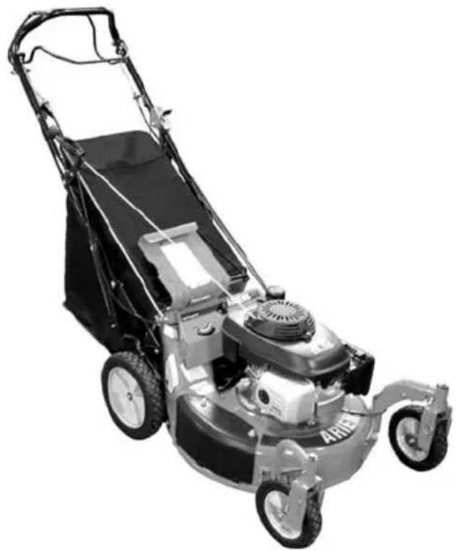
natural_image
Black-and-white photo of a lawn mower with visible blades and wheels (no text or symbols)


ENGLISH

FRANÇAIS

ESPAGNOL
Transfer model & serial number label from product registration here.
| Safety | 5 |
| Assembly | 9 |
| Controls and Features | 10 |
| Operation | 1 |
| Maintenance | 16 |
| Service and Adjustments | 18 |
| Storage. | 22 |
| Troubleshooting | 22 |
| Service Parts | 24 |
| Accessories | 24 |
| Specifications | 25 |
| Warranty | 27 |
INTRODUCTION
THE MANUAL
Before using the unit, carefully and completely read your manuals. The contents will give you an understanding of safety instructions and controls during normal operation and maintenance.
All reference to left, right, front, or rear are given from the operator's position, facing the direction of forward travel.
SERVICE AND REPLACEMENT PARTS
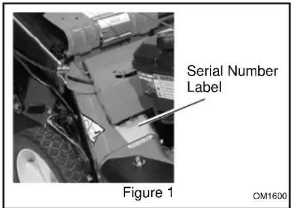
When ordering replacement parts or making service inquiries, know the Model and Serial numbers of your unit and engine.
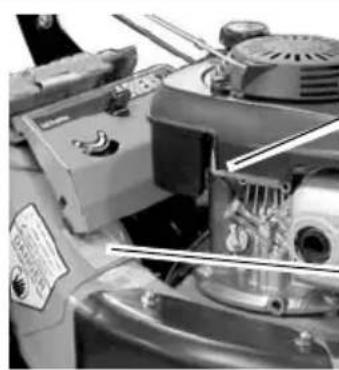
Numbers are located on the product registration form in the unit literature package. They are also printed on a serial number label, located on the frame of your unit (Figure 1 and Figure 2).
natural_image
Close-up of a mechanical assembly with visible components and a label (no readable text or symbols)Engine Serial Number Label
Unit Serial Number Label
Figure 2
- Record Unit Model and Serial numbers here:
- Record Engine Model & Serial numbers here:
PRODUCT REGISTRATION
The Ariens dealer must register the product at the time of purchase. Registering the product will help the company process warranty claims or contact you with the latest service information. All claims meeting requirements during the limited warranty period will be honored, whether or not the product registration card is returned. Keep a proof of purchase if you do not register your unit.
Customer Note: If the Dealer does not register your product, please fill out, sign and return the product registration card to Ariens or go to www.ariens.com on the internet.
UNAUTHORIZED REPLACEMENT PARTS
Use only Ariens replacement parts. Replacing any part on this vehicle with anything other than an Ariens authorized replacement part may adversely affect the performance, durability, or safety of this unit and may void the warranty. Ariens disclaims liability for any claims or damages, whether warranty, property damage, personal injury or death arising out of the use of unauthorized replacement parts. To locate your nearest Ariens Dealer, call 1-800-678-5443 or go to www.ariens.com on the internet.
DEALER DELIVERY
Dealer should:
- Check that all assembly and adjustments have been properly completed.
-
Fill out Original Purchaser Registration Card and return the card to Ariens.
-
Explain Ariens Limited Warranty Policy.
- Explain recommended lubrication and maintenance. Advise customer on adjustments. Remind customer to change oil in 4 cycle engine crankcase after first five (5) hours of operation.
- Instruct customer on controls and operation of unit. Discuss and emphasize the Safety Rules. Give customer Owner/Operator, Parts, and Engine manuals. Advise customer to thoroughly read and understand them.
DISCLAIMER
Ariens reserves the right to discontinue, make changes to, and add improvements upon its products at any time without public notice or obligation. The descriptions and specifications contained in this manual were in effect at printing. Equipment described within this manual may be optional. Some illustrations may not apply to your unit.
SAFETY

WARNING: This cutting machine is capable of amputating hands and feet and throwing objects. Failure to observe the safety instructions in the manuals and on decals could result in serious injury or death.
Slopes are a major factor related to slip and fall accidents.
Operation on all slopes requires extra caution.
Tragic accidents can occur if the operator is not alert to the presence of children. Never assume that children will remain where you last saw them.
Gasoline is extremely flammable and the vapors are explosive, handle with care.
Stop unit and engine, remove key (if equipped) and allow moving parts to stop before leaving operator's position.
SAFETY ALERTS

Look for these symbols to point out important safety precautions. They mean:

Attention!
Personal Safety Is Involved! Become Alert!
Obey The Message!
The safety alert symbols above and signal words below are used on decals and in this manual.
Read and understand all safety messages.

DANGER: IMMINENTLY HAZARDOUS SITUATION! If not avoided, WILL RESULT in death or serious injury.

WARNING: POTENTIALLY HAZARDOUS SITUATION! If not avoided, COULD RESULT in death or serious injury.

CAUTION: POTENTIALLY HAZARDOUS SITUATION! If not avoided, MAY RESULT in minor or moderate injury. It may also be used to alert against unsafe practices.
NOTATIONS
NOTE: General reference information for proper operation and maintenance practices.
IMPORTANT: Specific procedures or information required to prevent damage to unit or attachment.
PRACTICES AND LAWS
Practice usual and customary safe working precautions, for the benefit of yourself and others. Understand and follow all safety messages. Be alert to unsafe conditions and the possibility of minor, moderate, or serious injury or death. Learn applicable rules and laws in your area.
Original purchaser of this unit was instructed by the seller on safe and proper operation. If anyone other than the original purchaser will use the unit, ALWAYS provide this manual and any needed safety training before operation.
SAFETY DECALS AND LOCATIONS
ALWAYS replace missing or damaged safety decals. Refer to Figure 3 for safety decal locations.
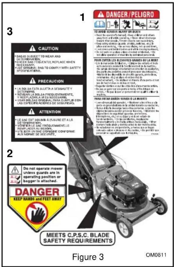
1. DANGER!
TO AVOID SERIOUS INJURY OR DEATH

OL1801
Read the operator's manual.
OL4370
Keep children and others away from unit while operating.

OL0910
Never direct discharge toward other people. Thrown objects can cause injury.
OL4540
Do not operate mower unless guards are in operating position or entire bagger is attached.

OL3030
Keep safety devices (guards, shields, switches, etc.) in place and working.
- Go across slopes, not up and down.
- Look down and behind before and while moving backward.
- Do not park on a slope unless chocked or blocked.
- Do not allow operation of machine by untrained personnel.
2. DANGER!
KEEP HANDS AND FEET AWAY
Do not operate mower unless guards are in operating position or bagger is attached.
3. CAUTION!
- Bag is subject to wear and deterioration.
- Check bag frequently, replace when necessary.
- Use original bag to comply with safety specifications.
SAFETY RULES
If unit is to be used by someone other than original purchaser; loaned, rented or sold, ALWAYS provide this manual and any needed safety training before operation.
Read, understand and follow all safety practices in Owner/Operator Manual before beginning assembly. Failure to follow instructions could result in personal injury and/or damage to unit.
ALWAYS remove key (if equipped) and disconnect wire from spark plug before assembly. Unintentional engine start up can cause death or serious injury.
Complete a walk around inspection of unit and work area to understand:
- work area
- your unit
- all safety decals.
Clear work area of stones, sticks, wire and foreign objects which might be picked up and thrown. Tall grass can hide obstacles.
Know the work area. Stay alert for holes, rocks, rough terrain and hidden hazards.
Keep away from drop-offs, ditches, or embankments that could cause operator to lose footing or control of unit.
ALWAYS be aware of traffic when operating along streets or curbs.
Keep work area clear of all persons, children and pets.
Keep children out of the work area and under the watchful care of a responsible adult.
ALWAYS operate unit when there is good visibility and light.
DO NOT mow wet grass.
ALWAYS be sure of your footing. Keep a firm hold on handlebar. Walk, NEVER run.
Engine/blade control feature on mower stops engine and blade within 3 seconds whenever operator releases handlebar. Check this feature frequently. If feature fails to operate, disconnect spark plug wire and adjust or have it repaired before using unit.
Only trained adults may operate unit. Training includes actual operation.
NEVER operate after or during the use of medication, drugs or alcohol. Unit requires complete and unimpaired attention.
NEVER allow children to use mower.
ALWAYS keep hands and feet away from rotating parts. Rotating parts can cut off body parts.
ALWAYS keep hands away from pinch points.
Fumes from engine exhaust can cause death or serious injury. DO NOT run engine in an enclosed area.
ALWAYS protect eyes, face, and body with adequate safety gear and protective clothes. Wear sturdy footwear, gloves and safety goggles or safety glasses with side shields while operating mower.
NEVER operate mower barefoot or when wearing open sandals or canvas shoes.
NEVER wear loose clothes, long hair or jewelry that may get caught in rotating parts.
ALWAYS stand clear of discharge when operating unit.
NEVER direct discharge toward bystanders.
Operator is responsible for bystander safety.
DO NOT touch hot parts. Allow parts to cool.
Keep safety devices or guards in place and functioning properly. NEVER modify or remove safety devices.
Read, understand, and follow all instructions in the manual and on the machine before starting. Understand:
• How to operate all controls
• The functions of all controls
• How to STOP in an emergency.
DO NOT attempt to start your engine until you know what the controls do and how they work.
DO NOT tilt mower when starting it.
Keep feet away when starting engine.
DO NOT start the engine or operate mower without side discharge cover or side discharge deflector installed.
Take all possible precautions when leaving unit unattended.
ALWAYS shut off engine, remove key (electric start models) and disconnect spark plug wire to prevent accidental starting or unauthorized use.
Stop engine if anyone enters the work area.
NEVER attempt to make any adjustments to unit while engine is running (except where specifically recommended). Stop engine, remove key (electric start models) and wait for all moving parts to stop before servicing.
DO NOT make cutting height wheel adjustments while the engine is running.
If you strike an object, or if equipment vibrates abnormally, stop engine at once, wait for moving parts to stop and disconnect wire from spark plug. Repair any damage before restarting unit.
Keep rear door closed when engine is running unless the grass bag is in place.
Stop engine before removing and emptying grass bag.
When mulching or bagging, ALWAYS install discharge cover.
When side discharging, ALWAYS install side discharge deflector.
ALWAYS shut off engine, allow blade to stop and disconnect spark plug wire before clearing clogs or cleaning unit.
Check grass bag for wear, damage, and/or deterioration. Replace only with Ariens original equipment replacement parts for safety.
To reduce fire hazard and overheating, keep equipment free of grass, leaves, debris or excessive lubricants.
Use extra care when approaching blind corners, shrubs, trees, or other objects which may obscure vision.
DO NOT mow at too fast a rate. DO NOT change engine governor setting or over-speed the engine.
Do not operate mower on gravel or loose material such as sand. Stop mower when crossing drives, walks, or roads to prevent damage or injury from thrown objects.
DO NOT pull mower backwards unless absolutely necessary. Look down and back, especially for small children, before and while moving backwards.
Releasing wheel drive control must stop mower's forward movement. If this feature fails to operate, disconnect spark plug wire and repair before using unit.
On self-propelled models, wheel drive must be disengaged when starting engine.
DO NOT operate on steep slopes.
NEVER leave unit unattended on a slope. Chock wheels if parking on a slope.
Mow across the face of slopes, never up and down. Be especially cautious when changing direction on slopes.
This product is equipped with an internal combustion engine. DO NOT use on or near any unimproved, forest or brush covered land unless the exhaust system is equipped with a spark arrestor meeting applicable local, state or federal laws. A spark arrestor, if used, must be maintained in effective working order by the operator. See your Ariens Dealer or engine manufacturer's service center.
Fuel is highly flammable and its vapors can explode. ONLY use approved fuel containers.
- NO Smoking!
- NO Sparks!
- NO Flames!
- Allow engine to cool before filling fuel tank.
Never fill containers inside a vehicle or on a truck or trailer bed with a plastic liner. Always place containers on the ground away from your vehicle before filling.
When practical, remove gas-powered equipment from the truck or trailer and refuel it on the ground. If this is not possible, then refuel such equipment on a trailer with a portable container, rather than from a gasoline dispenser nozzle.
Keep the nozzle in contact with the rim of the fuel tank or container opening at all times until fueling is complete. Do not use a nozzle lock-open device.
Check fuel supply before starting engine.
DO NOT fill gasoline tank indoors, when engine is running, or while engine is hot.
Allow engine to cool several minutes before removing fuel cap.
DO NOT overfill. Allow about 1/4" (6 mm) of tank space for fuel expansion.
Replace gasoline tank cap securely and clean any spilled fuel before starting engine. If fuel is spilled on clothing, change clothing immediately.
NEVER store fuel inside where there is an open flame, such as a water heater.
ALWAYS drain fuel outdoors away from ignition sources.
ALWAYS shut off engine, and remove key, and close fuel shutoff valve when transporting unit on a truck or trailer.
Avoid Electric Shock. DO NOT disconnect wire from spark plug while engine is running. Do NOT put battery in fire or mutilate.
Explosive Gases!
NO flames, NO sparks, NO smoking, near battery.
Poisonous battery fluid contains sulfuric acid. Contact with skin, eyes or clothing can cause severe chemical burns.
ALWAYS wear safety glasses and protective gear near battery.
ALWAYS keep batteries out of reach of children.
Battery posts, terminals and related accessories contain lead and lead compounds, chemicals known to the State of California to cause cancer and reproductive harm. Wash hands after handling.
Accidental engine start up can cause death or serious injury. Except where specifically recommended, ALWAYS stop engine, remove key (electric start models), wait for moving parts to stop, allow parts to cool and disconnect spark plug wire before inspecting, servicing, adjusting or repairing unit.
Keep mower free of grass, leaves, or other debris build-up.
Keep equipment in good condition.
Maintain or replace safety and instruction labels, as necessary.
Follow engine manufacturer's safety instruction when servicing engine.
Check all hardware at regular intervals, especially blade attachment bolts. Keep all hardware properly tightened.
Before tipping unit, remove fuel and battery (if equipped).
Ensure all wheel blocks, jack stands and tie downs will support unit during maintenance. Replace worn-out mufflers immediately. Continued use could result in fire or explosion.
Sharp edges can cut or amputate fingers or a hand. Wrap blade or wear sturdy gloves to service.
Use only replacement parts designed for your unit. See your Ariens Dealer.
Allow engine to cool before storing in any enclosure.
ALWAYS clean unit before extended storage. See engine manual for proper storage.
DO NOT store unit inside a building with fuel in the fuel tank where any ignition sources are present.
Use only accessories which have been approved by Ariens and are properly installed.
Check attachments frequently and replace worn or damaged components with manufacturer's recommended parts.
ASSEMBLY

CAUTION: AVOID INJURY. Read and understand the entire Safety section before proceeding.
CARTON CONTENTS
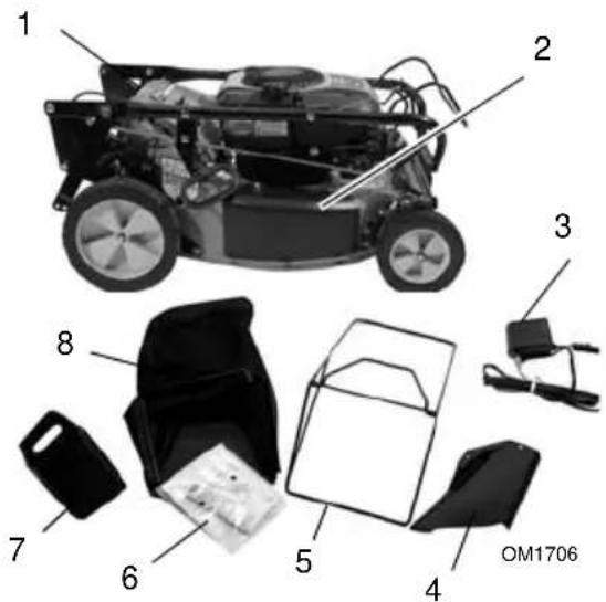
- Mower Unit
- Side Discharge Cover
- Battery Charger (911331, 515)
- Side Discharge Deflector
- Grass Bag Frame
- Literature Pack
- Mulch Plug
- Grass Bag
Figure 4
ASSEMBLY
- Unfold and adjust handlebar. See Handlebar Height on page 19.
NOTE: DO NOT bend the speed control rod (if equipped) when unfolding the handlebars.
- Fill engine crankcase with oil. See engine manual.
- Set-up mower for bagging, side discharge or mulching. See Mower Set-Up on page 14.
- Fully charge battery (electric start models). See To Charge Battery on page 19.
- Fill fuel tank. See Filling Fuel Tank on page 14.
-
Connect spark plug wire.
-
Check the engine/blade control feature. Try starting the engine without the engine/blade control held against the handlebar. Engine must not start. If engine starts, stop engine and adjust or repair engine/blade control. See Engine/Blade Control Adjustment on page 20.
CONTROLS AND FEATURES
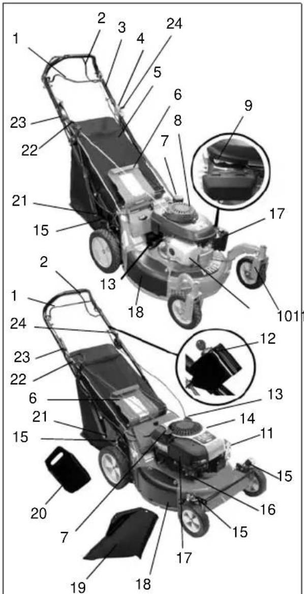
Figure 5
OM1687
- Engine/Blade Control
- Wheel Drive Control
- Adjustable and Folding Handlebars
- Swivel Wheel Lock (911100) (911101, 330, 525)
- Grass Bag
- Rear Door
- Fuel Tank and Cap
- Fuel Shutoff Valve (911099, 101, 102)
- Choke Lever (911099, 101)
- Height Adjustment Pins (911101, 330, 525)
- Muffler and Muffler Guard
- Ignition Switch (911515)
- Oil Fill/Dipstick
- Oil Filter (911526)
- Cutting Height Levers (2 Rear Wheel Adjusters, 2 Front Wheel Adjusters)
- Primer Bulb (911330, 331, 514, 515, 525, 526, 531)
- Air Filter
- Side Discharge Cover
- Side Discharge Deflector
- Mulchmaster™ Plug
- Handlebar Adjustment Holes
- Recoil Starter Handle
- Speed Control Rod
- Throttle Control (911102, 526)
OPERATION
CONTROLS AND FEATURES
See Figure 5 for locations.

WARNING: Improper operation can lead to injury. Learn what the controls do and how they work. Thoroughly read and understand entire Operator Manual.

CAUTION: AVOID INJURY. Read and understand the entire Safety section before proceeding.
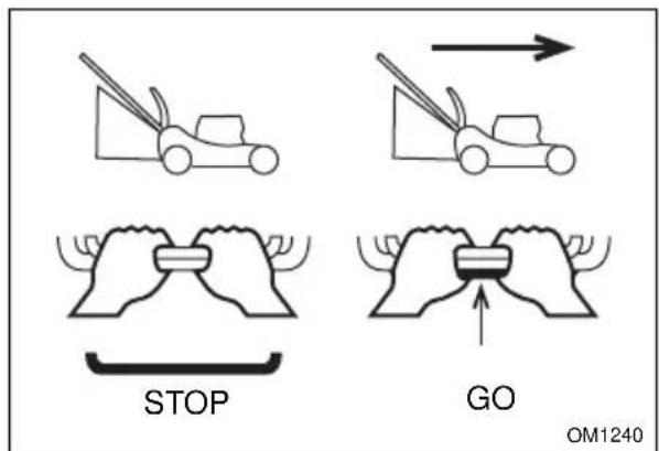
Engine/Blade Control

CAUTION: Check function of Engine/Blade Control regularly. Improper function of control could cause injury.
The engine/blade control must be held against the handlebar to start the engine and blade.
Engine/blade control feature on mower stops engine and blade within 3 seconds whenever operator releases handlebar. Check this feature frequently. If feature fails to operate, disconnect spark plug wire and adjust or have it repaired before using unit.

natural_image
Two identical line drawings of hands holding a tool, with no text or symbols present.STOP START and RUN
OM1230
Handlebar
Adjust handlebar to a safe and comfortable height. See Handlebar Height on page 19.
Recoil Starter Handle
When pulled, handle will turn engine over.
CUTTING HEIGHT ADJUSTMENT

DANGER: Avoid injury from rotating blade.
ALWAYS shut off engine before adjusting cutting height.

CAUTION: On self-propelled models, both rear wheels must be set at same height or traction drive may not work properly.
Cutting Height Settings Chart
| Notch Cut grass length | |
| LOW 1" (25 mm) | |
| 2 1-3/8" (35 mm) | |
| 3 1-3/4" (45 mm) | |
| 4 2-1/4" (57 mm) | |
| 5 2-3/4" (70 mm) | |
| HIGH 3-1/4" (83 mm) |
Standard Models
To change cutting height, move cutting height levers one notch at a time on each wheel to set desired height (Figure 6).
NOTE: Each wheel on mower must be set at the same height for a level cut.
High
Rear
- Cutting Height Lever
Front
OM0165
Figure 6
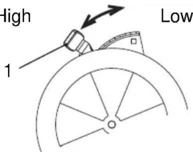
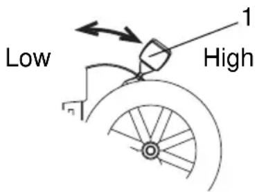
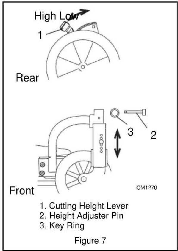
Swivel Wheel Models (911101, 330, 525)
To change front wheel cutting height, insert height adjuster pin into the holes that match the desired cutting height and fasten with key ring (Figure 7).
To change rear wheel cutting height, move cutting height levers one notch at a time to set the desired cutting height.
OPTIONAL CONTROLS
Primer Bulb (911330, 331, 514, 515, 525, 526, 531)
Push the primer bulb in to add fuel for easier engine start.
Choke Control (911099, 101)

natural_image
Simple black arrow pointing right and a vertical line with a small circle on the right (no text or symbols)Move choke lever to the choke position to start a cold engine.
Throttle (911102)
The throttle controls the engine speed and chokes engine for starting.
- Start - Push lever all the way forward.
2.Fast. - Slow - Pull lever all the way rearward.
Throttle (911526)

The throttle controls the engine speed and chokes engine for starting.
- Start - Push lever all the way forward.
2.Fast.
3.Slow - Pull lever all the way rearward.
Ignition Switch (911331, 515)

A removable key operates the ignition switch. The key will spring back to the "RUN" position.
RUN Position (1): All controls are operable.
START Position (2): Starter turns over the engine.
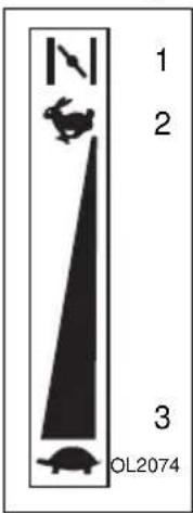
Speed Control
Speed control rod changes the mower's forward travel speeds.

natural_image
Abstract black-and-white graphic with a downward arrow, small fish, and a turtle, labeled 'OM0480' at the bottom (no readable text or symbols in the main graphic)High –Push rod all the way forward.
Low – Pull rod all the way rearward.
Start mowing slowly and use speed control rod to gradually increase speed to a safe, comfortable walking pace.
Speed control rod should hold the desired speed. If not, adjust speed control bell crank. (See Speed Control Bell Crank on page 22.)
Wheel Drive Control

CAUTION: Unit will move forward at engine start if wheel drive control is engaged. ALWAYS release wheel drive control before starting unit.
NOTE: Engine must be running for wheel drive to propel unit.
To drive forward:
Slowly squeeze and hold wheel drive control against handlebar.
To stop:
Release wheel drive control.
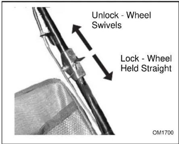
Swivel Wheel Lock (911101, 330, 525)

CAUTION: Avoid loss of control.
Lock swivel wheels when mowing on a slope or hill. Do not mow on steep slopes.
To hold wheel straight:
- Push swivel wheel lock forward.
- Push unit forward until wheel locks in place.
To allow wheel to swivel:
- Pull swivel wheel lock back.
Fuel Shutoff Valve (911099, 101, 102)
IMPORTANT: The fuel shutoff valve MUST be in the closed position prior to transporting the unit.
Open the fuel shutoff valve to operate the unit. Close the fuel shutoff valve when storing, transporting or servicing the unit.
911102
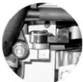
natural_image
Close-up of mechanical components inside a vehicle (no visible text or symbols)Fuel shutoff valve open.
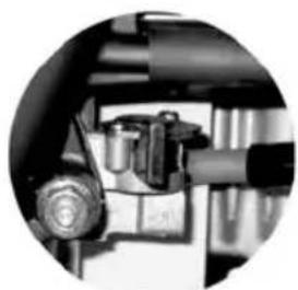
natural_image
Close-up of mechanical components inside a vehicle (no visible text or symbols)Fuel shutoff valve closed.
911099, 101
natural_image
Circular cropped image showing a textured surface with no visible text or symbolsFuel shutoff valve open.
natural_image
Close-up of a mechanical component with textured surfaces and a pointed tip (no visible text or symbols)Fuel shutoff valve closed.
FILLING FUEL TANK
To add fuel to fuel tank:
- Put unit in open or well-ventilated area.
- Stop engine and allow to cool.
- Clean fuel cap and surrounding area.
- Remove cap.
IMPORTANT: See engine manual for correct type and grade of fuel.
- Fill fuel tank. (see Specifications on page 25 for tank capacity.)
- Replace fuel cap and tighten.
- ALWAYS clean any spilled fuel.
MOWER SET-UP

CAUTION: DO NOT operate mower unless either side discharge cover or side discharge deflector is installed. Thrown objects may cause damage or injury. Never operate unit with rear door open unless grass bag is in place.

CAUTION: If clog or obstruction prevents grass flow, release engine/blade control and disconnect spark plug wire before attempting to clear away any clogs.
To Bag

CAUTION: Check grass bag frequently for wear or deterioration. Replace worn or damaged bag with Ariens original equipment replacement bag only.
- Shut off unit.
- Install side discharge cover.
- Lift rear door.
- Hook grass bag frame on mounting flange.
- Lower rear door.
If necessary, lift rear of grass bag frame to lock in position.
There should be no openings between bag and mounting surface after installing bag. If necessary, clear debris from bag mounting surface.
Grass Bag Removal
- Shut off unit.
- Lift rear door.
- Use handle to lift bag off mounting flange.
- Close rear door.
NOTE: Empty grass bag and clean mower pan after each use. DO NOT allow grass clumps or a grass coating to collect inside of grass bag or mower pan. Remove grass bag from mower, wash bag with hose and allow to dry.
To Side Discharge
- Shut off unit.
- Remove grass bag.
- Install Mulchmaster plug (see below).
- Remove side discharge cover and keep hardware.
- Attach side discharge deflector to studs on mower. Make sure deflector covers discharge opening.
- Secure with cover hardware from step 4.
To Mulch
- Shut off unit.
- Remove grass bag and install side discharge cover.
- Open rear door and insert Mulchmaster plug with the beveled face to the left.
- Close rear door.
NOTE: Rear door must close flush.
NOTE: For maximum mulching performance, install the Mulchmaster Mulching Kit. See Accessories.
EMERGENCY STOPPING
To stop the mower in an emergency:
- Release the engine/blade control.
- Release the wheel drive control (self-propelled models).
- Allow all moving parts to stop before leaving operator's position.
STARTING AND SHUT OFF

WARNING: Improper operation can lead to injury. Learn what the controls do and how they work. Thoroughly read and understand entire Operator Manual.
See Figure 5 for all Controls and Features.
NOTE: Start engine on a level surface that is free of debris.
Manual Start
Models 911330, 331, 514, 515, 525, 526, 531
- Check each item under Before Each Use in the Maintenance Schedule on page 16.
- For engines with a primer, push primer bulb 2 or 3 times for a cold engine.
NOTE: It is unnecessary to prime or choke a warm engine.
- For engines with a throttle, place throttle control in the choke position. Once the engine has started, place throttle in the high speed detent.
- With engine/blade control held against the handlebar, grasp starter handle and pull rope slowly until it pulls harder. This is the compression stroke. Let rope rewind slowly.
- Pull rope with rapid continuous full arm stroke to start engine. Allow rope to rewind slowly.
IMPORTANT: DO NOT let starter handle snap against bracket.
- Repeat steps 4 and 5 until engine starts. (If engine does not start, see Troubleshooting on page 22.)
Models 911099, 101, 102
- Check each item under Before Each Use in the Maintenance Schedule on page 16.
- Open the fuel shut-off valve.
NOTE: It is unnecessary to choke a warm engine.
- Move the choke lever to the choke position.
The choke lever automatically returns to the Off position when the engine/blade control is held against the handlebar (911099, 101). - With engine/blade control held against the handlebar, grasp starter handle and pull rope slowly until it pulls harder. This is the compression stroke. Let rope rewind slowly.
- Pull rope with rapid continuous full arm stroke to start engine. Allow rope to rewind slowly.
IMPORTANT: DO NOT let starter handle snap against bracket.
- Repeat steps 4 and 5 until engine starts. If engine does not start, release the engine/blade control and perform steps 2 through 5. See engine manual for detailed instructions.
- After engine starts, put throttle control in the Fast position (911102).
Electric Start (911331, 515)
NOTE: Recoil may also be used to start the engine (see Manual Start on page 15).
- Check each item under Before Each Use in the Maintenance Schedule.
- Push primer bulb 2 or 3 times for a cold engine.
NOTE: It is unnecessary to prime or choke a warm engine.
- With engine/blade control held against the handlebar, turn the key to "Start" position to crank engine and release key when engine starts.
IMPORTANT: Do not run starter continuously for more than fifteen seconds. If the engine does not start after several attempts, refer to Troubleshooting.
Shut Off
- Release wheel drive control and allow unit to stop completely.
- Release engine/blade control.
- Remove key (electric start models).
Mowing Tips
Cut grass when it is dry.
Keep mower blades sharp.
Do not set cutting height too low. For tall grass, mow twice.
Do not mow too fast.
Mow with engine at full throttle. Discharge clippings into areas already cut.
Vary cutting pattern with each mowing.
NOTE: To prevent dirt and grass from collecting on mower pan, avoid operating over bare ground with only patches of grass.
Mulching Tips
For best mulching performance, cut no more than 1 inch (2.54 cm) of grass per cutting.
MAINTENANCE

CAUTION: AVOID INJURY. Read and understand the entire Safety section before proceeding.
Ariens Dealers will provide any service, parts or adjustments which may be required to keep your unit operating at peak efficiency. Should engine require service, contact an Ariens Dealer or an authorized engine manufacturer's service center.
MAINTENANCE SCHEDULE
NOTE: Some working conditions (heavy loads, high ambient temperatures, dusty conditions, or airborne debris) may require more frequent service.
See engine manual for further maintenance and troubleshooting information.
MAINTENANCE SCHEDULE
| Service Performed | Before Each Use | 25 100 | |
| Check Engine/Blade Control | • | ||
| Check Wheel Drive Control | • | ||
| Check Grass Bag • | |||
| Clean Unit • | |||
| Check Engine Oil • | |||
| Check Mower Blade • | |||
| Check Drive Belt • | |||
| Check Fasteners • | |||
| Check Air Cleaner • | |||
| Change Engine Oil | •* | ||
| General Lubrication • | |||
| Replace Oil Filter • | |||
| Check Spark Plug • | |||
| Check Engine Cooling | • | ||
| Check Muffler | • | ||
* After first 5 Hours of operation
CHECK ENGINE/BLADE CONTROL
The engine and blade must stop within 3 seconds after releasing the control. If the engine and blade continue to run, adjust or repair control immediately. See Engine/Blade Control Adjustment on page 20.
CHECK WHEEL DRIVE CONTROL
The unit must stop quickly and completely when the control is released. Adjust or repair if necessary. See Wheel Drive Control Adjustment on page 21.
CHECK GRASS BAG
Check grass bag frequently for wear or deterioration. Replace worn or damaged bag with Ariens original equipment replacement bag only.
CLEAN UNIT
Before each use clean unit, muffler and engine surfaces of debris, oil or fuel spills to ensure proper cooling and prevent fires.
CHECK ENGINE OIL
IMPORTANT: Maintain proper oil level at all times or engine damage will result.
Check the level of the engine crankcase oil before each use.
Make sure engine is level when checking oil. See engine manual for instructions.
CHECK MOWER BLADE
See Figure 8.
Check blade mounting: blade must be secure and bolt torqued to 37.5 - 50 lbf-ft (51-68 N•m) (bolt should fully compress lock washer).
Check blade for nicks and dull cutting edges. Sharpen if necessary.
Check blade for rounded or broken ends, thinned metal or other damage. Replace if necessary.
NOTE: Blades should be sharpened and balanced professionally. Contact your Ariens Dealer.
To remove blade:
- Stop engine, wait for all moving parts to stop, and disconnect spark plug wire.
- Block blade to prevent rotation.
- Remove bolt, lock washer, flat washer and blade from shaft.
To install blade:
- Replace blade, flat washer, lock washer and bolt on shaft.
-
Torque bolt to 37.5 - 50 lbf-ft (51-68 N·m) (bolt should fully compress lock washer).
-
Connect spark plug wire.
Sharpen the Mower Blades

CAUTION: DO NOT sharpen mower blades while on unit. An imbalanced mower blade will cause excessive vibration and eventual damage to unit. Check mower blade balance before reinstalling blades. NEVER weld or straighten bent blades.
- Remove mower blade from unit.
Discard mower blade if:
- More than 1/2 in. (1.27 cm) of metal is removed.
• Air lifts become eroded. - Blade is bent or broken.
- Sharpen mower blade by removing an equal amount of material from each end of mower blade. DO NOT change angle of cutting edge or round the corner of the mower blade.
DO NOT Sharpen to This Pattern
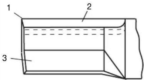
DISCARD if More Than
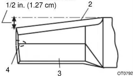
Sharpen to This Pattern
- Square Corner
- Cutting Edge
- Air Lift
- Air Lift Erosion
Figure 8
- Check mower blade balance.
Slide mower blade on an unthreaded bolt. A balanced blade should remain in a horizontal position. If either end of mower blade moves downward, sharpen the heavy end until blade is balanced (Figure 9). - Install mower blade on unit.
- Tighten the bolts to a torque of 37.5 - 50 lbf-ft (51-68 N·m).
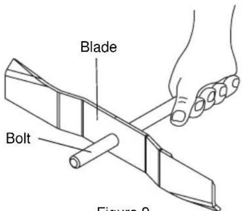
Figure 9
OA0013
CHECK DRIVE BELT
Check drive belt and replace if worn or damaged. See Drive Belt Replacement on page 21.
CHECK FASTENERS
Check all fasteners for proper tightness. Pay special attention to blade hardware and all guards, shields and safety devices.
CHECK AIR CLEANER
See engine manual for specific information.
CHANGE ENGINE OIL
IMPORTANT: Change engine crankcase oil after first five (5) hours of operation. Then change oil after every 25 hours of operation.
Refer to engine manual for instructions and proper oil type.
IMPORTANT: Proper oil level must be maintained at all times or engine damage will result. DO NOT overfill. Be sure engine is level when adding oil.
GENERAL LUBRICATION
NOTE: LM21SCH and LM21SC have lube fittings on drive mount for use in commercial applications. Lubricate as needed.
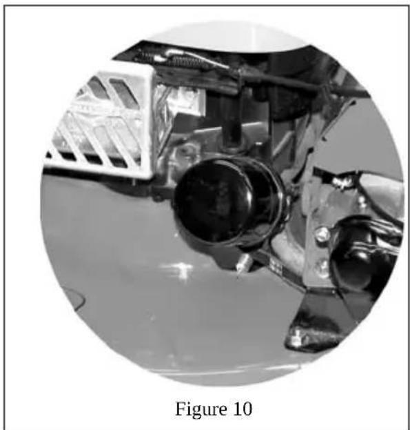
REPLACE OIL FILTER (911526)
Replace oil filter every 100 hours of use or every season.
- Change engine oil.
- Clean around filter.
- Turn filter counterclockwise to remove (Figure 10).
- Apply a thin coat of oil onto seal of new filter.
- Install new filter and hand tighten securely.
natural_image
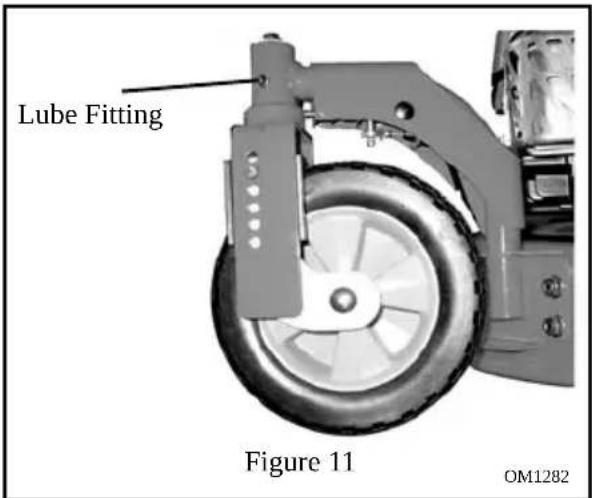
Close-up of a mechanical component with no visible text or symbols, labeled as Figure 10 (no readable text or symbols on the main subject)Swivel Wheels (911101, 330, 525)
See Figure 11.
Use Sten Mix Hi-Temp Grease or equivalent on the lube fittings. Order P/N: 00036800 - 3 pack of 3 oz. cartridges.
CHECK SPARK PLUG
Spark plug should be replaced every 100 hours of operation or each year.
NOTE: Loose spark plug wire terminals can cause sparking. Replace terminal if damaged.
CHECK ENGINE COOLING

WARNING: HOT SURFACES can cause death or serious injury. DO NOT TOUCH parts which are hot from operation. ALWAYS allow parts to cool.
To prevent overheating, air must circulate freely around the cooling fins, cylinder head and block.
Every 100 hours of operation or yearly (more often if conditions require) remove blower housing and clean cooling fins. See engine manual for instructions.
CHECK MUFFLER
Check muffler for debris, cracks, wear, or other damage.

CAUTION: Replace worn-out mufflers immediately. Continued use could result in fire or explosion.
SERVICE AND ADJUSTMENTS

CAUTION: AVOID INJURY. Read and understand the entire Safety section before proceeding.
SERVICE POSITION
Put unit into service position for easy access to underneath the deck.

CAUTION: Avoid fuel spills. Follow steps below to help prevent fuel spills. If fuel leaks into air cleaner, replace air cleaner. ALWAYS clean up any spilled fuel.
- Place unit on a flat, level surface.
- Disconnect spark plug wire.
- Remove fuel cap, place a piece of plastic bag over the opening and tighten cap securely.
- Tip unit onto left side, opposite the discharge opening (911330, 331, 514, 515, 525, 526, 531).
Tip unit onto right side (911099, 101, 102).
Make sure unit is secure and will not tip over.
IMPORTANT: Remove plastic from fuel cap after unit is upright and service is complete.
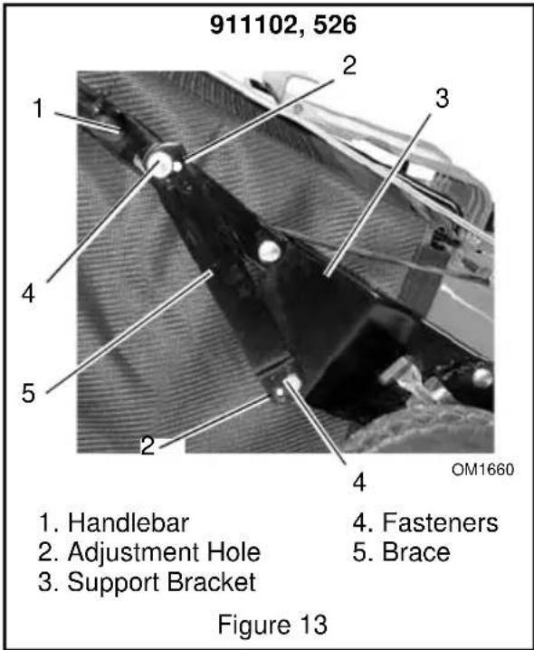
HANDLEBAR HEIGHT
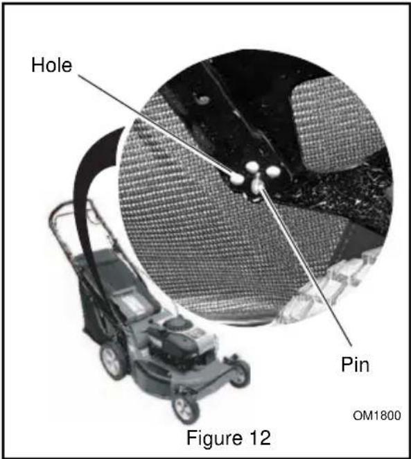
To adjust (Figure 12 and Figure 13):
- Place a hole at the bottom of the braces over the pins on the bracket.
- On 911102 and 526, use the fasteners to attach one of the holes at the top and one of the holes at the bottom.
NOTE: To fold handlebars flat for storage, pull the speed control rod (if equipped) all the way back, disconnect braces from support bracket, and fold handlebar forward. Do not bend speed control rod.
BATTERY (911331, 515)
To Remove Battery from Unit
- Remove drive cover.
- Disconnect battery plug from wiring harness on engine (Figure 14).
- Remove wing nuts from battery U-bolt.
- Remove battery plate and battery.
To Replace Battery on Unit
- Hold battery and battery plate in place against mower frame.
- Secure with U-bolt and wing nuts.
- Reconnect battery plug to wiring harness on engine.
- Replace drive cover.
To Charge Battery
IMPORTANT: DO NOT attempt to "jump start" mower.
- Connect battery charger plug to mating plug on battery (not engine).
IMPORTANT: Your unit shipped with either a 110- or a 220-volt battery charger. Make sure you have the correct charger for your region before charging your battery.
- Plug charger into an appropriate Alternating Current (A.C.) outlet.
- Charge for 24 to 48 hours (battery may be charged for up to 56 hours without damaging it).
At least 8 hours of engine run time are required to charge a fully discharged battery.
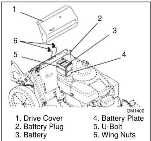
Figure 14
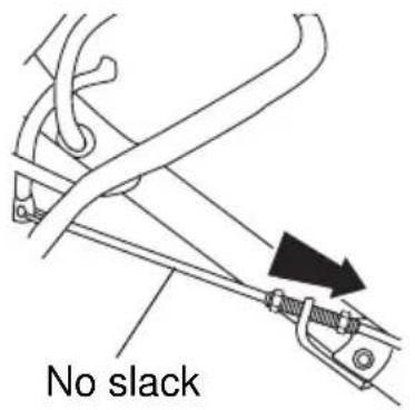
ENGINE/BLADE CONTROL ADJUSTMENT
To adjust engine/blade control:
- Loosen cable nuts away from bracket.
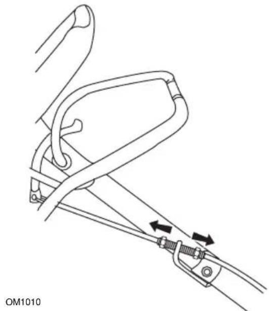
natural_image
Line drawing of a mechanical clamp or bracket assembly with arrows indicating movement (no text or symbols)- Squeeze z-bend bracket at engine end of cable toward front of unit and hold in place.
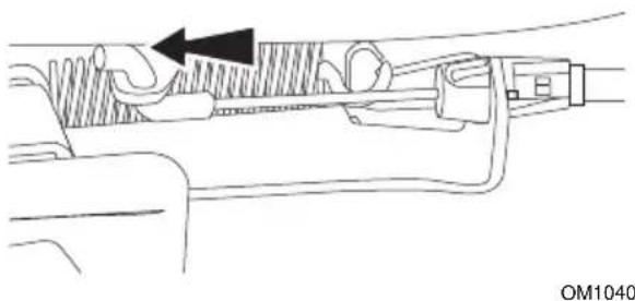
natural_image
Technical diagram of a mechanical component with internal channels and a directional arrow (no text or symbols)- Pull cable down from bracket until there is no slack in cable.
OM1061
- Tighten lower cable nut to 1/8" (3 mm) below bracket. Release z-bend bracket.
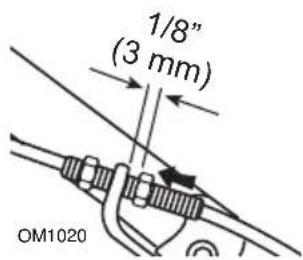
- Tighten upper cable nut until bracket is secure between cable nuts.

natural_image
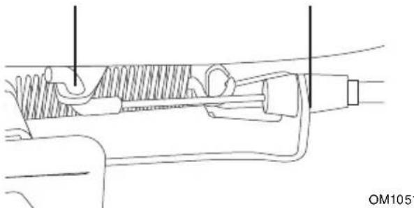
Mechanical diagram showing a clamp or spring mechanism with a directional arrow, labeled 'OM1030' (no text or symbols on the diagram itself)- Engage engine/blade control. Measure distance between middle of z-bend and cable bracket. Measurement should be as shown below.
Briggs Engines:1.325"-1.788" (3.4 cm - 4.5 cm)
Honda Engines: 1.65"-1.69" (4.2 cm - 4.3 cm)
natural_image
Technical line drawing of a mechanical assembly with no visible text or symbols- If correct measurement cannot be set, contact your local dealer.
DRIVE BELT REPLACEMENT
To remove drive belt:
- Disconnect spark plug wire.
- Set the right rear wheel to its lowest cutting height, and the left rear wheel to the third cutting height. This position provides clearance between friction disc and drive sheave.
- Remove belt from the idler, then the drive sheave, and finally, the engine pulley (Figure 15).
- Pull belt through opening under mower pan and over blade.
- Make sure the idler pulley turns and the idler arm moves freely.
- Reinstall drive belt in reverse order.
IMPORTANT: Be sure the belt seats in sheave and pulley grooves with the idler touching the back (flat) side of belt.
- Adjust rear wheels to the same cutting height.
-
Blade
-
Engine Pulley
-
Idler
-
Bolt, Lock Washer & Flat Washer
-
Drive Sheave
-
Drive Belt
Figure 15
WHEEL DRIVE CONTROL ADJUSTMENT
See Figure 16.
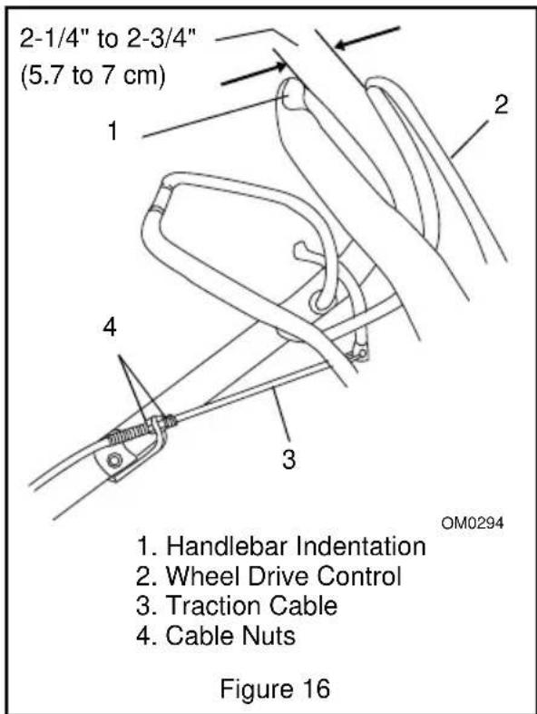
The wheel drive must start to engage when wheel drive control is between 2-1/4" and 2-3/4" (5.7 and 7 cm) away from the handlebar.
To check:
- With engine off, select a slow speed.
- Slowly pull unit backwards.
- Slowly squeeze wheel drive control until wheels stop.
- Measure the distance between the wheel drive control and handlebar at the handlebar indentation.
To adjust:
- If the measurement is more than 2-3/4" (7 cm), loosen the lower cable nut and then tighten the upper cable nut against the adjuster bracket.
- If the measurement is less than 2-1/4" (5.7 cm), loosen the upper cable nut and then tighten the lower nut against the adjuster bracket.
- Recheck measurement with the slowest and fastest speeds selected.
- Repeat adjustment until wheel drive control is properly adjusted.
IMPORTANT: If there is not enough thread length for proper adjustment, contact your Dealer for repairs before operating unit.
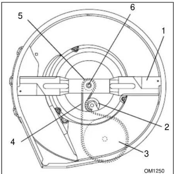
SPEED CONTROL BELL CRANK
The speed control bell crank holds the speed control rod in position after a speed has been set. The spring washers may become loose with normal wear. If the speed control rod does not stay firmly in position, adjust the speed control bell crank. See Figure 17.
To adjust:
- Remove cover, fully compress the helical spring lock washers with lock nut and then back lock nut off, one quarter turn.
- If the speed control rod is still too loose, tighten lock nut by small increments until it holds its position. Tightening the lock nut too much will not allow the speed control rod to move at all.
- Align notch in left hand side of cover with bolt and secure with knob.
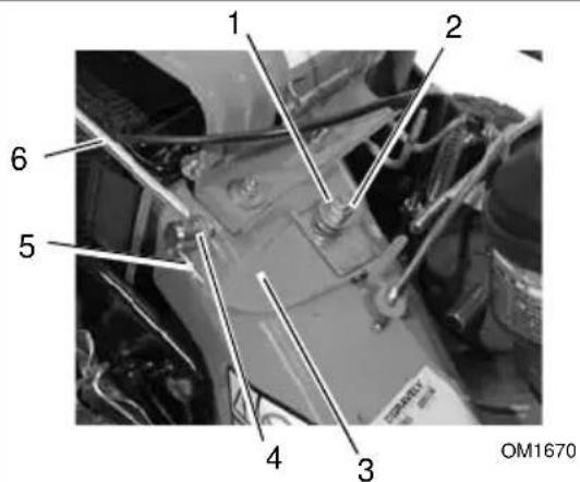
- Lock Nut
- Helical Spring Lock Washers
-
Speed Control Bell Crank
-
Swivel
- Hair Pin
- Speed Control Rod
Figure 17
STORAGE

CAUTION: AVOID INJURY. Read and understand the entire Safety section before proceeding.
IMPORTANT: NEVER spray unit with high-pressure water or store unit outdoors. Store mower in a cool, dry, protected location.
Cleaning
Clean unit thoroughly with mild soap and low pressure water. Brush off dirt and debris from all surfaces. Touch up all scratched surfaces to prevent rust. Matching touch-up paint is available from your Ariens Dealer. Do not use abrasives, solvents, or harsh cleaners.
Inspection
Inspect mower and repair or replace worn or damaged parts to avoid delays when beginning use again.
Regularly check all hardware and keep fasteners tight. Know unit is in safe working condition.
Grass Bag
Wash out grass bag and allow to dry before storage. Grass bag may be stored in position on mower.
Battery
Fully charge battery and store in a cool, dry location. See Service and Adjustments.
IMPORTANT: Do not allow battery to freeze.
Engine
Close fuel shutoff valve (911099, 101, 102).
When storing unit for extended periods of time, remove all fuel from tank and carburetor (run dry). Refer to engine manual.
TROUBLESHOOTING
| PROBLEM PRO | BABLE CAUSE CORRECTION | |
| Engine will not start | Fuel tank empty or low.Fuel shutoff valve closed.Spark plug wire loose or off.Battery discharged (electric start models).Throttle control not in proper position.Engine/Blade control cable detached, broken, or not adjusted properly. | Check fuel level. Fill tank if necessary.Open fuel shutoff valve.Check connection.Charge battery or replace if necessary.Adjust throttle to FAST position.Check cable. Adjust, repair or replace as necessary. |
| Engine is difficult to restart | 1. Mower clogged with grass. 1. Clear clippings from under mower. (Allow the mower to clear clippings before shutting off engine.) | |
| Cut is poor | 1. Worn blade.2. Too much grass is being removed per cutting.3. Grass is too wet.4. Mowing speed is too fast. | 1. Check blade (seeCheck Mower Bladeon page 16).2. Raise cutting height.3. Allow grass to dry.4. Mow slower. |
| Grass does not disperse evenly | 1. Too much grass is being removed per cutting.2. Grass is too wet.3. Mowing speed is too fast. | 1. Raise cutting height.2. Allow grass to dry.3. Mow slower. |
| Mower does not bag clippings | 1. Grass bag is overfilled.2. Mulching plug is installed. | 1. Empty grass bag and do not allow it to overfill.2. Remove mulching plug. |
| Wheel drive does not engage | 1. Wheel drive control not engaged.2. Drive belt out of position.3. Drive belt worn or damaged.4. Rear wheels in different cutting heights.5. Idler spring detached.6. Wheel drive control cable detached or broken.7. Friction disc not adjusted properly or damaged.8. Bearings damaged.9. Debris in gear set. | 1. Engage wheel drive control.2. Check drive belt. Adjust as necessary (seeCheck Drive Belton page 17).3. Replace belt (seeCheck Drive Belton page 17).4. Adjust rear wheels to same cutting height (seeCutting Height Adjustmenton page 11).5. Attach idler spring to notch on idler arm. Contact your Dealer.6. Check wheel drive control cable. Adjust or replace as needed. SeeCheck Wheel Drive Controlon page 16.7. Contact your Dealer.8. Contact your Dealer.9. Contact your Dealer. |
SERVICE PARTS
| Always use genuine Ariens parts to keep your mower running like new. | |
| Description Part Number | |
| Air Filter 215 | 35600 (911331, 514, 515, 525, 526)21529800 (911330, 531)21540500 (911099, 101, 102) |
| Oil Filter 082 | 66101 (911526) |
| Spark Plug 2 | 1534100 (911331, 514, 515, 525, 526)21534300 (911330, 531)21540400 (911099, 101, 102) |
| Blade 01137 | 00001176700 (911330) |
| Battery 5110 | 6400 (911331, 515) |
| Drive Belt 07 | 217100 |
| Friction Disc | 51102500 (911099, 101, 330, 331, 514, 515, 525, 531)03248300 (911102, 526) |
ACCESSORIES
| See your authorized Ariens Dealer to add these optional accessories. | |
| 71102400 Dethatcher | |
| 71102700 Mulchmaster Plug | |
| 71103000 Grass Bag | |
| 71103200 Rear Discharge Chute | |
| 71103500 Mulchmaster Mulching Kit | |
| 71103700 Leaf Shredder | |
| 71103900 Straight Axle Kit | |
| 71104100 Front Swivel Wheel Kit | |
| 71104300 Battery Charger 110V (911515) | |
| 71104600 Battery Charger 220V (911331) | |
| 71104700 Bag-N-Drag Bagger Kit |
| SPECIFICATIONS | ||||
| Model Number 911099 911101 911102 91 1330 911331 | ||||
| Description LM21SH LM21SWH LM21SCH LM21SW LM21SE | ||||
| Length - in. (cm) 61.5 (156) | ||||
| Height - in. (cm) 38 (96.5) | ||||
| Width - in. (cm) 23 (58.4) | ||||
| Actual Weight - lbs (kg) 100 (45.3) 107 (48.8) 115 (52.2) 105 (45.7) | 102 (46.3) | |||
| Cutting Width- in. (cm) 21 (53.3) | ||||
| Cutting Height - in. (cm) | 6 Positions: 1.00 - 3.25 (2.5 - 8.3) | |||
| Engine, 4 cycle | Honda OHC | Honda OHV | Briggs & Stratton Quantum | Briggs & Stratton Intek OHV |
| Model | GCV160 | GXV160 | 123K02 | 126607 |
| Trim | AS1A | KA12 | 0120E1 | 0162E1 |
| Engine Power - HP (kW) @ Max. Governed RPM | 5.1 (3.8) | 5.5 (4.0) | 3.6 (2.5) | 4.47 (3.33) |
| Max Rotation Speed of Cutting Edge - RPM ( min^-1 ) | 3250 | 3350 | 2900 | 3050 |
| Governed RPM | 3100 ± 150 | 3200 ± 150 | 2800 ±100 | 2950±100 |
| Displacement Cu. In. (cc) | 9.8 (160) | 9.9 (163.4) | 12 (197) | 11.57 (190) |
| Cylinder Bore | Aluminum | Cast Iron Sleeve | Aluminum | |
| Engine Oil Type | See engine manual. | |||
| Crank Case Capacity - Oz. (Liter) | 18.5 (0.55) | 22 (0.65) | 20 (0.59) | |
| Oil System | Splash | Forced/ Splash | Splash | |
| Engine Oil Filter | N/A | |||
| Spark Plug Gap - in. (mm) | 0.028-0.031 (.70-.80) | 0.030 (0.76) | 0.020 (0.51) | |
| Fuel Type | Unleaded | |||
| Fuel Tank Capacity - qt (Liter) | 1.2 (1.1) | 1.06 (1.5) | 1.6 (1.5) | |
| Primer Bulb | N/A | Standard | ||
| Throttle | N/A | |||
| Air Cleaner | Paper Element | Paper Element with Foam | Paper Element | |
| Starting | Recoil | Electric/ Recoil | ||
| Differential | Standard | |||
| Variable Speeds - MPH (km/hr) | 0-4 (0-6.4) | |||
| Mower Deck | 14 Gauge - Stamped Steel | |||
| Front Wheel Dia - in. (cm) | 7.5 (19.1) | |||
| Rear Wheel Dia - in. (cm) | 10.5 (26.7) | |||
| SPECIFICATIONS | |||||
| Model Number 911514 9115 | 5 911525 91 | 1526 91153 | 1 | ||
| Description LM21S LM21SE | LM21SW LM | 21SC LM21S | |||
| Length - in. (cm) 61.5 (156) | |||||
| Height - in. (cm) 38 (96.5) | |||||
| Width - in. (cm) 23 (58.4) | |||||
| Actual Weight - lbs (kg) 97 (44) | 102 (46.3) | 105 (45.7) | 110 (49.9) | 93 (42.2) | |
| Cutting Width- in. (cm) | 21 (53.3) | ||||
| Cutting Height - in. (cm) | 6 Positions: 1.00 - 3.25 (2.5 - 8.3) | ||||
| Engine, 4 cycle | Briggs & Stratton Intek OHV | Briggs & Stratton Quantum | |||
| Model | 126602 | 126607 | 126602 | 122672 | 123K02 |
| Trim | 0146E1 | 0162E1 | 0146E1 | 0211E1 | 0120E1 |
| Engine Power - HP (kW) @ Max. Governed RPM | 4.37 (3.26) | 4.47 (3.33) | 4.37 (3.26) | 4.47 (3.33) | 3.6 (2.5) |
| Max Rotation Speed of Cutting Edge - RPM ( min^1 ) | 2900 | 3050 | 2900 | 2900 | 2900 |
| Governed RPM | 2800±100 | 2950±100 | 2800 ± 100 | 2800±100 | 2800±100 |
| Displacement Cu. In. (cc) | 11.57 (190) | 12 (197) | |||
| Cylinder Bore | Aluminum | Cast Iron Sleeve | Aluminum | ||
| Engine Oil Type | See engine manual. | ||||
| Crank Case Capacity - Oz. (Liter) | 20 (0.59) | ||||
| Oil System | Splash | Pressurized | Splash | ||
| Engine Oil Filter | N/A | Spin-On | N/A | ||
| Spark Plug Gap - in. (mm) | 0.020 (0.51) | ||||
| Fuel Type | Unleaded | ||||
| Fuel Tank Capacity - qt (Liter) | 1.6 (1.5) | ||||
| Primer Bulb | Standard | ||||
| Throttle | N/A | Standard | N/A | ||
| Air Cleaner | Paper Element | ||||
| Starting | Recoil | Electric/Recoil | Recoil | ||
| Differential | Standard | ||||
| Variable Speeds - MPH (km/hr) | 0-4 (0-6.4) | ||||
| Mower Deck | 14 Gauge - Stamped Steel | ||||
| Front Wheel Dia - in. (cm) | 7.5 (19.1) | ||||
| Rear Wheel Dia - in. (cm) | 10.5 (26.7) | ||||

Ariens Company
655 West Ryan Street
P.O. Box 157
Brillion, WI 54110-0157
920-756-2141
Fax 920-756-2407
www.ariens.com
2-Year Limited Warranty
Ariens Company warrants to the original purchaser that consumer products manufactured by Ariens Company will be free from defects in material and workmanship for a period of two (2) years after the date of purchase, and will repair any defect in material or workmanship, and repair or replace any defective part, subject to the conditions, limitations and exclusions set forth herein.
The two-year duration of this warranty applies only if the product is put to ordinary, reasonable, and usual personal, family, or household uses. If the product is put to any business, commercial, or industrial use such as, but not limited to, commercial landscaping, mowing or snow removal services, or golf course or park maintenance, or agricultural or farmstead use, then the duration of this warranty is ninety (90) days after the date of purchase, or one (1) year after the date of purchase if the product is labeled as a Professional/Commercial Product. If any product is rented or leased, then the duration of this warranty is ninety (90) days after the date of purchase.
Genuine Ariens service parts and accessories not purchased with the product covered by this warranty, but which are later purchased and used with that product, are warranted to be free from defects in material and workmanship for a period of ninety (90) days after date of purchase, and Ariens Company will repair or replace any such part or accessory free of charge, except for labor, during that period.
This warranty is subject to the following conditions, limitations, and exclusions:
This warranty is valid only if the following conditions are met:
- The purchaser must perform maintenance and minor adjustments explained in the owner's manual.
- The purchaser must promptly notify Ariens Company or an authorized Ariens service representative of the need for warranty service.
- Returning the product registration card to Ariens Company will enable the company to contact the registrant with repair or replacement part information.
This warranty is subject to the following limitations:
- The purchaser must transport the product to and from the place of warranty service.
- Warranty service must be performed by an authorized Ariens service representative. (To find an authorized Ariens service representative, contact Ariens Company at the website, number or address above.)
- Batteries are warranted only for a period of twelve (12) months after date of purchase, on a prorated basis. For the first ninety (90) days of the warranty period, a defective battery will be replaced free of charge. If the applicable warranty period is more than 90 days, Ariens Company will cover the prorated cost of any defective battery, for up to twelve (12) months after the date of purchase.
The following items are not covered by this warranty:
- Engines and engine accessories are covered only by the warranty made by the engine manufacturer, and are not covered by this warranty.
- If the product is equipped with a Peerless gearbox and/or transmission, the gearbox and/or transmission are covered only by the warranty made by Peerless, and are not covered by this warranty.
- If the product is equipped with a Hydro-Gear transmission and/or Hydro-Gear drive components, the Hydro-Gear transmission and/or drive components are covered only by the warranty made by Hydro-Gear, and are not covered by this warranty.
- Parts that are not genuine Ariens service parts are not covered by this warranty.
- Shoes, runners, scraper blades, shear bolts, string trimmer height guide, mower blades, mower vanes, trimmer line, headlights, light bulbs are not covered by this warranty.
- Any defect which is the result of misuse, alteration, improper assembly, improper adjustment, neglect, or accident is not covered by this warranty.
- Products which were not purchased in the United States, Puerto Rico, or Canada are not covered by this warranty. In all other countries, contact place of purchase.
LIMITATION OF REMEDY AND DAMAGES
Ariens Company's liability under this warranty, and under any implied warranty that may exist, is limited to repair of any defect in workmanship, and repair or replacement of any defective part. Ariens Company shall not be liable for incidental, special, or consequential damages (including lost profits). Some states do not allow the exclusion of incidental or consequential damages, so the above limitation or exclusion may not apply to you.
DISCLAIMER OF FURTHER WARRANTY
Ariens Company makes no warranty, express or implied, other than what is expressly made in this warranty. If the law of your state provides that an implied warranty of merchantability, or an implied warranty of fitness for particular purpose, or any other implied warranty, applies to Ariens Company, then any such implied warranty is limited to the duration of this warranty. Some states do not allow limitations on how long an implied warranty lasts, so the above limitation may not apply to you.
This warranty gives you specific legal rights, and you may also have other rights which vary from state to state.
Form: ALW2-122002

Ariens Company
655 West Ryan Street
P.O. Box 157
Brillion, WI 54110-0157
920-756-2141
Fax 920-756-2407
www.ariens.com

WARNING

The engine exhaust from this product contains chemicals known to the State of California to cause cancer, birth defects or other reproductive harm.