
LNS-S04 - Projector accessory SANYO - Free user manual and instructions
Find the device manual for free LNS-S04 SANYO in PDF.


| Product Type | Projector Lens (Interchangeable) |
| Brand | Sanyo |
| Model Number | LNS-S04 |
| Category | Projector Accessory |
| Compatible Cabinets | Refer to manual for specific projector models; installation procedures vary by cabinet type |
| Package Contents | 1 Lens, 1 Front Lens Cap, 1 Rear Lens Cap, 1 Screw Driver (Part No. 610 275 6029), Installation Manual |
| Installation | Must be performed by qualified service personnel. Refer to manual for detailed steps. |
| Light-Block Plate | Type FK2A (610 337 0064) required; consists of upper and lower plates |
| Safety Clamp | SC-A type required (supplied with projector) |
| Focus Correction | Three spacer sizes: Spacer 1 (0.1mm, clear), Spacer 2 (0.2mm, black), Spacer 3 (0.3mm, cream). Corrects focus by ~30mm per 0.1mm thickness for 60-inch projection. |
| Mounting | Lens Mount Cover removed with counter-clockwise turn; top cover secured with 2 screws A and 2 screws B |
| Lens Lock | Lens Lock Lever: turn upward to release, downward to lock (clicked position) |
| Motor Lead Connection | Lens Motor Lead connects to socket on top of Lens Attachment |
| Lens Attachment | Part No. POA-LNA-01 (610 303 8742); supplied with projector |
| Post-Installation Checks | Ensure lens is securely fixed, no missing or loose parts |
Frequently Asked Questions - LNS-S04 SANYO
User questions about LNS-S04 SANYO
0 question about this device. Answer the ones you know or ask your own.
Ask a new question about this device
Download the instructions for your Projector accessory in PDF format for free! Find your manual LNS-S04 - SANYO and take your electronic device back in hand. On this page are published all the documents necessary for the use of your device. LNS-S04 by SANYO.
USER MANUAL LNS-S04 SANYO
NOTES ON REPLACEMENT AND INSTALLATION
The procedures and the needed pars for lens installation depend on the type of cabinet. Before installing or replacing the lens, make sure the type of cabinet and be sure to refer to the Installations corresponding with your projector.
When installing or replacing the lens, make sure the Lens Model No. matches with your projector. Refer to the catalog, or contact your sales dealer for the proper Lens Model No.
TYPE OF THE CABINET AND INSTALLATION PROCEDURES
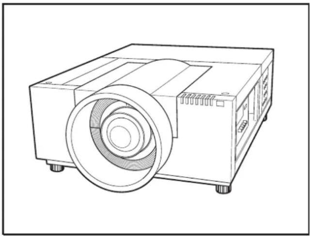
Refer to the Installation procedure corresponding to your projector and install the lens correctly. (See the chart below.)
natural_image
Line drawing of a projector with a circular lens and base mount (no text or symbols)※ For use the other models (other than above cabinet), contact your sales dealer.
Notes on Lens Installation and Replacement

● Lens installation and replacement should be performed by the qualified service personnel.
- It should be followed by this procedure precisely.
- Before attempt to replace the lens, confirm the model number (both the LCD projector and the lens) and use the proper lens.
● The lens cover is on the lens for protection. Be sure to remove the lens cover before installation.
- When installing or removing the lens, be careful not to stain, scratch or damage the lens.
- When shipping the projector with the lens, remove the lens before shipping the projector.
- If you have any questions, contact the dealers.
LIST OF CONTENTS
Following parts are included in the packing.
- LENS 1 pc.
- LENS CAP Front and rear (Each 1 pc.)
- SCREW DRIVER 1 pc.
• INSTALLATION MANUAL 1 pc.

BE SURE TO CHECK FOR SAFETY
After installing or replacing the lens, be sure to check the following for safety.
- Check the lens is securely fixed.
- Check no part is missing, or no mounting part is loose.
Some parts are not used for installation or replacement. Keep these parts for later use.
Note : Figures in this manual may be differ from the actual product.
■ LENS REPLACEMENT AND INSTALLATION PROCEDURE
1 Turn off the projector, press the Main On/Off Switch to Off and unplug the AC power cord from the AC outlet.
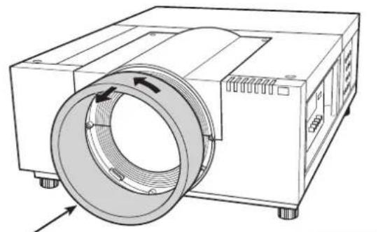
2 Turn the Lens Mount Cover counter-clockwise and take it off by pulling forward. (See Fig. 1)
natural_image
Technical line drawing of a mechanical device with a circular component and directional arrows indicating motion (no text or symbols)Lens Mount Cover
Fig. 1
3 Remove 2 Screws A and loosen 2 Screws B. Slide the Top Cover forward to take off. (See Fig. 2)
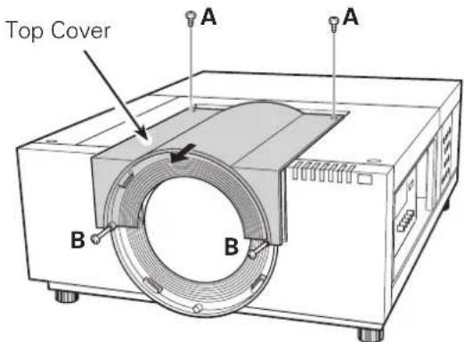
Fig. 2
4 Remove the Cover Plate by lifting upwards. (See Fig. 3)
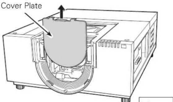
Fig. 3
5 This projector can use three (3) different types of Light-Block Plates, use the Light-Block Plate that corresponds to the appropriate optional lens.
NOTE:
- Make sure the shape of the Light-Block Plate is correct.
- Make sure the mark (UP/DOWN and FRONT/BACK) on Light-Block Plates are correct and set them properly.
- Use the following Light-Block Plate.
Light-Block Plate
Type FK2A
(610 337 0064)
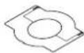
NOTE:
- The Light-Block Plate FK2A is separated to the upper and lower plates.
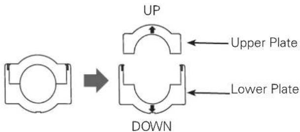
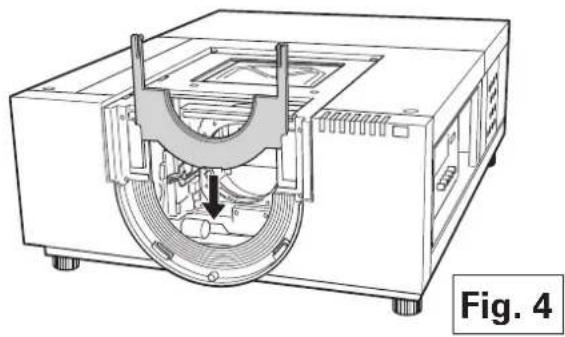
6 Insert the lower Light-Block Plate. (See Fig. 4.)
natural_image
Technical line drawing of a mechanical device with internal components and a downward arrow indicating motion (no text or symbols)
Remove the safety lens cap on the rear of the lens (mounting side). Insert the Lens Attachment and secure with the four (4) screws (supplied). (See Fig. 5.)
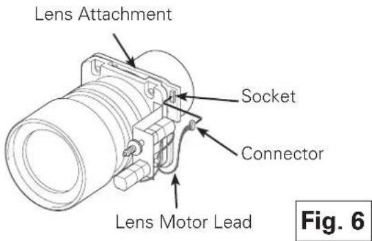
Connect the Lens Motor Lead to the socket on the top loght of the Lens Attachment. (See Fig. 6.)
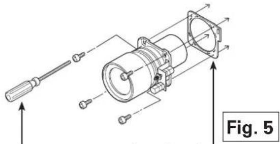
Screw Driver
(supplied with the optional lens)
Part No. (610 275 6029)
Lens Attachment
(supplyed with the projector)
Lens Attachment 01
POA-LNA-01
Part No. (610 303 8742)

Grasp (release lock) the Lens Lock Lever and turn it fully upward. (See Fig. 7)
Install the Lens into the projector. Grasp the Lens Lock Lever and turn the Lever fully downward until lever is Locked (clicked position) properly. (See Fig. 8) After installing the lens, make sure the lens is not loose and properly installed.
LENS LOCK RELEASE
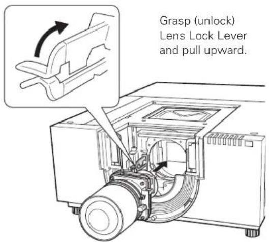
Fig. 7
LENS LOCK
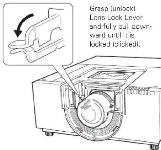
Fig. 8

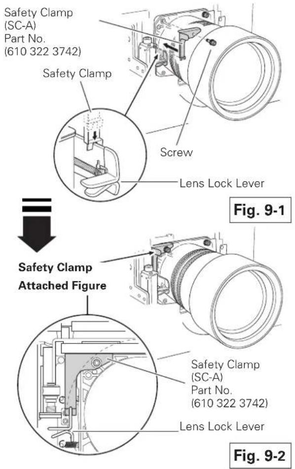
To ensure that the lens is securely fixed to the projector when mounting, be sure to attach the Safety Clamp (supplyed with the projector). There are two different types of Safety Clamps depending on the lens of the projector. Please use Safety Clamp of the SC-A type for this lens.
- Remove the screw holding the lens. (See Fig.9-1)
- Insert the removed screw to the Safety Clamp.
- Place the Safety Clamp in the location of the removed screw. Make sure that the Safety Clamp is mounted to hold the Lens Lock Lever in the lock position. Check the placement of the Safety Clamp. (See Fig. 9-2)

Install the Upper Light-Block Plate into the guide of Lower Light-Block Plate. (See Fig. 10)
Note:
- When installing the Upper Light-Block Plate, the Lower Light-Block Plate should be lifted upward with your hand.
- Hang the ditch on Lower Light-Block Plate to the Upper Light-Block Plate.
- Make sure the mark (UP/DOWN and FRONT/BACK) on Light-Block Plate is correct and set them properly.
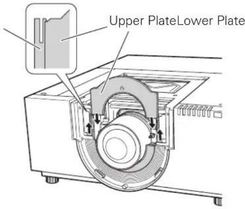
Fig. 10

Replace and fix the Top Cover with two (2) Screws A and 2 screws B. (See Fig. 11)
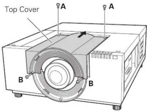
Fig. 11
12
Fit the raised dot of the Lens Mount Cover to the leftmost edge of the Seal on the projector, and then turn the Lens Mount Cover clockwise and adjust the position of the raised dot to the one of the projector. (See Fig. 12)
NOTE:
- If not mounted properly, the Lens Mount Cover may fall, causing hazards of injuly.
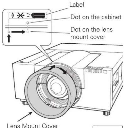
Fig. 12
13
Turn the projector on and operate Lens shift, Zoom and Focus fully to check the Light-Block Plates. If Light-Block Plate interferes with those operations, check the Light-Block Plate is set properly.
FOCUS CORRECTION
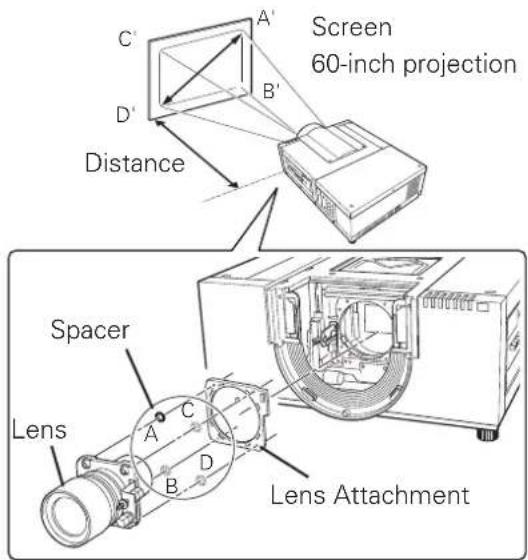
When the lens is attached to the projector and images are being projected onto the screen, the peripheral focus may be out of focus in some localized areas. If this happens, insert the one, of three sizes of spacers, in between the Lens Attachment and the lens to adjust the focus.
Inserting the Spacer corrects the distance on the Lens Adjustment and improves the diagonal focus.
The corrected distance is determined by the thickness of the used spacers. As a guide, the distance is adjusted by approximately 30 mm for each 0.1-mm thickness of the spacers.
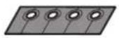
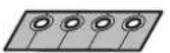
There are three types of spacers supplied with the projector, and there are four of each spacer type. Use these spacers to correct the distance as required.
 | Spacer '1"Color; ClearThickness; 0.1 mm | Correction distance30 mm/for 60-inch projection |
 | Spacer '2"Color; BlackThickness; 0.2 mm | Correction distance60 mm/for 60-inch projection |
 | Spacer '3"Color; CreamThickness; 0.3 mm | Correction distance90 mm/for 60-inch projection |

BE SURE TO CHECK FOR SAFETY
After installing or replacing the lens, be sure to check the following for safety.
- Check the lens is securely fixed.
- Check no part is missing, and no mounting part is loose.
Some parts are not used for installation or replacement. Keep these parts for later use.
Note: Figures in this manual may differ from the actual product.
Brand : SANYO
Model : LNS-S04
Category : Projector accessory