UC-7420 - Thin client Moxa - Free user manual and instructions
Find the device manual for free UC-7420 Moxa in PDF.


| Product Type | RISC-based Universal Communicator / Thin Client |
| CPU | Intel XScale IXP422, 266 MHz |
| RAM | 128 MB SDRAM |
| Flash Memory | 32 MB NOR Flash ROM |
| Serial Ports | 8 RS-232/422/485 (RJ45) |
| Ethernet Ports | 2 x 10/100 Mbps (RJ45) |
| Expansion Slots | PCMCIA Type I/II, CompactFlash Type I/II |
| USB Ports | 2 x USB 2.0 Host, 1 x USB 1.1 Client |
| Display | 128 x 64 dot-matrix LCM with backlight |
| Keypad | 5 buttons |
| Operating System | Embedded Linux (MontaVista 2.4.18) |
| Dimensions (W x H x D) | 197 x 125 x 44 mm |
| Weight | 875 g |
| Power Input | 12 - 48 VDC |
| Power Consumption | 12 W |
| Operating Temperature | -10°C to 60°C (14°F to 140°F) |
| Storage Temperature | -20°C to 80°C (-4°F to 185°F) |
| Humidity | 5% to 95% RH (non-condensing) |
| Cooling | Fanless, robust design |
| Mounting | DIN-rail or wall mounting (brackets included) |
| Regulatory Approvals | FCC Class A, CE Class A, UL, cUL, TÜV |
| Warranty | 5 years |
| Maintenance | No user-serviceable parts. Clean with a dry, soft cloth. Keep away from moisture. |
| Safety Precautions | Mount to a well-grounded surface. Disconnect power before wiring. |
| Spare Parts / Accessories | Power adapter, serial cables (RJ45 to DB9), crossover Ethernet cable, DIN-rail kit, wall-mount kit |
Frequently Asked Questions - UC-7420 Moxa
User questions about UC-7420 Moxa
0 question about this device. Answer the ones you know or ask your own.
Ask a new question about this device
Download the instructions for your Thin client in PDF format for free! Find your manual UC-7420 - Moxa and take your electronic device back in hand. On this page are published all the documents necessary for the use of your device. UC-7420 by Moxa.
USER MANUAL UC-7420 Moxa
Seventh Edition, February 2009
www.moxa.com/product
MOXA®
© 2009 Moxa Inc. All rights reserved. Reproduction without permission is prohibited.
UC-7420/7410 User's Manual
The software described in this manual is furnished under a license agreement and may be used only in accordance with the terms of that agreement.
Copyright Notice
Copyright © 2009 Moxa Inc.
All rights reserved.
Reproduction without permission is prohibited.
Trademarks
MOXA is a registered trademark of Moxa Inc.
All other trademarks or registered marks in this manual belong to their respective manufacturers.
Disclaimer
Information in this document is subject to change without notice and does not represent a commitment on the part of Moxa.
Moxa provides this document “as is,” without warranty of any kind, either expressed or implied, including, but not limited to, its particular purpose. Moxa reserves the right to make improvements and/or changes to this manual, or to the products and/or the programs described in this manual, at any time.
Information provided in this manual is intended to be accurate and reliable. However, Moxa assumes no responsibility for its use, or for any infringements on the rights of third parties that may result from its use.
This product might include unintentional technical or typographical errors. Changes are periodically made to the information herein to correct such errors, and these changes are incorporated into new editions of the publication.
Technical Support Contact Information www.moxa.com/support
Moxa Americas:
Toll-free: 1-888-669-2872
Tel: +1-714-528-6777
Fax: +1-714-528-6778
Moxa China (Shanghai office):
Toll-free: 800-820-5036
Tel: +86-21-5258-9955
Fax: +86-10-6872-3958
Moxa Europe:
Tel: +49-89-3 70 03 99-0
Fax: +49-89-3 70 03 99-99
Moxa Asia-Pacific:
Chapter 1 Introduction....1-1
Overview....1-2
Package Checklist.... 1-2
Product Features....1-3
Product Hardware Specifications 1-3
Hardware Introduction.... 1-4
Appearance and Dimensions 1-4
Hardware Block Diagram.... 1-6
LED Indicators 1-6
Reset-type Buttons 1-7
Real Time Clock.... 1-7
Placement Options 1-8
Wall or Cabinet 1-8
DIN-Rail Mounting 1-9
Hardware Connection Description.... 1-9
Wiring Requirements 1-9
Connecting the Power 1-10
Grounding UC-7420/7410 1-10
Connecting to the Network.... 1-11
Connecting to a Serial Device 1-11
Connecting to the Console Port.... 1-11
PCMCIA....1-11
CompactFlash....1-12
Software Introduction 1-12
Software Architecture.... 1-12
Journaling Flash File System (JFFS2)....1-13
Software Package 1-14
Chapter 2 Getting Started....2-1
Powering on UC-7420/7410 2-2
Connecting UC-7420/7410 to a PC 2-2
Serial Console 2-2
Telnet Console....2-3
SSH Console 2-4
Configuring the Ethernet Interface 2-5
Modifying Network Settings with the Serial Console 2-5
Modifying Network Settings over the Network 2-7
Configuring the WLAN via the PCMCIA Interface 2-7
IEEE802.11b 2-7
IEEE802.11g 2-9
Test Program—Developing Hello.c....2-13
Installing the Tool Chain (Linux).... 2-13
Checking the Flash Memory Space.... 2-13
Compiling Hello.c 2-14
Uploading "Hello" to UC-7420/7410 and Running the Program.... 2-15
Developing Your First Application 2-15
Testing Environment 2-15
Compiling tcps2.c.... 2-16
Uploading tcp2-release and Running the Program 2-17
Testing Procedure Summary 2-19
Chapter 3 Managing Embedded Linux ....3-1
System Version Information.... 3-2
System Image Backup.... 3-2
Upgrading the Firmware.... 3-2
Loading Factory Defaults....3-5
Enabling and Disabling Daemons....3-5
Setting the Run-Level 3-8
Adjusting the System Time....3-9
Setting the Time Manually 3-9
NTP Client.... 3-10
Updating the Time Automatically 3-10
Cron—daemon to Execute Scheduled Commands ....3-11
Connecting Peripherals.... 3-12
USB Mass Storage....3-12
CF Mass Storage 3-12
Chapter 4 Managing Communications....4-1
Telnet / FTP 4-2
DNS 4-2
Web Service—Apache 4-3
Saving a Web Page to the CF Card 4-5
IPTABLES 4-6
NAT 4-10
NAT Example 4-10
Enabling NAT at Bootup....4-11
Dial-up Service—PPP....4-11
PPPoE....4-15
NFS (Network File System) 4-18
Setting up UC-7420/7410 as an NFS Server 4-18
Setting up UC-7420/7410 as an NFS Client.... 4-19
Mail....4-19
SNMP 4-20
Open VPN 4-21
Chapter 5 Programmer's Guide....5-1
Flash Memory Map....5-2
Linux Tool Chain Introduction....5-2
Debugging with GDB 5-4
Device API....5-4
RTC (Real Time Clock) 5-4
Buzzer 5-5
WDT (Watch Dog Timer) 5-5
UART 5-9
LCM....5-10
KeyPad....5-11
Make File Example....5-11
Appendix A System Commands....A-1
Linux normal command utility collection.... A-1
File manager....A-1
Editor....A-1
Network....A-1
Process.... A-2
Other....A-2
Moxa special utilities....A-2
Welcome to Moxa UC-7420/7410 RISC-based Communication Platforms. Available features include eight RS-232/422/485 serial ports, dual 10/100 Mbps Ethernet ports, a PCMCIA interface for wireless LAN communication, and CompactFlash and USB ports for mass storage disk expansion, making UC-7420/7410 ideal for your embedded applications.
The following topics are covered in this chapter:
Overview
Package Checklist
Product Features
Product Hardware Specifications
Hardware Introduction
➢ Appearance and Dimensions
Hardware Block Diagram
LED Indicators
Reset-type Buttons
Real Time Clock
□ Placement Options
➢ Wall or Cabinet
▶ DIN-Rail Mounting
□ Hardware Connection Description
Wiring Requirements
Connecting the Power
➢ Grounding UC-7420/7410
Connecting to the Network
Connecting to a Serial Device
Connecting to the Console Port
PCMCIA
CompactFlash
□ Software Introduction
Software Architecture
▶ Journaling Flash File System (JFFS2)
Software Package
Software Version Comparison Table
Overview
UC-7420/7410 RISC-based Communication Platforms are ideal for embedded applications. UC-7420/7410 has eight RS-232/422/485 serial ports, dual 10/100 Mbps Ethernet ports, a PCMCIA interface for wireless LAN communication, and CompactFlash and USB port for mass storage flash disk expansion.
UC-7420/7410 uses an Intel XScale IXP422 266 Mhz RISC CPU. Unlike the X86 CPU, which uses a CISC design, the IXP422's RISC design architecture and modern semiconductor technology provide UC-7420/7410 with a powerful computing engine and communication functions, but without generating a lot of heat. The built-in 32 MB NOR Flash ROM and 128 MB SDRAM give you enough memory to put your application software directly on UC-7420/7410. And since the dual LAN ports are built right into the IXP-422 CPU, UC-7420/7410 makes an ideal communication platform for Network Security applications. If your application requires placing UC-7420/7410 in a location that is not located near an Ethernet LAN connection, you can use UC-7420/7410's PCMCIA port to attach a wireless LAN card.
The pre-installed Linux operating system provides an open software operating system for your software program development. Software written for desktop PCs can be easily ported to the UC-7420/7410 platform with a GNU cross compiler, without needing to modify the source code. All of the necessary device drivers, such as a PCMCIA Wireless LAN module and Keypad, LCM, and Buzzer control, are also included with UC-7420/7410. The Operating System, device drivers, and the software you develop for your own application, can all be stored in UC-7420/7410's Flash memory.
Package Checklist
UC-7410-LX
RISC-based Universal Communicator with 8 Serial Ports, Dual Ethernet, Linux OS.
UC-7420-LX
RISC-based Universal Communicator with 8 Serial Ports, Dual Ethernet, PCMCIA, Compact Flash, USB, Linux OS.
UC-7420/7410 is shipped with the following items:
• UC-7410 or UC-7420
- Wall-Mounting Kit
• DIN-Rail Mounting Kit
• UC-7420/7410 Quick Installation Guide
• UC-7420/7410 Documentation & Software CD
• Cross-over Ethernet cable
• CBL-RJ45M9-150: 150 cm, 8-pin RJ45 to Male DB9 serial port cable
• CBL-RJ45F9-150: 150 cm, 8-pin RJ45 to Female DB9 console port cable
- Power Adaptor
• Product Warranty Booklet
NOTE: Notify your sales representative if any of the above items is missing or damaged.
Product Features
• Intel XScale IXP422 266 MHz Processor
• On-board 128 MB RAM, 32 MB Flash ROM
• Eight RS-232/422/485 serial ports
• Dual 10/100 Mbps Ethernet
• PCMCIA/CompactFlash expansion (UC-7420 only)
• USB Host for mass storage device (UC-7420 only)
• LCM display and Keypad for HMI
• Linux-ready communication platform
• DIN-Rail or wall mounting installation
- Robust fanless design
Product Hardware Specifications
| UC-7410-LX | UC7420-LX | |
| CPU | Intel XScale IXP422, 266 MHz | |
| RAM | 128 MB | |
| Flash | 32 MB | |
| LAN | Auto-sensing 10/100 Mbps x 2 | |
| LAN Protection | Built-in 1.5 KV magnetic isolation | |
| Serial Ports | Eight RS-232/422/485 ports | |
| RS-232 signals: TxD, RxD, DTR, DSR, RTS, CTS, DCD, GND | ||
| RS-422 signals: TxD+, TxD-, RxD+, RxD-, GND | ||
| 4 wire RS-485 signals: TxD+, TxD-, RxD+, RxD-, GND | ||
| 2 wire RS-485 signals: Data+, Data-, GND | ||
| Serial Protection | 15 KV ESD for all signals | |
| Data bits | 5, 6, 7, 8 | |
| Stop bits | 1, 1.5, 2 | |
| Parity | None, even, odd, space, mark | |
| Flow Control | RTS/CTS, XON/XOFF | |
| Speed | 50 bps to 921.6 Kbps (50 bps to 230.4 Kbps for Hardware version V1.0) | |
| Serial Console/PPP | RS-232 x 1, RJ45 | |
| USB 2.0 Host | N/A | 2 |
| USB 1.1 Client | 1 | 1 |
| PCMCIA | N/A | PCMCIA type I/II socket x 1 |
| Compact Flash | N/A | CompactFlash type I/II socket x 1 |
| Real Time Clock | Yes | |
| LCM | 128 x 64 dots | |
| Buzzer | Yes | |
| LEDs | Serial x 8, Console/PPP x 1, PWR x 1, Ready x 1, LAN 10/100 x 2 | |
| Key Pad | 5 buttons | |
| Power input | 12-48 VDC | |
| Power Consumption | 10W | 12W |
| Dimensions | 197 x 125 x 44mm | |
| Gross Weight | 875 g | |
| Operating temperature | -10 to 60°C, (14 to 140°F), 5 to 95% RH | |
| Storage temperature | -20 to 80°C, (-4 to 185°F), 5 to 95% RH | |
| Regulatory Approvals | EMC: FCC Class A, CE Class ASafety: UL, CUL, TÜV | |
| Warranty | 5 years | |
Hardware Introduction
Appearance and Dimensions
Appearance
UC-7410/7420 Rear View
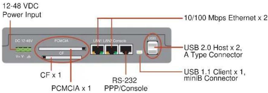
UC-7410/7420 Top View
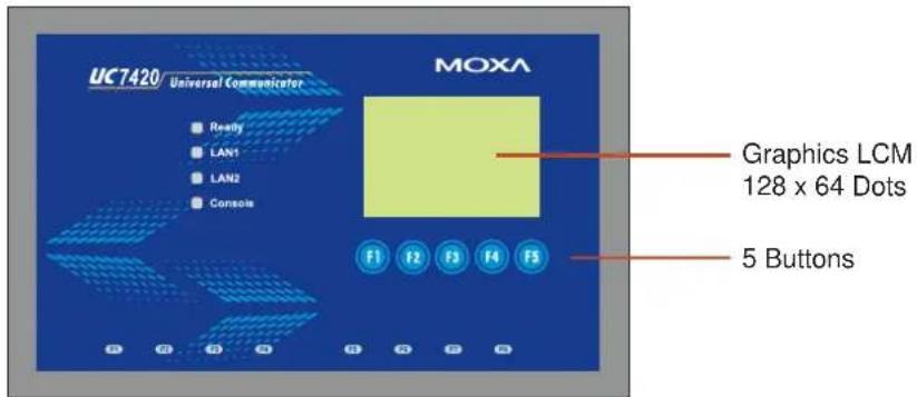
UC-7410/7420 Front View
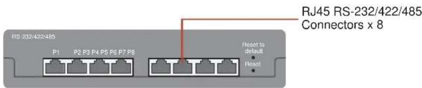
Dimensions
![Ready LAN1 LAN2 Console F1 F2 F3 F4 F5 P0 P2 P3 P4 P5 P6 P7 P8 125 mm [4.92" 44 mm [1.73" 197 mm [7.76"]](/content/2026/06/1146084/images/b2bfda865140507328c3d22cb00e52ae660e0dd235785605376192ae48050ef6.jpg)
Hardware Block Diagram
The following block diagram shows the layout of UC-7420's internal components (the layout for UC-7410 is slightly different).
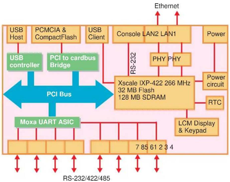
flowchart
graph TD
    A["USB Host"] --> B["USB controller"]
    C["PCMCIA & CompactFlash"] --> D["PCI to cardbus Bridge"]
    E["USB Client"] --> F["Console LAN2 LAN1"]
    G["Power"] --> H["Power circuit"]
    I["Xscale IXP-422 266 MHz 32 MB Flash 128 MB SDRAM"] --> J["PHY PHY"]
    K["Moxa UART ASIC"] --> L["7 85 61 2 3 4"]
    M["LCM Display & Keypad"] --> N["RTC"]
    O["RS-232/422/485"] --> P["RS-232"]
    Q["Ethernet"] --> R["Internet"]
    style A fill:#f9f,stroke:#333
    style C fill:#f9f,stroke:#333
    style E fill:#f9f,stroke:#333
    style G fill:#f9f,stroke:#333
    style I fill:#f9f,stroke:#333
    style M fill:#f9f,stroke:#333
    style O fill:#f9f,stroke:#333
    style Q fill:#f9f,stroke:#333
    style Q fill:#ccf,stroke:#333
LED Indicators
UC-7420/7410 has 12 LED indicators on the top panel. Refer to the following table for information about each LED.
| LED Name Color Meaning | |
| Ready Green Power is ON, and system is ready (after booting up) | |
| LAN1, LAN2 | Yellow 10 Mbps Ethernet connection |
| Green 100 Mbps Ethernet connection | |
| Console | Yellow Console port is receiving RX data from the serial device. |
| Green Console port is transmitting TX data to the serial device. | |
| P5, P6, P7, P8 | Yellow Serial port is receiving RX data from the serial device. P1, P2, P3, P4, |
| Green Serial port is transmitting TX data to the serial device. | |
Reset-type Buttons
UC-7420/7410 has two reset-type buttons. The button labeled Reset has the same effect as unplugging the power and then plugging the power back in. The button labeled Reset to default returns UC-7420/7410 to the factory default parameter configuration.
Reset Button
Pressing the Reset button initiates a hardware reboot. The button plays the same role as a desktop PC's reset button.
In normal use, you should NOT use the Reset Button. You should only use this function if the software is not working properly. To reset an embedded linux system, always use the software reboot command />reboot to protect the integrity of data being transmitted or processed.
Reset to default Button
Press the Reset to default button continuously for at least 5 seconds to load the factory default configuration. After the factory default configuration has been loaded, the system will reboot automatically. The Ready LED will blink on and off for the first 5 seconds, and then maintain a steady glow once the system has rebooted.
We recommend that you only use this function if the software is not working properly and you want to load factory default settings. To reset an embedded linux system, always use the software reboot command />reboot to protect the integrity of data being transmitted or processed. The Reset to default button is not designed to hard reboot UC-7420/7410.

ATTENTION
Reset to default preserves user's data
The Reset to default button will NOT format the user directory and erase the user's data. Pressing the Reset to default button will only load the configuration file. All files in the /etc directory will revert to their factory defaults, but other User Data will still exist in the Flash ROM.
If you need to load the default System Image file, refer to the “System Image Backup” section in Chapter 3,
"Reset to Default" supported by hardware versions V1.2 and higher
The Reset to default button is only supported after hardware version V1.2. You can identify the hardware version from UC-7420/7410's bottom label. You will need to contact Moxa to determine the version of your product's hardware. When contacting our customer support team, you will need to provide the product's Serial Number (S/N), which can be found on UC-7420/7410's bottom label.
Real Time Clock
UC-7420/7410's real time clock is powered by a lithium battery. We strongly recommend that you do not replace the lithium battery without help from a qualified Moxa support engineer. If you need to change the battery, contact Moxa RMA service team.

WARNING
There is a risk of explosion if the battery is replaced by an incorrect type.
Placement Options
Wall or Cabinet
The two metal brackets that come standard with UC-7420/7410 are used to attach UC-7420/7410 to a wall, or the inside of a cabinet. Use two screws per bracket first to attach the brackets to the bottom of the UC-7420/7410 (Fig. A). Next, use two screws per bracket to attach the UC-7420/7410 to a wall or cabinet (Fig. B).
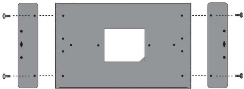
natural_image
Pure mechanical assembly diagram showing two rectangular components with mounting holes and a central square component (no text or symbols)Figure A: UC-7420/7410 Universal Communicator Wall Mounting Brackets (bottom view)
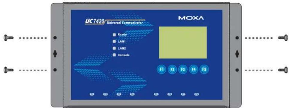
Figure B: UC-7420/7410 Universal Communicator—Wall Mounting Brackets (top view)
DIN-Rail Mounting
The aluminum DIN-Rail attachment plate is included in the package. If you need to reattach the DIN-Rail attachment plate to UC-7420/7410, make sure the stiff metal spring is situated towards the top, as shown in the figures below.
- Insert the top of the DIN-Rail into the slot just below the stiff metal spring.
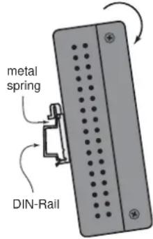
- The DIN-Rail attachment unit will snap into place as shown below.
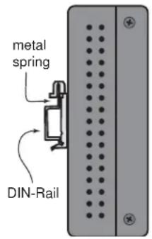
To remove UC-7420/7410 from the DIN-Rail, simply reverse Steps 1 and 2 above.
Hardware Connection Description
This section describes how to connect UC-7420/7410 to serial devices for first time testing purposes. We cover Wiring Requirements, Connecting the Power, Grounding UC-7420/7410, Connecting to the Network, Connecting to a Serial Device, Connecting to the Console Port, PCMCIA, and CompactFlash.
Wiring Requirements

ATTENTION
Safety First!
Be sure to disconnect the power cord before installing and/or wiring your UC-7420/7410.
Wiring Caution!
Calculate the maximum possible current in each power wire and common wire. Observe all electrical codes dictating the maximum current allowable for each wire size.
If the current goes above the maximum ratings, the wiring could overheat, causing serious damage to your equipment.
Temperature Caution!
Be careful when handling UC-7420/7410. When plugged in, UC-7420/7410's internal components generate heat, and consequently the outer casing may feel hot to the touch.
You should also observe the following common wiring rules:
- Use separate paths to route wiring for power and devices. If power wiring and device wiring paths must cross, make sure the wires are perpendicular at the intersection point.
NOTE: Do not run signal or communication wiring and power wiring in the same wire conduit. To avoid interference, wires with different signal characteristics should be routed separately.
- You can use the type of signal transmitted through a wire to determine which wires should be kept separate. The rule of thumb is that wiring that shares similar electrical characteristics can be bundled together.
- Keep input wiring and output wiring separate.
- Where necessary, it is strongly advised that you label wiring to all devices in the system.
Connecting the Power
Connect the 12-48 VDC power line with UC-7420/7410's terminal block. If the power is properly supplied, the Ready LED will illuminate with a solid green color after 30 to 60 seconds have passed.
Grounding UC-7420/7410
Grounding and wire routing helps limit the effects of noise due to electromagnetic interference (EMI). Run the ground connection from the ground screw to the grounding surface prior to connecting devices.

ATTENTION
This product is intended to be mounted to a well-grounded mounting surface, such as a metal panel.
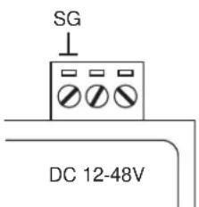
SG: The Shielded Ground (sometimes called Protected Ground) contact is the left most contact of the 3-pin power terminal block connector when viewed from the angle shown here. Connect the SG wire to an appropriate grounded metal surface.
Connecting to the Network
Connect one end of the Ethernet cable to one of UC-7420/7410's 10/100M Ethernet ports (8-pin RJ45) and the other end of the cable to the Ethernet network. If the cable is properly connected, UC-7420/7410 will indicate a valid connection to the Ethernet in the following ways:
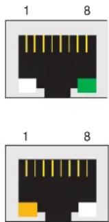
The bottom right corner LED indicator maintains a solid green color when the cable is properly connected to a 100 Mbps Ethernet network. The LED will flash on and off when Ethernet packets are being transmitted or received. The bottom left corner LED indicator maintains a solid orange color when the cable is properly connected to a 10 Mbps Ethernet network. The LED will flash on and off when Ethernet packets are being transmitted or received.
| Pin Signal | |
| 1 | ETx+ |
| 2 | ETx- |
| 3 | ERx+ |
| 4 | --- |
| 5 | --- |
| 6 | ERx- |
| 7 | --- |
| 8 | --- |
Connecting to a Serial Device
Use properly wired serial cables to connect UC-7420/7410 to serial devices. UC-7420/7410's serial ports (P1 to P8) use 8-pin RJ45 connectors. The ports can be configured by software for RS-232, RS-422, or 2-wire RS-485. The precise pin assignments are shown in the following table:
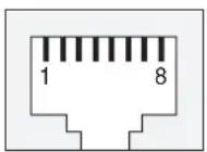
| Pin | RS-232 | RS-422 | RS-485 | |
| 1 | DSR | --- | --- | |
| 2 | RTS | TXD+ | --- | |
| 3 | GND | GND | GND | |
| 4 | TXD | TXD- | --- | |
| 5 | RXD | RXD+ | Data+ | |
| 6 | DCD | RXD- | Data- | |
| 7 | CTS | --- | --- | |
| 8 | DTR | --- | --- | |
Connecting to the Console Port
UC-7420/7410's console port is an 8-pin RJ45 RS-232 port. The port can be used to connect to the console utility from a remote console via a V90 or GPRS modem with PPP protocol. The pin definition is the same as for the serial ports (P1 to P8). For normal data acquisition applications, you should connect to UC-7420/7410's serial ports (P1 to P8) via a V90 or GPRS modem. If you would like to use the console port for normal data acquisition applications, you can set the Console port to startup via PPP protocol. For details, refer to "Dial-up Service—PPP" section in Chapter 4.
PCMCIA
The PCMCIA slot supports the CardBus (Card-32) Card standard and 16-bit (PCMCIA 2.1/JEIDA 4.2) Card standard. It supports +3.3V, +5V, and +12V at a working voltage of 120 mA. Wireless LAN card expansion is optional. The Wireless LAN card provided by Moxa lets you connect UC-7420/7410 to a Wireless LAN, with both 802.1b and 802.11g interfaces supported.
If you need device drivers for other kinds of PCMCIA cards, contact Moxa for information on how to initiate a cooperative development project.
CompactFlash
UC-7420 provides one CompactFlash slot that supports CompactFlash type I/II card expansion. Currently, Moxa provides a CompactFlash disk for plug & play mass storage expansion. You may also use flash disks available from most computer supply outlets. The CompactFlash will be mounted at /mnt/hda
If you need device drivers for other kinds of mass storage cards, contact Moxa for information on how to initiate a cooperative development project.
Software Introduction
Software Architecture
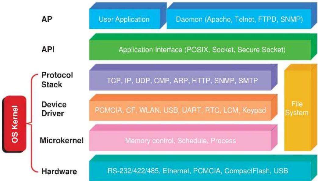
The Linux operating system that is pre-installed in UC-7420/7410 follows the standard Linux architecture, making it easy to port programs that follow the POSIX standard to UC-7420/7410. Porting is done with the GNU Tool Chain provided by Moxa. In addition to the Standard POSIX API, device drivers for the LCM, buzzer and Keypad controls, USB/CompactFlash mass storage, UART, and Wireless LAN PCMCIA card are also included in the UC-7420/7410 Linux system.
flowchart
graph TD
    A["Hardware"] --> B["Microkernel"]
    B --> C["Device Driver"]
    C --> D["Protocol Stack"]
    D --> E["API"]
    E --> F["AP"]

    subgraph OS_Kernel
        G["OS Kernel"]
        H["Hardware"]
        I["Device Driver"]
        J["Protocol Stack"]
        K["Microkernel"]
        L["API"]
        M["AP"]
    end

    N["RS-232/422/485, Ethernet, PCMCIA, CompactFlash, USB"]
    O["File System"]
    P["User Application"] --> Q["Daemon (Apache, Telnet, FTPD, SNMP)"]
    R["TCP, IP, UDP, CMP, ARP, HTTP, SNMP, SMTP"]
    S["PCMCIA, CF, WLAN, USB, UART, RTC, LCM, Keypad"]
    T["Memory control, Schedule, Process"]
UC-7420/7410's Flash ROM is partitioned into Boot Loader, Linux Kernel, Mini Root File System, and User Root File System partitions.
In order to prevent user applications from crashing the Root File System, UC-7420/7410 uses a specially designed Mini File System with Protected Configuration for emergency use. This Mini File System comes with serial and Ethernet communication capability for users to load the Factory Default Image file. The Mini File System will only be activated if the boot loader fails to load the User Root File System.
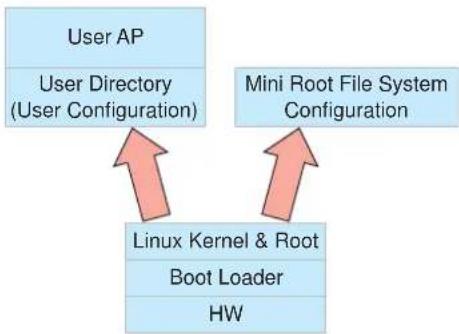
flowchart
graph TD
    A["User AP\nUser Directory\n(User Configuration)"] --> B["Linux Kernel & Root\nBoot Loader\nHW"]
    C["Mini Root File System\nConfiguration"] --> B
To improve system reliability, UC-7420/7410 has a built-in mechanism that prevents the system from crashing. The procedure is as follows.
When the Linux kernel boots up, the kernel will mount the root file system, and then enable services and daemons. During this time, the kernel will start searching for system configuration parameters via rc or inittab.
Normally, the kernel uses the User Root File System to boot up the system. The Mini Root File System is protected, and cannot be changed by the user, providing a "safe" zone. The kernel will only use the Mini Root File System when the User Root File System crashes.
For more information about the memory map and programming, refer to Chapter 5, "Programmer's Guide."
Journaling Flash File System (JFFS2)
The User Root File System in the flash memory is formatted with the Journaling Flash File System (JFFS2). The formatting process places a compressed file system in the flash memory, transparent to the user.
The Journaling Flash File System (JFFS2), which was developed by Axis Communications in Sweden, puts a file system directly on the flash, instead of emulating a block device. It is designed for use on flash-ROM chips and recognizes the special write requirements of a flash-ROM chip. JFFS2 implements wear-leveling to extend the life of the flash disk, and stores the flash directory structure in the RAM. A log-structured file system is maintained at all times. The system is always consistent, even if it encounters crashes or improper power-downs, and does not require fsck (file system check) on boot-up.
JFFS2 is the newest version of JFFS. It provides improved wear-leveling and garbage-collection performance; improved RAM footprint and response to system-memory pressure, improved concurrency and support for suspending flash erases; marking of bad sectors with continued use of the remaining good sectors, which enhances the write-life of the devices; native data compression inside the file system design; support for hard links.
The key features of JFFS2 are:
• Targets the Flash ROM Directly
- Robustness
• Consistency across power failures
- No integrity scan (fsck) is required at boot time after normal or abnormal shutdown
• Explicit wear leveling
• Transparent compression
Although JFFS2 is a journaling file system, this does not preclude the loss of data. The file system will remain in a consistent state across power failures and will always be mountable. However, if the board is powered down during a write then the incomplete write will be rolled back on the next boot, but writes that have already been completed will not be affected.
Additional information about JFFS2 is available at:
http://sources.redhat.com/jffs2/jffs2.pdf
http://developer.axis.com/software/jffs/
http://www.linux-mtd.infradead.org/
Software Package
| Boot Loader | Redboot (V1.92) |
| Kernel | MontaVista embedded Linux 2.4.18 |
| Protocol Stack | ARP, PPP, CHAP, PAP, IPv4, ICMP, TCP, UDP, DHCP, FTP, SNMP V1, HTTP, NTP, NFS, SMTP, SSH 1.0/2.0, SSL, Telnet, PPPoE, OpenVPN |
| File System | JFFS2, NFS, Ext2, Ext3, VFAT/FAT |
| OS shell command | bash |
| Busybox | Linux normal command utility collection |
| Utilities | |
| tinylogin | login and user manager utility |
| telnet telnet client program | |
| ftp FTP client program | |
| smtpclient email utility | |
| scp | Secure file transfer Client Program |
| Daemons | |
| pppd | dial in/out over serial port daemon |
| snmpd snmpd agent | daemon |
| telnetd | telnet server daemon |
| inetd TCP server manager program | |
| ftpd | ftp server daemon |
| apache | web server daemon |
| sshd secure shell server | |
| nfs-user-server network file system server | |
| openvpn | virtual private network |
| openssl | open SSL |
| Linux Tool Chain | |
| Gcc (V3.3.2) | C/C++ PC Cross Compiler |
| GDB (V5.3) | Source Level Debug Server |
| Glibc (V2.2.5) | POSIX standard C library |
In this chapter, we explain how to connect UC-7420/7410, turn on the power, and then get started using the programming and other functions.
The following topics are covered in this chapter:
□ Powering on UC-7420/7410
☐ Connecting UC-7420/7410 to a PC
Serial Console
Telnet Console
▶ SSH Console
☐ Configuring the Ethernet Interface
➢ Modifying Network Settings with the Serial Console
➢ Modifying Network Settings over the Network
☐ Configuring the WLAN via the PCMCIA Interface
IEEE802.11b
IEEE802.11g
☐ Test Program—Developing Hello.c
Installing the Tool Chain (Linux)
➢ Checking the Flash Memory Space
▶ Compiling Hello.c
- Uploading “Hello” to UC-7420/7410 and Running the Program
☐ Developing Your First Application
Testing Environment
▶ Compiling tcps2.c
- Uploading tcp2-release and Running the Program
➢ Testing Procedure Summary
Powering on UC-7420/7410
Connect the SG wire to the Shielded Contact located in the upper left corner of the UC-7420/7410, and then power on UC-7420/7410 by connecting it to the power adaptor. It takes about 30 to 60 seconds for the system to boot up. Once the system is ready, the Ready LED will light up, and the Network address settings will appear on the LCM display.
NOTE
After connecting UC-7420/7410 to the power supply, it will take about 30 to 60 seconds for the operating system to boot up. The green Ready LED will not turn on until the operating system is ready.
Connecting UC-7420/7410 to a PC
There are two ways to connect UC-7420/7410 to a PC: through the serial Console port or via Telnet over the network.
Serial Console
The serial console port gives users a convenient way of connecting to UC-7420/7410's console utility. This method is particularly useful when using UC-7420/7410 for the first time. The signal is transmitted over a direct serial connection, so you do not need to know either of UC-7420/7410's two IP addresses in order to connect to the serial console utility.
Use the serial console port settings shown below.
| Baud rate | 115200 bps |
| Parity | None |
| Data bits | 8 |
| Stop bits: | 1 |
| Flow Control | None |
| Terminal | VT100 |
Once the connection is established, the following window will open.
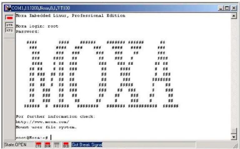
To log in, type the Login name and password as requested. The default values are both root:
Login: root
Password: root
Telnet Console
If you know at least one of the two IP addresses and netmasks, then you can use Telnet to connect to UC-7420/7410's console utility. The default IP address and Netmask for each of the two ports are given below:
| Default IP Address Netmask | ||
| LAN 1 | 192.168.3.127 | 255.255.255.0 |
| LAN 2 | 192.168.4.127 | 255.255.255.0 |
Use a cross-over Ethernet cable to connect directly from your PC to UC-7420/7410. You should first modify your PC's IP address and netmask so that your PC is on the same subnet as one of UC-7420/7410's two LAN ports. For example, if you connect to LAN 1, you can set your PC's IP address to 192.168.3.126 and netmask to 255.255.255.0. If you connect to LAN 2, you can set your PC's IP address to 192.168.4.126 and netmask to 255.255.255.0.
To connect to a hub or switch connected to your local LAN, use a straight-through Ethernet cable. The default IP addresses and netmasks are shown above. To login, type the Login name and password as requested. The default values are both root:
Login: root
Password: root
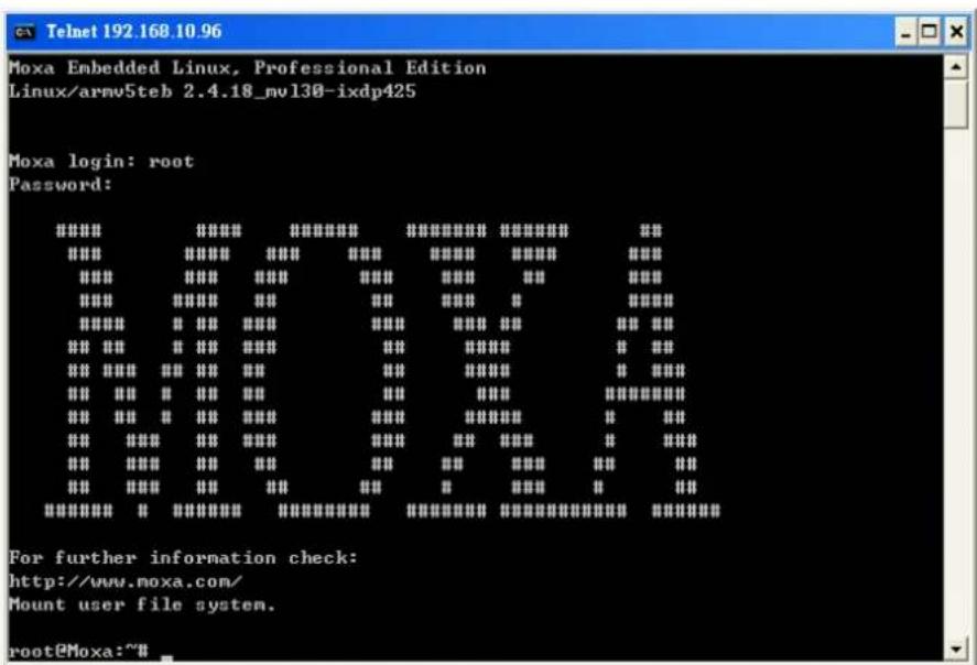
You can proceed with the configuration of UC-7420/7410's network settings when you reach the bash command shell. Configuration instructions are given in the next section.

ATTENTION
Serial Console Reminder
Remember to choose VT100 as the terminal type. Use cable CBL-RJ45F9-150, which comes with UC-7420/7410, to connect to the serial console port.
Telnet Reminder
When connecting to UC-7420/7410 over a LAN, you must configure your PC's Ethernet IP address to be on the same subnet as the UC-7420/7410 you wish to contact. If you do not get connected on the first try, re-check the serial and IP settings, and then unplug and re-plug UC-7420/7410's power cord.
SSH Console
UC-7420/7410 supports an SSH Console to offer users with better security options.
Windows Users
Click on the link http://www.chiark.greenend.org.uk/\~sgtatham/putty/download.html to download PuTTY (free software) to set up an SSH console for UC-7420/7410 in a Windows environment. The following figure shows a simple example of the configuration that is required.
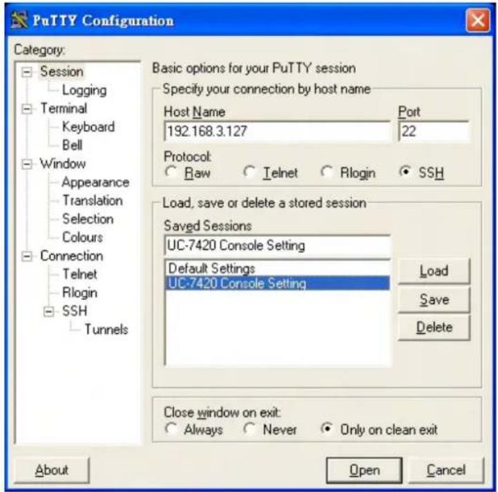
Linux Users
From a Linux machine, use the "ssh" command to access UC-7420/7410's Console utility via SSH.
ssh 192.168.3.127
Select yes to complete the connection.
[root@bee_notebook root]# ssh 192.168.3.127
The authenticity of host '192.168.3.127 (192.168.3.127)' can't be established.
RSA key fingerprint is 8b:ee:ff:84:41:25:fc:cd:2a:f2:92:8f:cb:lf:6b:2f.
Are you sure you want to continue connection (yes/no)? yes_
NOTE
SSH provides better security compared to Telnet for accessing UC-7420/7410's Console utility over the network.
Configuring the Ethernet Interface
UC-7420/7410's network settings can be modified with the serial Console, or online over the network.
Modifying Network Settings with the Serial Console
In this section, we use the serial console to modify UC-7420/7410's network settings.
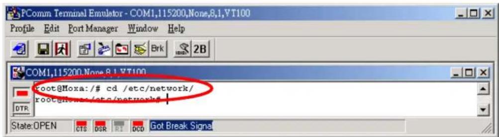
- Follow the instructions given in a previous section to access UC-7420/7410's Console Utility via the serial Console port, and then type #cd /etc/network to change directories.
- Type #vi interfaces to edit the network configuration file with vi editor. You can configure UC-7420/7410's Ethernet ports for static or dynamic (DHCP) IP addresses.
Static IP addresses:
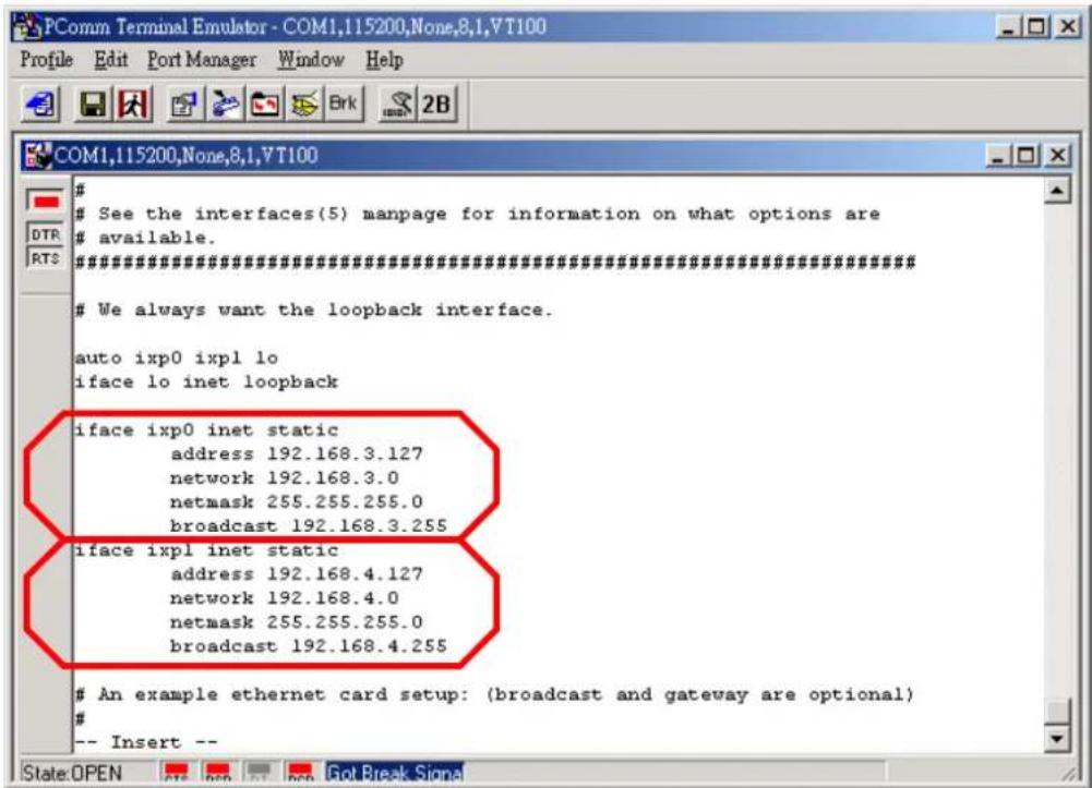
As shown below, 4 network addresses need to be modified: address, network, netmask, and broadcast. The default IP addresses are 192.168.3.127 for LAN1 and 192.168.4.127 for LAN2, with default netmask of 255.255.255.0.
Dynamic IP addresses:
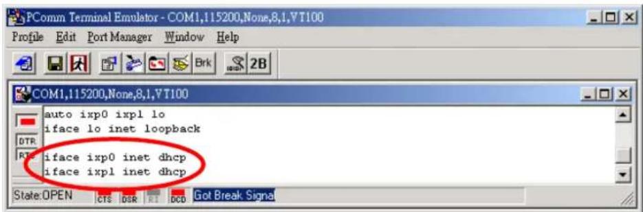
By default, UC-7420/7410 is configured for "static" IP addresses. To configure one or both LAN ports to request an IP address dynamically, replace static with dhcp and then delete the address, network, netmask, and broadcast lines.
| Default Setting for LAN1 Dynamic Setting using DHCP | |
| iface ixp0 inetstaticaddress 192.168.3.127network: 192.168.3.0netmask 255.255.255.0broadcast 192.168.3.255 | iface ixp0 inet dhcp |
- After the boot settings of the LAN interface have been modified, issue the following command to activate the LAN settings immediately:
/etc/init.d/networking restart
NOTE
After changing the IP settings, use the networking restart command to activate the new IP address. However, the LCM display will still show the old IP address. To update the LCM display, you will need to reboot the UC-7420/7410.
Modifying Network Settings over the Network
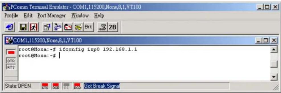
IP settings can be activated over the network, but the new settings will not be saved to the flash ROM without modifying the file /etc/network/interfaces.
For example, type the command #ifconfig ixp0 192.168.1.1 to change the IP address of LAN1 to 192.168.1.1.
Configuring the WLAN via the PCMCIA Interface
IEEE802.11b
The following IEEE802.11b wireless modules are supported:
- NDC NWH1010
- Senao NL-2511CD PLUS(F200)
• Senao NL-2511CD PLUS EXT2 MERCURY (ETSI)
• Senao NI3-2511CD-PLUS3
• DARK DKW11-330HP - DARK XI-330H
• Planex (PCI) GW-NS11H - Corega CG-WLPCCL-11
To configure the WLAN for IEEE802.11b:
- Unplug the PCMCIA Wireless LAN card first.
- Configure the Wireless LAN card's default IP setting profile.
(Default IP address is 192.168.5.127, netmask 255.255.255.0)
Edit network.opts with the following command to edit Wireless LAN's default setting.
vi /etc/pcmcia/network.opts
![Use DHCP (via /sbin/dhcpcd, /sbin/dhclient, or /sbin/pump)? [y/n] DHCP="n" If you need to explicitly specify a hostname for DHCP requests DHCP_HCSTNAME="" Web's IF address, netmask, network address, broadcast address IFADDR="192.168.5.127" NETMASK="255.255.255.0" arport.opts wireless NETMCRR="192.168.5.0" BROADCAST="192.168.5.cbb" serial.opts wlan-ng Gateway address for static routing wlan-ng.conf #GATEWAY="10.0.1.1" /etc/pcmcia/network.opts "/etc/pcmcia/network.opts" line 1 of 48 --2%--](/content/2026/06/1146084/images/e436b64b31942adc1ab62a208fce9f458ad8e43c38c7ce05d35d817ce6b7366f.jpg)
- Configure the Wireless LAN card's default SSID setting profile.
(Default SSID is "any")
vi /etc/wlan/wlan.conf
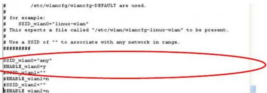
// Consult your network administrator for SSID required in your wireless network. For example, SSID_waln0="any", Enable_wlan0=y//
- Duplicate the configuration profile to a new profile.
cp /etc/wlan/wlancfg-DEFAULT /etc/wlan/wlancfg-any
// Copy configuration profile "DEFAULT" to new configuration profile "any" //
- Configure the WEP setting, if WEP is required on your wireless network.
vi /etc/wlan/wlancfg-any
![#[Dis/En]able WEP. Settings only matter if PrivacyInvoked is true lnxreq_hostWEFEncrypt=false # true|false lnxreq_hostWEFDecrypt=false # true|false dot11PrivacyInvoked=false # true|false dot11WEFDefaultKeyID=0 # 0|1|2|3 dot11ExcludeUnencrypted=false # true|false, in AP this means WEP is required. If PRIV_GENSTR is not empty, use PRIV_GENSTR to generate keys (just a convenience) PRIV_GENERATOR=/sbin/nwepgen # nwepgen, Neesus compatible PRIV_KEY12S=false # keylength to generate PRIV_GENSTR= "" or set them explicitly. Set genstr or keys, not both. dot11WEFDefaultKey0= # format: xx:xx:xx:xx:xx or dot11WEFDefaultKey1= # xx:xx:xx:xx:xx:xx:xx:xx:xx:xx:xx:xx:xx dot11WEFDefaultKey2= # e.g. 01:20:03:40:05 or dot11WEFDefaultKey3= # 01:02:03:04:05:06:07:08:09:0a:0b:0c:0d #==========SELECT STATION MODE===========IS_ACHCC=n # y/n, y - adhoc, n - infrastructure](/content/2026/06/1146084/images/82692e9bc6686f19fb01658108795b2365bb9823527e7458c065434a713ab0cd.jpg)
IEEE802.11g
The following IEEE802.11g wireless modules are supported:
• ASUS—WL-107g
• CNET—CWC-854 (181D version)
• Edmiax—EW-7108PCg
• Amigo—AWP-914W
• GigaByte—GN-WMKG
- Other brands that use the Ralink RT2500 series chip set
To configure the WLAN for IEEE802.11g:
-
Unplug the CardBus Wireless LAN card first.
-
Use the command #vi /etc/networking/interfaces to open the "interfaces" configuration file with vi editor, and then edit the 802.11g network settings (circled in red in the following figure).
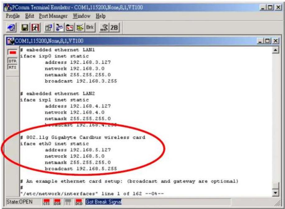
- Additional WLAN parameters are contained in the file RT2500STA.dat. To open the file, navigate to the RT2500STA folder and invoke vi, or type the following command #vi /etc/Wireless/RT2500STA/RT2500STA.dat to edit the file with vi editor. Setting options for the various parameters are listed below the figure.
![PComm Terminal Emulator - COM1,115200,None,8,1,VT100 Profile Edit Port Manager Window Help COM1,115200,None,8,1,VT100 # [Default] CountryRegion=0 WirelessMode=0 SSID=any NetworkType=Infra Channel=0 AuthMode=OPEN EncrypType=NONE DefaultKeyID=1 Key1Str=0123456789 Key2Str= Key3Str= Key4Str= WpaPsk=abcdefghijklmnopqrstuvwxyz TXBurst=0 TurboRate=0 BGProtection=0 ShortSlot=0 TxRate=0 RTSThreshold=2312 FragThreshold=2312 PSMode=CAM "/etc/Wireless/RT2500STA/RT2500STA.dat" line 1 of 34 --2%-- State:OPEN CTS DSR RI DCD Got Break Signal](/content/2026/06/1146084/images/d50552ca3948191fb3e5055c4c84af57e7b7c009359968f42506aaff6bbf2bf6.jpg)
CountryRegion—Sets the channels for your particular country / region
| Setting Explanation | ||
| 0 use channels 1 to 11 | ||
| 1 use channels 1 to 11 | ||
| 2 use channels 1 to 13 | ||
| 3 use channels 10, 11 | ||
| 4 use channels 10 to 13 | ||
| 5 | use channel | 14 |
| 6 use channels 1 to 14 | ||
| 7 use channels 3 to 9 | ||
WirelessMode—Sets the wireless mode
| Setting Explanation | ||
| 0 | 11b/g | mixed |
| 1 | 11b | only |
| 2 | 11g | only |
SSID—Sets the softAP SSID
| Setting |
| Any 32-byte string |
NetworkType—Sets the wireless operation mode
| Setting Explanation | |
| Infra Infrastructure mode (uses access points to transmit data) | |
| Adhoc Adhoc mode (transmits data from host to host) |
Channel—Sets the channel
| Setting Explanation | |
| 0 | auto |
| 1 to 14 the channel | you want to use |
AuthMode—Sets the authentication mode
| Setting |
| OPEN |
| SHARED |
| WPAPSK |
| WPANONE |
EncrypType—Sets encryption type
| Setting |
| NONE |
| WEP |
| TKIP |
| AES |
DefaultKeyID—Sets default key ID
| Setting |
| 1 to 4 |
Key1Str, Key2Str, Key3Str, Key4Str—Sets strings Key1 to Key4
| Setting |
| The keys can be input as 5 ascii characters, 10 hex numbers, 13 ascii characters, or 26 hex numbers |
TxBurst—WPA pre-shared key
| Setting |
| 8 to 64 ascii characters |
WpaPsk—Enables or disables TxBurst
| Setting Explanation | |
| 0 | disable |
| 1 | enable |
TurboRate—Enables or disables TurboRate
| Setting Explanation | |
| 0 | disable |
| 1 | enable |
BGProtection—Sets 11b/11g protection (this function is for engineering testing only)
| Setting Explanation | ||
| 0 | auto | |
| 1 | always | on |
| 2 | always | off |
ShortSlot—Enables or disables the short slot time
| Setting Explanation | |
| 0 | disable |
| 1 | enable |
TxRate—Sets the TxRate
| Setting Explanation | ||
| 0 | Auto | |
| 1 | 1 | Mbps |
| 2 | 2 | Mbps |
| 3 | 5.5 | Mbps |
| 4 | 11 | Mbps |
| 5 | 6 | Mbps |
| 6 | 9 | Mbps |
| 7 | 12 | Mbps |
| 8 | 18 | Mbps |
| 9 | 24 | Mbps |
| 10 | 36 | Mbps |
| 11 | 48 | Mbps |
| 12 | 54 | Mbps |
RTSThreshold—Sets the RTS threshold
| Setting |
| 1 to 2347 |
FragThreshold—Sets the fragment threshold
| Setting |
| 256 to 2346 |
Test Program—Developing Hello.c
In this section, we use the standard “Hello” programming example to illustrate how to develop a program for UC-7420/7410. In general, program development involves the following seven steps.
Step 1:
Connect UC-7420/7410 to a Linux PC.
Step 2:
Install Tool Chain (GNU Cross Compiler & glibc).
Step 3:
Set the cross compiler and glibc environment variables.
Step 4:
Code and compile the program.
Step 5:
Download the program to UC-7420/7410 Via FTP or NFS.
Step 6:
Debug the program
→ If bugs are found, return to Step 4.
→ If no bugs are found, continue with Step 7
Step 7:
Back up the user directory (distribute the program to additional UC-7420/7410 units if needed).
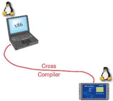
flowchart
graph TD
    A["Laptop x86"] -->|Cross Compiler| B["Monitor"]
Installing the Tool Chain (Linux)
The PC must have the Linux Operating System pre-installed before installing the UC-7420/7410 GNU Tool Chain. Redhat 7.3/8.0, Fedora core, and compatible versions are recommended. The Tool Chain requires about 100 MB of hard disk space on your PC. The UC-7420/7410 Tool Chain software is located on the UC-7420/7410 CD. To install the Tool Chain, insert the CD into your PC and then issue the following commands:
mount /dev/cdrom /mnt/cdrom
rpm -ivh /mnt/cdrom/mxscaleb-3.3.2-6.i386.rpm
The Tool Chain will be installed automatically on your Linux PC within a few minutes. Before compiling the program, be sure to set the following path first, since the ToolChain files, including the compiler, link, library, and include files are located in this directory.
PATH=/usr/local/mxscaleb/bin:\$PATH
Setting the path allows you to run the compiler from any directory.
NOTE
Refer to Appendix B for an introduction to the Windows Tool Chain. In this chapter, we use the Linux tool chain to illustrate the cross compiling process.
Checking the Flash Memory Space
If the flash memory is full, you will not be able to save data to the Flash ROM. Use the following command to calculate the amount of “Available” flash memory:
/>df -h
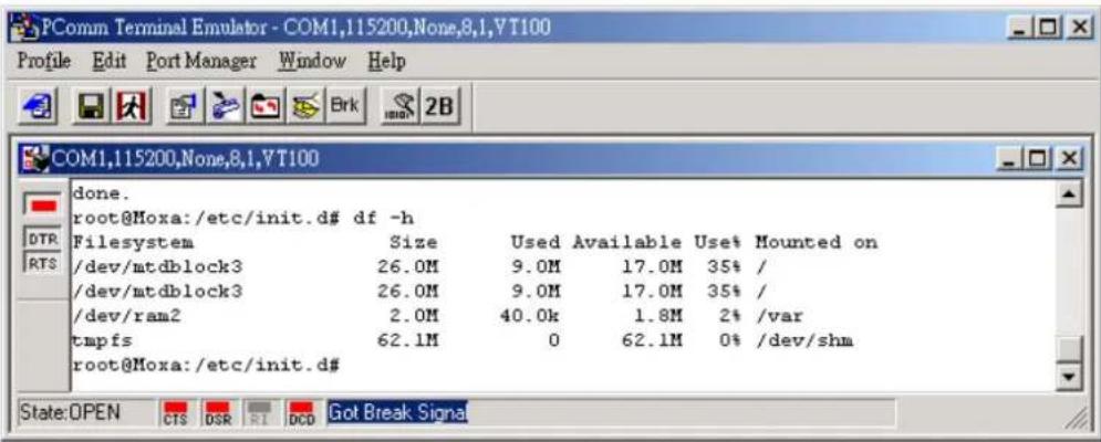
If there isn't enough "Available" space for your application, you will need to delete some existing files. To do this, connect your PC to the UC-7420/7410 with the console cable, and then use the console utility to delete the files from UC-7420/7410's flash memory.
NOTE
If the flash memory is full, you will need to free up some memory space before saving files to the Flash ROM.
Compiling Hello.c
The UC-7420/7410 CD contains several example programs. Here we use Hello.c as an example to show you how to compile and run your applications. Type the following commands from your PC to copy the files used for this example from the CD to your computer's hard drive:
<h1 id="cd-tmp">cd /tmp/</h1>
<h1 id="mkdir-example">mkdir example</h1>
<h1 id="cp-r-mntcdromexample-tmpexample">cp -r /mnt/cdrom/example/* /tmp/example</h1>
To compile the program, go to the Hello subdirectory and issue the following commands:
#cd example/hello
#make
You should receive the following response:
[root@localhost hello]# make
/usr/local/mxscaleb/bin/mxscaleb-gcc -o hello-release hello.c
/usr/local/mxscaleb/bin/mxscaleb-strip -s hello-release
/usr/local/mxscaleb/bin/mxscaleb-gcc -ggdb -o hello-debug hello.c
[root@localhost hello]# _
Next, execute the hello.exe to generate hello-release and hello-debug, which are described below:
hello-release—an IXP platform execution file (created specifically to run on UC-7420/7410)
hello-debug—an IXP platform GDB debug server execution file (see Chapter 5 for details about the GDB debug tool).
NOTE
Be sure to type the #make command from within the /tmp/example/hello directory, since UC's tool chain puts a specially designed Makefile in that directory. This special Makefile uses the mxscale-gcc compiler to compile the hello.c source code for the Xscale environment. If you type the #make command from any other directory, Linux will use the x86 compiler (for example, cc or gcc).
Refer to Chapter 5 to see a Make file example.
Uploading "Hello" to UC-7420/7410 and Running the Program
Use the following command to upload hello-release to the UC-7420/7410 via FTP.
- From the PC, type:
#ftp 192.168.3.127
- Use bin command to set the transfer mode to Binary mode, and the put command to initiate the file transfer:
ftp> bin
ftp> put hello-release
- From the UC-7420/7410, type:
<h1 id="chmod-x-hello-release">chmod +x hello-release</h1>
<h1 id="hello-release">./hello-release</h1>
The word Hello will be printed on the screen.
root@Moxa:~# ./hello-release
Hello
Developing Your First Application
We use the tcps2 example to illustrate how to build an application for UC-7420/7410. The procedure outlined in the following subsections will show you how to build a TCP Server program plus serial port communication that runs on the UC-7420/7410.
Testing Environment
The tcps2 example demonstrates a simple application program that delivers transparent, bi-directional data transmission between UC-7420/7410's serial and Ethernet ports. As illustrated in the following figure, the purpose of this application is to transfer data between PC 1 and the UC-7420/7410 via an RS-232 connection. At the remote site, data can be transferred between UC-7420/7410's Ethernet port and PC 2 over an Ethernet connection.
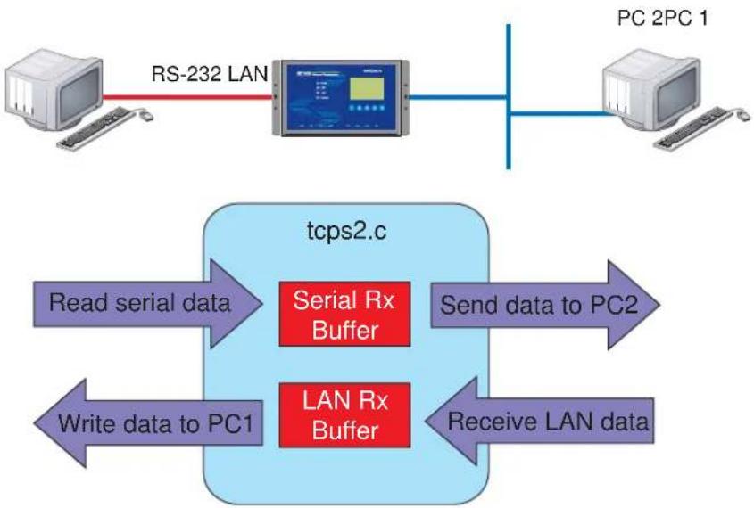
flowchart
graph TD
    A["Computer"] -->|RS-232 LAN| B["Monitor"]
    B --> C["PC 2PC 1"]
    D["Read serial data"] --> E["Serial Rx Buffer"]
    F["Write data to PC1"] --> G["LAN Rx Buffer"]
    H["Send data to PC2"] --> I["pcps2.c"]
    J["Receive LAN data"] --> I
Compiling tcps2.c
The source code for the tcps2 example is located on the CD-ROM at
CD-ROM://example/TCPServer2/tcps2.c. Use the following commands to copy the file to a specific directory on your PC. We use the directory /home/uc7400/1st_application/. Note that you need to copy 3 files—Makefile, tcps2.c, tcpsp.c—from the CD-ROM to the target directory.
#mount -t iso9660 /dev/cdrom /mnt/cdrom
#cp /mnt/cdrom/example/TCPServer2/tcps2.c/home/uc7400/1st_application/tcps2.c
#cp /mnt/cdrom/example/TCPServer2/tcpsp.c/home/uc7400/1st_application/tcpsp.c
#cp /mnt/cdrom/example/TCPServer2/Makefile.c/home/uc7400/1st_application/Makefile.c
Type #make to compile the example code:
You will get the following response, indicating that the example program was compiled successfully.
root@server11:/home/uc7400/1st_application
[root@server11 1st_application]# pwd
/home/uc7400/1st_application
[root@server11 1st_application]# 11
total 20
-rw-r-r-- 1 root root 514 Nov 27 11:52 Makefile
-rw-r-r-- 1 root root 4554 Nov 27 11:52 tcps2.c
-rw-r-r-- 1 root root 6164 Nov 27 11:55 tcps2.c
[root@server11 1st_application]# make_
/usr/local/mxscaleb/bin/mxscaleb-gcc -o tcps2-release tcps2.c
/usr/local/mxscaleb/bin/mxscaleb-strip -s tcps2-release
/usr/local/mxscaleb/bin/mxscaleb-gcc -o tcpsp-release tcpsp.c
/usr/local/mxscaleb/bin/mxscaleb-strip -s tcpsp-release
/usr/local/mxscaleb/bin/mxscaleb-gcc -ggdb -o tcps2-debug tcps2.c
/usr/local/mxscaleb/bin/mxscaleb-gcc -ggdb -o tcpsp-debug tcpsp.c
You have new mail in /var/spool/mail/root
[root@server11 1 ^25 _application]# 11
total 92
-rw-r--r-- 1 root root 514 Nov 27 11:52 Makefile
-rwxr-xr-x 1 root root 25843 Nov 27 12:03 tcps2-debug
-rwxr-xr-x 1 root root 4996 Nov 27 12:03 tcps2-release
-rw-r--r-- 1 root root 4554 Nov 27 11:52 tcps2.c
-rwxr-xr-x 1 root root 26823 Nov 27 12:03 tcpsp-debug
-rwxr-xr-x 1 root root 5396 Nov 27 12:03 tcpsp-release
-rw-r--r-- 1 root root 6164 Nov 27 11:55 tcpsp.c
[root@server11 1st_application]#
Two executable files, tcps2-release and tcps2-debug, are created.
tcps2-release—an IXP platform execution file (created specifically to run on UC-7420/7410)
tcps2-debug—an IXP platform GDB debug server execution file (see Chapter 5 for details about the GDB debug tool).
NOTE
If you get an error message at this point, it could be because you neglected to put tcps2.c and tcpsp.c in the same directory. The example Makefile we provide is set up to compile both tcps2 and tcpsp into the same project Makefile. Alternatively, you could modify the Makefile to suit your particular requirements.
Uploading tcps2-release and Running the Program
Use the following commands to use FTP to upload tcps2-release to the UC-7420/7410.
- From the PC, type:
#ftp 192.168.3.127
- Next, use the bin command to set the transfer mode to Binary, and the put command to initiate the file transfer:
ftp> bin
ftp> put tcps2-release
root@server11:/home/uc7400/1st_application
[root@server11 1st_application]# ftp 192.168.3.127
Connected to 192.168.3.127
220 Moxa FTP server (Version wu-2.6.1(2) Mon Nov 24 12:17:04 CST 2003) ready.
530 Please login with USER and PASS.
530 Please login with USER and PASS.
KERBEROS_V4 rejected as an authentication type
Name (192.168.3.127:root): root
331 Password required for root.
Password:
230 User root logged in.
Remote system type is UNIX.
Using binary mode to transfer files.
ftp> bin
200 Type set to I.
ftp> put tcps2-release
local: tcps2-release remote: tcps2-release
277 Entering Passive Mode (192.168.3.127.82.253)
150 Opening BINARY mode data connection for tcps2-release.
226 Transfer complete
4996 bytes sent in 0.00013 seconds (3.9e+04 Kbytes/s)
ftp> ls
227 Entering Passive Mode (192.168.3.127.106.196)
150 Opening ASCII mode data connection for /bin/ls.
-rw---- 1 root root 899 Jun 10 08:11 bash_history
-rw-r--r-- 1 root root 4996 Jun 12 02:15 tcps2-release
226 Transfer complete
ftp>
- From the UC-7420/7410, type:
<h1 id="chmod-x-tcps2-release">chmod +x tcps2-release</h1>
<h1 id="tcps2-release">./tcps2-release &</h1>
192.168.3.127 - PuTTY
root@Moxa:~# ls -al
drwxr-xr-x 2 root root 0 Jun 12 02:14
drwxr-xr-x 15 root root 0 Jan 1 1970
-rw---- 1 root root 899 Jun 10 08:11 .bash_history
-rw-r--r-- 1 root root 4996 Jun 12 02:15 tcps2-release
root@Moxa:~# chmod +x tcps2-release
root@Moxa:~# ls -al
drwxr-xr-x 2 root root 0 Jun 12 02:14
drwxr-xr-x 15 root root 0 Jan 1 1970
-rw---- 1 root root 899 Jun 10 08:11 .bash_history
-rwxr-xr-x 1 root root 4996 Jun 12 02:15 tcps2-release
root@Moxa:~#
- The program should start running in the background. Use either the #jobs or #ps -ef command to check if the tcps2 program is actually running in the background.
jobs // use this command to check if the program is running
192.168.3.127 - PuTTY
root@Moxa:~# ls -al
drwxr-xr-x 2 root root 0 Jun 12 02:14
drwxr-xr-x 15 root root 0 Jan 1 1970
-rw---- 1 root root 899 Jun 10 08:11 .bash_history
-rw-r--r-- 1 root root 4996 Jun 12 02:15 tcps2-release
root@Moxa:~# chmod +x tcps2-release
root@Moxa:~# ls -al
drwxr-xr-x 2 root root 0 Jun 12 02:14
drwxr-xr-x 15 root root 0 Jan 1 1970
-rw---- 1 root root 899 Jun 10 08:11 .bash_history
-rwxr-xr-x 1 root root 4996 Jun 12 02:15 tcps2-release
root@Moxa:~# ./tcps2-release &
[1] 187
start
root@Moxa:~# jobs
[1]+ Running ./tcps2-release &
root@Moxa:~#
NOTE Use the
kill command for job number 1 to terminate this program: #kill %1
ps -ef // use this command to check if the program is running
192.168.3.127 - PuTTY
[1]+ Running ./tcps2-release & root@Moxa:~# ps -ef
PID Uid VmSize Stat Command
1 root 1296 S init
2 root S [keventd]
3 root S [ksoftirqd_CPU0]
4 root S [kswapd]
5 root S [bdflush]
6 root S [kupdated]
7 root S [mtdblockd]
8 root S [khubd]
10 root S [jffs2_gcd_mtd3]
32 root D [ixp425_csr]
34 root S [ixp425 ixp0]
36 root D [ixp425 ixpl]
38 root 1256 S stdef
46 root 1368 S /usr/sbin/inetd
52 root 4464 S /usr/sbin/httpd
53 nobody 4480 S /usr/sbin/httpd
54 nobody 4480 S /usr/sbin/httpd
64 nobody 4480 S /usr/sbin/httpd
65 nobody 4480 S /usr/sbin/httpd
66 nobody 4480 S /usr/sbin/httpd
88 bin 1460 S /sbin/portmap
100 root 1556 S /usr/sbin/rpc.statd
104 root 4044 S /usr/sbin/snmpd -s -l /dev/null
106 root 2832 S /usr/sbin/snmptrapd -s
135 root 1364 S /sbin/cardmgr
139 root 1756 S /usr/sbin/rpc.nfsd
141 root 1780 S /usr/sbin/rpc.mountd
148 root 2960 S /usr/sbin/sshd
156 root 1272 S /bin/reportip
157 root 1532 S /sbin/getty 115200 ttyS0
NOTE Use the kill -9 command for PID 187 to terminate this program: #kill -9 %187
Testing Procedure Summary
- Compile tcps2.c (#make).
- Upload and run tcps2-release in the background (#. /tcps2-release &).
- Check that the process is running ( #jobs or #ps -ef).
- Use a serial cable to connect PC1 to UC-7420/7410's serial port 1.
- Use an Ethernet cable to connect PC2 to UC-7420/7410.
- On PC1: If running Windows, use HyperTerminal (38400, n, 8, 1) to open COMn.
- On PC2: Type #telnet 192.168.3.127 4001.
- On PC1: Type some text on the keyboard and then press Enter.
- On PC2: The text you typed on PC1 will appear on PC2's screen.
The testing environment is illustrated in the following figure. However, note that there are limitations to the example program tcps2.c.
PC 1
PC 2
RS-232 LAN
tcps2.c
Read serial data
Send data to PC2
Write data to PC1
Receive LAN data
NOTE
The tcps2.c application is a simple example designed to give users a basic understanding of the concepts involved in combining Ethernet communication and serial port communication. However, the example program has some limitations that make it unsuitable for real-life applications.
- The serial port is in canonical mode and block mode, making it impossible to send data from the Ethernet side to the serial side (i.e., from PC 2 to PC 1 in the above example).
- The Ethernet side will not accept multiple connections.
This chapter includes information about version control, deployment, updates, and peripherals. The information in this chapter will be particularly useful when you need to run the same application on several UC-7420/7410 units.
The following topics are covered in this chapter:
□ System Version Information
□ System Image Backup
▶ Upgrading the Firmware
➢ Loading Factory Defaults
□ Enabling and Disabling Daemons
Setting the Run-Level
□ Adjusting the System Time
➢ Setting the Time Manually
NTP Client
➢ Updating the Time Automatically
□ Cron—daemon to Execute Scheduled Commands
□ Connecting Peripherals
USB Mass Storage
CF Mass Storage
System Version Information
To determine the hardware capability of your UC-7420/7410, and what kind of software functions are supported, check the version numbers of your UC-7420/7410's hardware, kernel, and user file system. Contact Moxa to determine the hardware version. You will need the Production S/N (Serial number), which is located on UC-7420/7410's bottom label.
To check the kernel version, type:
kversion
To check the user file system version, type: #fsversion
192.168.3.127 - PuTTY
root@Moxa:~# kversion
1.4.3
root@Moxa:~# fsversion
1.4.3
root@Moxa:~#
NOTE
The kernel version and user file system version numbers are the same for the factory default configuration, and if you download the latest firmware version from Moxa's website and then upgrade UC-7420/7410's hardware, the two version numbers will be the same.
However, to help users define the user file system, the kernel and user file system are separate, and hence could have different version numbers. For this reason, we provide two utilities, called kversion and fsversion, that allow you to check the version numbers of the kernel and file system, respectively.
System Image Backup
Upgrading the Firmware
UC-7420/7410's bios, kernel, mini file system, and user file system are combined into one firmware file, which can be downloaded from Moxa's website (www.moxa.com). The name of the file has the form uc7400-x.x.x.frm, with "x.x.x" indicating the firmware version. To upgrade the firmware, download the firmware file to a PC, and then transfer the file to the UC-7420/7410 unit via a serial Console or Telnet Console connection.

ATTENTION
Upgrading the firmware will erase all data on the Flash ROM
If you are using the ramdisk to store code for your applications, beware that updating the firmware will erase all of the data on the Flash ROM. You should back up your application files and data before updating the firmware.
Since different Flash disks have different sizes, it's a good idea to check the size of your Flash disk before upgrading the firmware, or before using the disk to store your application and data files. Use the #df -h command to list the size of each memory block, and how much free space is available in each block.
192.168.3.127 - PuTTY
root@Moxa:~# df -h
Filesystem Size Used Available Use% Mounted on /dev/mtdblock3 26.0M 8.9M 17.1M 34% /
/dev/mtdblock3 26.0M 8.9M 17.1M 34% /
/dev/ram2 2.0M 40.0k 1.8M 2% /var
tmpfs 62.1M 0 62.1M 0% /dev/shm
root@Moxa:~# upramdisk
root@Moxa:~# df -h
Filesystem Size Used Available Use% Mounted on /dev/mtdblock3 26.0M 8.9M 17.1M 34% /
/dev/mtdblock3 26.0M 8.9M 17.1M 34% /
/dev/ram2 2.0M 40.0k 1.8M 2% /
tmpfs 62.1M 0 62.1M 0% /dev/shm
/dev/ram1 29.0M 13.0k 27.5M 0% /mnt/ramdisk
root@Moxa:~# cd /mnt/ramdisk
root@Moxa:/mnt/ramdisk#
The following instructions give the steps required to save the firmware file to UC-7420/7410's RAM disk, and then upgrade the firmware.
- Type the following commands to enable the RAM disk:
- Type the following commands to use UC-7420/7410's built-in FTP client to transfer the firmware file (uc7400-x.x.x.frm) from the PC to UC-7420/7410:
/mnt/ramdisk> ftp <destination PC's IP>
Login Name: xxxx
Login Password: xxxx
ftp> bin
ftp> get uc7400-x.x.x.frm
192.168.3.127 - PuTTY
root@Moxa:/mnt/ramdisk# ftp 192.168.3.193
Connected to 192.168.3.193 (192.168.3.193).
220 TYPSoft FTP Server 1.10 ready...
Name (192.168.3.193:root): root
331 Password required for root.
Password:
230 User root logged in.
Remote system type is UNIX.
Using binary mode to transfer files.
ftp> cd newsw
250 CWD command successful. "/C:/ftproot/newsw/" is current directory.
ftp> bin
200 Type set to I.
ftp> ls
200 Port command successful.
150 Opening data connection for directory list.
drw-rw-rw- 1 ftp ftp 0 Nov 30 10:03 .
drw-rw-rw- 1 ftp ftp 0 Nov 30 10:03 .
-rw-rw-rw- 1 ftp ftp 13167772 Nov 29 10:24 UC7420-1.5.frm
-rw-rw-rw- 1 ftp ftp 8778996 Nov 29 10:24 UC7420_usrdisk-1.5.frm
226 Transfer complete.
ftp> get UC7420-1.5.frm
local: UC7420-1.5.frm remote: UC7420-1.5.frm
200 Port command successful.
150 Opening data connection for UC7420-1.5.frm
226 Transfer complete.
13167772 bytes received in 2.17 secs (5925.8 kB/s)
ftp>
- Next, use the upfirm command to upgrade the kernel and root file system:
upfirm uc7400-x.x.x.frm
192.168.3.127 - PuTTY

root@Moxa:/mnt/ramdisk# upfirm UC7420-1.5.frm
Upgrade firmware utility version 1.0.
To check source firmware file context.
The source firmware file context is OK.
This step will destroy all your firmware.
Do you want to continue it ? (Y/N) : Y
Now upgrade the file [redboot].
Format MTD device [/dev/mtd0] . . .
MTD device [/dev/mtd0] erase 128 Kibyte @ 60000 - 100% complete.
Wait to write file . . .
Completed 100%
Now upgrade the file [kernel].
Format MTD device [/dev/mtd1] . . .
MTD device [/dev/mtd1] erase 128 Kibyte @ 100000 - 100% complete.
Wait to write file . . .
Completed 100%
Now upgrade the file [mini-file-system].
Format MTD device [/dev/mtd2] . . .
MTD device [/dev/mtd2] erase 128 Kibyte @ 400000 - 100% complete.
Wait to write file . . .
Completed 100%
Now upgrade the file [user-file-system].
Format MTD device [/dev/mtd3] . . .
MTD device [/dev/mtd3] erase 128 Kibyte @ 1a00000 - 100% complete.
Wait to write file . . .
Completed 100%
Now upgrade the file [directory].
Format MTD device [/dev/mtd6] . . .
MTD device [/dev/mtd6] erase 128 Kibyte @ 20000 - 100% complete.
Wait to write file . . .
Completed 100%
Now upgrade the new configuration file.
Upgrade the firmware is OK.
Please press any key to reboot system.
Loading Factory Defaults
The easiest way to load factory defaults is to update the firmware (follow the instructions in the previous section to upgrade the firmware).
Note that if your user file is not working properly, the system will mount the Mini File System. In this case, you will need to load factory defaults to resume normal operation.
Enabling and Disabling Daemons
The following daemons are enabled when UC-7420/7410 boots up for the first time.
snmpd ......SNMP Agent daemon
telnetd......Telnet Server / Client daemon
inetd....Internet Daemons
ftpd......FTP Server / Client daemon
sshd ......Secure Shell Server daemon
httpd ......Apache WWW Server daemon
nfsd ......Network File System Server daemon
Type the command "ps -ef" to list all processes currently running.
192.168.3.127 - PuTTY
root@Moxa:~# cd /etc
root@Moxa:/etc# ps -ef
PID Uid VmSize Stat Command
1 root 1296 S init
2 root S [keventd]
3 root S [ksoftirqd_CPU0]
4 root S [kswapd]
5 root S [bdfush]
6 root S [kupdated]
7 root S [mtdblockd]
8 root S [khubd]
10 root S [jffs2_gcd_mtd3]
32 root D [ixp425_csr]
34 root S [ixp425 ixp0]
38 root 1256 S stdef
36 root S [ixp425 ixpl]
47 root 1368 S /usr/sbin/inetd
53 root 4464 S /usr/sbin/httpd
54 nobody 4480 S /usr/sbin/httpd
64 nobody 4480 S /usr/sbin/httpd
65 nobody 4480 S /usr/sbin/httpd
66 nobody 4480 S /usr/sbin/httpd
67 nobody 4480 S /usr/sbin/httpd
92 bin 1460 S /sbin/portmap
104 root 1556 S /usr/sbin/rpc.statd
108 root 4044 S /usr/sbin/snmpd -s -l /dev/null
110 root 2828 S /usr/sbin/snmptrapd -s
139 root 1364 S /sbin/cardmgr
143 root 1756 S /usr/sbin/rpc.nfsd
145 root 1780 S /usr/sbin/rpc.mountd
152 root 2960 S /usr/sbin/sshd
160 root 1272 S /bin/reportip
161 root 3464 S /bin/massupfirm
162 root 1532 S /sbin/getty 115200 ttyS01
163 root 1532 S /sbin/getty 115200 ttyS1
166 root 3464 S /bin/massupfirm
167 root 3464 S /bin/massupfirm
170 root 3652 S /usr/sbin/sshd
171 root 2196 S -bash
182 root 1592 S ps -ef
root@Moxa:/ect#
To run a private daemon, you can edit the file rc.local, as follows:
cd /etc/rc.d
vi rc.local
192.168.3.127 - PuTTY
root@Moxa:~# cd /etc/rc.d
root@Moxa:/etc/rc.d# vi rc.local
Next, use the vi open your application program. We use the example program tcps2-release, and put it to run in the background.
192.168.3.127 - PuTTY
#!/bin/sh
<h1 id="add-you-want-to-run-daemon-roottcps2-release">Add you want to run daemon /root/tcps2-release &~</h1>
Then you will find the enabled daemons after you reboot the system.
192.168.3.127 - PuTTY
root@Moxa:~# ps -ef
PID Uid VmSize Stat Command
1 root 1296 S init
2 root S [keventd]
3 root S [ksoftirqd_CPU0]
4 root S [kswapd]
5 root S [bdflush]
6 root S [kupdated]
7 root S [mtdblockd]
8 root S [khubd]
10 root S [jffs2_gcd_mtd3]
32 root D [ixp425_csr]
34 root S [ixp425 ixp0]
36 root S [ixp425 ixpl]
38 root 1256 S stdef
47 root 1368 S /usr/sbin/inetd
53 root 4464 S /usr/sbin/httpd
63 nobody 4480 S /usr/sbin/httpd
64 nobody 4480 S /usr/sbin/httpd
65 nobody 4480 S /usr/sbin/httpd
66 nobody 4480 S /usr/sbin/httpd
67 nobody 4480 S /usr/sbin/httpd
92 bin 1460 S /sbin/portmap
97 root 1264 S /root/tcps2-release
105 root 1556 S /usr/sbin/rpc.statd
109 root 4044 S /usr/sbin/snmpd -s -l /dev/null
111 root 2832 S /usr/sbin/snmptrapd -s
140 root 1364 S /sbin/cadmgr
144 root 1756 S /usr/sbin/rpc.nfsd
146 root 1780 S /usr/sbin/rpc.mountd
153 root 2960 S /usr/sbin/sshd
161 root 1272 S /bin/reportip
162 root 3464 S /bin/massupfirm
163 root 1532 S /sbin/getty 115200 ttyS0
164 root 1532 S /sbin/getty 115200 ttyS1
166 root 3464 S /bin/massupfirm
168 root 3464 S /bin/massupfirm
171 root 3652 S /usr/sbin/sshd
172 root 2200 S -bash
174 root 1592 S ps -ef
root@Moxa:~#
Setting the Run-Level
In this section, we outline the steps you should take to set the Linux run-level and execute requests. Use the following command to enable or disable settings:
192.168.3.127 - PuTTY
root@Moxa:/ect/rc.d/rc3.d# ls
S19nfs-common S25nfs-user-server S99showreadyled
S20snmpd S55ssh
S24pcmcia S99rmnologin
root@Moxa:/etc/rc.d/rc3.d#
cd /etc/rc.d/init.d
Edit a shell script to execute /root/tcps2-release and save to tcpps2 as an example.
#cd /etc/rc.d/rc3.d
#ln -s /etc/rc.d/init.d/tcps2 S60tcps2
SxxRUNFILE stands for
S: start the run file while linux boots up.
xx: a number between 00-99. The smaller number has a higher priority.
RUNFILE: the file name.
192.168.3.127 - PuTTY
root@Moxa:/ect/rc.d/rc3.d# ls
S19nfs-common S25nfs-user-server S99showreadyled
S20snmpd S55ssh
S24pcmcia S99rmnologin
root@Moxa:/ect/rc.d/rc3.d# ln -s /root/tcps2-release S60tcps2
root@Moxa:/ect/rc.d/rc3.d# ls
S19nfs-common S25nfs-user-server S99rmnologin
S20snmpd S55ssh S99showreadyled
S24pcmcia S60tcps2
root@Moxa:/etc/rc.d/rc3.d#
KxxRUNFILE stands for
K: start the run file while linux shuts down or halts.
xx: a number between 00-99. The smaller number has a higher priority.
RUNFILE: is the file name.
For removing the daemon, you can remove the run file from /etc/rc.d/rc3.d by using the following command:
#rm -f /etc/rc.d/rc3.d/S60tcps2
Adjusting the System Time
Setting the Time Manually
UC-7420/7410 has two time settings. One is the system time, and the other is the RTC (Real Time Clock) time kept by the UC-7420/7410 hardware. Use the #date command to query the current system time or set a new system time. Use #hwclock to query the current RTC time or set a new RTC time.
Use the following command to query the system time: #date
Use the following command to query the RTC time: #hwclock
Use the following command to set the system time:
date MMDDhhmmYYYY
MM = Month
DD = Date
hhmm = hour and minute
YYYY = Year
Use the following command to set the RTC time: #hwclock -w
Write current system time to RTC
The following figure illustrates how to update the system time and set the RTC time.
192.168.3.127 - PuTTY
root@Moxa:~# date
Fri Jun 23 23:30:31 CST 2000
root@Moxa:~# hwclock
Fri Jun 23 23:30:35 2000 -0.557748 seconds
root@Moxa:~# date 120910002004
Thu Dec 9 10:00:00 CST 2004
root@Moxa:~# hwclock -w
root@Moxa:~# date ; hwclock
Thu Dec 9 10:01:07 CST 2004
Thu Dec 9 10:01:08 2004 -0.933547 seconds
root@Moxa:~#
NTP Client
UC-7420/7410 has a built-in NTP (Network Time Protocol) client that is used to initialize a time request to a remote NTP server. Use #ntpdate
#ntpdate time.stdtime.gov.tw
#hwclock -w
Visit http://www.ntp.org for more information about NTP and NTP server addresses.
10.120.53.100 - PuTTY
root@Moxa:~# date ; hwclock
Sat Jan 1 00:00:36 CST 2000
Sat Jan 1 00:00:37 2000 -0.772941 seconds
root@Moxa:~# ntpdate time.stdtion.gov.tw
9 Dec 10:58:53 ntpdate[207]: step time server 220.130.158.52 offset 155905087.9
84256 sec
root@Moxa:~# hwclock -w
root@Moxa:~# date ; hwclock
Thu Dec 9 10:59:11 CST 2004
Thu Dec 9 10:59:12 2004 -0.844076 seconds
root@Moxa:~#
NOTE
Before using the NTP client utility, check your IP and DNS settings to make sure that an Internet connection is available. Refer to Chapter 2 for instructions on how to configure the Ethernet interface, and see Chapter 4 for DNS setting information.
Updating the Time Automatically
In this subsection we show how to use a shell script to update the time automatically.
Example shell script to update the system time periodically
#!/bin/sh
ntpdate time.nist.gov # You can use the time server's ip address or domain
<h1 id="name-directly-if-you-use-domain-name-you-must">name directly. If you use domain name, you must</h1>
<h1 id="enable-the-domain-client-on-the-system-by-updating">enable the domain client on the system by updating</h1>
<h1 id="etcresolvconf-file">/etc/resolv.conf file.</h1>
hwclock -systohc
sleep 100 # Updates every 100 seconds. The min. time is 100 seconds. Change # 100 to a larger number to update RTC less often.
Save the shell script using any file name. E.g., fixtime
How to run the shell script automatically when the kernel boots up
Copy the example shell script fixtime to directory /etc/init.d, and then use chmod 755 fixtime to change the shell script mode. Next, use vi editor to edit the file /etc/inittab. Add the following line to the bottom of the file:
Use the command #init q to re-init the kernel.
Cron—daemon to Execute Scheduled Commands
This function is only available for firmware version V1.5 (and later versions). Start Cron from the directory /etc/rc.d/rc.local. It will return immediately, so you don't need to start it with '&' to run the background.
The Cron daemon will search /etc/cron.d/crontab for crontab files, which are named after accounts in /etc/passwd.
Cron wakes up every minute, and checks each command to see if it should be run in the current minute.
Modify the file /etc/cron.d/crontab to set up your scheduled applications. Crontab files have the following format:
| mm | h | dom | mon | dow | user | command | |
| month | hour | date | month | week | user | command | |
| 0-59 | 0-23 | 1-31 | 1-12 | 0-6 | (0 is Sunday) | ||
The following example demonstrates how to use Cron.
How to use cron to update the system time and RTC time every day at 8:00.
STEP1: Write a shell script named fixtime.sh and save it to /home/.
#!/bin/sh
ntpdate time.nist.gov
hwclock -systohc
exit 0
STEP2: Change mode of fixtime.sh
#chmod 755 fixtime.sh
STEP3: Modify /etc/cron.d/crontab file to run fixtime.sh at 8:00 every day.
Add the following line to the end of crontab:
* 8 * * * root /home/fixtime.sh
STEP4: Enable the cron daemon manually.
#/etc/init.d/cron start
STEP5: Enable cron when the system boots up.
Add the following line in the file /etc/init.d/rc.local
#/etc/init.d/cron start
Connecting Peripherals
USB Mass Storage
This function is only available for firmware version V1.5 (and later versions).
The UC-7420/7410 supports PNP (plug-n-play), and hot pluggability for connecting USB mass storage devices. UC-7420/7410 has a built-in auto mount utility that eases the mount procedure. The first connected USB mass storage device will be mounted automatically by mount to /mnt/sda, and the second device will be mounted automatically to /mnt/sdb. UC-7420/7410 will be un-mounted automatically with umount when the device is disconnected.

ATTENTION
Remember to type the #sync command before you disconnect the USB mass storage device. If you don't issue the command, you may lose some data.
Remember to exit the /mnt/sda or /mnt/sdb directory when you disconnect the USB mass storage device. If you stay in /mnt/sda or /mnt/sda, the auto un-mount process will fail. If that happens, type #umount /mnt/sda to un-mount the USB device manually.
UC-7420/7410 only supports certain types of flash disk USB Mass Storage device. Some the USB flash disks and hard disks may not be compatible with UC-7420/7410. Check compatibility issues before you purchase a USB device to connect to UC-7420/7410.
CF Mass Storage
The UC-7420/7410 supports PNP and hot pluggability for connecting a CF mass storage device.
UC-7420/7410 has a built-in auto mount utility that eases the mount procedure. The CF mass storage device will be mounted automatically by the mount command to /mnt/hda.
UC-7420/7410 will be un-mounted automatically by umount when you disconnect it.
In this chapter, we explain how to configure UC-7420/7410's various communication functions.
The following topics are covered in this chapter:
Telnet / FTP
DNS
□ Web Service—Apache
Saving a Web Page to the CF Card
□ IPTABLES
□ NAT
NAT Example
➢ Enabling NAT at Bootup
□ Dial-up Service—PPP
□ PPPoE
□ NFS (Network File System)
Setting up UC-7420/7410 as an NFS Server
Setting up UC-7420/7410 as an NFS Client
➢ Setting up UC-7420/7410 as an NFS Server
➢ Setting up UC-7420/7410 as an NFS Client
Mail
SNMP
Open VPN
Telnet / FTP
In addition to supporting Telnet client/server and FTP client/server, the UC-7420/7410 system also supports SSH and sftp client/server. To enable or disable the Telnet/ftp server, you first need to edit the file /etc/inetd.conf.
Enabling the Telnet/ftp server
The following example shows the default content of the file /etc/inetd.conf. The default is to enable the Telnet/ftp server:
discard dgram udp wait root /bin/discard discard stream tcp nowait root /bin/discard telnet stream tcp nowait root /bin/telnetd ftp stream tcp nowait root /bin/ftpd -l
Disabling the Telnet/ftp server
Disable the daemon by typing ‘#’ in front of the first character of the row to comment out the line.
DNS
UC-7420/7410 supports DNS client (but not DNS server). To set up DNS client, you need to edit three configuration files: /etc/hosts, /etc/resolv.conf, and /etc/nsswitch.conf.
/etc/hosts
This is the first file that the Linux system reads to resolve the host name and IP address.
/etc/resolv.conf
This is the most important file that you need to edit when using DNS for the other programs. For example, before you using #ntupdate time.nist.goc to update the system time, you will need to add the DNS server address to the file. Ask your network administrator which DNS server address you should use. The DNS server's IP address is specified with the "nameserver" command. For example, add the following line to /etc/resolv.conf if the DNS server's IP address is 168.95.1.1:
nameserver 168.95.1.1
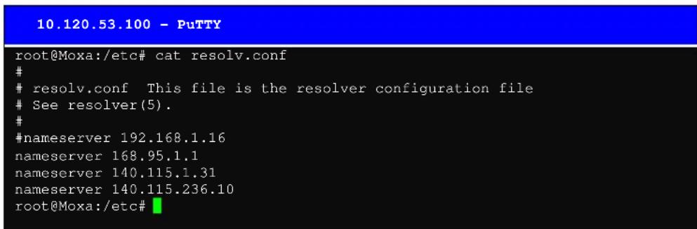
/etc/nsswitch.conf
This file defines the sequence to resolve the IP address by using /etc/hosts file or /etc/resolv.conf.
Web Service—Apache
The Apache web server's main configuration file is /etc/apache/httpd.conf, with the default homepage located at /usr/www/html/index.html. Save your own homepage to the following directory:
/usr/www/html/
Save your CGI page to the following directory:
/usr/www/cgi-bin/
Before you modify the homepage, use a browser (such as Microsoft Internet Explore or Mozilla Firefox) from your PC to test if the Apache Web Server is working. Type the LAN1 IP address in the browser's address box to open the homepage. E.g., if the default IP address is still active, type http://192.168.3.127 in address box.
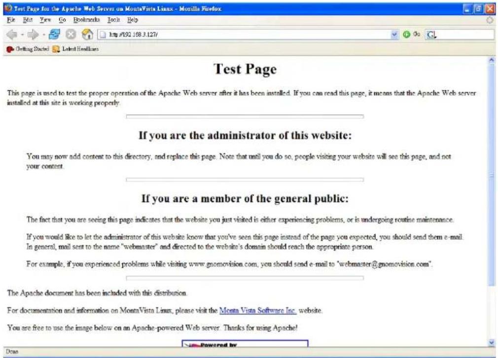
To open the default CGI page, type http://192.168.3.127/cgi-bin/printenv in your browser's address box.
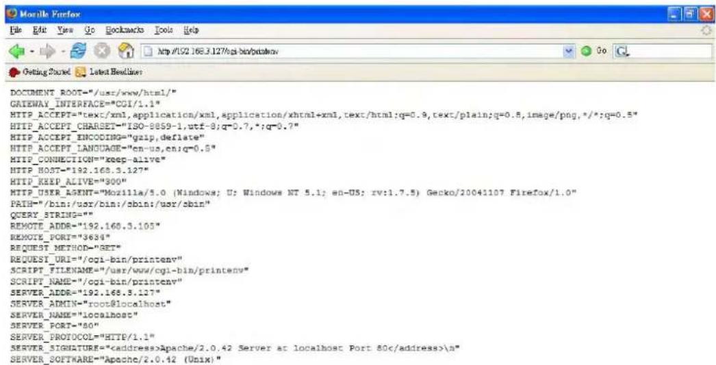
To open the default CGI test script report page, type http://192.168.3.127/cgi-bin/test-cgi in your browser's address box.
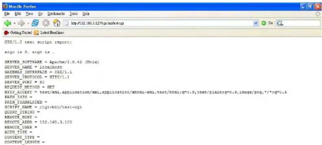
NOTE
The CGI function is enabled by default. If you want to disable the function, modify the file /etc/apache/httpd.conf. When you develop your own CGI application, make sure your CGI file is executable.
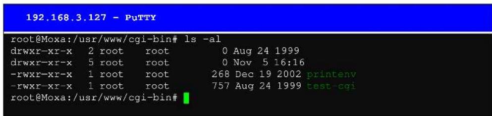
Saving a Web Page to the CF Card
Since some applications will have web pages that take up a lot of memory space, you will need to be able to run the homepage and other pages from the CF card. In this section, we use a simple example to illustrate how to save web pages to the CF card, and then configure the Apache web server to open the pages. The files used in this example can be downloaded from Moxa's website.
Step 1:
Prepare web page and put pages to CF card. Click on the following link to download the web page test suite: http://www.w3.org/MarkUp/Test/HTML401.zip. Uncompress the zip file to your desktop PC, and then use FTP to transfer it to UC-7420's /mnt/hda directory.
192.168.3.127 - PuTTY
root@Moxa:/mnt/hda# ls -al
drwxr-xr-x 4 root root 16384 Dec 11 14:18
drwxr-xr-x 6 root root 0 Sep 29 17:43
-rwxr-xr-x 1 root root 1768 Dec 11 14:16 W3C.gif
drwxr-xr-x 2 root root 4096 Dec 11 14:19 assertions
-rwxr-xr-x 1 root root 36071 Dec 11 14:18 htmltestdocument
taml
-rwxr-xr-x 1 root root 3145 Dec 11 14:16 index.html
-rwxr-xr-x 1 root root 90 Dec 11 14:17 section.css
drwxr-xr-x 2 root root 24576 Dec 11 14:20 tests
-rwxr-xr-x 1 root root 2303 Dec 11 14:16 vh401.gif
root@Moxa:/mnt/hda#
Step 2:
Use the following commands to configure the Apache web server's DocumentRoot:
cd /etc/apache
vi httpd.conf
••••••
DocumentRoot "/mnt/hda" //Change the document root directory //to your CF card.
......
192.168.3.127 - PuTTY
ServerRoot "/etc/apache"
PidFile /var/run/httpd.pid
ScoreBoardFile /var/run/httpd.scoreboard
Timeout 300
KeepAlive On
MaxKeepAliveRequests 100
KeepAliveTimeout 15
MinSpareServers 5
MaxSpareServers 10
StartServers 5
MaxClients 150
MaxRequestsPerChild 0
Listen 80
User nobody
Group nobody
ServerAdmin root@localhost
ServerName localhost
DocumentRoot "/mnt/had"
Step 3:
Use the following commands to restart the Apache web server:
cd /etc/init.d
# ./apache restart
Step4:
Open your browser and connect to the UC-7420/7410 by typing the current LAN1 IP address in the browser's address box.

HTML4 Test Suite
Contents
- HTML Test Suite Documentation - Documentation for the HTML4.01 Test Suite
- HTML Test Suite Assertions - Assertions from the W3C HTML 4.01 Specification
- HTML Test Suite Tests - Tests created to test assertions from the W3C HTML 4.01 Specification
Feedback regarding the HTML4 Test Suite should be sent to www-html-testsuite@w3.org.
The HTML4 Test Suite is an effort of the World Wide Web Consortium based on a contribution (Copyright Microsoft Corporation. All Rights Reserved, 2002) from Microsoft on behalf of Microsoft Corporation. Openwave Systems Inc. and America Online Inc. Copyright ©2002-2003 WDC® (MIT, ERCIM, Keio). All Rights Reserved. W3C liability trademark, document use and software licensing rules apply.
W3C
NOTE
Visit the Apache website at http://httpd.apache.org/docs/ for more information about setting up an Apache server.
IPTABLES
IPTABLES is an administrative tool for setting up, maintaining, and inspecting the Linux kernel's IP packet filter rule tables. Several different tables are defined, with each table containing built-in chains and user-defined chains.
Each chain is a list of rules that apply to a certain type of packet. Each rule specifies what to do with a matching packet. A rule (such as a jump to a user-defined chain in the same table) is called a "target."
UC-7420/7410 supports 3 types of IPTABLES table: Filter tables, NAT tables, and Mangle tables:
A. Filter Table—includes three chains:
INPUT chain
OUTPUT chain
FORWARD chain
B. NAT Table—includes three chains:
PREROUTING chain—transfers the destination IP address (DNAT)
POSTROUTING chain—works after the routing process and before the Ethernet device process to transfer the source IP address (SNAT)
OUTPUT chain—produces local packets
sub-tables
Source NAT (SNAT) changes the first source packet IP address
Destination NAT (DNAT)—changes the first destination packet IP address
MASQUERADE — a special form for SNAT. If one host can connect to internet, then other computers that connect to this host can connect to the Internet when it the computer does not have an actual IP address.
REDIRECT a special form of DNAT that re-sends packets to a local host independent of the destination IP address.
C. Mangle Table—includes two chains
PREROUTING chain pre-processes packets before the routing process.
OUTPUT chain—processes packets after the routing process.
It has three extensions TTL, MARK, TOS.
The following figure shows the IPTABLES hierarchy.
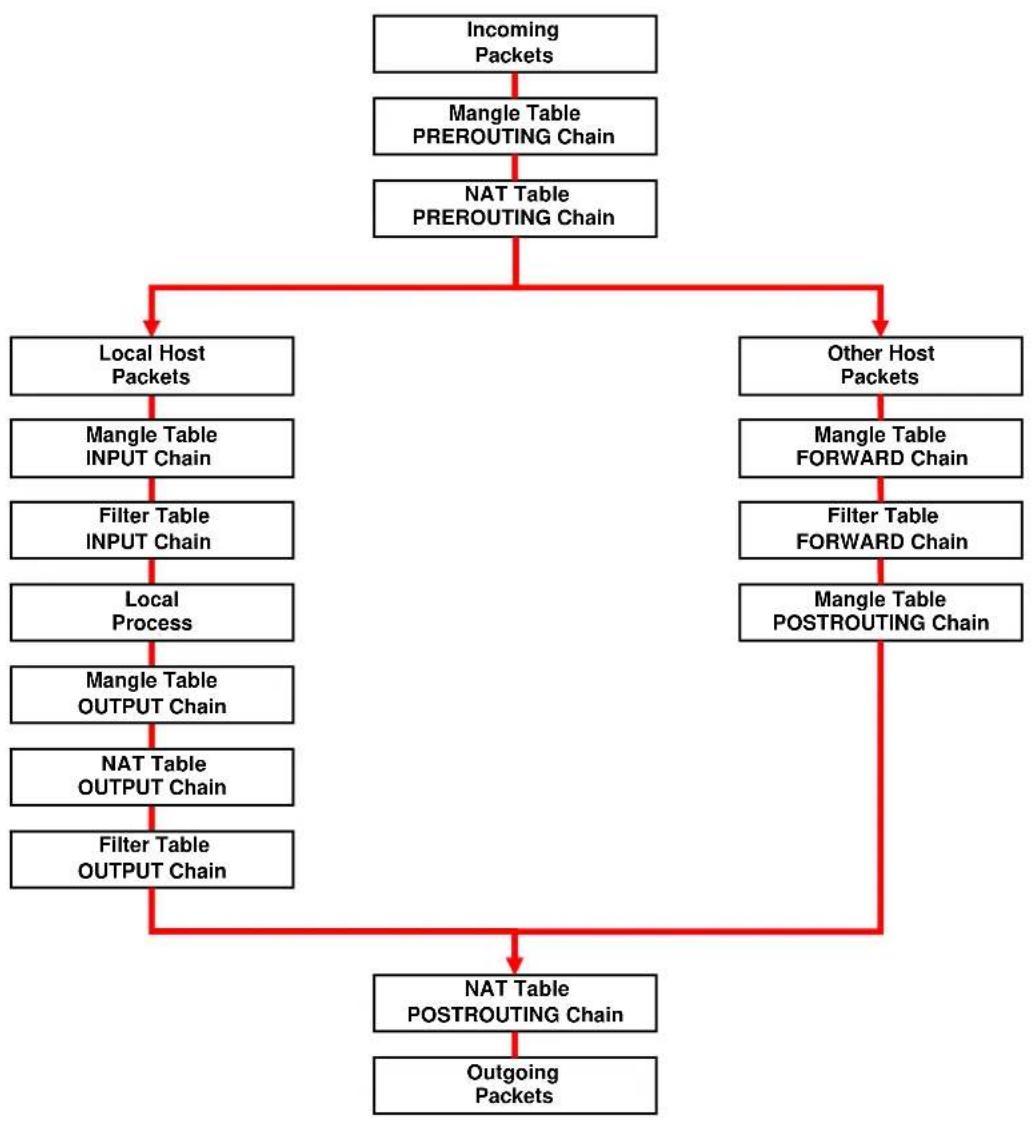
flowchart
graph TD
    A["Incoming Packets"] --> B["Mangle Table PREROUTING Chain"]
    B --> C["NAT Table PREROUTING Chain"]
    C --> D["Local Host Packets"]
    C --> E["Other Host Packets"]
    D --> F["Mangle Table INPUT Chain"]
    F --> G["Filter Table INPUT Chain"]
    G --> H["Local Process"]
    H --> I["Mangle Table OUTPUT Chain"]
    I --> J["NAT Table OUTPUT Chain"]
    J --> K["Filter Table OUTPUT Chain"]
    K --> L["NAT Table POSTROUTING Chain"]
    L --> M["Outgoing Packets"]
    E --> N["Mangle Table FORWARD Chain"]
    N --> O["Filter Table FORWARD Chain"]
    O --> P["Mangle Table POSTROUTING Chain"]
UC-7420/7410 supports the following sub-modules. Be sure to use the module that matches your application.
| ip_conntrack | ipt_MARK | ipt_ah | ipt_state |
| ip_conntrack_ftp | ipt_MASQUERADE | ipt_esp | ipt_tcpmss |
| ipt_conntrack_irc | ipt_MIRROT | ipt_length | ipt_tos |
| ip_nat_ftp | ipt_REDIRECT | ipt_limit | ipt_tt |
| ip_nat_irc | ipt_REJECT | ipt_mac | ipt_uncle |
| ip_nat_snmp_basic | ipt_TCPMSS | ipt_mark | |
| ip_queue | ipt_TOS | ipt_multiport | |
| ipt_LOG | ipt_ULOG | ipt_owner | |
NOTE UC-7420/7410 does NOT support IPV6 and ipchains.
The basic syntax to enable and load an IPTABLES module is as follows:
1smod
modprobe ip_tables
modprobe iptable_filter
Use lsmod to check if the ip_tables module has already been loaded in the UC-7420/7410. Use modprobe to insert and enable the module.
Use the following command to load the modules (iptable_filter, iptable_mangle, iptable_nat):
modprobe iptable_filter
NOTE IPTABLES plays the role of packet filtering or NAT. Take care when setting up the IPTABLES rules. If the rules are not correct, remote hosts that connect via a LAN or PPP may be denied access. We recommend using the Serial Console to set up the IPTABLES.
Click on the following links for more information about iptables.
http://www.linuxguruz.com/iptables/
http://www.netfilter.org/documentation/HOWTO//packet-filtering-HOWTO.html
Since the IPTABLES command is very complex, to illustrate the IPTABLES syntax we have divided our discussion of the various rules into three categories: Observe and erase chain rules, Define policy rules, and Append or delete rules.
Observe and erase chain rules
Usage:
# iptables [-t tables] [-L] [-n]
-t tables: Table to manipulate (default: 'filter'); example: nat or filter.
-L [chain]: List List all rules in selected chains. If no chain is selected, all chains are listed.
-n: Numeric output of addresses and ports.
# iptables [-t tables] [-FXZ]
-F: Flush the selected chain (all the chains in the table if none is listed).
-X: Delete the specified user-defined chain.
-Z: Set the packet and byte counters in all chains to zero.
Examples:
<h1 id="iptables-l-n">iptables -L -n</h1>
In this example, since we do not use the -t parameter, the system uses the default 'filter' table. Three chains are included: INPUT, OUTPUT, and FORWARD. INPUT chains are accepted automatically, and all connections are accepted without being filtered.
#iptables -F
#iptables -X
#iptables -Z
Define policy for chain rules
Usage:
# iptables [-t tables] [-P] [INPUT, OUTPUT, FORWARD, PREROUTING, OUTPUT, POSTROUTING] [ACCEPT, DROP]
-P: Set the policy for the chain to the given target.
INPUT: For packets coming into the UC-7420/7410.
OUTPUT: For locally-generated packets
FORWARD: For packets routed out through the UC-7420/7410.
PREROUTING: To alter packets as soon as they come in.
POSTROUTING: To alter packets as they are about to be sent out.
Examples:
iptables -P INPUT DROP
iptables -P OUTPUT ACCEPT
iptables -P FORWARD ACCEPT
iptables -t nat -P PREROUTING ACCEPT
iptables -t nat -P OUTPUT ACCEPT
iptables -t nat -P POSTROUTING ACCEPT
In this example, the policy accepts outgoing packets and denies incoming packets.
Append or delete rules:
Usage:
# iptables [-t table] [-AI] [INPUT, OUTPUT, FORWARD] [-io interface] [-p tcp, udp, icmp, all] [-s IP/network] [--sport ports] [-d IP/network] [--dport ports] -j [ACCEPT. DROP]
-A: Append one or more rules to the end of the selected chain.
-I: Insert one or more rules in the selected chain as the given rule number.
-i: Name of an interface via which a packet is going to be received.
-o: Name of an interface via which a packet is going to be sent.
-p: The protocol of the rule or of the packet to check.
-s: Source address (network name, host name, network IP address, or plain IP address).
--sport: Source port number.
-d: Destination address.
--dport:Destinationportnumber.
-j: Jump target. Specifies the target of the rules; i.e., how to handle matched packets. For example, ACCEPT the packet, DROP the packet, or LOG the packet.
Examples:
Example 1: Accept all packets from lo interface.
# iptables -A INPUT -i lo -j ACCEPT
Example 2: Accept TCP packets from 192.168.0.1.
# iptables -A INPUT -i ixp0 -p tcp -s 192.168.0.1 -j ACCEPT
Example 3: Accept TCP packets from Class C network 192.168.1.0/24.
# iptables -A INPUT -i ixp0 -p tcp -s 192.168.1.0/24 -j ACCEPT
Example 4: Drop TCP packets from 192.168.1.25.
# iptables -A INPUT -i ixp0 -p tcp -s 192.168.1.25 -j DROP
Example 5: Drop TCP packets addressed for port 21.
# iptables -A INPUT -i ixp0 -p tcp --dport 21 -j DROP
Example 6: Accept TCP packets from 192.168.0.24 to UC-7420/7410's port 137, 138, 139
# iptables -A INPUT -i ixp0 -p tcp -s 192.168.0.24 --dport 137:139 -j ACCEPT
Example 7: Log TCP packets that visit UC-7420/7410's port 25.
# iptables -A INPUT -i ixp0 -p tcp --dport 25 -j LOG
Example 8: Drop all packets from MAC address 01:02:03:04:05:06.
# iptables -A INPUT -i ixp0 -p all -m mac -mac-source 01:02:03:04:05:06 -j DROP
NOTE: In Example 8, remember to issue the command #modprobe ipt_mac first to load module ipt_mac.
NAT
NAT (Network Address Translation) protocol translates IP addresses used on one network different IP addresses used on another network. One network is designated the inside network and the other is the outside network. Typically, UC-7420/7410 connects several devices on a network and maps local inside network addresses to one or more global outside IP addresses, and un-maps the global IP addresses on incoming packets back into local IP addresses.
NOTE Click on the following link for more information about iptables and NAT: http://www.netfilter.org/documentation/HOWTO/NAT-HOWTO.html
NAT Example
The IP address of all packets leaving LAN1 are changed to 192.168.3.127 (you will need to load the module ipt_MASQUERADE):
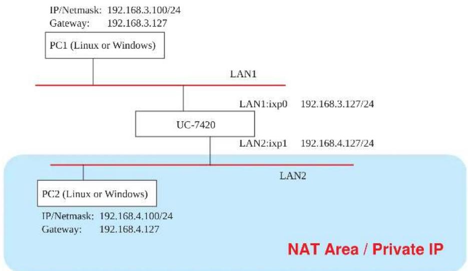
flowchart
graph TD
    A["PC1 (Linux or Windows)"] --> B["UC-7420"]
    B --> C["PC2 (Linux or Windows)"]
    A --> D["LAN1"]
    B --> E["LAN2"]
    C --> F["IP/Netmask: 192.168.3.100/24\nGateway: 192.168.3.127"]
    B --> G["LAN1:ixp0 192.168.3.127/24"]
    B --> H["LAN2:ixp1 192.168.4.127/24"]
    B --> I["LAN2"]
    style A fill:#f9f,stroke:#333
    style B fill:#ccf,stroke:#333
    style C fill:#cfc,stroke:#333
    style D fill:#fcc,stroke:#333
    style E fill:#fcc,stroke:#333
    style F fill:#fcc,stroke:#333
    style G fill:#fcc,stroke:#333
    style H fill:#fcc,stroke:#333
    style I fill:#fcc,stroke:#333
-
ehco 1 > /proc/sys/net/ipv4/ip_forward
-
modprobe iptable_nat
-
modprobe ip_conntract
-
modprobe ipt_MASQUERADE
-
iptables -t nat -A POSTROUTING -o ixp0 -j SNAT --to-source 192.168.3.127 or
-
iptables -t nat -A POSTROUTING -o ixp0 -j MASQUERADE
Enabling NAT at Bootup
In the most of real world situations, you will want to use a simple shell script to enable NAT when UC-7420/7410 boots up. The following script is an example.
#!/bin/bash
<h1 id="if-you-put-this-shell-script-in-the-homenatsh">If you put this shell script in the /home/nat.sh</h1>
<h1 id="remember-to-chmod-744-homenatsh">Remember to chmod 744 /home/nat.sh</h1>
<h1 id="edit-the-rclocal-file-to-make-this-shell-startup-automatically">Edit the rc.local file to make this shell startup automatically.</h1>
<h1 id="vi-etcrcdrclocal">vi /etc/rc.d/rc.local</h1>
<h1 id="add-a-line-in-the-end-of-rclocal-homenatsh">Add a line in the end of rc.local /home/nat.sh</h1>
EXIF='ixp0' #This is an external interface for setting up a valid IP address.
EXNET='192.168.4.0/24' #This is an internal network address.
<h1 id="step-1-insert-modules">Step 1. Insert modules.</h1>
<h1 id="here-2-devnull-means-the-standard-error-messages-will-be-dump-to-null-device">Here 2> /dev/null means the standard error messages will be dump to null device.</h1>
modprobe ip_tables 2> /dev/null
modprobe ip_nat_ftp 2> /dev/null
modprobe ip_nat_irc 2> /dev/null
modprobe ip_conntrack 2> /dev/null
modprobe ip_conntrack_ftp 2> /dev/null
modprobe ip_conntrack_irc 2> /dev/null
<h1 id="step-2-define-variables-enable-routing-and-erase-default-rules">Step 2. Define variables, enable routing and erase default rules.</h1>
PATH=/bin:/sbin:/usr/bin:/usr/sbin:/usr/local/bin:/usr/local/sbin
export PATH
echo "1" > /proc/sys/net/ipv4/ip_forward
/sbin/iptables -F
/sbin/iptables -X
/sbin/iptables -Z
/sbin/iptables -F -t nat
/sbin/iptables -X -t nat
/sbin/iptables -Z -t nat
/sbin/iptables -P INPUT ACCEPT
/sbin/iptables -P OUTPUT ACCEPT
/sbin/iptables -P FORWARD ACCEPT
/sbin/iptables -t nat -P PREROUTING ACCEPT
/sbin/iptables -t nat -P POSTROUTING ACCEPT
/sbin/iptables -t nat -P OUTPUT ACCEPT
<h1 id="step-3-enable-ip-masquerade">Step 3. Enable IP masquerade.</h1>
Dial-up Service—PPP
PPP (Point to Point Protocol) is used to run IP (Internet Protocol) and other network protocols over a serial link. PPP can be used for direct serial connections (using a null-modem cable) over a Telnet link, and links established using a modem over a telephone line.
Modem / PPP access is almost identical to connecting directly to a network through UC-7420/7410's Ethernet port. Since PPP is a peer-to-peer system, UC-7420/7410 can also use PPP to link two networks (or a local network to the Internet) to create a Wide Area Network (WAN).
NOTE Click on the following links for more information about ppp: http://tldp.org/HOWTO/PPP-HOWTO/index.html http://axion.physics.ubc.ca/ppp-linux.html
The pppd daemon is used to connect to a PPP server from a Linux system. For detailed information about pppd see the man page.
Example 1: Connecting to a PPP server over a simple dial-up connection
The following command is used to connect to a PPP server by modem. Use this command for old ppp servers that prompt for a login name (replace username with the correct name) and password (replace password with the correct password). Note that debug and defaultroute 192.1.1.17 are optional.
pppd connect 'chat -v " " ATDT5551212 CONNECT" " ogin: username word: password' /dev/ttyM0 115200 debug crtscts modem defaultroute
If the PPP server does not prompt for the username and password, the command should be entered as follows. Replace username with the correct username and replace password with the correct password.
pppd connect 'chat -v " " ATDT5551212 CONNECT" " ' user username password password /dev/ttyMO 115200 crtscts modem
The pppd options are described below:
connect 'chat etc...'
This option gives the command to contact the PPP server. The 'chat' program is used to dial a remote computer. The entire command is enclosed in single quotes because pppd expects a one-word argument for the 'connect' option. The options for 'chat' are given below:
-v
verbose mode; log what we do to syslog
" "
Double quotes—don't wait for a prompt, but instead do ... (note that you must include a space after the second quotation mark)
ATDT5551212
Dial the modem, and then ...
CONNECT
Wait for an answer.
" "
Send a return (null text followed by the usual return)
ogin: username word: password
Log in with username and password.
Refer to the chat man page, chat.8, for more information about the chat utility.
/dev/
Specify the callout serial port.
115200
The baud rate.
debug
Log status in syslog.
crtscts
Use hardware flow control between computer and modem (at 115200 this is a must).
modem
Indicates that this is a modem device; pppd will hang up the phone before and after making the call.
defaultroute
Once the PPP link is established, make it the default route; if you have a PPP link to the Internet, this is probably what you want.
192.1.1.17
This is a degenerate case of a general option of the form x.x.x.x:y.y.y.y. Here x.x.x.x is the local IP address and y.y.y.y is the IP address of the remote end of the PPP connection. If this option is not specified, or if just one side is specified, then x.x.x.x defaults to the IP address associated with the local machine's hostname (located in /etc/hosts), and y.y.y.y is determined by the remote machine.
Example 2: Connecting to a PPP server over a hard-wired link
If a username and password are not required, use the following command (note that noipdefault is optional):
pppd connect 'chat -v" " " " ' noipdefault /dev/ttyM0 19200 crtscts
If a username and password is required, use the following command (note that noipdefault is optional, and root is both the username and password):
pppd connect 'chat -v" " " " / user root password root noipdefault /dev/ttyM0 19200 crtscts
How to check the connection
Once you've set up a PPP connection, there are some steps you can take to test the connection. First, type:
/sbin/ifconfig
(The folder ifconfig may be located elsewhere, depending on your distribution.) You should be able to see all the network interfaces that are UP. ppp0 should be one of them, and you should recognize the first IP address as your own, and the "P-t-P address" (or point-to-point address) the address of your server. Here's what it looks like on one machine:
lo Link encap Local Loopback
inet addr 127.0.0.1 Bcast 127.255.255.255 Mask 255.0.0.0
UP LOOPBACK RUNNING MTU 2000 Metric 1
RX packets 0 errors 0 dropped 0 overrun 0
ppp0 Link encap Point-to-Point Protocol
inet addr 192.76.32.3 P-t-P 129.67.1.165 Mask 255.255.255.0
UP POINTOPOINT RUNNING MTU 1500 Metric 1
RX packets 33 errors 0 dropped 0 overrun 0
TX packets 42 errors 0 dropped 0 overrun 0
Now, type:
ping z.z.z.z
where z.z.z.z is the address of your name server. This should work. Here's what the response could look like:
waddington:\~\$p ping 129.67.1.165
PING 129.67.1.165 (129.67.1.165): 56 data bytes
64 bytes from 129.67.1.165: icmp_seq=0 ttl=225 time=268 ms
64 bytes from 129.67.1.165: icmp_seq=1 ttl=225 time=247 ms
64 bytes from 129.67.1.165: icmp_seq=2 ttl=225 time=266 ms
^C
--- 129.67.1.165 ping statistics ---
3 packets transmitted, 3 packets received, 0% packet loss
round-trip min/avg/max = 247/260/268 ms
waddington:\~\$
Try typing:
netstat -nr
This should show three routes, something like this:
Kernel routing table
| Destination | Gateway | Genmask | Flags | Metric | Ref | Use | |
| iface | |||||||
| 129.67.1.165 | 0.0.0.0 | 255.255.255.255 | UH | 0 | 0 | 6 | |
| ppp0 | |||||||
| 127.0.0.0 | 0.0.0.0 | 255.0.0.0 | U | 0 | 0 | 0 lo | |
| 0.0.0.0 | 129.67.1.165 | 0.0.0.0 | UG | 0 | 0 | 6298 | |
| ppp0 |
If your output looks similar but doesn't have the destination 0.0.0.0 line (which refers to the default route used for connections), you may have run pppd without the 'defaultroute' option. At this point you can try using Telnet, ftp, or finger, bearing in mind that you'll have to use numeric IP addresses unless you've set up /etc/resolv.conf correctly.
Setting up a Machine for Incoming PPP Connections
This first example applies to using a modem, and requiring authorization with a username and password.
pppd/dev/ttyM0 115200 crtscts modem 192.168.16.1:192.168.16.2 login auth
You should also add the following line to the file /etc/ppp/pap-secrets:
* * " " *
The first star (*) lets everyone login. The second star (*) lets every host connect. The pair of double quotation marks (``') is to use the file /etc/passwd to check the password. The last star (*) is to let any IP connect.
The following example does not check the username and password:
pppd/dev/ttyM0 115200 crtscts modem 192.168.16.1:192.168.16.2
PPPoE
How to use PPPoE on UC-7408:
- Update two files: /usr/sbin/pppd and /usr/lib/pppd/2.4.1/pppoe.so on the target UC-7408 for version V1.5 or earlier versions. Copy the files from the web or CD-ROM, and directly update it by the copy command or FTP.
- Connect UC-7408's LAN port to an ADSL modem with a cross-over cable, HUB, or switch.
- Login to the UC-7408 as the root user.
- Edit the file /etc/ppp/chap-secrets and add the following:
“username@hinet.net” * “password” *
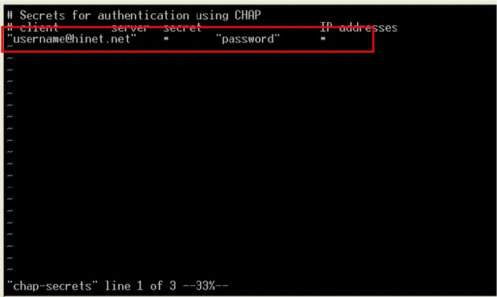
“username@hinet.net” is the username obtained from the ISP to log in to the ISP account. “password” is the corresponding password for the account.
- Edit the file /etc/ppp/pap-secrets and add the following:
"username@hinet.net" * "password" *
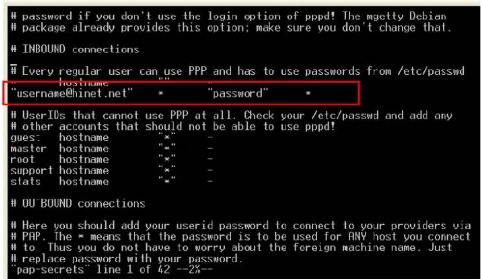
“username@hinet.net” is the username obtained from the ISP to log in to the ISP account. “password” is the corresponding password for the account.
- Edit the file /etc/ppp/options and add the following line:
plugin pppoe
<h1 id="terminated-because-it-was-idle">terminated because it was idle.</h1>
#holdoff <n>
<h1 id="wait-for-up-n-milliseconds-after-the-connect-script-finishes-for-a-valid">Wait for up n milliseconds after the connect script finishes for a valid</h1>
<h1 id="ppp-packet-from-the-peer-at-the-end-of-this-time-or-when-a-valid-ppp">PPP packet from the peer. At the end of this time, or when a valid PPP</h1>
<h1 id="packet-is-received-from-the-peer-pppd-will-commence-negotiation-by">packet is received from the peer, pppd will commence negotiation by</h1>
<h1 id="sending-its-first-lcp-packet-the-default-value-is-1000-1-second">sending its first LCP packet. The default value is 1000 (1 second).</h1>
<h1 id="this-wait-period-only-applies-if-the-connect-or-pty-option-is-used">This wait period only applies if the connect or pty option is used.</h1>
#connect delay <n>
plugin pppoe.so
<h1 id="end-of-file">---<End of File>---</h1>
"options" line 1 of 342 --0%--
- Add one of two files: /etc/ppp/options.ixp0 or /etc/ppp/options.ixp1. The choice depends on which LAN is connected to the ADSL modem. If you use LAN1 to connect to the ADSL modem, then add /etc/ppp/options.ixp0. If you use LAN2 to connect to the ADSL modem, then add /etc/ppp/options.ixp1. The file context is shown below:
name username@hinet.net
mtu 1492
mru 1492
defaultroute
noipdefault

"options.ixp0" line 1 of 5 --20%--
Type your username (the one you set in the /etc/ppp/pap-secrets and /etc/ppp/chap-secrets files) after the “name” option. You may add other options as desired.
- Set up DNS.
If you are using DNS servers supplied by your ISP, edit the file
/etc/resolv.conf by adding the following lines of code:
nameserver ip_addr_of_first_dns_server
nameserver ip_addr_of_second_dns_server
For example:
nameserver 168..95.1.1
nameserver 139.175.10.20
- Use the following command to create a pppoe connection:
pppd ixp0
The ixp0 is what is connected to the ADSL modem LAN port. The example above uses LAN1.
To use LAN2, type:
pppd ixp1
-
Type ifconfig ppp0 to check if the connection is OK or has failed. If the connection is OK, you will see information about the ppp0 setting for the IP address. Use ping to test the IP.
-
If you want to disconnect it, use the kill command to kill the pppd process.
NFS (Network File System)
The Network File System (NFS) is used to mount a disk partition on a remote machine, as if it were on a local hard drive, allowing fast, seamless sharing of files across a network. NFS allows users to develop applications for UC-7420/7410, without worrying about the amount of disk space that will be available. UC-7420/7410 supports NFS protocol for both client and server.
NOTE Click on the following links for more information about NFS: http://www.tldp.org/HOWTO/NFS-HOWTO/index.html http://nfs.sourceforge.net/nfs-howto/client.html http://nfs.sourceforge.net/nfs-howto/server.html
Setting up UC-7420/7410 as an NFS Server
By default, UC-7420/7410 enables the service /etc/init.d/nfs-user-server. The service link file S25nfs-user-server is located in the directory /rc.d/rc2.d-rc5.d.
Edit the NFS server configuration file /etc/exports to set up the remote host (NTF client) list and access rights for a specific directory. The file formats are shown below:
#vi /etc/exports
File Format:
directory machine1(option11,option12) machine2(option21,option22)
directory
The directory that will be shared with the NFS Client.
machine1 and machine2
Client machines that will have access to the directory. A machine can be listed by its DNS address or IP address (e.g., machine.company.com or 192.168.0.8).
optionxx
The option list for a machine describes the kind of access the machine will have. Important options are:
ro
Read only. This is the default.
rw
Readable and Writeable.
no\_root\_squash
If no_root_squash is selected, then the root on the client machine will have the same level of access to files on the system as the root on the server. This can have serious security implications, although it may be necessary if you want to do administrative work on the client machine that involves the exported directories. You should only specify this option when you have a good reason.
root\_squash
Any file request made by the user root on the client machine is treated as if it is made by user nobody on the server. (Exactly which UID the request is mapped to depends on the UID of user “nobody” on the server, not the client.)
sync
Sync data to memory and flash disk.
async
The async option instructs the server to lie to the client, telling the client that all data has been written to the stable storage.
Example 1
/tmp * (rw, no_root_squash)
In this example, UC-7420/7410 shares the /tmp directory to everyone, gives everyone both read and write authority. The root user on the client machine will have the same level of access to files on the system as the root on the server.
Example 2
/home/public 192.168.0.0/24(rw) *(ro)
In this example, UC-7420/7410 shares the directory /home/public to a local network
192.168.0.0/24, with read and write authority. NFS clients can just read /home/public; they do not have write authority.
Example 3
/home/test 192.168.3.100(rw)
In this example, UC-7420/7410 shares the directory /home/test to an NFS Client 192.168.3.100, with both read and write authority.
NOTE
After editing the NFS Server configuration file, remember to use the following command to restart and activate the NFS server.
/etc/init.d/nfs-user-server restart
Setting up UC-7420/7410 as an NFS Client
The following procedure is used to mount a remote NFS Server.
-
Scan the NFS Server's shared directory.
-
Establish a mount point on the NFS Client site.
-
Mount the remote directory to a local directory.
Step 1:
#showmount -e HOST
showmount: Show the mount information for an NFS Server.
-e: Show the NFS Server's export list.
HOST: IP address or DNS address.
Steps 2 & 3:
#mkdir -p /home/nfs/public
#mount -t nfs NFS_Server(IP) :/directory /mount/point
Example
: #mount -t nfs 192.168.3.100/home/public /home/nfs/public
smtpclient is a minimal SMTP client that takes an email message body and passes it on to an SMTP server. It is suitable for applications that use email to send alert messages or important logs to a specific user.
NOTE Click on the following link for more information about smtpclient:
http://www.engelschall.com/sw/smtpclient/
To send an email message, use the 'smtpclient' utility, which uses SMTP protocol. Type
smtpclient -help to see the help message.
Example:
smtpclient -s test -f sender@company.com -S IP_address receiver@company.com < mail-body-message
-s: The mail subject.
-f: Sender's mail address
-S: SMTP server IP address
The last mail address receiver@company.com is the receiver's e-mail address.
mail-body-message is the mail content. The last line of the body of the message should contain ONLY the period ‘.’ character.
You will need to add your hostname to the file /etc/hosts.
SNMP
UC-7420/7410 has built-in SNMP V1 (Simple Network Management Protocol) agent software. It supports RFC1317 RS-232 like group and RFC 1213 MIB-II.
The following simple example allows you to use an SNMP browser on the host site to query the UC-7420/7410, which is the SNMP agent. UC-7420/7410 will respond.
\*\*\*\*\* SNMP QUERY STARTED \*\*\*\*\*
1: sysDescr.0 (octet string) Linux Moxa 2.4.18_mvl30-ixdp425 #1049 Tue Oct 26 09:34:15 CST 2004 armv5teb
2: sysObjectID.0 (object identifier) enterprises.2021.250.10
3: sysUpTime.0 (timeticks) 0 days 00h:41m:54s.47th (251447)
4: sysContact.0 (octet string) Root root@localhost (configure /etc/snmp/snmp.local.conf)
5: sysName.0 (octet string) Moxa
6: sysLocation.0 (octet string) Unknown (configure /etc/snmp/snmp.local.conf)
7: system.8.0 (timeticks) 0 days 00h:00m:00s.22th (22)
8: system.9.1.2.1 (object identifier) mib-2.31
9: system.9.1.2.2 (object identifier) internet.6.3.1
10: system.9.1.2.3 (object identifier) mib-2.49
11: system.9.1.2.4 (object identifier) ip
12: system.9.1.2.5 (object identifier) mib-2.50
13: system.9.1.2.6 (object identifier) internet.6.3.16.2.2.1
14: system.9.1.2.7 (object identifier) internet.6.3.10.3.1.1
15: system.9.1.2.8 (object identifier) internet.6.3.11.3.1.1
16: system.9.1.2.9 (object identifier) internet.6.3.15.2.1.1
17: system.9.1.3.1 (octet string) The MIB module to describe generic objects for network interface sub-layers
18: system.9.1.3.2 (octet string) The MIB module for SNMPv2 entities
19: system.9.1.3.3 (octet string) The MIB module for managing TCP implementations
20: system.9.1.3.4 (octet string) The MIB module for managing IP and ICMP implementations
21: system.9.1.3.5 (octet string) The MIB module for managing UDP implementations
22: system.9.1.3.6 (octet string) View-based Access Control Model for SNMP.
23: system.9.1.3.7 (octet string) The SNMP Management Architecture MIB.
24: system.9.1.3.8 (octet string) The MIB for Message Processing and Dispatching.
25: system.9.1.3.9 (octet string) The management information definitions for the SNMP User-based Security Model.
26: system.9.1.4.1 (timeticks) 0 days 00h:00m:00s.04th (4)
27: system.9.1.4.2 (timeticks) 0 days 00h:00m:00s.09th (9)
28: system.9.1.4.3 (timeticks) 0 days 00h:00m:00s.09th (9)
29: system.9.1.4.4 (timeticks) 0 days 00h:00m:00s.09th (9)
30: system.9.1.4.5 (timeticks) 0 days 00h:00m:00s.09th (9)
31: system.9.1.4.6 (timeticks) 0 days 00h:00m:00s.19th (19)
32: system.9.1.4.7 (timeticks) 0 days 00h:00m:00s.22th (22)
33: system.9.1.4.8 (timeticks) 0 days 00h:00m:00s.22th (22)
34: system.9.1.4.9 (timeticks) 0 days 00h:00m:00s.22th (22)
***** SNMP QUERY FINISHED *****
NOTE
Click on the following links for more information about MIB II and RS-232 like group: http://www.faqs.org/rfcs/rfc1213.html http://www.faqs.org/rfc/rfc1317.html
→ UC-7420/7410 does NOT support SNMP trap.
The following tables list the variables supported by UC-7420/7410.
Open VPN
This function is only available for firmware version V1.5 (and later versions).
OpenVPN provides two types of tunnels for users to implement VPNS: Routed IP Tunnels and Bridged Ethernet Tunnels. Here we describe the second type of tunnel. To begin with, check to make sure that the system has a virtual device /dev/net/tun. If not, issue the following command:
# mknod /dev/net/tun c 10 200
An Ethernet bridge is used to connect different Ethernet networks together. The Ethernets are bundled into one bigger, "logical" Ethernet. Each Ethernet corresponds to one physical interface (or port) that is connected to the bridge.
On each OpenVPN machine, you should generate a working directory, such as /etc/openvpn, where script files and key files reside. Once established, all operations will be performed in that directory.
Setup 1: Ethernet Bridging for Private Networks on Different Subnets
- Set up four machines, as shown in the following diagram.
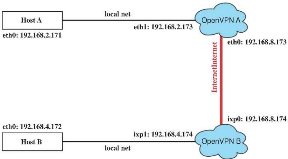
flowchart
graph TD
    A["Host A\neth0: 192.168.2.171"] -->|local net| B["OpenVPN A\neth1: 192.168.2.173"]
    B -->|Internet Internet| C["OpenVPN B\nixp0: 192.168.8.174"]
    D["Host B\neth0: 192.168.4.172"] -->|local net| E["OpenVPN B\nixp1: 192.168.4.174"]
Host A (B) represents one of the machines that belongs to OpenVPN A (B). The two remote subnets are configured for a different range of IP addresses. When this setup is moved to a public network, the external interfaces of the OpenVPN machines should be configured for static IPs, or connect to another device (such as a firewall or DSL box) first.
- Generate a preset shared key by typing the command:
# openvpn --genkey --secret secrouter.key
Copy the file that is generated to the OpenVPN machine.
- Generate a script file named openvpn-bridge on each OpenVPN machine. This script reconfigures interface "ixp1" as IP-less, creates logical bridge(s) and TAP interfaces, loads modules, enables IP forwarding, etc.
#----Start----
#!/bin/sh

iface=ixp1    # defines the internal interface
maxtap=`expr 1`    # defines the number of tap devices. I.e., # of tunnels

IPADDR=
NETMASK=
BROADCAST=

<h1 id="it-is-not-a-great-idea-but-this-system-doesnt-support">it is not a great idea but this system doesn't support</h1>
<h1 id="etcsysconfignetwork-scriptsifcfg-ixp1">/etc/sysconfig/network-scripts/ifcfg-ixp1</h1>
ifcfg_vpn()
{
    while read f1 f2 f3 f4 r3
    do
    if [ "f1" = "iface" -a "f2" = "iface" -a "f3" = "inet" -a "$f4" = "static" ]; then
    i=`expr 0`
    while :
    do
    if [ $i -gt 5 ]; then
    break
    fi
    i=`expr $i + 1`
    read f1 f2
    case "$f1" in
    address ) IPADDR=$f2
    ; ;
    netmask ) NETMASK=$f2
    ; ;
    broadcast ) BROADCAST=$f2
    ; ;
    esac
    done
    break
    fi
done < /etc/network/interfaces
}

<h1 id="get-the-ip-address-of-the-specified-interface">get the ip address of the specified interface</h1>
mname=
module_up()
{
    oIFS=$IFS
    IFS='
    '
    FOUND="no"
    for LINE in `lsmod`
    do
    TOK=`echo $LINE | cut -d' ` -f1`
    if [ "TOK" = "mname" ]; then
    FOUND="yes";
    break;
    fi
done
IFS=$oIFS if [ "$FOUND" = "no" ]; then modprobe $mname fi }
start() { ifcfg_vpn if [ ! -d "/dev/net" ]; then mkdir /dev/net fi
if [ ! -r "/dev/net/tun" ]; then
# create a device file if there is none
mknod /dev/net/tun c 10 200
fi

# load modules "tun" and "bridge"
mname=tun
module_up
mname=bridge
module_up
# create an ethernet bridge to connect tap devices, internal interface
brctl addbr br0
brctl addif br0 $iface
# the bridge receives data from any port and forwards it to other ports.

i=`expr 0`
while :
do
# generate a tap0 interface on tun
openvpn --mktun --dev tap${i}

# connect tap device to the bridge
brctl addif br0 tap${i}

# null ip address of tap device
ifconfig tap${i} 0.0.0.0 promisc up

i=`expr $i + 1`
if [ i -gemaxtap ]; then
break
fi
done
# null ip address of internal interface
ifconfig $iface 0.0.0.0 promisc up

# enable bridge ip
ifconfig br0 IPADDR netmaskNETMASK broadcast $BROADCAST

ipf=/proc/sys/net/ipv4/ip_forward
# enable IP forwarding
echo 1 > $ipf
echo "ip forwarding enabled to"
cat $ipf
}
stop() {
echo "shutdown openvpn bridge."
ifcfg_vpn
i=expr 0
while :
do
# disconnect tap device from the bridge
brctl delif br0 tap${i}
openvpn --rmtun --dev tap${i}

    i='expr $i + 1'
    if [ i -gemaxtap ]; then
    break
    fi
done
brctl delif br0 $iface
brctl delbr br0
ifconfig br0 down
ifconfig ifaceIPADDR netmask NETMASK broadcastBROADCAST
killall -TERM openvpn
}

case "$1" in
start)
    start
    ;;
stop)
    stop
    ;;
restart)
    stop
    start
    ;;
*)
echo "Usage: $0 [start|stop|restart]"
exit 1

esac
exit 0

#---- end ----
Create link symbols to enable this script at boot time:
<h1 id="ln-s-etcopenvpnopenvpn-bridge-etcrcdrc3ds32vpn-br-for-example">ln -s /etc/openvpn/openvpn-bridge /etc/rc.d/rc3.d/S32vpn-br # for example</h1>
<h1 id="ln-s-etcopenvpnopenvpn-bridge-etcrcdrc6dk32vpn-br-for-example">ln -s /etc/openvpn/openvpn-bridge /etc/rc.d/rc6.d/K32vpn-br # for example</h1>
- Create a configuration file named A-tap0-br.conf and an executable script file named A-tap0-br.sh on OpenVPN A.
<h1 id="point-to-the-peer">point to the peer</h1>
remote 192.168.8.174
dev tap0
secret /etc/openvpn/secrouter.key
cipher DES-EDE3-CBC
auth MD5
tun-mtu 1500
tun-mtu-extra 64
ping 40
up /etc/openvpn/A-tap0-br.sh

#----Start----
#!/bin/sh

<h1 id="value-after-net-is-the-subnet-behind-the-remote-peer">value after "-net" is the subnet behind the remote peer</h1>
route add -net 192.168.4.0 netmask 255.255.255.0 dev br0

#----end----
Create a configuration file named B-tap0-br.conf and an executable script file named B-tap0-br.sh on OpenVPN B.
<h1 id="point-to-the-peer-2">point to the peer</h1>
remote 192.168.8.173
dev tap0
secret /etc/openvpn/secrouter.key
cipher DES-EDE3-CBC
auth MD5
tun-mtu 1500
tun-mtu-extra 64
ping 40
up /etc/openvpn/B-tap0-br.sh
#---- Start----
#!/bin/sh
<h1 id="value-after-net-is-the-subnet-behind-the-remote-peer-2">value after "-net" is the subnet behind the remote peer</h1>
route add -net 192.168.2.0 netmask 255.255.255.0 dev br0
#---- end ----
Note: Select cipher and authentication algorithms by specifying “cipher” and “auth”. To see with algorithms are available, type:
<h1 id="openvpn-show-ciphers">openvpn --show-ciphers</h1>
<h1 id="openvpn-show-auths">openvpn --show-auths</h1>
- Start both of OpenVPN peers,
<h1 id="openvpn-config-a-tap0-brconf">openvpn --config A-tap0-br.conf&</h1>
<h1 id="openvpn-config-b-tap0-brconf">openvpn --config B-tap0-br.conf&</h1>
If you see the line “Peer Connection Initiated with 192.168.8.173:5000” on each machine, the connection between OpenVPN machines has been established successfully on UDP port 5000.
- On each OpenVPN machine, check the routing table by typing the command:
# route
| Destination | Gateway | Genmsk | Flags | Metric | Ref | Use | Iface |
| 192.168.4.0 | * | 255.255.255.0 | U | 0 | 0 | ||
| 192.168.2.0 | * | 255.255.255.0 | U | 0 | 0 | ||
| 192.168.8.0 | * | 255.255.255.0 | U | 0 | 0 |
Interface ixp1 is connected to the bridging interface br0, to which device tap0 also connects, whereas the virtual device tun sits on top of tap0. This ensures that all traffic from internal networks connected to interface ixp1 that come to this bridge write to the TAP/TUN device that the OpenVPN program monitors. Once the OpenVPN program detects traffic on the virtual device, it sends the traffic to its peer.
- To create an indirect connection to Host B from Host A, you need to add the following routing item:
route add -net 192.168.4.0 netmask 255.255.255.0 dev eth0
To create an indirect connection to Host A from Host B, you need to add the following routing item:
route add -net 192.168.2.0 netmask 255.255.255.0 dev eth0
Now ping Host B from Host A by typing:
ping 192.168.4.174
A successful ping indicates that you have created a VPN system that only allows authorized users from one internal network to access users at the remote site. For this system, all data is transmitted by UDP packets on port 5000 between OpenVPN peers.
- To shut down OpenVPN programs, type the command:
# killall -TERM openvpn
Setup 2: Ethernet Bridging for Private Networks on the Same Subnet
- Set up four machines as shown in the following diagram:
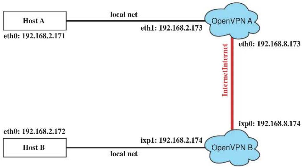
flowchart
graph TD
    A["Host A\neth0: 192.168.2.171"] -->|local net| B["OpenVPN A\neth1: 192.168.2.173"]
    B -->|InternetInternet| C["OpenVPN B\nixp0: 192.168.8.174"]
    D["Host B\neth0: 192.168.2.172"] -->|local net| E["OpenVPN B\nixp1: 192.168.2.174"]
- The configuration procedure is almost the same as for the previous example. The only difference is that you will need to comment out the parameter "up" in "/etc/openvpn/A-tap0-br.conf" and "/etc/openvpn/B-tap0-br.conf".
Setup 3: Routed IP
- Set up four machines as shown in the following diagram:
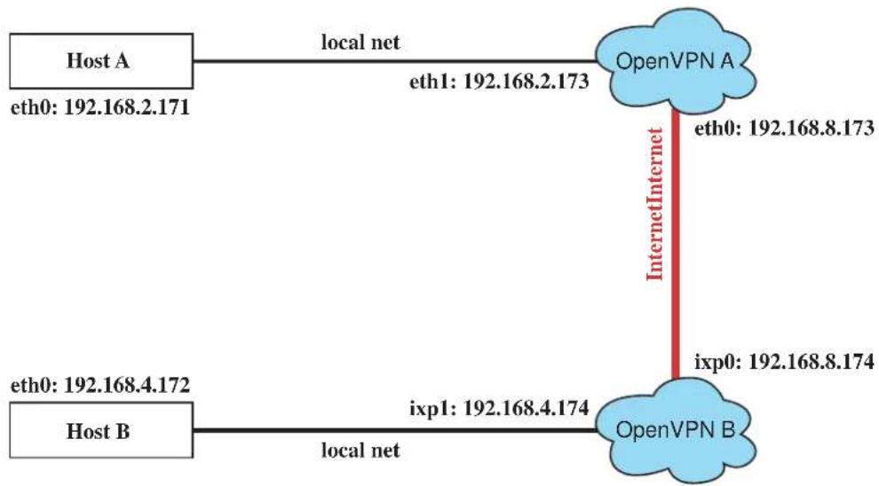
flowchart
graph TD
    A["Host A\neth0: 192.168.2.171"] -->|local net| B["OpenVPN A\neth1: 192.168.2.173"]
    B -->|InternetInternet| C["OpenVPN B\nixp0: 192.168.8.174"]
    D["Host B\neth0: 192.168.4.172"] -->|local net| E["OpenVPN B\nixp1: 192.168.4.174"]
- Create a configuration file named "A-tun.conf" and an executable script file named "A-tun.sh".
<h1 id="point-to-the-peer-3">point to the peer</h1>
remote 192.168.8.174
dev tun
secret /etc/openvpn/secrouter.key
cipher DES-EDE3-CBC
auth MD5
tun-mtu 1500
tun-mtu-extra 64
ping 40
ifconfig 192.168.2.173 192.168.4.174
up /etc/openvpn/A-tun.sh

#---- Start----
#!/bin/sh

<h1 id="value-after-net-is-the-subnet-behind-the-remote-peer-3">value after "-net" is the subnet behind the remote peer</h1>
route add -net 192.168.4.0 netmask 255.255.255.0 gw $5
#---- end ----
Create a configuration file named B-tun.conf and an executable script file named B-tun.sh on OpenVPN B:
remote 192.168.8.173
dev tun
secret /etc/openvpn/secrouter.key
cipher DES-EDE3-CBC
auth MD5
tun-mtu 1500
tun-mtu-extra 64
ping 40
ifconfig 192.168.4.174 192.168.2.173
up /etc/openvpn/B-tun.sh

#---- Start----
#!/bin/sh

<h1 id="value-after-net-is-the-subnet-behind-the-remote-peer-4">value after "-net" is the subnet behind the remote peer</h1>
route add -net 192.168.2.0 netmask 255.255.255.0 gw $5
#---- end
Note that the parameter “ifconfig” defines the first argument as the local internal interface and the second argument as the internal interface at the remote peer.
Note that \$5 is the argument that the OpenVPN program passes to the script file. Its value is the second argument of ifconfig in the configuration file.
- Check the routing table after you run the OpenVPN programs, by typing the command:
route
| Destination | Gateway | Genmsk | Flags | Metric | Ref | Use | |
| 192.168.4.174 | * | 255.255.255.255 | UH | 0 | 0 | 0 | |
| 192.168.4.0 | 192.168.4.174 | 255.255.255.0 | UG | 0 | 0 | 0 | |
| 192.168.2.0 | * | 255.255.255.0 | U | 0 | 0 | 0 | ixp1 |
| 192.168.8.0 | * | 255.255.255.0 | U | 0 | 0 | 0 | ixp0 |
Iface
tun0
tun0
This chapter includes important information for programmers.
This following functions are covered in this chapter:
□ Flash Memory Map
☐ Linux Tool Chain Introduction
□ Debugging with GDB
Device API
☐ RTC (Real Time Clock)
□ Buzzer
□ WDT (Watch Dog Timer)
□ UART
□ LCM
□ KeyPad
□ Make File Example
Flash Memory Map
Partition sizes are hard coded into the kernel binary. To change the partition sizes, you will need to rebuild the kernel. The flash memory map is shown in the following table.
| Address | Size | Contents |
| 0x00000000 - 0x0005FFFF 384 KB | Boot Loader | —Read ONLY |
| 0x00060000 - 0x0015FFFF 1 MB | Kernel object code | —Read ONLY |
| 0x00160000 - 0x0055FFFF 4 MB | Mini root file system (EXT2) | —Read ONLY |
| 0x00560000 - 0x01F5FFFF 26 MB | User root file system (JFFS2) | —Read/Write |
| 0x01F60000 - 0x01FBFFFF 384 KB | Not used | |
| 0x01FC0000 - 0x01FDFFFF 128 KB | Boot Loader configuration | —Read ONLY |
| 0x01FE0000 - 0x01FFFFFF 128 KB | Boot Loader directory | —Read ONLY |
Mount the user file system to /mnt/usrdisk with the root file system. Check to see if the user file system was mounted correctly. If user file system is okay, the kernel will change the root file system to /mnt/usrdisk. If the user file system is not okay, the kernel will use the default Moxa file system. To finish boot process, run the init program.
NOTE
- The default Moxa file system only enables the network and CF. It lets users recover the user file system when it fails.
- The user file system is a complete file system. Users can create and delete directories and files (including source code and executable files) as needed.
- Users can create the user file system on the PC host or target platform, and then copy it to the UC-7420/7410.
Linux Tool Chain Introduction
To ensure that an application will be able to run correctly when installed on UC-7420/7410, you must ensure that it is compiled and linked to the same libraries that will be present on the UC-7420/7410. This is particularly true when the RISC Xscale processor architecture of the UC-7420/7410 differs from the CISC x86 processor architecture of the host system, but it is also true if the processor architecture is the same.
The host tool chain that comes with UC-7420/7410 contains a suite of cross compilers and other tools, as well as the libraries and headers that are necessary to compile applications for UC-7420/7410. The host environment must be running Linux to install the UC-7420/7410 GNU Tool Chain. We have confirmed that the following Linux distributions can be used to install the tool chain:
Redhat 7.3/8.0/9.0, Fefora core 1 & 2.
The Tool Chain will need about 100 MB of hard disk space on your PC. The UC-7420/7410 Tool Chain is located on the UC-7420/7410 CD. To install the Tool Chain, insert the CD into your PC and then issue the following commands:
mount /dev/cdrom /mnt/cdrom
rpm -ivh /mnt/cdrom/mxscaleb-3.3.2-6.i386.rpm
Wait for a few minutes while the Tool Chain is installed automatically on your Linux PC. Once the host environment has been installed, add the directory /usr/local/mxscaleb/bin to your path and the directory /usr/local/mxscaleb/man to your manual path. You can do this temporarily for the current login session by issuing the following commands:
export PATH="/usr/local/mxscaleb/bin:\$PATH"
export MANPATH="/usr/local/mxscaleb/man:\$PATH"
Alternatively, you can add the same commands to \$HOME/.bash_profile to cause it to take effect for all login sessions initiated by this user.
Obtaining help
Use the Linux man utility to obtain help on many of the utilities provided by the tool chain. For example to get help on the armv5b-linux-gcc compiler, issue the command:
man armv5b-linux-gcc
Cross Compiling Applications and Libraries
To compile a simple C application, just use the cross compiler instead of the regular compiler:
#mxscaleb-gcc -o example -Wall -g -02 example.c
#mxscaleb-strip -s example
#mxscaleb-gcc -ggdb -o example-debug example.c
Tools Available in the Host Environment
Most of the cross compiler tools are the same as their native compiler counterparts, but with an additional prefix that specifies the target system. In the case of x86 environments, the prefix is i386-linux- and in the case of UC-7420/7410 Xscale boards, it is mxscaleb-.
For example the native C compiler is gcc and the cross C compiler for Xscale in UC-7420/7410 is mxscaleb-gcc.
The following cross compiler tools are provided:
| ar Manage archives (static libraries) | |
| as | Assembler |
| c++, g++ C++ compiler | |
| cpp | C preprocessor |
| gcc | C compiler |
| gdb | Debugger |
| ld | Linker |
| nm Lists symbols from object files | |
| objcopy Copies and translates object files | |
| objdump Displays information about object files | |
| ranlib Generates indexes to archives (static libraries) | |
| readelf Displays information about ELF files | |
| size Lists object file section sizes | |
| strings | Prints strings of printable characters from files (usually object files) |
| strip | Removes symbols and sections from object files (usually debugging information) |
Debugging with GDB
First compile the program must with option -ggdb. Use the following steps:
- To debug a program called hello-debug on the target, use the command:
gdbserver 192.168.4.142:2000 hello-debug
This is where 2000 is the network port number on which the server waits for a connection from the client. This can be any available port number on the target. Following this are the name of the program to be debugged (hello-debug), plus that program's arguments. Output similar to the following will be sent to the console:
Process hello-debug created; pid=38
-
Use the following command on the host to change to the directory that contains hello-debug: cd /my_work_directory/myfilesystem/testprograms
-
Enter the following command:
ddd --debugger mxscaleb-gdb hello-debug &
- Enter the following command at the GDB, DDD command prompt:
Target remote 192.168.4.99:2000
The command produces another line of output on the target console, similar to the following: Remote debugging using 192.168.4.99:2000
192.168.4.99 is the machine's IP address, and 2000 is the port number. You can now begin debugging in the host environment using the interface provided by DDD.
-
Set a breakpoint on main by double clicking, or entering b main on the command line.
-
Click the cont button
Device API
UC-7420/7410 supports control devices with the ioctl system API. You will need to include
int ioctl(int d, int request,...); Input: int d - open device node return file handle int request - argument in or out
Use the desktop Linux's man page for detailed documentation:
man ioctl
RTC (Real Time Clock)
The device node is located at /dev/rtc. UC-7420/7410 supports Linux standard simple RTC control. You must include
-
Function: RTC_RD_TIME int ioctl(fd, RTC_RD_TIME, struct rtc_time *time); Description: read time information from RTC. It will return the value on argument 3.
-
Function: RTC_SET_TIME int ioctl(fd, RTC_SET_TIME, struct rtc_time *time); Description: set RTC time. Argument 3 will be passed to RTC.
Buzzer
The device node is located at /dev/console. UC-7420/7410 supports Linux standard buzzer control, with UC-7420/7410's buzzer running at a fixed frequency of 100 Hz. You must include
1. Function: KDMKTONE
ioctl(fd, KDMKTONE, unsigned int arg);
Description: The buzzer's behavior is determined by the argument arg. The “high word” part of arg gives the length of time the buzzer will sound, and the “low word” part gives the frequency.
The buzzer's on / off behavior is controlled by software. If you call the "ioctl" function, you MUST set the frequency at 100Hz . If you use a different frequency, the system could crash.
WDT (Watch Dog Timer)
This function is only available for firmware version V1.5 (and later versions).
1. Introduction
The WDT works like a watch dog function. You can enable it or disable it. When the user enables WDT but the application does not acknowledge it, the system will reboot. You can set the ack time from a minimum of 50 msec to a maximum of 60 seconds.
2. How the WDT works
The sWatchDog is enabled when the system boots up. The kernel will auto ack it. The user application can also enable ack. When the user does not ack, it will let the system reboot.
Kernel boot
...
• + • •
User application running and enable user ack
• + • •
...
3. The user API
The user application must include
a11:
mxscaleb-gcc -o xxxx xxxx.c -lmoxalib
int swtd_open(void)
Description
Open the file handle to control the sWatchDog. If you want to do something you must first to this. And keep the file handle to do other.
Input
None
Output
The return value is file handle. If has some error, it will return < 0 value.
You can get error from errno().
int swtd_enable(int fd, unsigned long time)
Description
Enable application sWatchDog. And you must do ack after this process.
Input
int fd - the file handle, from the swtd_open() return value.
unsigned long time - The time you wish to ack sWatchDog periodically. You must ack the sWatchDog before timeout. If you do not ack, the system will be reboot automatically. The minimal time is 50 msec, the maximum time is 60 seconds. The time unit is msec.
Output
OK will be zero. The other has some error, to get the error code from errno().
int swtd_disable(int fd)
Description:
Disable the application to ack sWatchDog. And the kernel will be auto ack it. User does not to do it at periodic.
Input :
int fd - the file handle from swtd_open() return value.
Output:
OK will be zero. The other has some error, to get error code from errno.
int swtd_get(int fd, int *mode, unsigned long *time)
Description:
Get current setting values.
mode -
1 for user application enable sWatchDog: need to do ack.
0 for user application disable sWatchdog: does not need to do ack.
time - The time period to ack sWatchDog.
Input :
int fd - the file handle from swtd_open() return value.
int *mode - the function will be return the status enable or disable user application need to do ack.
unsigned long *time – the function will return the current time period.
Output:
OK will be zero.
The other has some error, to get error code from errno().
int swtd_ack(int fd)
Description:
Acknowledge sWatchDog. When the user application enable sWatchDog. It need to call this function periodically with user predefined time in the application program.
Input :
int fd - the file handle from swtd_open() return value.
Output:
OK will be zero.
The other has some error, to get error code from errno().
int swtd_close(int fd)
Description:
Close the file handle.
Input :
int fd - the file handle from swtd_open() return value.
Output:
OK will be zero.
The other has some error, to get error code from errno().
4. Special Note
When you “kill the application with -9” or “kill without option” or “Ctrl+c” the kernel will change to auto ack the sWatchDog.
When your application enables the sWatchDog and does not ack, your application may have a logical error, or your application has made a core dump. The kernel will not change to auto ack. This can cause a serious problem, causing your system to reboot again and again.
5. User application example
Example 1:
#include <stdio.h>
#include <stdlib.h>
#include <string.h>
#include <moxadevice.h>

int main(int argc, char *argv[])
{
    int fd;

    fd = swtd_open();
    if (fd < 0) {
    printf("Open sWatchDog device fail!\n");
    exit(1);
    }
    swtd_enable(fd, 5000); // enable it and set it 5 seconds
    while (1) {
    // do user application want to do
    ....
    ....
    swtd_ack(fd);
    ....
    ....
    }
}
swtd_close(fd);
exit(0);
}
The makefile is shown below:
all:
mxscaleb-gcc -o xxxx xxxx.c -lmoxalib
Example 2:
#include <stdio.h>
#include <stdlib.h>
#include <signal.h>
#include <string.h>
#include <sys/stat.h>
#include <sys/ioctl.h>
#include <sys/select.h>
#include <sys/time.h>
#include <moxadevice.h>

static void mydelay(unsigned long msec)
{
    struct timeval time;

    time.tv_sec = msec / 1000;
    time.tv_usec = (msec % 1000) * 1000;
    select(1, NULL, NULL, NULL, &time);
}

static int swtdfd;
static int stopflag=0;

static void stop_swatchdog()
{
    stopflag = 1;
}

static void do_swatchdog(void)
{
    swtd_enable(swtdfd, 500);
    while (stopflag == 0) {
    mydelay(250);
    swtd_ack(swtdfd);
    }
    swtd_disable(swtdfd);
}

int main(int argc, char *argv[])
{
    pid_t sonpid;

    signal(SIGUSR1, stop_swatchdog);
    swtdfd = swtd_open();
    if (swtdfd < 0) {
    printf("Open sWatchDog device fail!\n");
    exit(1);
    }
    if ((sonpid=fork()) == 0)
    do_swatchdog();
    // do user application main function
    ....
    ....
    ....
    // end user application
    kill(sonpid, SIGUSR1);
    swtd_close(swtdfd);
exit(1);
}
The makefile is shown below:
all:
mxscaleb-gcc -o xxxx xxxx.c -lmoxalib
UART
The normal tty device node is located at /dev/ttyM0 ... ttyM7, and the modem tty device node is located at /dev/cum0 ... cum7.
UC-7420/7410 supports Linux standard termios control. The Moxa UART Device API allows you to configure ttyM0 to ttyM7 as RS-232, RS-422, 4-wire RS-485, or 2-wire RS-485. UC-7420/7410 supports RS-232, RS-422, 2-wire RS-485, and 4-wire RS485.
You must include
#define RS232_MODE 0
#define RS485_2WIRE_MODE 1
#define RS422_MODE 2
#define RS485_4WIRE_MODE 3
- Function: MOXA_SET_OP_MODE
int ioctl(fd, MOXA_SET_OP_MODE, &mode)
Description
Set the interface mode. Argument 3 mode will pass to the UART device driver and change it.
- Function: MOXA_GET_OP_MODE
int ioctl(fd, MOXA_GET_OP_MODE, &mode)
Description
Get the interface mode. Argument 3 mode will return the interface mode.
There are two Moxa private ioctl commands for setting up special baud rates.
Function: MOXA_SET_SPECIAL_BAUD_RATE
Function: MOXA_GET_SPECIAL_BAUD_RATE
If you use this ioctl to set a special baud rate, the termios cflag will be B4000000, in which case the B4000000 define will be different. If the baud rate you get from termios (or from calling tcgetattr()) is B4000000, you must call ioctl with MOXA_GET_SPECIAL_BAUD_RATE to get the actual baud rate.
Example to set the baud rate
#include <moxadevice.h>
#include <termios.h>
struct termios term;
int fd, speed;
fd = open("/dev/ttyM0", O_RDWR);
tcgetattr(fd, &term);
term.c_cflag &= ~(CBAUD | CBAUDEX);
term.c_cflag |= B4000000;
tcsetattr(fd, TCSANOW, &term);
speed = 500000;
ioctl(fd, MOXA_SET_SPECIAL_BAUD_RATE, &speed);
Example to get the baud rate
#include <moxadevice.h>
#include <termios.h>
struct termios term;
int fd, speed;
fd = open("/dev/ttyM0", O_RDWR);
tcgetattr(fd, &term);
if ((term.c_cflag & (CBAUD|CBAUDEX)) != B4000000) {
    // follow the standard termios baud rate define
} else {
    ioctl(fd, MOXA_GET_SPECIAL_BAUD_RATE, &speed);
}
Baud rate inaccuracy
Divisor = 921600/Target Baud Rate. (Only Integer part)
ENUM = 8 * (921600/Target - Divisor) (Round up or down)
Inaccuracy = ((Target Baud Rate - 921600/(Divisor + (ENUM/8))) / Target Baud Rate) * 100%
E.g.,
To calculate 500000 bps
Divisor = 1, ENUM = 7,
Inaccuracy = 1.7%
*The Inaccuracy should less than 2% for work reliably.
Special Note
- If the target baud rate is not a special baudrate (e.g. 50, 75, 110, 134, 150, 200, 300, 600, 1200, 1800, 2400, 4800, 9600, 19200, 38400, 57600, 115200, 230400, 460800, 921600), the termios cflag will be set to the same flag.
- If you use stty to get the serial information, you will get speed equal to 0.
LCM
UC-7420/7410 only supports text mode display, with screen size of 16 cols by 8 rows. The device node is /dev/1cm. See the examples given below. We provide a private struct defined as follows:
typedef struct lcm_xy {
    int x; // col value, the arrange is 0 - 15
    int y; // raw value, the arrange is 0 - 7
} lcm_xy_t;
Examples
int ioctl(fd, IOCTL_LCM_GOTO_XY, lcm_xy_t *pos);
Move the cursor position to x(col), y(raw) position. The argument 3 is the new position value.
int ioctl(fd, IOCTL_LCM_CLS, NULL);
Clears the LCM display.
int ioctl(fd, IOCTL_LCM_CLEAN_LINE, NULL);
To change one line to all spaces in the current row, and move the cursor to the 0 column of this row.
int ioctl(fd, IOCTL_LCM_GET_XY, lcm_xy_t *pos);
Get the current cursor position. The value will be returned in argument 3.
int ioctl(fd, IOCTL_LCM_BACK_LIGH_ON, NULL);
Turns the LCM back light on.
int ioctl(fd, IOCTL_LCM_BACK_LIGHT_OFF, NULL);
Turns the LCM back light off.
KeyPad
The device node is /dev/keypad. The key value is defined in moxadevice.h.
int ioctl(fd, IOCTL KEYPAD HAS PRESS, int *flag);
Checks how many keys have been pressed. Argument 3 returns the number of pressed keys. 0 means no keys were pressed.
int ioctl(fd, IOCTL KEYPAD_GET_KEY, int *key);
Gets the value of the last key that was pressed. This functions only reads one key value for each function call. The value of the key value is returned in argument 3.
Special Note
-
UC-7420/7410's kernel will store the "pressed key history" in a buffer. The maximum buffer size is 31 keys. If the buffer overflows, the first key of the 31 that was pressed will be dropped, without sounding the buzzer.
-
Currently, UC-7420/7410 does NOT support pressing more than 1 key at the same time.
Make File Example
The following Makefile file example codes are copied from the Hello example on UC-7420/7410's CD-ROM.
CC = /usr/local/mxscaleb/mxscaleb-gcc
CPP = /usr/local/mxscaleb/mxscaleb-gcc
SOURCES = hello.c
OBJS = $(SOURCES: .c=.o)
all: hello
hello: $(OBJS)
(CC) -o@ ^(LDFLAGS) $(LIBS)
clean:
rm -f $(OBJS) hello core *.gdb
Linux normal command utility collection
File manager
- cp
c o p y f i l e - ls
list file - ln
make symbolic link file - mount
mount and check file system - rm
delete file - chmod
change file owner & group & user - chown
c h a n g e f i l e o w n e r - chgrp
c h a n g e f i l e g r o u p - sync
sync file system, let system file buffer be saved to hardware - mv
move file - pwd
display now file directly - df
list now file system space - mkdir
make new directory - rmdir
delete directory
Editor
- vi
text editor - cat
dump file context - zcat
compress or expand files - grep
s e a r c h s t r i n g o n f i l e - cut
g e t s t r i n g o n f i l e - find
find file where are there - more
dump file by one page - test
test file exist or not - sleep
sleep (seconds) - echo
echo string
Network
- ping
ping to test network - route
routing table manager - netstat
display network status - ifconfig
set network ip address - tftp
- telnet
- ftp
Process
- kill
kill process
- ps
display now running process
Other
- dmesg
dump kernel log message
- sty
t o set serial port
- zcat
dump .gz file context
- mknod
make device node
- free
display system memory usage
- date
print or set the system date and time
- env
run a program in a modified environment
- clear
clear the terminal screen
- reboot
reboot / power off/on the server
- halt
halt the server
- du
estimate file space usage
- gzip, gunzip
compress or expand files
- hostname
show system's host name
Moxa special utilities
- kversion
show kernel version
- cat /etc/version
show user directory version
- upramdisk
mount ramdisk
- downramdisk
unmount ramdisk
- UC-7420/7410 User's Manual
- Copyright Notice
- Trademarks
- Disclaimer
- Technical Support Contact Information www.moxa.com/support
- Chapter 1 Introduction....1-1
- Chapter 2 Getting Started....2-1
- Chapter 3 Managing Embedded Linux ....3-1
- Chapter 4 Managing Communications....4-1
- Chapter 5 Programmer's Guide....5-1
- Appendix A System Commands....A-1
- Overview
- Hardware Introduction
- □ Placement Options
- □ Hardware Connection Description
- □ Software Introduction
- Package Checklist
- UC-7410-LX
- UC-7420-LX
- Product Features
- Appearance and Dimensions
- Appearance
- Hardware Block Diagram
- LED Indicators
- Reset-type Buttons
- Reset Button
- Reset to default Button
- ATTENTION
- Reset to default preserves user's data
- "Reset to Default" supported by hardware versions V1.2 and higher
- Real Time Clock
- WARNING
- Placement Options
- Wall or Cabinet
- DIN-Rail Mounting
- Hardware Connection Description
- Wiring Requirements
- Safety First!
- Wiring Caution!
- Temperature Caution!
- Connecting the Power
- Grounding UC-7420/7410
- Connecting to the Network
- Connecting to a Serial Device
- Connecting to the Console Port
- PCMCIA
- CompactFlash
- Software Introduction
- Software Architecture
- Journaling Flash File System (JFFS2)
- Powering on UC-7420/7410
- NOTE
- Connecting UC-7420/7410 to a PC
- Serial Console
- Telnet Console
- Serial Console Reminder
- Telnet Reminder
- SSH Console
- Windows Users
- Linux Users
- ssh 192.168.3.127
- Configuring the Ethernet Interface
- Modifying Network Settings with the Serial Console
- Static IP addresses:
- See the interfaces(5) manpage for information on what options are
- available.
- We always want the loopback interface.
- An example ethernet card setup: (broadcast and gateway are optional)
- Dynamic IP addresses:
- /etc/init.d/networking restart
- Modifying Network Settings over the Network
- Configuring the WLAN via the PCMCIA Interface
- IEEE802.11b
- vi /etc/pcmcia/network.opts
- Use DHCP (via /sbin/dhcpcd, /sbin/dhclient, or /sbin/pump)? [y/n]
- If you need to explicitly specify a hostname for DHCP requests
- Web's IF address, netmask, network address, broadcast address
- Gateway address for static routing wlan-ng.conf
- vi /etc/wlan/wlan.conf
- /etc/wlancfg/wlancfg-DEFAULT are used.
- for example:
- SSID_vlan0="linux-vlan"
- This expects a file called "/etc/wlan/wlancfg-linux-vlan" to be present.
- Use a SSID of "" to associate with any network in range.
- cp /etc/wlan/wlancfg-DEFAULT /etc/wlan/wlancfg-any
- vi /etc/wlan/wlancfg-any
- If PRIV_GENSTR is not empty, use PRIV_GENSTR to generate
- keys (just a convenience)
- or set them explicitly. Set genstr or keys, not both.
- IEEE802.11g
- embedded ethernet LAN1
- embedded ethernet LAN2
- 802.11g Gigabyte Cardbus wireless card
- Test Program—Developing Hello.c
- Installing the Tool Chain (Linux)
- mount /dev/cdrom /mnt/cdrom
- rpm -ivh /mnt/cdrom/mxscaleb-3.3.2-6.i386.rpm
- Checking the Flash Memory Space
- Compiling Hello.c
- Uploading "Hello" to UC-7420/7410 and Running the Program
- Developing Your First Application
- Testing Environment
- Compiling tcps2.c
- Uploading tcps2-release and Running the Program
- jobs // use this command to check if the program is running
- ps -ef // use this command to check if the program is running
- Testing Procedure Summary
- System Version Information
- kversion
- System Image Backup
- Upgrading the Firmware
- Upgrading the firmware will erase all data on the Flash ROM
- upfirm uc7400-x.x.x.frm
- Loading Factory Defaults
- Enabling and Disabling Daemons
- cd /etc/rc.d
- vi rc.local
- Setting the Run-Level
- cd /etc/rc.d/init.d
- Adjusting the System Time
- Setting the Time Manually
- date MMDDhhmmYYYY
- NTP Client
- Updating the Time Automatically
- Example shell script to update the system time periodically
- How to run the shell script automatically when the kernel boots up
- Cron—daemon to Execute Scheduled Commands
- Connecting Peripherals
- USB Mass Storage
- CF Mass Storage
- Telnet / FTP
- Enabling the Telnet/ftp server
- Disabling the Telnet/ftp server
- DNS
- /etc/hosts
- /etc/resolv.conf
- resolv.conf This file is the resolver configuration file
- See resolver(5).
- Web Service—Apache
- Saving a Web Page to the CF Card
- Step 1:
- Step 2:
- cd /etc/apache
- vi httpd.conf
- Step 3:
- cd /etc/init.d
- Step4:
- HTML4 Test Suite
- Contents
- IPTABLES
- Mangle Table—includes two chains
- 1smod
- modprobe ip_tables
- modprobe iptable_filter
- Observe and erase chain rules
- Usage:
- Examples:
- Define policy for chain rules
- iptables -P INPUT DROP
- iptables -P OUTPUT ACCEPT
- iptables -P FORWARD ACCEPT
- iptables -t nat -P PREROUTING ACCEPT
- iptables -t nat -P OUTPUT ACCEPT
- iptables -t nat -P POSTROUTING ACCEPT
- Append or delete rules:
- NAT
- NAT Example
- ehco 1 > /proc/sys/net/ipv4/ip_forward
- modprobe iptable_nat
- modprobe ip_conntract
- modprobe ipt_MASQUERADE
- iptables -t nat -A POSTROUTING -o ixp0 -j SNAT --to-source 192.168.3.127 or
- iptables -t nat -A POSTROUTING -o ixp0 -j MASQUERADE
- Enabling NAT at Bootup
- Dial-up Service—PPP
- Example 1: Connecting to a PPP server over a simple dial-up connection
- pppd connect 'chat -v " " ATDT5551212 CONNECT" " ogin: username word: password' /dev/ttyM0 115200 debug crtscts modem defaultroute
- pppd connect 'chat -v " " ATDT5551212 CONNECT" " ' user username password password /dev/ttyMO 115200 crtscts modem
- Example 2: Connecting to a PPP server over a hard-wired link
- pppd connect 'chat -v" " " " ' noipdefault /dev/ttyM0 19200 crtscts
- pppd connect 'chat -v" " " " / user root password root noipdefault /dev/ttyM0 19200 crtscts
- How to check the connection
- Setting up a Machine for Incoming PPP Connections
- PPPoE
- Secrets for authentication using CHAP
- client -- server secret -- IP addresses
- password if you don't use the login option of pppd! The mgetty Debian
- package already provides this option; make sure you don't change that.
- INBOUND connections
- Every regular user can use PPP and has to use passwords from /etc/passwd
- UserIDs that cannot use PPP at all. Check your /etc/passwd and add any
- other accounts that should not be able to use pppd!
- OUTBOUND connections
- Here you should add your userid password to connect to your providers via
- The * means that the password is to be used for ANY host you connect
- to. Thus you do not have to worry about the foreign machine name. Just
- replace password with your password.
- NFS (Network File System)
- Setting up UC-7420/7410 as an NFS Server
- #vi /etc/exports
- directory machine1(option11,option12) machine2(option21,option22)
- directory
- machine1 and machine2
- optionxx
- no\_root\_squash
- root\_squash
- Example 1
- Example 2
- Example 3
- Setting up UC-7420/7410 as an NFS Client
- Steps 2 & 3:
- Example
- smtpclient -help to see the help message.
- Example:
- SNMP
- \*\*\*\*\* SNMP QUERY STARTED \*\*\*\*\*
- Open VPN
- Setup 1: Ethernet Bridging for Private Networks on Different Subnets
- Setup 2: Ethernet Bridging for Private Networks on the Same Subnet
- Setup 3: Routed IP
- route
- Flash Memory Map
- Linux Tool Chain Introduction
- export PATH="/usr/local/mxscaleb/bin:\$PATH"
- export MANPATH="/usr/local/mxscaleb/man:\$PATH"
- Obtaining help
- man armv5b-linux-gcc
- Cross Compiling Applications and Libraries
- Tools Available in the Host Environment
- Debugging with GDB
- gdbserver 192.168.4.142:2000 hello-debug
- ddd --debugger mxscaleb-gdb hello-debug &
- Device API
- man ioctl
- RTC (Real Time Clock)
- Buzzer
- Function: KDMKTONE
- WDT (Watch Dog Timer)
- Introduction
- How the WDT works
- The user API
- Description
- Input
- Output
- Description:
- Input :
- Output:
- Special Note
- User application example
- UART
- Special Note
- LCM
- KeyPad
- Make File Example
- Linux normal command utility collection
- File manager
- Editor
- Network
- Process
- Other
- Moxa special utilities
Brand : Moxa
Model : UC-7420
Category : Thin client