UC-7112 - Thin client Moxa - Free user manual and instructions
Find the device manual for free UC-7112 Moxa in PDF.


| Product Type | Thin Client / Embedded Computer |
| Brand | Moxa |
| Model | UC-7112 |
| Processor | ARM9 32-bit RISC CPU, 200 MHz |
| RAM | 128 MB SDRAM |
| Storage | 32 MB Flash (expandable via SD or USB) |
| Operating System | Linux 2.6 or Windows CE |
| Ethernet Ports | 2 x 10/100BaseT(X) RJ45 |
| Serial Ports | 1 x RS-232 (DB9), 1 x RS-422/485 (DB9), 1 x RS-232/422/485 (Terminal Block) |
| USB Ports | 2 x USB 2.0 Host |
| Power Supply | 12 to 48 VDC (terminal block) |
| Power Consumption | 12 W max |
| Dimensions | 115 x 95 x 30 mm (4.5 x 3.7 x 1.2 in) |
| Weight | 300 g (0.66 lb) |
| Mounting | DIN-rail or wall mount |
| Operating Temperature | -10 to 60°C (14 to 140°F) |
| Certifications | CE, FCC, UL, EN 60950-1 |
| Main Functions | Remote desktop client, data logging, protocol conversion, web server |
| Cleaning | Wipe with a dry cloth; avoid liquids |
| Safety | Use only specified power supply; keep away from water |
| Spare Parts / Repairability | Contact Moxa support for replacement parts; not user-serviceable |
| General Information | Manual available in PDF (18 pages, EN) |
Frequently Asked Questions - UC-7112 Moxa
User questions about UC-7112 Moxa
0 question about this device. Answer the ones you know or ask your own.
Ask a new question about this device
Download the instructions for your Thin client in PDF format for free! Find your manual UC-7112 - Moxa and take your electronic device back in hand. On this page are published all the documents necessary for the use of your device. UC-7112 by Moxa.
USER MANUAL UC-7112 Moxa
Hardware User's Manual
Fifth Edition, June 2009
www.moxa.com/product
MOXA®
© 2009 Moxa Inc. All rights reserved. Reproduction without permission is prohibited.
UC-7112 LX Plus, UC-7112, UC-7110 Hardware User's Manual
The software described in this manual is furnished under a license agreement and may be used only in accordance with the terms of that agreement.
Copyright Notice
Copyright © 2009 Moxa Inc.
All rights reserved.
Reproduction without permission is prohibited.
Trademarks
MOXA is a registered trademark of Moxa Inc.
All other trademarks or registered marks in this manual belong to their respective manufacturers.
Disclaimer
Information in this document is subject to change without notice and does not represent a commitment on the part of Moxa.
Moxa provides this document “as is,” without warranty of any kind, either expressed or implied, including, but not limited to, its particular purpose. Moxa reserves the right to make improvements and/or changes to this manual, or to the products and/or the programs described in this manual, at any time.
Information provided in this manual is intended to be accurate and reliable. However, Moxa assumes no responsibility for its use, or for any infringements on the rights of third parties that may result from its use.
This product might include unintentional technical or typographical errors. Changes are made periodically to the information in this manual to correct such errors, and these changes are incorporated into new editions of the publication.
Technical Support Contact Information www.moxa.com/support
Moxa Americas:
Toll-free: 1-888-669-2872
Tel: +1-714-528-6777
Fax: +1-714-528-6778
Moxa China (Shanghai office):
Toll-free: 800-820-5036
Tel: +86-21-5258-9955
Fax: +86-10-6872-3958
Moxa Europe:
Tel: +49-89-3 70 03 99-0
Fax: +49-89-3 70 03 99-99
Moxa Asia-Pacific:
Chapter 1 Introduction....1-1
Overview....1-2
Package Checklist....1-2
Product Features 1-3
Product Specifications 1-4
Hardware Specifications 1-4
Software Specifications—μClinux (UC-7110 and UC-7112) 1-5
Software Specifications—Linux (UC-7112 Plus) 1-6
Hardware Block Diagram 1-6
Chapter 2 Hardware Introduction....2-1
Appearance 2-2
Dimensions 2-2
Panel Views....2-3
LED Indicators....2-3
Internal SD Socket 2-4
Additional Functions.... 2-4
Reset Button 2-4
Real Time Clock.... 2-5
Chapter 3 Hardware Connection Description ....3-1
Wiring Requirements 3-2
Connecting the Power 3-2
Grounding the UC-71xx Embedded Computer 3-2
Connecting Data Transmission Cables 3-3
Connecting to the Network 3-3
Connecting to a Serial Device 3-4
Serial Console Port 3-4
The Moxa UC-71xx series of embedded computers (UC-7110, UC-7112, and UC-7112 Plus) are mini, RISC-based, box-type computers that feature dual 10/100 Mbps Ethernet ports, two RS-232/422/485 serial ports, and an ARM9 processor. The computers come with Linux pre-installed. In addition, the UC-7112 Plus and UC-7112 have an internal SD socket for storage expansion to offer high performance communication with unlimited storage in a super-compact, palm-size box. The UC-71xx series of embedded computers are the right solution for embedded applications that call for a small computer, but that can store large amounts of memory and provide good computing performance.
In this chapter, we cover the following topics:
Overview
Package Checklist
□ Product Features
□ Product Specifications
▶ Hardware Specifications
Software Specifications—μClinux (UC-7110 and UC-7112)
Software Specifications—Linux (UC-7112 Plus)
Hardware Block Diagram
Overview
The UC-71xx series of mini, RISC-based communication platforms are ideal for embedded applications. All three computers in the series (UC-7110, UC-7112, and UC-7112 Plus) come with 2 RS-232/422/485 serial ports and dual 10/100 Mbps Ethernet LAN ports to provide users with a versatile communication platform.
The UC-71xx series computers use the Moxa ART ARM9 192 MHz RISC CPU. Unlike the x86 CPU, which uses a CISC design, the ARM9's RISC design architecture and modern semiconductor technology provide these computers with a powerful computing engine and communication functions, but without generating too much heat. The built-in NOR Flash ROM (8 MB for UC-7110/7112, 16 MB for UC-7112 Plus) and SDRAM (16 MB for UC-7110/7112, 32 MB for UC-7112 Plus) give you plenty of storage capacity, and the SD socket provides greater flexibility for running various applications. The dual LAN ports built into the ARM9 allow the UC-71xx computers to be used as communication platforms for basic data acquisition and protocol conversion applications, and the two RS-232/422/485 serial ports allow you to connect a variety of serial devices.
The UC-7110 and UC-7112 come with the Clinux operating system pre-installed, and the UC-7112 Plus comes with the Linux operating system with MMU support pre-installed. Software written for desktop PCs is easily ported to the UC-71xx computers with a GNU cross compiler, so that you will not need to spend time modifying existing software code. The operating system, device drivers, and your own software can all be stored in the computers' Flash memory.
Package Checklist
The UC-71xx series currently includes four models:
Standard Operating Temperature Models (-10 to 60°C)
UC-7110-LX
Mini RISC-based Ready-to-Run Embedded Computer with 2 Serial Ports, Dual Ethernet, Clinux OS.
UC-7112-LX
Mini RISC-based Ready-to-Run Embedded Computer with 2 Serial Ports, Dual Ethernet, SD slot, Linux OS.
UC-7112-LX Plus
Mini RISC-based Ready-to-Run Embedded Computer with 2 Serial Ports, Dual Ethernet, SD slot, Linux OS.
Wide Operating Temperature Model (-40 to 75°C)
UC-7110-T-LX
Mini RISC-based Ready-to-Run Embedded Computer with 2 Serial Ports, Dual Ethernet, Clinux OS, Wide Temperature.
Each model is shipped with the following items:
• 1 UC-7110 or UC-7112 or UC-7112 Plus
- Quick Installation Guide
- Document & Software CD
- Ethernet Cable: RJ45 to RJ45 cross-over cable, 100 cm
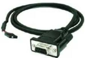
• CBL-4PINDB9F-100: 4-pin header to DB9 female console port cable, 100 cm
• Universal Power Adaptor
• Product Warranty Statement
Optional Accessories
• 35 mm DIN-Rail Mounting Kit (DK-35A)
NOTE: Please notify your sales representative if any of the above items are missing or damaged.
Product Features
The UC-71xx series computers have the following features:
• Moxa ART ARM9 32-bit 192 MHz processor
• 16 or 32 MB RAM (about 12 MB of user programmable space)
• 8 or 16 MB Flash ROM (about 4 MB of user programmable space)
- Dual 10/100 Mbps Ethernet for network redundancy
• 2 software-selectable RS-232/422/485 ports
- Serial port speed from 50 bps to 921.6 Kbps (non-standard baudrates supported)
• SD socket for storage expansion (UC-7112 and UC-7112 Plus only)
• Built-in RTC, Buzzer, WDT
• Built-in Linux Kernel 2.6 platform
- -40 to 75 °C wide operating temperature model available (UC-7110 only)
• DIN-Rail or wall mountable
- Robust fanless design
Product Specifications
Hardware Specifications
System
CPU Moxa ART ARM9 32-bit RISC CPU, 192 MHz
DRAM UC-7110: 16 MB
UC-7112: 16 MB
UC-7112 Plus: 32 MB
Flash UC-7110: 8 MB
UC-7112: 8 MB
UC-7112 Plus: 16 MB
Storage Expansion UC-7110: None
UC-7112: SD slot × 1
UC-7112 Plus: SD slot × 1
Console port RS-232 × 1 (TxD, RxD, GND), 4-pin header output, "115200, n, 8, 1"
Button Reset button × 1, supports “Reset to Factory Default”
Other RTC, buzzer, Watchdog Timer
OS UC-7110: Built-in μClinux, based on Linux Kernel 2.6
UC-7112: Built-in μClinux, based on Linux Kernel 2.6
UC-7112 Plus: Built-in Embedded Linux with MMU support, based on
Linux Kernel 2.6
Network Communication
LAN 10/100 Mbps RJ45 × 2, auto-
Protection 1.5 KV built-in magnetic isolation protection
Serial Communication
Serial Port Software-selectable RS-232/422/485, DB9 male × 2
Protection 15 KV built-in ESD protection for all signals
Data bits 5,6,7,8
Stop bit(s) 1, 1.5, 2
Parity None, Even, Odd, Space, Mark
Flow Control RTS/CTS, XON/XOFF, RS-485 ADDC™
Speed 50 bps to 921.6 Kbps; supporting, non-standard baudrates
LEDs
System Ready × 1
LAN 10 M/Link × 2, 100 M/Link × 2 (located on RJ45 connector)
Serial TxD× 2,RxD× 2
Power Requirements
Power Input 12 to 48 VDC
Power Consumption 340 mA @ 12 VDC, 4.5 W
Mechanical
Dimensions (W×D×H) 77 × 111 × 26 mm (3.03 × 4.37 × 1.02 in)
Weight
190
g
Construction Material aluminum, 1 mm
Mounting
DIN-rail,
Wall-mounting
Environment
Operating Temperature -10 to 60°C (14 to 140°F), 5 to 95% RH
-40 to 75°C (-40 to 167°F) for -T models
Storage Temperature -20 to 80°C (-4 to 176°F), 5 to 95% RH
-40 to 85°C (-40 to 185°F) for -T models
Anti-Vibration 1 g @ IEC-68-2-6, sine wave (resonance search), 5-500 Hz, 1 Oct/min, 1
cycle, 13 mins 17 sec per axis (UC-7110 only)
Regulatory Approvals
EMC FCC, CE (Class A)
FCC Part 15, CISPR 22 Class A
CE Class A: EN55022 Class A, EN61000-3-2 Class A,
EN61000-3-3, EN55024
Safety
TUV: IEC/EN60950
UL/cUL: UL60950, CAN/CSA-C22.2 No. 60950-00
Other
RoHS,
CRoHS,
WEEE
Warranty
5
years
Software Specifications—μClinux (UC-7110 and UC-7112)
Kernel Version: 2.6.19
Protocol Stacks: TCP, UDP, IPv4, SNMP V1, ICMP, ARP, HTTP, CHAP, PAP, DHCP, NTP, NFS, SMTP, Telnet, FTP, PPP, PPPoE
File System: JFFS2 (on-board flash) for Kernel, Root File System (Read Only) and User Directory (Read / Write)
System Utilities: msh, busybox, tinylogin, telnet, ftp
Supported Services and Daemons:
telnetd: Telnet Server daemon
ftpd: FTP server daemon
Boa: Web server daemon
pppd: dial in/out over serial port daemon & PPPoE
snmpd: snmpd agent daemon
inetd: TCP server manager program
Application Development Environment:
Moxa Linux API Library
Linux Tool Chain:
Arm-elf-gcc: C/C++ PC Cross Compiler
μClibc: POSIX Standard Library
Device Drivers:
UART, RTC, Buzzer, SD Card
Software Specifications—Linux (UC-7112 Plus)
Kernel Version: 2.6.9
Boot Loader: Redboot
Protocol Stacks: TCP, UDP, IPv4, SNMP V1, ICMP, IGMP, ARP, HTTP, CHAP, PAP, SSH 1.0/2.0, SSL, DHCP, NTP, NFS, SMTP, Telnet, FTP, PPP, PPPoE
File System: JFFS2 (on-board flash) for Kernel, Root File System (Read Only) and User Directory (Read / Write)
System Utilities: bash, busybox, tinylogin, telnet, ftp, scp
Supported Services and Daemons:
telnetd: Telnet Server daemon
ftpd: FTP server daemon
sshd: Secure shell server
Apache: Web server daemon, supports PHP and XML
OpenVPN: Virtual private network service manager
iptables: Firewall service manager
pppd: dial in/out over serial port daemon & PPPoE
snmpd: snmpd agent daemon
inetd: TCP server manager program
Application Development Environment:
Moxa Linux API Library
Linux Tool Chain: Gcc, Glibc, GDB
Device Drivers: Watchdog Timer (WDT), UART, RTC, Buzzer, SD Card
Hardware Block Diagram
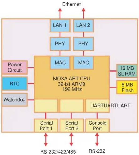
flowchart
graph TD
    A["Ethernet"] --> B["LAN 1"]
    A --> C["LAN 2"]
    B --> D["PHY"]
    C --> E["PHY"]
    D --> F["MAC"]
    E --> G["MAC"]
    H["Power Circuit"] --> I["MOXA ART CPU 32-bit ARM9 192 MHz"]
    J["RTC"] --> I
    K["Watchdog"] --> I
    I --> L["Serial Port 1"]
    I --> M["Serial Port 2"]
    I --> N["Console Port"]
    O["16 MB SDRAM"] --> P["8 MB Flash"]
    Q["RS-232/422/485"] --> R["Serial Port 1"]
    S["RS-232"] --> T["Serial Port 2"]
    U["UARTUARTUART"] --> V["Serial Port 1"]
    U --> W["Serial Port 2"]
The UC-7110, UC-7112, and UC-7112 Plus are compact, rugged embedded computers designed for industrial applications. The LED indicators on the computers' outer casing help you monitor the performance of the computers, and assist in identifying trouble spots. The hardware platform is both reliable and stable, and allows you to devote the bulk of your attention to developing your own application. In this chapter, we cover the basic hardware of the UC-71xx series embedded computers.
In this chapter, we cover the following topics:
□ Appearance
Dimensions
Panel Views
□ LED Indicators
Internal SD Socket
□ Additional Functions
Reset Button
Real Time Clock
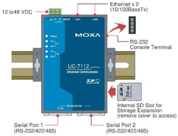
Appearance
The front view of the UC-7112 is shown in the following figure. The UC-7110 and UC-7112 Plus look the same, except that the UC-7110 does not have an internal SD slot.
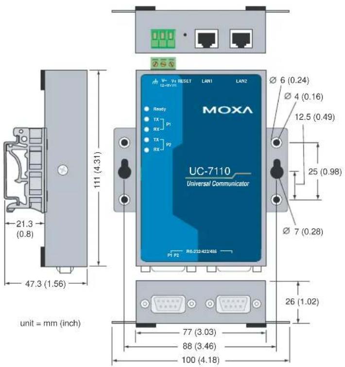
Dimensions
The dimensions of the UC-7110, UC-7112, and UC-7112 Plus are exactly the same.
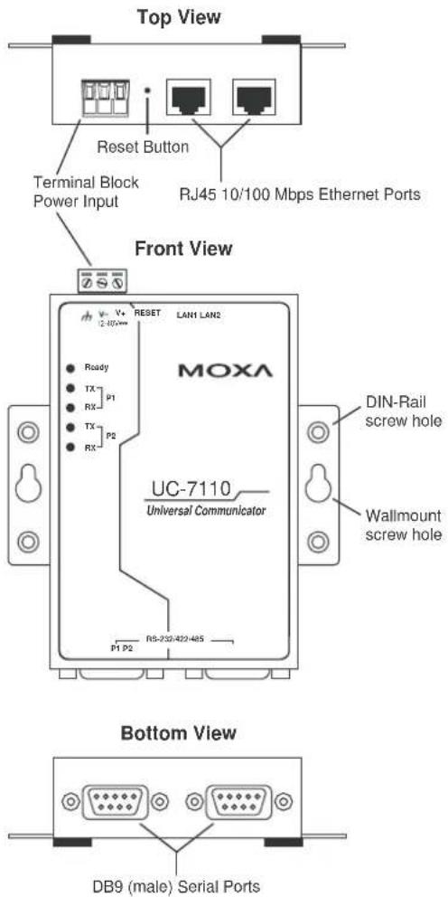
Panel Views
The three main panel views of the UC-7110, UC-7112, and UC-7112 Plus are shown below:
LED Indicators
The following table shows the functions of the five LED indicators located on the front panel of the UC-71xx embedded computers.
| LED Name LED | Color LED Function | |
| Ready Green Power | er is on and functioning normally. | |
| Green Serial port 1/2 is transmitting data. P1/P2 (Tx) | ||
| Off Serial port 1/2 is not transmitting data. | ||
| Yellow Serial port 1/2 is receiving data. P1/P2 (Rx) | ||
| Off Serial port 1/2 is not receiving data. | ||
Internal SD Socket
The UC-7112 and UC-7112 Plus have an internal SD socket for storage expansion. For the UC-7112, a Secure Digital (SD) memory card compliant with the SD 1.0 standard can be used to provide up to 1 GB of additional memory space. In addition, the UC-7112 Plus supports Secure Digital High Capacity (SDHC) memory cards that are compliant with the SD 2.0 standard, and can be used to provide up to 16 GB of additional memory space.
To install an SD card, first remove the outer cover of the embedded computer to access the SD slot. The internal SD slot is located on the back of the bottom board, in the slot on the right side of the UC-7112 and UC-7112 Plus, but lower than the cover screw. Plug the SD card directly into the socket and remember to “push in” the SD card first if you want to remove it.
Additional Functions
Reset Button
Press the “RESET” button continuously for more than 5 seconds to load the factory default configuration. After loading the factory defaults, the system will reboot automatically. The System Ready LED will blink for the first 5 seconds. We recommend that you only use this function if the software is not working properly. To reset the Linux system software, always use the software reboot command (reboot) to protect the integrity of the data being transmitted. The reset button is NOT designed to hard reboot the UC-71xx series embedded computer.

ATTENTION
For the UC-7110-LX and UC-7112-LX, resetting the embedded computer to factory defaults will NOT cause the user directory to be reformatted, and the user's data will NOT be deleted. The reset button only causes a configuration file to be loaded. All files in the /etc directory will revert to their factory defaults, but all other user data will remain intact in the Flash ROM.
For the UC-7112-LX Plus, resetting the embedded computer to factory defaults WILL cause the user directory to be reformatted; the files in the /home directory will be deleted, and all files in the /etc directory will revert to their factory defaults, but all other user data will remain intact in the Flash ROM.
Please note that if there is a problem with the /etc directory, the embedded computer may be unable to restore the factory default settings.

ATTENTION
This function only takes effect when the user directory is working correctly. If the user directory has crashed, the kernel will automatically load the factory defaults.
Real Time Clock
The real time clock in the UC-71xx embedded computers is powered by a lithium battery. We strongly recommend that you get help from Moxa's technical support team to replace the lithium battery. If the battery needs to be changed, contact the Moxa RMA service team for RMA service.

ATTENTION
The battery may explode if replaced by an incorrect type. To avoid this potential danger, always be sure to use the correct type of battery.
In this chapter, we show how to connect the UC-71xx embedded computer to the network and to various devices.
In this chapter, we cover the following topics:
□ Wiring Requirements
Connecting the Power
➢ Grounding the UC-7 1xx Embedded Computer
□ Connecting Data Transmission Cables
Connecting to the Network
Connecting to a Serial Device
Serial Console Port
Wiring Requirements
This section explains how to connect the UC-71xx embedded computers to serial devices.
You should heed the following safety precautions before installing any electronic device:
- Use separate paths for power wiring and wiring for devices. If power wiring and device wiring paths must cross, make sure the wires are perpendicular at the intersection point.
NOTE: Do not run signal or communication wiring and power wiring in the same wire conduit. To avoid interference, wires with different signal characteristics should be routed separately.
- Use the type of signal transmitted through a wire to determine which wires should be kept separate. The rule of thumb is that wiring that shares similar electrical characteristics can be bundled together.
- Keep input wiring and output wiring separate.
- It is advisable to label the wiring to all devices in the system.

ATTENTION
Safety First!
Be sure to disconnect the power cord before installing and/or wiring your UC-71xx embedded computer.
Wiring Caution!
Calculate the maximum possible current in each power wire and common wire. Observe all electrical codes dictating the maximum current allowable for each wire size.
If the current goes above the maximum ratings, the wiring could overheat, causing serious damage to your equipment.
Temperature Caution!
Be careful when handling the UC-71xx embedded computer. When plugged in, the computer's internal components generate heat, and consequently the outer casing may feel hot to the touch.
Connecting the Power
Connect the “live-wire” end of the 12-48 VDC power adaptor to the UC-71xx’s terminal block. If the power is supplied properly, the “Ready” LED will glow a solid green color after a 25 to 30 second delay.
Grounding the UC-71xx Embedded Computer
Grounding and wire routing help limit the effects of noise due to electromagnetic interference (EMI). Run the ground wire from the ground screw to the grounding surface prior to connecting devices.

ATTENTION
This product should be mounted on a well-grounded mounting surface such as a metal panel.
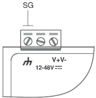
SG: The Shielded Ground (sometimes called Protected Ground) contact is the left most contact of the 3-pin power terminal block connector when viewed from the angle shown in the figure at the left. Connect the SG wire to an appropriate grounded metal surface.
Connecting Data Transmission Cables
This section describes how to connect the UC-71xx to the network, to serial devices, and to a serial COM terminal.
Connecting to the Network
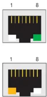
Connect one end of the Ethernet cable to the UC-71xx's 10/100M Ethernet port, and the other end of the cable to the Ethernet network. If the cable is properly connected, the UC-71xx will indicate a valid connection to the Ethernet in the following ways:
- The top-right LED on the connector glows a solid green when connected to a 100 Mbps Ethernet network.
- The top-left LED on the connector glows a solid orange when connected to a 10 Mbps Ethernet network.
- The LEDs will flash when Ethernet packets are being transmitted or received.
The 10/100 Mbps Ethernet LAN 1 and LAN 2 ports use 8-pin RJ45 connectors. Pinouts for these ports are given in the following diagram.
8-pin RJ45
| Pin Signal | |
| 1 | ETx+ |
| 2 | ETx- |
| 3 | ERx+ |
| 4 | --- |
| 5 | --- |
| 6 | ERx- |
| 7 | --- |
| 8 | --- |
Connecting to a Serial Device
Connect the serial cable between the UC-71xx and the serial device(s).
The two serial ports (P1 and P2) use male DB9 connectors, and can be configured for RS-232/422/485 by software. The pin assignments are shown in the following table:
Male DB9 Port
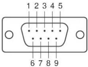
RS-232/422/485 Pinouts
| Pin RS-232 RS-422 | RS-485(4-wire) | RS-485(2-wire) | ||
| 1 | DCD | TxDA(-) | TxDA(-) | --- |
| 2 | RxD | TxDB(+) | TxDB(+) | --- |
| 3 | TxD | RxDB(+) | RxDB(+) | DataB(+) |
| 4 | DTR | RxDA(-) | RxDA(-) | DataA(-) |
| 5 | GND | GND | GND | GND |
| 6 | DSR | --- | --- | --- |
| 7 | RTS | --- | --- | --- |
| 8 | CTS | --- | --- | --- |
Serial Console Port
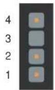
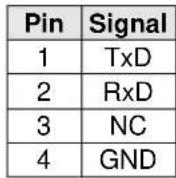
The serial console port is a 4-pin pin-header RS-232 port. It is designed for serial console terminals, which are useful for identifying the UC-71xx's boot up message.
Serial Console Port & Pinouts
Serial Console Cable
natural_image
Black cable with a U8 port connector and terminal connector (no text or symbols visible)- Hardware User's Manual
- UC-7112 LX Plus, UC-7112, UC-7110 Hardware User's Manual
- Copyright Notice
- Trademarks
- Disclaimer
- Technical Support Contact Information www.moxa.com/support
- Chapter 1 Introduction....1-1
- Chapter 2 Hardware Introduction....2-1
- Chapter 3 Hardware Connection Description ....3-1
- Overview
- Package Checklist
- Standard Operating Temperature Models (-10 to 60°C)
- UC-7110-LX
- UC-7112-LX
- UC-7112-LX Plus
- Wide Operating Temperature Model (-40 to 75°C)
- UC-7110-T-LX
- Product Features
- Product Specifications
- Hardware Specifications
- System
- Network Communication
- Serial Communication
- LEDs
- Power Requirements
- Mechanical
- Environment
- Regulatory Approvals
- Software Specifications—μClinux (UC-7110 and UC-7112)
- Supported Services and Daemons:
- Application Development Environment:
- Software Specifications—Linux (UC-7112 Plus)
- Hardware Block Diagram
- Appearance
- Dimensions
- Panel Views
- LED Indicators
- Internal SD Socket
- Additional Functions
- Reset Button
- ATTENTION
- Real Time Clock
- □ Wiring Requirements
- □ Connecting Data Transmission Cables
- Wiring Requirements
- Safety First!
- Wiring Caution!
- Temperature Caution!
- Connecting the Power
- Grounding the UC-71xx Embedded Computer
- Connecting Data Transmission Cables
- Connecting to the Network
- Connecting to a Serial Device
- Serial Console Port
Brand : Moxa
Model : UC-7112
Category : Thin client