
SND-3080F - Security Camera SAMSUNG - Free user manual and instructions
Find the device manual for free SND-3080F SAMSUNG in PDF.

| Product Type | Network Dome Camera |
| Dimensions | Ø150 x 120 mm |
| Weight | 1.2 kg |
| Power Supply | PoE (IEEE 802.3af) or 12V DC |
| Resolution | 2 Megapixels (1920x1080) |
| Lens | 3.6mm fixed lens |
| Night Vision | IR LEDs up to 20m |
| Video Compression | H.264, MJPEG |
| Network Interface | 10/100 Base-T Ethernet |
| Ingress Protection | IP66 |
| Operating Temperature | -10°C to 50°C |
| Main Functions | Motion detection, tampering alarm, day/night, wide dynamic range |
| Maintenance & Cleaning | Clean dome with soft dry cloth; avoid solvents |
| Safety | Use only supplied adapter; disconnect power before cleaning |
| Spare Parts & Repairability | Contact Samsung support; no user-serviceable parts |
| General Information | Compliant with NDAA; warranty 2 years |
Frequently Asked Questions - SND-3080F SAMSUNG
User questions about SND-3080F SAMSUNG
0 question about this device. Answer the ones you know or ask your own.
Ask a new question about this device
Download the instructions for your Security Camera in PDF format for free! Find your manual SND-3080F - SAMSUNG and take your electronic device back in hand. On this page are published all the documents necessary for the use of your device. SND-3080F by SAMSUNG.
USER MANUAL SND-3080F SAMSUNG
©2010 Samsung Techwin Co., Ltd. All rights reserved.
Trademark

SAMSUNG TECHWIN is the registered logo of Samsung Techwin Co., Ltd.
The name of this product is the registered trademark of Samsung Techwin Co., Ltd.
Other trademarks mentioned in this manual are the registered trademark of their respective company.
Restriction
Samsung Techwin Co., Ltd shall reserve the copyright of this document. Under no circumstances, this document shall be reproduced, distributed or changed, partially or wholly, without formal authorization of Samsung Techwin.
Disclaimer
Samsung Techwin makes the best to verify the integrity and correctness of the contents in this document, but no formal guarantee shall be provided. Use of this document and the subsequent results shall be entirely on the user's own responsibility. Samsung Techwin reserves the right to change the contents of this document without prior notice.
Warranty
If the product does not operate properly in normal conditions, please let us know. Samsung Techwin will resolve the problem for free of charge. The warranty period is 3 years. However, the followings are excluded:
- If the system behaves abnormally because you run a program irrelevant to the system operation.
• Deteriorated performance or natural worn-out in process of time
CAUTION
RISK OF ELECTRIC SHOCK. DO NOT OPEN

CAUTION: TO REDUCE THE RISK OF ELECTRIC SHOCK, DO NOT REMOVE COVER (OR BACK) NO USER SERVICEABLE PARTS INSIDE. REFER SERVICING TO QUALIFIED SERVICE PERSONNEL.
This symbol indicates that dangerous voltage consisting a risk of electric shock is present within this unit.
This symbol indicates that there are important operating and maintenance instructions in the literature accompanying this unit.
WARNING
- To reduce the risk of fire or electric shock, do not expose this appliance to rain or moisture.
- To prevent injury, this apparatus must be securely attached to the floor/wall in accordance with the installation instructions.
- If this power supply is used at 24V ac, a suitable plug adapter should be used.
- The camera is to be only connected to PoE networks without routing to the outside plant.
WARNING
- Be sure to use only the standard adapter that is specified in the specification sheet. Using any other adapter could cause fire, electrical shock, or damage to the product.
- Incorrectly connecting the power supply or replacing battery may cause explosion, fire, electric shock, or damage to the product.
- Do not connect multiple cameras to a single adapter. Exceeding the capacity may cause abnormal heat generation or fire.
- Securely plug the power cord into the power receptacle. Insecure connection may cause fi re.
- When installing the camera, fasten it securely and firmly. The fall of camera may cause personal injury.
-
Do not place conductive objects (e.g. screwdrivers, coins, metal parts, etc.) or containers filled with water on top of the camera. Doing so may cause personal injury due to fire, electric shock, or falling objects.
-
Do not install the unit in humid, dusty, or sooty locations. Doing so may cause fire or electric shock.
- If any unusual smells or smoke come from the unit, stop using the product. In such case, immediately disconnect the power source and contact the service center. Continued use in such a condition may cause fire or electric shock.
- If this product fails to operate normally, contact the nearest service center. Never disassemble or modify this product in any way. (SAMSUNG is not liable for problems caused by unauthorized modifications or attempted repair.)
- When cleaning, do not spray water directly onto parts of the product. Doing so may cause fire or electric shock
- Do not expose the product to the direct airflow from an air conditioner. Otherwise, it may cause moisture condensation inside the Clear Dome due to temperature difference between internal and external of the dome camera.
- If you install this product in a low-temp area such as inside a cold store, you must seal up the wiring pipe with silicon, so that the external air can not flow inside the housing. Otherwise, external high, humid air may flow inside the housing, pooling moisture or vapor inside the product due to a difference between internal and external temperature.
CAUTION
- Do not drop objects on the product or apply strong blows to it. Keep away from a location subject to excessive vibration or magnetic interference.
- Do not install in a location subject to high temperature (over 50^ C), low temperature (below -10^ C), or high humidity. Doing so may cause fire or electric shock.
- If you want to relocate the already installed product, be sure to turn off the power and then move or reinstall it.
- Remove the power plug from the outlet when there is a lighting storm. Neglecting to do so may cause fire or damage to the product.
- Keep out of direct sunlight and heat radiation sources. It may cause fire.
- Install it in a place with good ventilation.
- Avoid aiming the camera directly towards extremely bright objects such as sun, as this may damage the CCD image sensor.
- Apparatus shall not be exposed to dripping or splashing and no objects filled with liquids, such as vases, shall be placed on the apparatus.
- The Mains plug is used as a disconnect device and shall stay readily operable at any time.
- When using the camera outdoors, moisture may occur inside the camera due to temperature difference between indoors and outdoors. For this reason, it is recommended to install the camera indoors. For outdoor use, use the camera with built-in fan and heater.
FCC STATEMENT
This device complies with part 15 of the FCC Rules. Operation is subject to the following two conditions :
1) This device may not cause harmful interference, and
2) This device must accept any interference received including interference that may cause undesired operation.
CAUTION
This equipment has been tested and found to comply with the limits for a Class A digital device, pursuant to part 15 of FCC Rules. These limits are designed to provide reasonable protection against harmful interference when the equipment is operated in a commercial environment.
This equipment generates, uses, and can radiate radio frequency energy and, if not installed and used in accordance with the instruction manual, may cause harmful interference to radio communications. Operation of this equipment in a residential area is likely to cause harmful interference in which case the user will be required to correct the interference at his own expense.

IC Compliance Notice
This Class A digital apparatus meets all requirements of the Canadian Interference.-Causing Equipment Regulations of ICES-003.
CAUTION
Danger of explosion if battery is incorrectly replaced. Replace only with the same or equivalent type.
- Read these instructions.
- Keep these instructions.
- Heed all warnings.
-
Follow all instructions.
-
Do not use this apparatus near water.
-
Clean only with dry cloth.
-
Do not block any ventilation openings. Install in accordance with the manufacturer's instructions.
-
Do not install near any heat sources such as radiators, heat registers, or other apparatus (including amplifiers) that produce heat.
-
Do not defeat the safety purpose of the polarized or grounding-type plug. A polarized plug has two blades with one wider than the other. A grounding type plug has two blades and a third grounding prong. The wide blade or the third prong is provided for your safety. If the provided plug does not fit into your outlet, consult an electrician for replacement of the obsolete outlet.
-
Protect the power cord from being walked on or pinched particularly at plugs, convenience receptacles, and the point where they exit from the apparatus.
-
Only use attachments/accessories specified by the manufacturer.
-
Use only with the cart, stand, tripod, bracket, or table specified by the manufacturer, or sold with the apparatus. When a cart is used, use caution when moving the cart/apparatus combination to avoid injury from tip-over.
-
Unplug this apparatus during lightning storms or when unused for long periods of time.
-
Refer all servicing to qualified service personnel. Servicing is required when the apparatus has been damaged in any way, such as powersupply cord or plug is damaged, liquid has been spilled or objects have fallen into the apparatus, the apparatus has been exposed to rain or moisture, does not operate normally, or has been dropped.

natural_image
Symbolic icon of a person pushing a large object through a circular frame (no text or symbols)
Apparatus shall not be exposed to dripping or splashing and no objects filled with liquids, such as vases, shall be placed on the apparatus
CONTENTS
OVERVIEW
3
7 Important Safety Instructions
10 Product Features
10 Recommended PC Specifications
11 What's Included
12 At a Glance
INSTALLATION & CONNECTION
16
16 Removing the Covers
17 Inserting/Removing an SD Memory Card
18 Memory Card Information (Not Included)
19 Connecting with Other Device
21 Installation
CAMERA SETUP
24
24 How to Use the Keyboard Controller
25 Main Menu
25 Profi le
26 Camera Setup
31 Privacy Zone
32 Others
33 System Info
NETWORK CONNECTION AND SETUP
34
34 Connecting the Camera to an IP Router with the xDSL/Cable Modem
35 Connecting the Camera to an IP Router With Local Area Networking
36 Connecting the Camera Directly to a DHCP-Based xDSL/Cable Modem
37 Connecting the Camera Directly to Local Area Networking
38 Buttons Used in IP Installer
39 Static IP Setup
42 Dynamic IP Setup
43 Port Range Forward (Port Mapping) Setup
44 Connecting to the camera from a shared local PC
44 Connecting to the camera from a remote PC via the Internet
WEB VIEWER
45
45 Connecting to the Camera
46 Login
47 Installing Activex
48 Using the Live Screen
49 Backup
51 Using the SD Search Viewer Screen
SETUP SCREEN
52
52 Accessing the Setup Screen
53 Default Setup
58 System Setup
61 Overlay Setup
62 Event Setup
69 Network Setup
APPENDIX
70
70 Profi le
71 Terminology
72 Specifications
76 Frame Rate (NTSC)
82 Frame Rate (PAL)
88 Troubleshooting
90 GPL/LGPL Software License
PRODUCT FEATURES
• Support various communication protocols
Supports TCP/IP, UDP, RTP/RTSP, SMTP for email, and FTP protocols as well as various internet protocols such as ARP, HTTP, HTTPS and DHCP.
• Web Browser-based Monitoring
Using the Internet web browser to display the image in a local network environment.
• Automatic Local IP Setup
Even a network novice can install it with minimum operations.
- Alarm
If an alarm sensor is connected and it detects a motion, a message is sent to the registered address via FTP/email (SMTP) or stored in the SD memory card, or an alarm will signal to the alarm out terminal.
- Motion Detection
If the camera with a specified motion area detects a motion in that area, it will send a notification to a user FTP/email account (SMTP) or stored in the SD memory card, or send the corresponding signal to the Alarm Out terminal.
RECOMMENDED PC SPECIFICATIONS
• CPU : Pentium4 / 2.4GHz or higher
- Operating System : Windows XP(Service Pack2, Service Pack3) / Windows Vista / Windows 7
• Resolution : 1024X768 pixels or higher
• RAM : 512MB or higher
- Web Browser : Internet Explorer 6.0 or higher
• Video Card : Radeon, Nvidia
• Video Memory : 128MB
- DirectX 8.1 or higher
Compatible IP Routers
- Linksys
• D-Link - Netgear
Compatible PoE Switches
- Linksys SRW224G4P
• D-Link DES-1316 - SMC SMCPWR-INJ3
Please check if your camera and accessories are all included in the product package.
Camera
User Manual/
IP INSTALLER DVD
Quick Guide
Test Monitor Cable Screw Dust-proof Plate

The Test Monitor Cable is connected to a portable displayer and used for testing the camera. If you intend to use it for an actual monitoring camera, use the BNC cable instead.
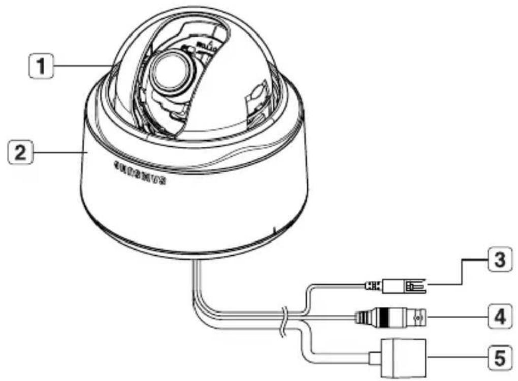
AT A GLANCE
Appearance
| Item Description | |
| 1 Dome Cover Case cover used to protect the lens and the main unit. | |
| 2 Main Unit | Consists of: lens, switch board, PCB and screws. |
| 3 Power Port | Used to plug in the power cable. |
| 4 Video Output Port | Used to connect the Video In connector of the monitor, from which the video signal of the camera outputs. |
| 5 Network Port Used to connect the PoE or LAN cable. | |

- Wipe out a dirty surface of the lens softly with a lens tissue or cloth to which you have applied ethanol.
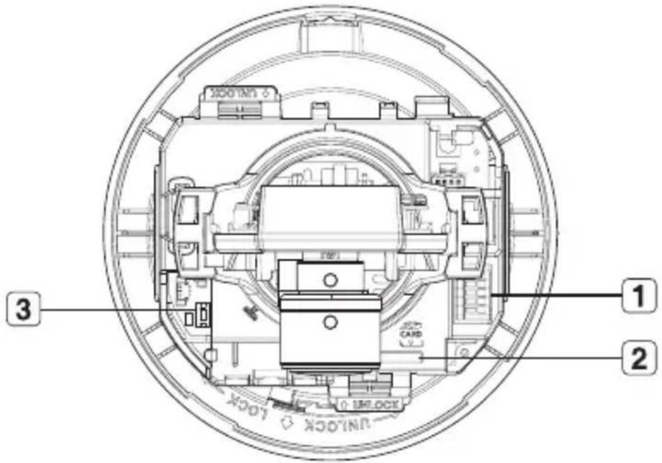
Inside
| Item Description | |
| 1 Alarm In / Out terminals | Alarm in/out terminals can be configured as follows:- ALARM IN : Terminal for Alarm Input.- ALARM OUT : Terminal for Alarm Output.- GND : Grounding terminal. |
| 2 SD Memory Card Compartment | Compartment for the SD memory card. |
| 3 Reset Button | Resets the camera settings.Press the button for about 3 seconds, and the system indicator turns off and will restart.! Resetting the camera r equires reconfiguration of network settings (IP address, subnet mask, gateway address etc.) using the IP Installer software application. |
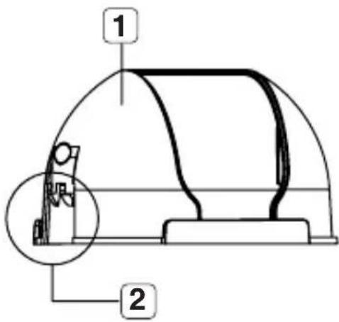
Components
| Item Description | ||
| 1 Inner Cover Cover used to protect the main unit. | ||
| 2 Wing-Side Hook Tap on either end to remove the inner cover. | ||
| 3 Monitor Out | The Test Monitor Cable is connected to a portable displayer and used for testing the camera. | |
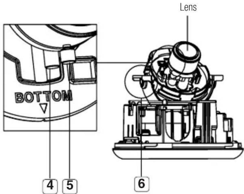
| 4 Zoom Lever Used to adjust or fix the zoom factor of the lens. | ||
| 5 Focus Lever | Turn it to the left or right to adjust the focus; turn it clockwise to fix the focus. | |
| 6 Tilt Screw Used to adjust or fix the tilt of the lens. | ||
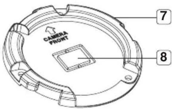
| 7 Bracket Used to install the camera on the wall or ceiling with the screws. | ||
| 8 Wiring Cover | If you drill a hole in the wiring cover for wiring, remove the cover and attach the provided dust-proof plate to it, and arrange the cables through the plate.The dust-proof plate is to prevent outside dust from inflow to the wiring compartment. | 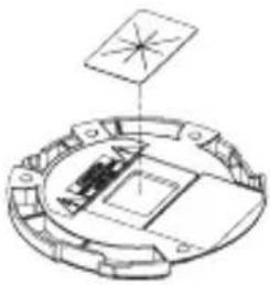 |
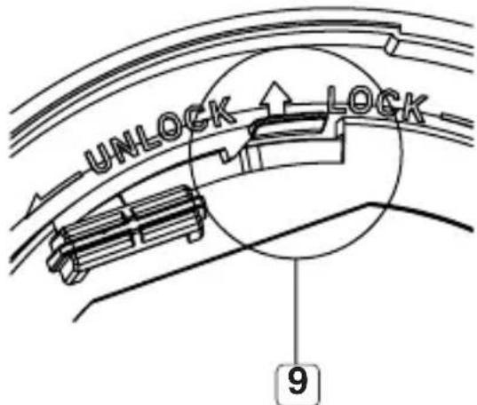
| 9 Release Lock | If you want to remove the bracket from the main unit or remove the camera from the bracket, push this out and turn the main unit in thedirection. | |
installation & connection
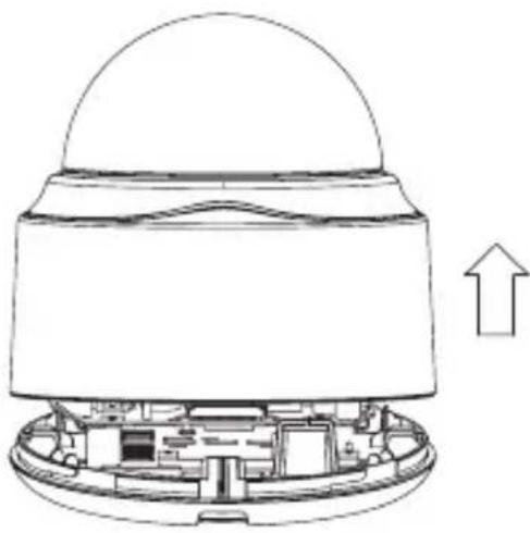
REMOVING THE COVERS
If you want to connect the Alarm I/O connectors, you must remove the dome cover and lens cover beforehand.
- Turn the dome cover counter-clockwise.
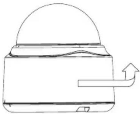
natural_image
Line drawing of a kettle with a dome-shaped lid and an arrow indicating fluid flow (no text or symbols)- Remove the dome cover by lifting it up.
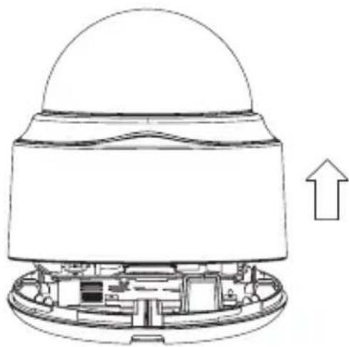
natural_image
Cross-sectional diagram of a device showing internal components and an upward arrow (no text or symbols)- Tap on either end of the lens cover to remove it.
natural_image
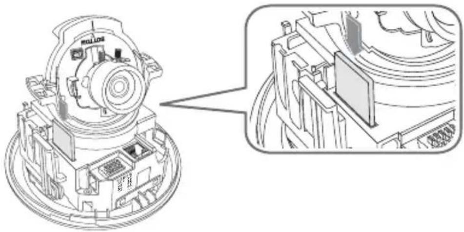
Technical line drawing of a mechanical assembly with a dome-shaped top component and internal components (no text or symbols)Inserting an SD Memory Card
Push the SD memory card in the direction of the arrow shown in the diagram.
natural_image
Technical line drawing of a mechanical assembly with exploded view (no text or symbols)Do not insert the SD memory card while it's upside down by force. Otherwise, it may damage the SD memory card.
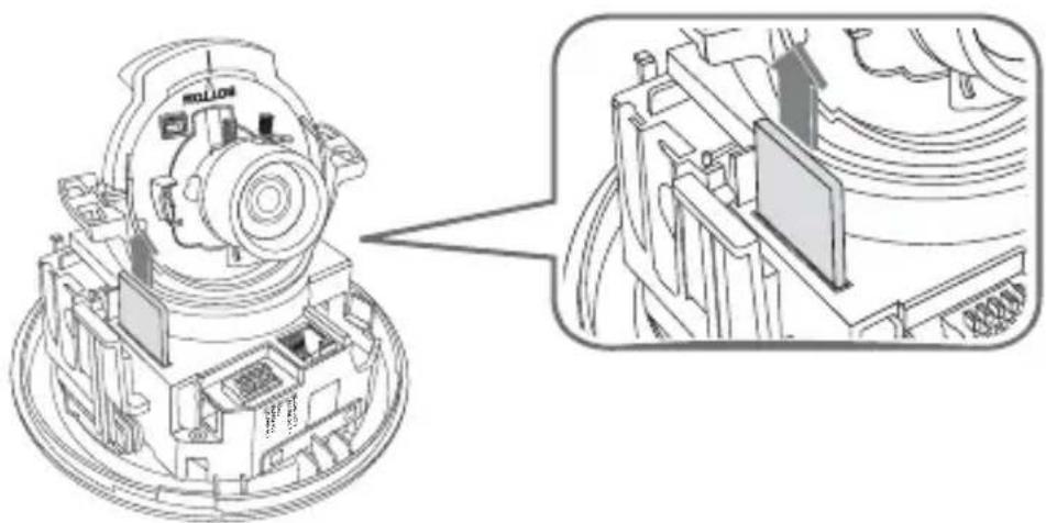
Removing an SD Memory Card
Gently press down on the exposed end of the memory card as shown in the diagram to eject the memory card from the slot.
natural_image
Technical line drawing of a mechanical assembly with exploded view (no text or symbols)- Pressing too hard on the SD memory card can cause the card to shoot out uncontrollably from the slot when released.
Before ejecting the SD memory card, release the checkboxin and press [Apply] button. (page 65)
MEMORY CARD INFORMATION (NOT INCLUDED)
What is a memory card?
The memory card is an external data storage device that has been developed to offer an entirely new way to record and share video, audio, and text data using digital devices.
Selecting a memory card that's suitable for you
Your camera supports SDHC memory cards.
You may, however, experience compatibility issues depending on the model and make of the memory card.
Your camera supports SD memory cards.
Note that supported memory card capacity is up to 2GB.
For your camera, we recommend you use a memory card from the following manufacturers: SDHC/SD Memory Card: Panasonic, Sandisk, Toshiba
Your camera supports 128MB to 16GB (SD Card : 2GB) of memory card capacity.
Playback performance can be affected depending on the speed of memory card, so use the high-speed memory card.
To ensure proper recording of video data, we recommend you use a memory card that supports at least read/write speed 10Mbps and Class 6.
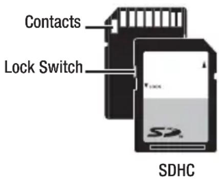
Memory Card Use
SD and SDHC memory cards feature a switch that disables writing data on to the media. Having this switch to the Lock position will prevent accidental deletion of data stored in the memory card but at the same time will also prevent you from writing data on to the media.
◆ Memory Card Components
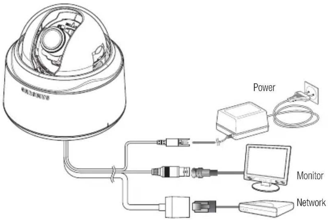
Power Supply
Connect the power adaptor to the power input port.
- Be careful not to reverse the polarity when you connect the power cable. You can also use a router featuring PoE (Power over Ethernet) to supply power to the camera.
Connecting to the monitor
Connect the [V_OUT] port of the camera to the video input port of the monitor.
Network Connection
Connect the Network cable to the local network or to the Internet.
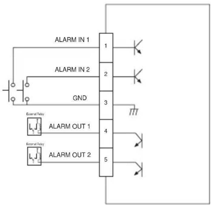
Connecting to the I/O port box
Connect the Alarm I/O cable to the corresponding port of the inner port box.
![ALARM IN [ 1 2 ] GND - 3 4 - ALARM OUT [ 5 ]](/content/2026/06/1146030/images/362f49688e557bd1987be5180269c00057dd0d681384c21ae3d2ef4dd7e9fa7f.jpg)
- ALARM IN 1, 2: Used to connect the alarm input signal.
• GND : Used for earth-grounding. - ALARM OUT 1, 2 : Used to connect the alarm output signal.
Alarm I/O Wiring Diagram
flowchart
graph TD
    A["ALARM IN 1"] --> B["1"]
    C["ALARM IN 2"] --> D["2"]
    E["GND"] --> F["3"]
    G["External Relay"] --> H["4"]
    I["External Relay"] --> J["5"]
    B --> K["Diode"]
    D --> L["Diode"]
    F --> M["Diode"]
    H --> N["Diode"]
    J --> O["Diode"]
Precautions before installation
Ensure you read the following instructions before installing the camera:
- Select an installation site (ceiling or wall) that can endure at least 5 times of the camera weight.
- Stuck-in or peeled-off cables can cause damage to the product or a fire.
- For safety purposes, keep anyone else away from the installation site. And put aside personal belongings from the site, just in case.
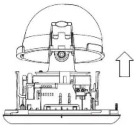
Installing the camera
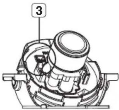
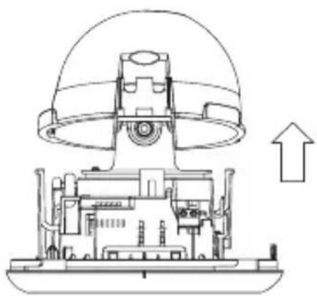
- Hold down the bottom lock lever while removing the cover with the other hand. Removing the cover reveals the main unit and inner cover.
natural_image
Cross-sectional diagram of a device showing internal components and an upward arrow (no text or symbols)- To fix the camera position, hold down either hook of the inner cover and lift it up.
natural_image
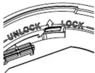
Technical line drawing of a mechanical assembly with a dome-shaped component and internal components (no text or symbols)- Push the release lock out while turning the main unit in the
direction to remove the bracket. If this doesn't work, use the hole on the bottom of the bracket to turn the bracket in the direction.
installation & connection
- Use the provided screws (x3) to fix the bracket to a desired position (ceiling or wall).
- Ensure that the
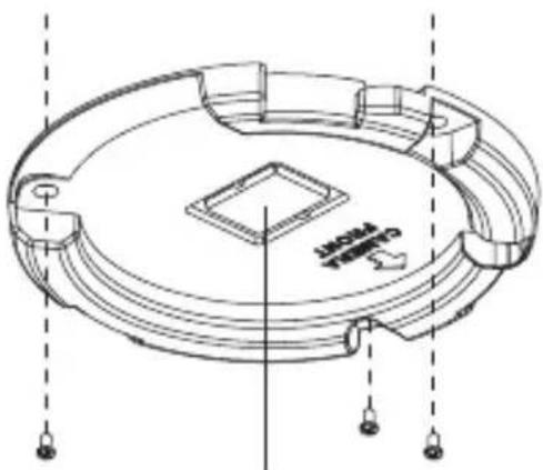
natural_image
Technical line drawing of a circular mechanical component with mounting holes and internal features (no text or symbols)Wiring Cover
- Arrange the cables through the bracket to the ceiling or wall.
If you drill a hole in the ceiling cover for wiring, press hard to remove the cover and attach the dust-proof plate to it, and arrange the cables through the plate. If you intend to arrange the cables without drilling a hole, use the empty area opposite to the
- Mount the main unit onto the bracket.
Align the marking hole of the main unit with the
- Adjust the lens in a desired direction.
For adjusting the lens direction, refer to "Adjusting the monitoring direction for the camera".
- Secure the inner cover to the main unit.
Fit the two holes of the wing-side locks on the inner cover into the corresponding hole of the main unit, and press it down until you hear a click.
- Fix the cover to the main unit.
Fit the protruding part inside the cover into the corresponding hole of the main unit, and turn the cover to fi x it.
Adjusting the monitoring direction for the camera
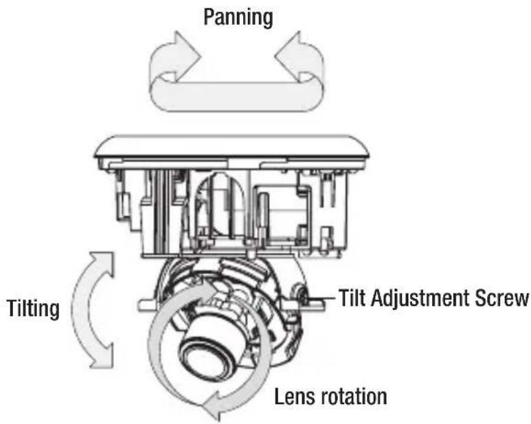
You can adjust the camera direction only when the camera is fixed on the ceiling.
Then, turning the camera to the left or right is referred to as "Panning", while tilting the angle is "Tilting". For panning, the panning limit is 220^ for the clockwise, and 120^ for the counterclockwise, a total of 340^ enabled; further rotation is stopped by the stopper.
Adjusting the zoom and focus
Watch the camera's real time video and rotate the "Zoom lever" to zoom in/out the subject as you want.
Rotate the "Focus lever" until the image looks clear.
For the position of the Zoom lever and Focus lever, refer to the "Components" (page 14).

It is recommended to install the camera 2.5M\~10M high above from the floor.
You can configure the camera settings using the Web Viewer.

For accessing the Web Viewer, refer to "Network Connection and Setup". (page 34)
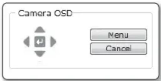
HOW TO USE THE KEYBOARD CONTROLLER
Follow the steps below if you run the Web Viewer for setting the menus.
- Launch the Web Viewer.
- From the [Camera OSD] menu in the left pane, click [Menu].
Thescreen appears. - Click the Up/Down (▲▼) buttons to move to a desired item.
-
Click the four direction (▲▼◀▶) buttons to navigate through the menu items.
-
To change the value of a selected item, click the Left/Right (◀ ▶) buttons.
-
Click [←].
Your changes will be applied.
: Exits the menu setup screen.
Before exiting the setup screen, select [SAVE] to save your settings, or [QUIT] to cancel them.
: Saves your settings and returns to the previous screen.
☐: Use this icon if you want to save your settings after you specified the mask area and privacy area, etc.
Once you saved your settings, the changes remain intact even if you select [QUIT] on exit.
: Use this icon if you want to delete a mask, or privacy area, etc.
Once you deleted your settings, the deletions remain valid even if you select [QUIT] on exit.
: This arrow appears next to a menu that contains sub items.
For the items with the "*" mark on the right, You can get help from "Terminology". (page 71)
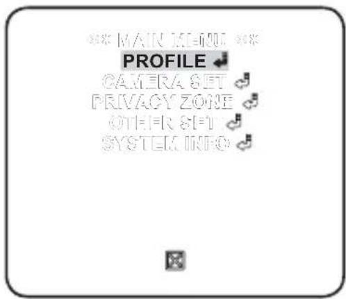
You can configure the camera settings to your preference.
- PROFILE
You can select a mode that is appropriate to the camera installation environment. - CAMERA SET
Conf i gure the camera functions and settings. - PRIVACY ZONE
You can configure the privacy settings. - OTHER SET
You can configure more settings including FACTORY DEFAULTS. - SYSTEM INFO
Shows the camera version and type.
PROFILE
You can select one from the pre-determined modes as appropriate to your specific camera installation environment.
Your selection on each item in PROFILE will affect all other settings of the camera. For the setting, refer to "PROFILE". (page 70)
For selecting and saving each menu item, refer to "How to use the keyboard controller". (page 24)
- STANDARD
Automatically optimizes the camera settings to the normal environment.
• ITS
This setting enables you to analyze the traffic situation and take the traffic information at a glance. - BACKLIGHT
This setting enables you to view a sharp background and object even in a severe backlight scene.
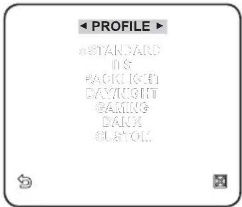
- DAY/NIGHT
Automatically optimizes the camera settings to the day and night scene.
• GAMING
This automatically configures the settings so that you can work in a stable illumination condition as indoors.
• BANK
Automatically optimizes the camera settings to the bank environment.
- CUSTOM
Your change to any of the PROFILE settings will switch the display to CUSTOM.
CAMERA SETUP
You can configure the general settings of the camera module. Use the four direction (▲▼◀▶) buttons to select a desired item.
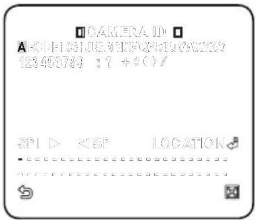
CAMERA ID
Provide the ID and position for a camera that displays on the screen.
For selecting and saving each menu item, refer to "How to use the keyboard controller". (page 24)
- Select
- . - Use the four direction (▲▼◀▶) buttons to select a desired character. In the lower input box of the screen, the selected character will be entered.
- You can enter up to 54 characters including alphabets, numbers and special characters.
- When done, continue to select
to specify the display position of the camera ID.
MOTION
You can specify a level of AGC for controlling the camera motion. Select F.FAST if you want to monitor a very fast moving object in a low contrast scene, and S.SLOW if monitoring a very slow moving, inanimate object in the same condition. As long as DAY/NIGHT is set to AUTO, theDNR
Reduces the noise on the screen. This is useful, especially for a noisy screen. Set it toSHUTTER
The SHUTTER menu is used to set the fixed fast electronic shutter or auto fast electronic shutter.SENS-UP
If the brightness of the video signal is too low, the Slow Shutter function will be activated. Slow Shutter can collect the individual max frame rate to adjust the setting.  FLICKERLESS
If set toXDR
This will correct a brightness difference between different scenes for the optimal visibility. The higher the value is, the higher the correction level is.DIS
Automatically compensates for the flicker on the screen. If set toDAY/NIGHT
You can specify a recording mode according to the scene. For selecting and saving each menu item, refer to "How to use the keyboard controller". (page 24) 1. SelectWHITE BAL
If you need to adjust the screen brightness, use the WHITE BALANCE function. For selecting and saving each menu item, refer to "How to use the keyboard controller". (page 24) 1. SelectDIGITAL ZOOM
You can set the digital zoom factor and position. When the zoom factor and position are defined, the digital zoom function will operate. If you set the digital zoom to a larger factor than the actual enlargement for compensation, the DIS function will be disabled.DETAIL
You can adjust the vertical and horizontal sharpness, respectively.AGC COLOR SUP
This will adjust the color scheme according to the AGC value.REVERSE
This will reverse the signal left to right, top to bottom, or a combination of the preceding.POSI/NEGA
This will display the video brightness signal either normally or reversely.PIP
You can view a main image with a sub image on the same screen. If more than one privacy zone is set and the PRIVACY SET is set to ON, the PIP function will be deactivated. You can set up to 12 privacy zones that will be hided for privacy of the subject when recording. For selecting and saving each menu item, refer to "How to use the keyboard controller". (page 24)ZONE SETUP
1. Select- Trademark
- Restriction
- Disclaimer
- Warranty
- CAUTION
- WARNING
- FCC STATEMENT
- IC Compliance Notice
- CONTENTS
- OVERVIEW
- INSTALLATION & CONNECTION
- CAMERA SETUP
- NETWORK CONNECTION AND SETUP
- WEB VIEWER
- SETUP SCREEN
- APPENDIX
- PRODUCT FEATURES
- • Support various communication protocols
- • Web Browser-based Monitoring
- • Automatic Local IP Setup
- - Alarm
- - Motion Detection
- RECOMMENDED PC SPECIFICATIONS
- Compatible IP Routers
- Compatible PoE Switches
- AT A GLANCE
- Inside
- REMOVING THE COVERS
- Inserting an SD Memory Card
- Removing an SD Memory Card
- MEMORY CARD INFORMATION (NOT INCLUDED)
- What is a memory card?
- Selecting a memory card that's suitable for you
- Memory Card Use
- ◆ Memory Card Components
- Power Supply
- Connecting to the monitor
- Network Connection
- Connecting to the I/O port box
- Alarm I/O Wiring Diagram
- Precautions before installation
- Installing the camera
- Adjusting the monitoring direction for the camera
- Adjusting the zoom and focus
- HOW TO USE THE KEYBOARD CONTROLLER
- PROFILE
- CAMERA ID
- IRIS
- MOTION
- DNR
- SHUTTER
- SENS-UP
- FLICKERLESS
- XDR
- DIS
- DAY/NIGHT
- WHITE BAL
- DIGITAL ZOOM
- DETAIL
- AGC COLOR SUP
- REVERSE
- POSI/NEGA
- PIP
- ZONE SETUP
- OTHERS
- LANGUAGE
- FACTORY DEFAULT
- OSD COLOR
- CONNECTING THE CAMERA TO AN IP ROUTER WITH THE XDSL/CABLE MODEM
- Configuring the network settings of the local PC connected to an IP router
- Checking if the IP router is connected to the xDSL/Cable modem properly
- Select from the Settings menu of the IP Router
- CONNECTING THE CAMERA TO AN IP ROUTER WITH LOCAL AREA NETWORKING
- CONNECTING THE CAMERA DIRECTLY TO A DHCP-BASED XDSL/CABLE MODEM
- Setting the IP Router
- CONNECTING THE CAMERA DIRECTLY TO LOCAL AREA NETWORKING
- Connecting to the camera from a local PC in the LAN
- STATIC IP SETUP
- Manual Network Setup
- If using an IP router :
- If not using an IP router :
- If the IP router has more than one camera connected
- Auto Network Setup
- DYNAMIC IP SETUP
- Dynamic IP Environment Setup
- Checking the dynamic IP
- PORT RANGE FORWARD (PORT MAPPING) SETUP
- Manual Port Range Forwarding
- CONNECTING TO THE CAMERA FROM A SHARED LOCAL PC
- CONNECTING TO THE CAMERA FROM A REMOTE PC VIA THE INTERNET
- CONNECTING TO THE CAMERA
- Normally, you would
- If the HTTP port is other than 80
- Using URL
- Connecting via URL (If the HTTP port is other than 80)
- To check the DDNS address
- LOGIN
- For Windows XP Service Pack 2 users
- BACKUP
- To capture the snapshot
- To print out the screenshot
- To record a video
- ACCESSING THE SETUP SCREEN
- To configure the video settings
- Select - .
- To configure the IP settings
- When done, click [Apply].
- To set the user account
- Click - .
- User Registration
- Click [Apply].
- To edit a registered user account
- To delete a user ID
- ■ About the user permission
- To set the display language
- SYSTEM SETUP
- To set the date/time
- To set the system time
- To check the log information
- To update the software
- How to update the software
- To reset the system
- To set the HTTPS
- OVERLAY SETUP
- To set the text
- EVENT SETUP
- To set the event transfer function
- To test the FTP transfer
- To test the email transfer
- Click [Test].
- To setup the record
- To set an alarm image
- To set the alarm input
- To set the motion detection function
- To set a motion area
- To set the scheduled transfer
- To set the video transfer mode
- To set the DDNS
- FRAME RATE (NTSC)
- FRAME RATE (PAL)
- GNU GENERAL PUBLIC LICENSE
- Preamble
- TERMS AND CONDITIONS FOR COPYING, DISTRIBUTION AND MODIFICATION
- NO WARRANTY
- END OF TERMS AND CONDITIONS
- How to Apply These Terms to Your New Programs
- TERMS AND CONDITIONS
- Definitions.
- Source Code.
- Basic Permissions.
- Protecting Users' Legal Rights From Anti-Circumvention Law.
- Conveying Verbatim Copies.
- Conveying Modifi ed Source Versions.
- Conveying Non-Source Forms.
- Additional Terms.
- Termination.
- Acceptance Not Required for Having Copies.
- Automatic Licensing of Downstream Recipients.
- Patents.
- No Surrender of Others' Freedom.
- Use with the GNU Affero General Public License.
- Revised Versions of this License.
- Disclaimer of Warranty.
- Limitation of Liability.
- Interpretation of Sections 15 and 16.
- GNU LESSER GENERAL PUBLIC LICENSE
- How to Apply These Terms to Your New Libraries
- OpenSSL LICENSE
- Original SSLeay License
- Correct Disposal of This Product (Waste Electrical & Electronic Equipment)
- SALES NETWORK
Brand : SAMSUNG
Model : SND-3080F
Category : Security Camera