
FOX II AEX 108 MM - Audio/Video Equipment Extron - Free user manual and instructions
Find the device manual for free FOX II AEX 108 MM Extron in PDF.

| Product Type | Eight Input Fiber Optic Audio Extractor |
| Model | FOX II AEX 108 MM |
| Brand | Extron |
| Category | Audio/Video Equipment |
| Transmission Type | Multimode (850 nm) |
| Input Connectors | Eight fiber optic LC connectors with buffered loop-throughs |
| Output Connectors | Eight 5-pole captive screw connectors for balanced or unbalanced analog stereo audio |
| Audio Extraction | Simultaneous extraction for up to eight FOX Series or FOX II Series fiber optic signals |
| Output Reclocking | Reshapes and restores timing of the digital signal |
| Data Rate Selection | Selectable 2G or 4G input data rates via recessed toggle switch |
| LED Indicators | Power, audio signal presence, and fiber link status (Tx/Rx) LEDs |
| Compatibility | All FOX Series and FOX II Series products except FOX 3G HD-SDI and FOX 3G DVC models |
| Enclosure | 1U high, half-rack width metal enclosure |
| Mounting | Rack-mountable or tabletop with rubber feet |
| Power Supply | Internal universal power supply, 100-240 VAC, 50/60 Hz |
| Laser Safety | Class 1 Laser Product; complies with FDA and IEC 60825-1 |
| Operating Temperature | Not specified; install in environment compatible with max ambient temperature per Extron specifications |
| Maintenance | No user-serviceable parts; service only by Extron qualified personnel |
| Repair | Contact Extron for authorized repair; return unit with RA number |
| Warranty | Three years from date of purchase against defects in materials and workmanship |
| Dimensions (Approximate) | 1.75" H x 8.5" W x 6.0" D (4.4 cm x 21.6 cm x 15.2 cm) typical half-rack |
| Weight (Approximate) | 2.5 lbs (1.1 kg) typical |
Frequently Asked Questions - FOX II AEX 108 MM Extron
User questions about FOX II AEX 108 MM Extron
0 question about this device. Answer the ones you know or ask your own.
Ask a new question about this device
Download the instructions for your Audio/Video Equipment in PDF format for free! Find your manual FOX II AEX 108 MM - Extron and take your electronic device back in hand. On this page are published all the documents necessary for the use of your device. FOX II AEX 108 MM by Extron.
USER MANUAL FOX II AEX 108 MM Extron
Eight Input Fiber Optic Audio Extractors

Safety Instructions
Safety Instructions • English
WARNING: This symbol, , when used on the product, is intended to alert the user of the presence of uninsulated dangerous voltage within the product's enclosure that may present a risk of electric shock.
ATTENTION: This symbol, △when used on the product, is intended to alert the user of important operating and maintenance (servicing) instructions in the literature provided with the equipment.
For information on safety guidelines, regulatory compliances, EMI/EMF compatibility, accessibility, and related topics, see the Extron Safety and Regulatory Compliance Guide, part number 68-290-01, on the Extron website, www.extron.com.
Chinese Traditional (繁體中文)
CLASS 1 LASER PRODUCT
Complies with FDA performance standards for laser products except for deviations pursuant to Laser Notice No. 5, dated June 24, 2007.
The product is intended to be used with the fiber optic cables fully installed.
This product meets the applicable requirements of IEC 60825-1, Edition 1 (2007).
Any service to this product must be carried out by Extron Electronics and its qualified service personnel.
NOTE: For more information on safety guidelines, regulatory compliances, EMI/EMF compatibility, accessibility, and related topics, see the “Extron Safety and Regulatory Compliance Guide” on the Extron website.
FDA/IEC 60825-1 Prérequis
© 2014 Extron Electronics. All rights reserved.
Trademarks
All trademarks mentioned in this guide are the properties of their respective owners.
The following registered trademarks®, registered service marks ^(SM) , and trademarks ^(TM) are the property of RGB Systems, Inc. or Extron Electronics:
| Registered Trademarks ^(®) |
| AVTrac, Cable Cubby, CrossPoint, eBUS, EDID Manager, EDID Minder, Extron, Flat Field, GlobalViewer, Hideaway, Inline, IP Intercom, IP Link, KeyMinder, LockIt, MediaLink, PlenumVault, PoleVault, PowerCage, Pure3, Quantum, SoundField, SpeedMount, SpeedSwitch, System INTEGRATOR, TeamWork, TouchLink, V-Lock, VersaTools, VN-Matrix, VoiceLift, WallVault, WindoWall, XTP, and XTP Systems |
| Registered Service Mark ^(SM) : S3 Service Support Solutions |
| Trademarks ^(TM) |
| AAP, AFL (Accu-Rate Frame Lock), ADSP (Advanced Digital Sync Processing), Auto-Image, CableCover, CDRS (Class D Ripple Suppression), DDSP (Digital Display Sync Processing), DMI (Dynamic Motion Interpolation), Driver Configurator, DSP Configurator, DSVP (Digital Sync Validation Processing), DTP, eLink, EQIP, FastBite, FlexOS, FOXBOX, GlobalConfigurator, IP Intercom HelpDesk, LinkLicense, MAAP, MicroDigital, ProDSP, QS-FPC (QuickSwitch Front Panel Controller), Scope-Trigger, SIS (Simple Instruction Set), Skew-Free, SpeedNav, Triple-Action Switching, WebShare, XTRA, ZipCaddy, ZipClip |
Conventions Used in this Guide
Notifications
The following notifications are used in this guide:
WARNING: Potential risk of severe injury or death.
NOTE: A note draws attention to important information.
TIP: A tip provides a suggestion to make working with the application easier.
Specifications Availability
Product specifications are available on the Extron website, www.extron.com.
Contents
Introduction.... 1
About this Guide....1
About the FOX AEX 108 and FOX II AEX 108
Fiber Optic Audio Extractors....1
Features 2
Application Diagrams....3
Point-to-point Application 3
Input Side of a Fiber Matrix Application 4
Output Side of a Fiber Matrix Application......5
Installation and Operation....6
Rear Panel Features 6
Front Panel Features....7
System Operation....8
Wiring Configurations 8
Changing the Input Data Rate......8
Reference Information 9
Mounting....9
Tabletop Use 9
UL Guidelines for Rack-Mounting 9
Introduction
This section contains basic information about this guide and the Extron FOX AEX 108 and FOX II AEX 108 Fiber Optic Audio Extractors. Topics in this section include:
- About this Guide
- About the FOX AEX 108 and FOX II AEX 108 Fiber Optic Audio Extractors
- Features
• Application Diagrams
About this Guide
This guide contains installation and operation information about the FOX AEX 108 and FOX II AEX 108 Fiber Optic Audio Extractors. Each device is available in two transmission modes:
- Singlemode — Includes a 1310 nm SFP module. The FOX AEX 108 SM and the FOX II AEX 108 SM are singlemode models.
- Multimode — Includes a 850 nm SFP module. The FOX AEX 108 MM and the FOX II AEX 108 MM are multimode models.
In this guide, the term “FOX AEX 108” refers to the FOX Series audio extractors which includes the FOX AEX 108 SM and FOX AEX 108 MM. The term “FOX II AEX 108” refers to the FOX II Series audio extractors which includes the FOX II AEX 108 SM and FOX II AEX 108 MM. The terms “extractors” and “audio extractors” refer to all FOX AEX 108 and FOX II AEX 108 Fiber Optic Audio Extractor models.
NOTE: A color-coded sticker on the rear panel identifies the type of SFP module: orange for multimode and yellow for singlemode.
About the FOX AEX 108 and FOX II AEX 108 Fiber Optic Audio Extractors
The extractors are eight input fiber audio extraction products that extract local audio in a fiber matrix or point-to-point applications. It can be installed on the output side of the fiber matrix.
NOTES:
- The multimode and singlemode extractors are physically and functionally identical with the exception of the effective range of transmission.
- The FOX AEX 108 extractors are compatible with all FOX series products except for FOX 3G HD-SDI, PowerCage FOX 3G HD-SDI and FOX 3G DVC models.
- The FOX II AEX 108 extractors are compatible with all FOX Series and FOX II Series products except for FOX 3G HD-SDI, PowerCage FOX 3G HD-SDI and FOX 3G DVC models.
- Different modes are not compatible with each other.
Features
Local audio outputs — Local audio outputs for up to eight FOX Series or FOX II Series fiber optic signals, extracting analog stereo audio for independent processing and routing
Inputs — Eight fiber optic LC connectors with buffered Loop-throughs
Outputs — Eight 5-pole captive screw connectors for balanced or unbalanced analog stereo audio
Simultaneous audio extraction ports — Depending on the model, each port accepts signals from either FOX Series or FOX II Series fiber optic products to provide local analog stereo audio output, and retransmits the fiber optic signal at the original power level.
Buffered input loop-throughs — Full transmitter power on each output maximizes distance capabilities by ensuring full availability of optical loss budget.
Balanced or unbalanced analog audio outputs — Provide balanced or unbalanced stereo audio on captive screw output connectors for integration with audio processing and distribution equipment.
Output reclocking — Reshapes and restores timing of the digital signal.
Multimode and singlemode availability — Available as an 850 nm multimode model for moderate-range transmissions and a 1310 nm singlemode model for extreme distances up to 30 km (18.75 miles). The extractor, connected between a FOX Series or FOX II Series transmitter and receiver, effectively doubles the overall transmission distance capability. For singlemode applications, signals can be sent up to 60 km (37.5 miles) from a transmitter to a receiver via the extractor.
Reliable physical connectivity — Industry standard LC connectors provide reliable physical connectivity and precise fiber core alignment.
Real-time status LED indicators — Front and rear panel LEDs verify signal presence, link status, and power for troubleshooting and monitoring.
Compatibility with the following Extron FOX Series or FOX II Series:
- Matrix switchers — Provides a convenient location for audio extraction in a matrix switching environment for signal distribution systems up to 1000x1000 and larger. Each port includes an input with a loop-through, enabling in-line installation without using valuable dedicated switching resources or a matrix switcher slot.
- Distribution amplifiers — Supports virtually any fiber optic switching and distribution environment for maximum design flexibility.
- HDMI, DisplayPort, DVI Plus, DVI, VGA, VGA/YUV, and AV transmitters and receivers — Provides audio extraction for a wide variety of sources and displays.
NOTES:
- The FOX AEX 108 extractors are compatible with all FOX Series products except for the FOX 3G HD-SDI extender or FOX 3G DVC signal converter.
- The FOX II AEX 108 extractors are compatible with all FOX Series and FOX II Series products except for the FOX 3G HD-SDI extender or the FOX 3G DVC signal converter.
• Transmission of HDMI and DisplayPort video and HDCP content requires two fibers.
Rack-mountable — Compact 1U half-rack width metal enclosure enables up to 16 extraction ports in a 1U rack space.
Internal universal power supply — The 100-240 VAC, 50 or 60 Hz, international power supply provides worldwide power compatibility.
Input Data Rate Selection — A recessed toggle switch on the front panel allows for selectable input data rates. The extractors can be set to 2G or 4G rates. These selectable rates apply to all inputs; they are not for individual inputs.
Application Diagrams
The extractors can be used anywhere local audio-only outputs are required. This may include the input or output side of a fiber optic matrix application or between a fiber optic transmitter and receiver. Integrating the extractor on the input side of a FOX matrix switcher allows for independent processing of source audio signals by a DSP processor. Integrating the extractor on the output side of a FOX matrix switcher routes the audio to amplifiers or a DSP processor. The extractors include eight extraction points for eight inputs. Each audio extraction point works independently.
NOTES:
- The extraction points in all three applications work independently.
- Transmission of HDMI or DisplayPort video with HDCP content requires a return fiber optic cable from the receiving device to the transmitting device.
The following applications are examples of typical integrations of the extractors in fiber optic systems.
Point-to-point Application
In systems without a fiber matrix switcher, the extractors can be incorporated between the fiber transmitter and the fiber receiver.

flowchart
graph TD
    A["Laptop"] --> B["Extron FOX II T DP\nFiber Optic Transmitter"]
    B --> C["Extron FOX II AEX 108\nFOX Series Audio Extractor"]
    C --> D["Extron SI 28\nSurface-mount Speakers"]
    D --> E["Extron FOX II R DP\nFiber Optic Receiver"]
    E --> F["Display"]
    C --> G["Extron XPA 1002\nPower Amplifier"]
    G --> H["Yellow arrow indicates connection path"]
Figure 1. Typical Integration of an Extractor in a Point-to-point Application
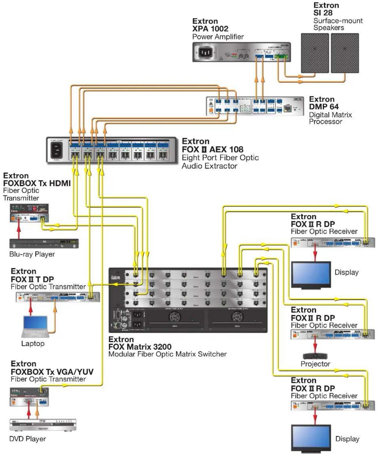
Input Side of a Fiber Matrix Application
An extractor can be placed on the input side of a fiber matrix switcher for independent processing of source audio signals by a DSP processor.
flowchart
graph TD
    A["Extron XPA 1002 Power Amplifier"] --> B["Extron SI 28 Surface-mount Speakers"]
    B --> C["Extron DMP 64 Digital Matrix Processor"]
    C --> D["Extron FOX II AEX 108 Eight Port Fiber Optic Audio Extractor"]
    D --> E["Extron FOX BOX Tx HDMI Fiber Optic Transmitter"]
    E --> F["Blu-ray Player"]
    F --> G["Laptop"]
    G --> H["Extron FOX II T DP Fiber Optic Transmitter"]
    H --> I["Extron FOX BOX Tx VGA/YUV Fiber Optic Transmitter"]
    I --> J["DVD Player"]
    D --> K["Extron FOX Matrix 3200 Modular Fiber Optic Matrix Switcher"]
    K --> L["Extron FOX II R DP Fiber Optic Receiver"]
    L --> M["Display"]
    K --> N["Extron FOX II R DP Fiber Optic Receiver"]
    N --> O["Projector"]
    K --> P["Extron FOX II R DP Fiber Optic Receiver"]
    P --> Q["Display"]
Figure 2. Typical Integration of an Extractor on the Input Side of a Fiber Matrix Application
Output Side of a Fiber Matrix Application
An extractor can also be placed on the output side of a FOX matrix switcher for routing to audio amplifiers or a DSP processor.

flowchart
graph TD
    A["Extron FOX II AEX 108<br>Eight Port Fiber Optic Audio Extractor"] --> B["Extron FOX BOX Tx HDMI<br>Fiber Optic Transmitter"]
    A --> C["Extron FOX II T DP<br>Fiber Optic Transmitter"]
    A --> D["Extron FOX BOX Tx VGA/YUV<br>Fiber Optic Transmitter"]
    A --> E["Extron FOX Matrix 3200<br>Modular Fiber Optic Matrix Switcher"]
    F["Extron XPA 1002<br>Power Amplifier"] --> G["Extron SI 28<br>Surface-mount Speakers"]
    G --> H["Extron DMP 64<br>Digital Matrix Processor"]
    I["Blu-ray Player"] --> J["Extron FOX BOX Tx HDMI<br>Fiber Optic Transmitter"]
    K["Laptop"] --> L["Extron FOX II T DP<br>Fiber Optic Transmitter"]
    M["DVD Player"] --> N["Extron FOX BOX Tx HDMI<br>Fiber Optic Transmitter"]
    O["Extron FOX II R DP<br>Fiber Optic Receiver"] --> P["Display"]
    Q["Extron FOX II R DP<br>Fiber Optic Receiver"] --> R["Projector"]
    S["Extron FOX II R DP<br>Fiber Optic Receiver"] --> T["Display"]
Figure 3. Typical Integration of an Extractor on the Output Side of a Fiber Matrix Application
FOX AEX 108 and FOX II AEX 108 Fiber Optic Audio Extractors • Introduction 5
Installation and Operation
This section provides cabling and operating information for the extractors. Topics in this section include:
- Rear Panel Features
- Front Panel Features
• System Operation
Rear Panel Features
The extractors include eight extraction points for audio extraction. Each extraction point includes a fiber optic connector (with a transmitter and receiver port) and an audio output connector.
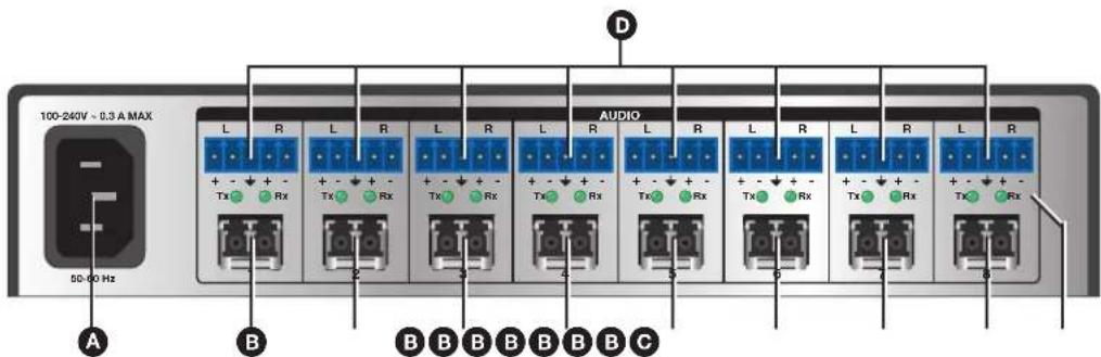
Figure 4. Rear Panel Connectors (FOX II AEX 108 Shown)
AC power connector — Plug a standard IEC power cord into the connector to connect the extractor to a 120 V or 240 VAC, 50 or 60 Hz power source.
B Fiber optic connectors — One dual port LC SFP module for fiber Tx or Rx transmission with two LEDs for fiber link status.
WARNING: These units output continuous invisible light; use with caution. Plug the attached dust caps into the optical transceivers when the fiber cable is unplugged.
NOTE: Ensure the proper fiber cable is used. Typically, singlemode fiber optic cables have a yellow jacket and multimode fiber optic cables have an orange or aqua jacket.
Tx connector — Connect a fiber optic cable to the Tx port of the extractor to an Rx port of a FOX receiver or FOX matrix switcher input.
Rx connector — Connect a fiber optic cable to the Rx port of the extractor to a Tx port of a FOX transmitter or FOX matrix switcher output.
C Tx and Rx indicator LEDs — The optical Tx and Rx LED indicators light to indicate light presence.
D Audio connectors — Insert a 3.5 mm, 5-pole captive screw audio connector for each extraction point. This output is unamplified line level audio. Wire the connector as shown in figure 5.
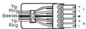
Balanced Audio Output
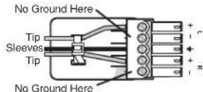
Unbalanced Audio Output
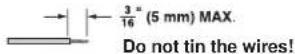
Figure 5. Captive Screw Connector Wiring for Audio Signals
Front Panel Features

Figure 6. Front Panel Features
A Power LED indicator — Lights when power is applied.
Audio Signal LED indicators — Each indicator lights when an audio signal above -35 dBV is detected on the associated fiber input. The LED lights immediately when the signal goes above that threshold, but turns off after the audio signal level remains below the threshold for 10 seconds.
C Recessed toggle switch — A recessed toggle switch that selects the input reclocking to maintain signal integrity on all inputs. Selects between 2G and 4G input data rates.
NOTE: The default switch position is down (4G).
System Operation
Wiring Configurations
The extractors can be used anywhere local audio-only outputs are required (see
Application Diagrams on page 3 for potential applications). Each extraction point on the extractor works independently—the audio extracted from the extraction point is taken from the associated fiber connector.
Transmission of HDMI or DisplayPort video with HDCP content requires a return fiber optic cable between the endpoints. Otherwise, digital video output by the receiver will not be HDCP-compliant and RS-232 reports will not be available from the controlled device. For this bidirectional serial communication and HDCP-compliance along an extraction point on the extractor, connect a fiber optic cable between the Rx port on the transmitter and the Tx port on the receiver.
NOTES:
- Upon startup, all Audio Signal LEDs blink together to identify SFP module. The LEDs blink once for multimode and twice for singlemode. Afterwards, the LEDs return to their normal signal presence indication.
- The front panel LEDs blink repeatedly if multimode and singlemode SFP modules are mixed in the system or if the wrong part number is assigned. The unit does not work properly until the correct SFP module is paired with the correct model.
If any problems are encountered, ensure all traditional and fiber cables are routed and connected properly.
TIP: If problems persist, call the Extron S3 Sales and Technical Support Hotline (see the Contact information on the last page for contact numbers).
Changing the Input Data Rate
Use the recessed toggle switch on the front panel to select between 2G and 4G input data rates. Cycle power to the extractor after changing between 2G and 4G. The default rate is 4G (Off or left position).
ATTENTION:
NOTE: Selectable rates apply to all extraction points. They are not for individual inputs.
Reference Information
This section provides supplementary information about the extractors. Topics in this section include:
- Mounting
Mounting
ATTENTION:
The 1U high, half-rack width unit can be placed on a tabletop or mounted on a rack shelf.
Tabletop Use
If necessary, place four rubber feet to the four bottom panel corners of the extractor and place the extractor on a flat and level surface.
UL Guidelines for Rack-Mounting
The following Underwriters Laboratory (UL) guidelines pertain to the installation of the extractor in a rack.
- Elevated operating ambient temperature — If the equipment is installed in a closed or multi-unit rack assembly, the operating ambient temperature of the rack environment may be greater than the room ambient temperature. Therefore, install the extractor in an environment compatible with the maximum ambient temperature specified by Extron.
- Reduced air flow — Install the equipment in a rack so that the amount of air flow required for safe operation of the equipment is no compromised.
- Mechanical loading — Mount the equipment in the rack so that a hazardous condition is not achieved due to uneven mechanical loading.
- Circuit overloading — Connect the equipment to the supply circuit and consider the effect that circuit overloading might have an overcurrent protection and supply wiring. Use appropriate consideration of equipment nameplate ratings when addressing this concern.
- Reliable earthing (grounding) — Maintain reliable grounding of rack-mounted equipment. Pay particular attention to supply connections other than direct connections to the branch circuit (for example, use of power strips).
Extron Warranty
Extron Electronics warrants this product against defects in materials and workmanship for a period of three years from the date of purchase. In the event of malfunction during the warranty period attributable directly to faulty workmanship and/or materials, Extron Electronics will, at its option, repair or replace said products or components, to whatever extent it shall deem necessary to restore said product to proper operating condition, provided that it is returned within the warranty period, with proof of purchase and description of malfunction to:
USA, Canada, South America, and Central America:
Extron Electronics
1230 South Lewis Street
Anaheim, CA 92805
U.S.A.
Japan:
Extron Electronics, Japan
Kyodo Building, 16 Ichibancho
Chiyoda-ku, Tokyo 102-0082
Japan
Europe and Africa:
Extron Europe
Hanzeboulevard 10
3825 PH Amersfoort
The Netherlands
China:
Extron China
686 Ronghua Road
Songjiang District
Shanghai 201611
China
Asia:
Extron Asia Pte Ltd
135 Joo Seng Road, #04-01
PM Industrial Bldg.
Singapore 368363
Singapore
Middle East:
Extron Middle East
Dubai Airport Free Zone
F12, PO Box 293666
United Arab Emirates, Dubai
This Limited Warranty does not apply if the fault has been caused by misuse, improper handling care, electrical or mechanical abuse, abnormal operating conditions, or if modifications were made to the product that were not authorized by Extron.
NOTE: If a product is defective, please call Extron and ask for an Application Engineer to receive an RA (Return Authorization) number. This will begin the repair process.
USA: 714.491.1500 or 800.633.9876
Europe: 31.33.453.4040
Asia: 65.6383.4400 Japan: 81.3.3511.7655
Units must be returned insured, with shipping charges prepaid. If not insured, you assume the risk of loss or damage during shipment. Returned units must include the serial number and a description of the problem, as well as the name of the person to contact in case there are any questions.
Extron Electronics makes no further warranties either expressed or implied with respect to the product and its quality, performance, merchantability, or fitness for any particular use. In no event will Extron Electronics be liable for direct, indirect, or consequential damages resulting from any defect in this product even if Extron Electronics has been advised of such damage.
Please note that laws vary from state to state and country to country, and that some provisions of this warranty may not apply to you.
| Extron Headquarters+1.800.633.9876 (Inside USA/Canada Only)Extron USA - West Extron USA - East+1.714.491.1500 +1.919.850.1000+1.714.491.1517 FAX +1.919.850.1001 FAX | Extron Europe+800.3987.6673(Inside Europe Only)+31.33.453.4040+31.33.453.4050 FAX | Extron Asia+65.6383.4400+65.6383.4864 FAX | Extron Japan+81.3.3511.7656+81.3.3511.7656 FAX | Extron China+86.21.3760.1568+86.21.3760.1566 FAX | Extron Middle East+971.4.299.1800+971.4.299.1880 FAX | Extron Korea+82.2.3444.1571+82.2.3444.1575 FAX | Extron India1800.3070.3777Inside India Only+91.80.3055.3777+91.80.3055.3737 FAX |

- Safety Instructions
- Safety Instructions • English
- Chinese Traditional (繁體中文)
- CLASS 1 LASER PRODUCT
- FDA/IEC 60825-1 Prérequis
- Trademarks
- Conventions Used in this Guide
- Notifications
- Specifications Availability
- Contents
- Introduction.... 1
- Installation and Operation....6
- Reference Information 9
- Introduction
- About this Guide
- About the FOX AEX 108 and FOX II AEX 108 Fiber Optic Audio Extractors
- NOTES:
- Features
- Compatibility with the following Extron FOX Series or FOX II Series:
- Application Diagrams
- Point-to-point Application
- Input Side of a Fiber Matrix Application
- Output Side of a Fiber Matrix Application
- Installation and Operation
- Rear Panel Features
- Front Panel Features
- Figure 6. Front Panel Features
- System Operation
- Wiring Configurations
- Changing the Input Data Rate
- ATTENTION:
- Reference Information
- Mounting
- Tabletop Use
- UL Guidelines for Rack-Mounting
- Extron Warranty
- USA, Canada, South America, and Central America:
- Japan:
- Europe and Africa:
- China:
- Asia:
- Middle East:
Brand : Extron
Model : FOX II AEX 108 MM
Category : Audio/Video Equipment