BLH8110 - Stabilisateur caméra Blade - Free user manual and instructions
Find the device manual for free BLH8110 Blade in PDF.

| Product Type | Handheld Camera Stabilizer (Gimbal) |
| Model | BLH8110 |
| Brand | Blade |
| Dimensions (folded) | Approx. 12 x 10 x 6 cm |
| Weight | Approx. 450 g |
| Payload Capacity | Up to 300 g |
| Battery Type | Built-in Li-ion, 3.7 V 2600 mAh |
| Battery Life | Up to 8 hours of operation |
| Charging Time | Approx. 2.5 hours |
| Charging Port | USB-C |
| Stabilization Axes | 3-axis (pan, tilt, roll) |
| Maximum Rotation Speed | Pan: 320°/s, Tilt: 320°/s, Roll: 320°/s |
| Compatible Devices | Smartphones up to 3.5 in width and 300 g weight |
| Mounting | Built-in adjustable clamp with anti-slip pads |
| Connectivity | Bluetooth 5.0 for app control |
| Modes | Pan Follow, Pan & Tilt Follow, Full Lock, Selfie Mode, Sport Mode |
| Materials | Aluminum alloy frame with ABS plastic handle |
| Accessories Included | Gimbal, USB-C charging cable, wrist strap, carrying case |
| Maintenance | Wipe with dry cloth; avoid water and extreme temperatures |
| Safety | Automatic shut-off after 2 minutes of inactivity; overcharge protection |
| Spare Parts Availability | Replacement batteries, motors, and clamps available via authorized service centers |
| General Information | Firmware upgrades via app. Meets CE and FCC standards. |
Frequently Asked Questions - BLH8110 Blade
User questions about BLH8110 Blade
0 question about this device. Answer the ones you know or ask your own.
Ask a new question about this device
Download the instructions for your Stabilisateur caméra in PDF format for free! Find your manual BLH8110 - Blade and take your electronic device back in hand. On this page are published all the documents necessary for the use of your device. BLH8110 by Blade.
USER MANUAL BLH8110 Blade
natural_image
Illustration of a camera with lens and head mount (no text or symbols)NOTICE
All instructions, warranties and other collateral documents are subject to change at the sole discretion of Horizon Hobby, LLC. For up-to-date product literature, visit horizonhobby.com and click on the support tab for this product.
Meaning of Special Language
The following terms are used throughout the product literature to indicate various levels of potential harm when operating this product:
NOTICE: Procedures, which if not properly followed, create a possibility of physical property damage AND a little or no possibility of injury.
CAUTION: Procedures, which if not properly followed, create the probability of physical property damage AND a possibility of serious injury.
WARNING: Procedures, which if not properly followed, create the probability of property damage, collateral damage, and serious injury OR create a high probability of superficial injury.

WARNING: Read the ENTIRE instruction manual to become familiar with the features of the product before operating. Failure to operate the product correctly can result in damage to the product, personalty and cause serious injury.
This is a sophisticated hobby product. It must be operated with caution and common sense and requires some basic mechanical ability. Failure to operate this Product in a safe and responsible manner could result in injury or damage to the product or other property. This product is not intended for use by children without direct adult supervision. Do not use with incompatible components or alter this product in any way outside of the instructions provided by Horizon Hobby, LLC. This manual contains instructions for safety, operation and maintenance. It is essential to read and follow all the instructions and warnings in the manual, prior to assembly, setup or use, in order to operate correctly and avoid damage or serious injury.
Age Recommendation: Not for children under 14 years. This is not a toy.
Safety Precautions and Warnings
- Always keep a safe distance in all directions around your model to avoid collisions or injury. This model is controlled by a radio signal subject to interference from many sources outside your control. Interference can cause momentary loss of control.
- Always operate your model in open spaces away from full-size vehicles, traffic and people.
- Always carefully follow the directions and warnings for this and any optional support equipment (chargers, rechargeable battery packs, etc.).
- Always keep all chemicals, small parts and anything electrical out of the reach of children.
- Always avoid water exposure to all equipment not specifically designed and protected for this purpose. Moisture causes damage to electronics.
-
Never place any portion of the model in your mouth as it could cause serious injury or even death.
-
Never operate your model with low transmitter batteries.
• Always keep the aircraft in sight and under control.
• Always move the throttle fully down at rotor strike.
• Always use fully charged batteries. - Always keep the transmitter powered on while the aircraft is powered.
• Always remove batteries before disassembly
• Always keep moving parts clean.
• Always keep parts dry. - Always let parts cool after use before touching.
• Always remove batteries after use. - Never operate an aircraft with damaged wiring.
- Never touch moving parts.
Table of Contents
Box Contents 4
Technical Specifications 5
Loading the CG02 App to Your WiFi Smart Device ..... 5
Gimbal Components....6
Installing the Mounting Plate 7
Installing the Gimbal 7
Routing the Wiring 8
Connecting the Gimbal 9
Transmitter Programming 10
Using the Gimbal 10
Using the CGO2 App 11
LED Codes 11
Troubleshooting 12
Replacement Parts 12
Service Contact Information 13
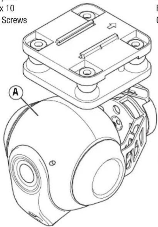
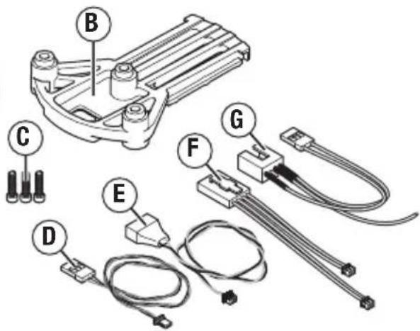
Box Contents
A. CG02 GB 3-Axis Camera/Gimbal
B. Mounting plate
C. (3) M2.5 x 10
Mounting Screws
D. 3-wire signal lead
E. 2-wire power lead
F. 4 pin Y-harness (not used)
G. 4-pin to servo harness (not used)
Technical Specifications
| Dimensions LxWxH (with lens): 3.00 x 101.62 x 129.12 mm | |
| Weight: 163 g | |
| Working Voltage: 12V | |
| Wireless Frequency Range: 5745MHz–5825MHz | |
| Lens Sensor: 16M | |
| Angle of view: 155° | |
| Controlled Rotation Range: Pitch Axis Control: –90°–0° | |
| Effective Pixels: 16 million | |
| White Balance: Automatic | |
| Focusing System: Fixed | |
| Storage Temperature: –20°–60°C | |
| Working Temperature: |
Loading the CGO2 App to Your WiFi Smart Device
- Download the free CGO2 GB App to your smartphone or tablet at the iTunes App Store or Google Play Store.
• Install the app to your 5.8GHz WiFi capable device. - Make a note of the network name and password key located on the top of the gimbal assembly.
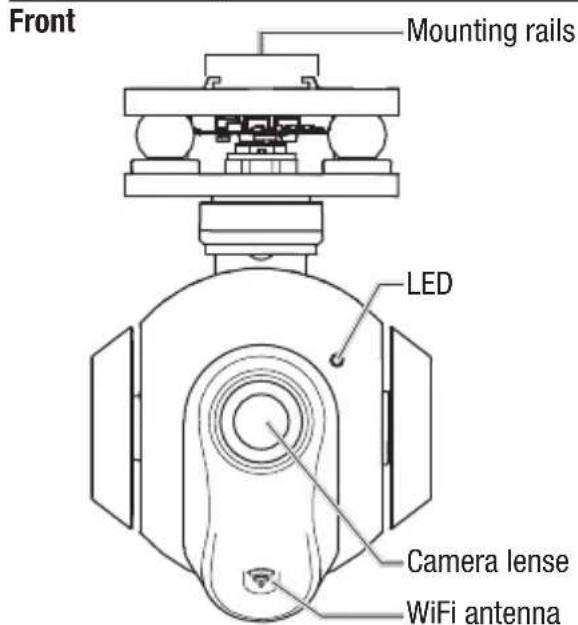
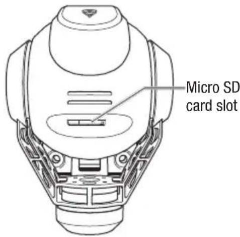
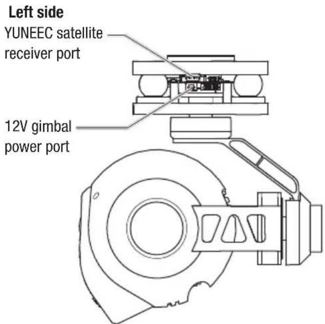
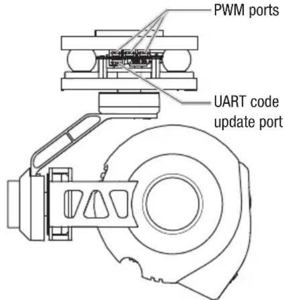
Gimbal Components
Bottom
Right side
EN
6
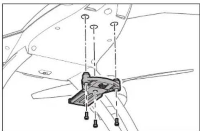
Installing the Mounting Plate
natural_image
Technical line drawing of a mechanical component with mounting holes and a central bracket (no text or symbols)Install the mounting plate using the 3 included M2.5 x 10 screws. Do not overtighten.
IMPORTANT: The CG02 GB requires the use of the Blade 350 QX2 body set and tall landing gear. If you wish to install the CG02 GB on a 350 QX, you must first install BLH7811A (body set) and BLH7815TGA (tall landing gear).
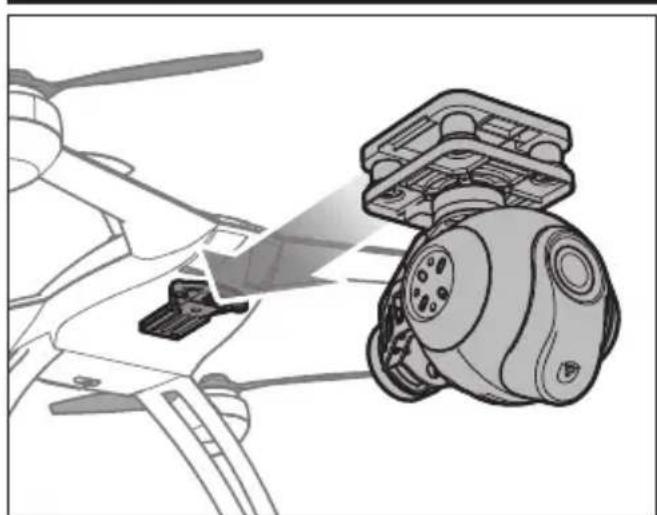
Installing the Gimbal
natural_image
Technical illustration of a mechanical assembly with a highlighted component (no text or symbols)Install the gimbal by lining up the tracks of the gimbal and the mount and pushing towards the rear of the plate until it locks into place as shown at left.
To remove the gimbal, push in the retaining clip at the front of the mounting plate and pull the gimbal forward.
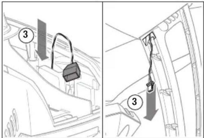
Routing the Wiring
There are two leads included with the CGO2 GB gimbal:
- 3-wire signal lead with a servo style connector and a 3-pin JST connector.
- 2-wire power lead with a 4-pin balance connector and a 2-pin JST connector.
Route the leads as follows:
- Plug the servo connector of the signal lead into the rearmost pins on the flight control board as shown at right, with the brown wire toward the outside.
- Route the JST connector through the hole in the landing gear mount on the bottom of the 350 QX.
- Route the JST connector of the power lead down through the hole in the opposite gear mount on the bottom of the 350 QX, leaving the balance connector loose inside the battery compartment.

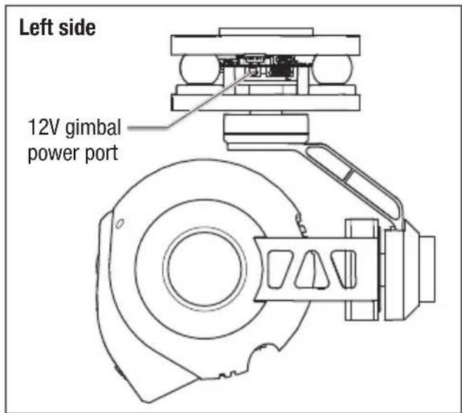
Connecting the Gimbal
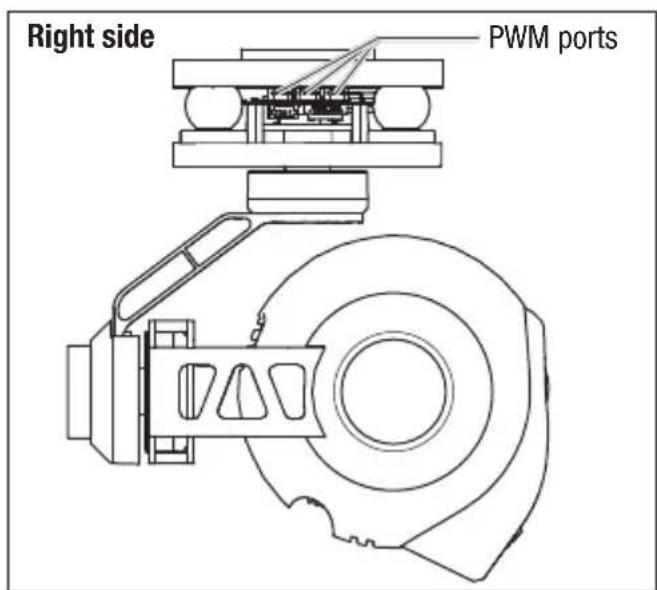
- Connect the signal lead to any of the 3 available PWM ports on the right side of the gimbal assembly.
- Connect the power lead to the 12V gimbal power port on the left side of the gimbal assembly.
Transmitter Programming
Transmitter control of the pitch angle of the CG02 GB is possible with most 6-channel and above Spektrum transmitters. Control of the pitch angle in flight is achieved on the DX6i and DX6 by temporarily using the throttle control stick to adjust pitch. If you are using the DX7s, DX8, DX9 or DX18, pitch control is achieved via the rotary knob on your transmitter.
To program your transmitter:
DX6i
- Set the Channel 6 (FLAP) Travel Adj. to 120 up and 100 down.
- Set the values in the FLAP menu to 100 up and 100 down.
To change gimbal angle BEFORE starting the motors for fl ight, set the fl ap switch to position 1. The throttle stick will now control the angle of the gimbal. Set the fl ap switch to position 0 before fl ight.
To change the gimbal angle IN FLIGHT, cycle the fl ap switch to position 1. The throttle stick will now control the gimbal angle for approximately 5 seconds before returning to throttle control. Return the fl ap switch to position 0.
DX6
In Channel Input Configuration:
- Assign channel 6 (AUX1) to switch A.
- Assign Gear to switch B.
In Servo Setup: - Reverse the travel for AUX1.
- Set the travel values for AUX1 to: 120% 140%
To change the gimbal angle BEFORE starting the motors for flight, set switch A to position 1. The throttle stick will now control the angle of the gimbal. Set switch A to position 0 before flight.
To change the gimbal angle IN FLIGHT, cycle switch A to position 1. The throttle stick will now control the gimbal angle for approximately 5 seconds before returning to throttle control. Return switch A to position 0.
DX7s
In Channel Input Configuration:
- Assign Channel 7 Input (AUX2) to the rotary knob.
- Assign AUX1 to the Gear switch.
In Servo Setup:
- Set the Channel 6 (AUX1) travel to the values below: 120% 140%
To change the gimbal angle, set the gear switch to position 0 and adjust the angle of the gimbal by rotating the knob on your transmitter at any time.
DX8
In Channel Input Configuration:
- Assign Channel 7 Input (AUX2) to the rotary knob.
- Assign AUX1 to the Gear switch.
In Servo Setup:
- Set the Channel 6 (AUX1) travel to the values below: 120 140
To change the gimbal angle, set the gear switch to position 0 and adjust the angle of the gimbal by rotating the knob on your transmitter at any time.
DX9, DX18
In Channel Input Configuration:
- Assign Channel 7 Input (AUX2) to R Knob.
- Assign AUX1 to A.
In Servo Setup:
- Set the AUX1 travel to the values below:
140
120
To change the gimbal angle, set switch A to position 0 and adjust the angle of the gimbal by rotating the R Knob at any time.
Using the Gimbal
- Insert the micro SD card into the slot on the bottom of the camera.
- Place the quadcopter on a flat and stable surface. Ensure there are no obstructions in the path of the CG02 GB.
- Switch on your transmitter.
- Plug the balance connector of the power lead into the balance lead of the quadcopter battery.
- Switch on your quadcopter.
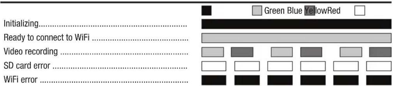
After the CGO2 GB powers on, the LED will glow red for approximately 40 seconds while the gimbal initializes. When the LED changes to green the CGO2 is ready to connect via WiFi.
See the “Using the CGO2 App” section for instructions on how to connect your gimbal to your smart device and for a description of the camera controls available. The gimbal will now compensate for any roll, pitch and yaw movements encountered by your quadcopter in flight.
If desired, you may change the pitch angle of the gimbal at any time using your programmed transmitter controls.
Using the CGO2 App
- With the CGO2 GB powered on, open the Wi-Fi settings on your smartphone or tablet and connect to the CGO2 GB network (CGO2 GB_******) using the password "1234567890".
- Open the CGO2 GB App on your device.
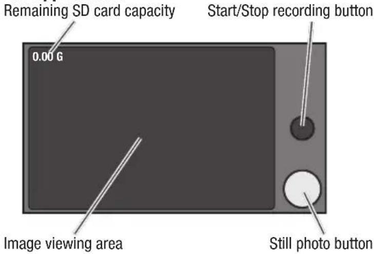
You can now take still photos or start/stop recording video by using the buttons shown at right.
It is possible to take still photos at any time, even while you are recording live video. Be sure to check for updates to the CG02 App in the iTunes App Store, or Google Play Store.
CGO App Controls
LED Codes
Troubleshooting
| Problem Possible Cause Solution | ||
| The gimbal vibrates after switching ON | Gimbal did not initialize correctly or was obstructed | Re-initialize with the gimbal clear of obstructions |
| Gimbal does not respond to control input | Gimbal did not initialize | Keep the quadcopter and gimbal level and immobile for 5 seconds after switching ON |
| Gimbal is not ON Incorrect gimbal connections Correctly connect gimbal | ||
| Gimbal does not respond to transmitter | Incorrect transmitter set up | Review transmitter programming section and make corrections to transmitter set up |
| Gimbal does not respond to control inputs. RED and BLUE LEDs are solid | Incorrect gimbal connections Correctly connect gimbal | |
| Gimbal is not ON and RED LED fl ashes slowly | Gimbal gyro board damage Contact Horizon Product Support | |
| Gimbal LED Flashing RED in Angle or Velocity Mode | Sensor Error | Check for correct gimbal connection or contact Horizon Product Support |
Replacement Parts
| Part # Description | |
| BLH8106 Mounting Hardware: C-Go2GB |
Optional Parts
| Part # Description | |
| BLH7811A Body Set with Hardware: 350 QX | |
| BLH7815TGA Tall Landing Gear Set: 350 QX2 AP |
Service Contact Information
| Country of Purchase | Horizon Hobby Contact Information Address | ||
| United States of America | Horizon Service Center (Repairs and Repair Requests) | servicecenter.horizonhobby.com/RequestForm/ | 4105 Fieldstone RdChampaign, Illinois, 61822 USA |
| Horizon Product Support (Product Technical Assistance) | www.quickbase.com/db/bghj7ey8c?a=GenNewRecord888-959-2304 | ||
| Sales | sales@horizonhobby.com888-959-2304 | ||
| United Kingdom | Service/Parts/Sales: Horizon Hobby Limited | sales@horizonhobby.co.uk Units+44 (0) 1279 641 097 | 1–4 , Ployters Rd, Staple TyeHarlow, Essex, CM18 7NS, United Kingdom |
| Germany | Horizon Technischer Service ser Sales: Horizon Hobby GmbH +49 (0) 4121 2655 100 | service@horizonhobby.de | |
| France | Service/Parts/Sales: Horizon Hobby SAS | infofrance@horizonhobby.com+33 (0) 1 60 18 34 90 | Christian-Junge-Straße 125337 Elmshorn, Germany |
| China | Service/Parts/Sales: Horizon Hobby – China | info@horizonhobby.com.cn+86 (021) 5180 9868 | Room 506, No. 97 Changshou Rd.Shanghai, China 200060 |

natural_image
Abstract geometric shape with black and white color blocks, no text or symbols present©2014 Horizon Hobby, LLC.
Blade is a registered trademarks of Horizon Hobby, LLC.
Yuneec is a trademark of Yuneec International Co., Ltd.
All other trademarks, service marks or logos are property of their respective owners.
Patents pending. Created 12/14 46791.1 BLH8110