CHAN1BA1 - Washing machine ITB - Free user manual and instructions
Find the device manual for free CHAN1BA1 ITB in PDF.

| Product Type | Freestanding Washing Machine |
| Brand | ITB |
| Model | CHAN1BA1 |
| Dimensions (H x W x D) | 85 cm x 60 cm x 55 cm |
| Weight | 65 kg |
| Power Supply | 220-240 V ~ 50 Hz |
| Energy Class | A+++ |
| Capacity (Wash) | 8 kg |
| Spin Speed | 1400 rpm |
| Wash Programs | Cotton, Synthetics, Delicates, Quick, Wool, Rinse & Spin, Drum Clean |
| Additional Functions | Delay Start, Child Lock, Auto Load Adjustment, Temperature Selection |
| Noise Level (Wash/Spin) | 54 dB / 74 dB |
| Water Consumption per Cycle | 48 L |
| Annual Energy Consumption | 220 kWh |
| Maintenance and Cleaning | Clean detergent drawer and filter regularly, run drum clean cycle |
| Safety Features | Overflow protection, child lock, door lock during operation |
| Spare Parts & Repairability | Spare parts available for 10 years; motor, drum, pump replaceable |
Frequently Asked Questions - CHAN1BA1 ITB
User questions about CHAN1BA1 ITB
0 question about this device. Answer the ones you know or ask your own.
Ask a new question about this device
Download the instructions for your Washing machine in PDF format for free! Find your manual CHAN1BA1 - ITB and take your electronic device back in hand. On this page are published all the documents necessary for the use of your device. CHAN1BA1 by ITB.
USER MANUAL CHAN1BA1 ITB
INSTALLATION INSTRUCTIONS
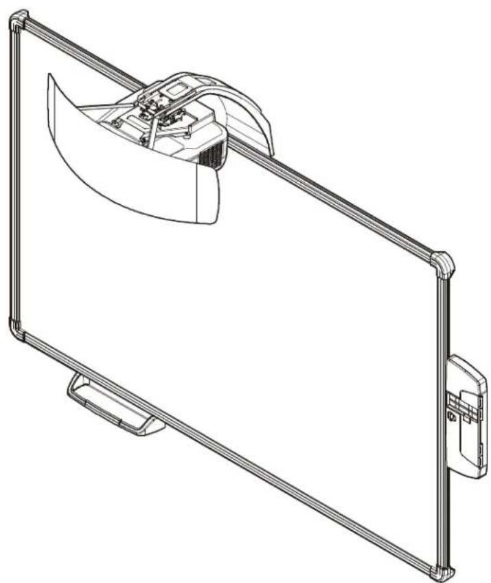
natural_image
Technical line drawing of a mechanical device with a curved component mounted on a metal frame (no text or symbols)All-in-One System
DISCLAIMER
Milestone AV Technologies and its affiliated corporations and subsidiaries (collectively "Milestone"), intend to make this manual accurate and complete. However, Milestone makes no claim that the information contained herein covers all details, conditions or variations, nor does it provide for every possible contingency in connection with the installation or use of this product. The information contained in this document is subject to change without notice or obligation of any kind. Milestone makes no representation of warranty, expressed or implied, regarding the information contained herein. Milestone assumes no responsibility for accuracy, completeness or sufficiency of the information contained in this document.
Chief® is a registered trademark of Milestone AV Technologies. All rights reserved.

IMPORTANT SAFETY INSTRUCTIONS

WARNING: A WARNING alerts you to the possibility of serious injury or death if you do not follow the instructions.

CAUTION: A CAUTION alerts you to the possibility of damage or destruction of equipment if you do not follow the corresponding instructions.

WARNING: Failure to read, thoroughly understand, and follow all instructions can result in serious personal injury, damage to equipment, or voiding of factory warranty! It is the installer's responsibility to make sure all components are properly assembled and installed using the instructions provided.

WARNING: Failure to provide adequate structural strength for this component can result in serious personal injury or damage to equipment! It is the installer's responsibility to make sure the structure to which this component is attached can support five times the combined weight of all equipment. Reinforce the structure as required before installing the component. The wall to which the mount is being attached may have a maximum drywall thickness of 5/8" (1.6cm) for wood and steel stud walls, and NO drywall on concrete walls.

WARNING: Use this mounting system only for its intended use as described in these instructions. Do not use attachments not recommended by the manufacturer.

WARNING: Never operate this mounting system if it is damaged. Return the mounting system to a service center for examination and repair.

WARNING: Do not use this product outdoors.
IMPORTANT ! : The AN1 Series mounts are designed to be used ONLY with the Epson BrightLink Pro 1410Wi projector.
IMPORTANT ! : The AN1 Series mounts are designed to be mounted to:
- an 8" concrete or 8"x8"x16" concrete block wall;
- a 2" x 4" wood studs (16" on center minimum) wall;
- a 2" x 4"-25ga minimum steel studs (16" on center minimum) wall.
--SAVE THESE INSTRUCTIONS--
DIMENSIONS
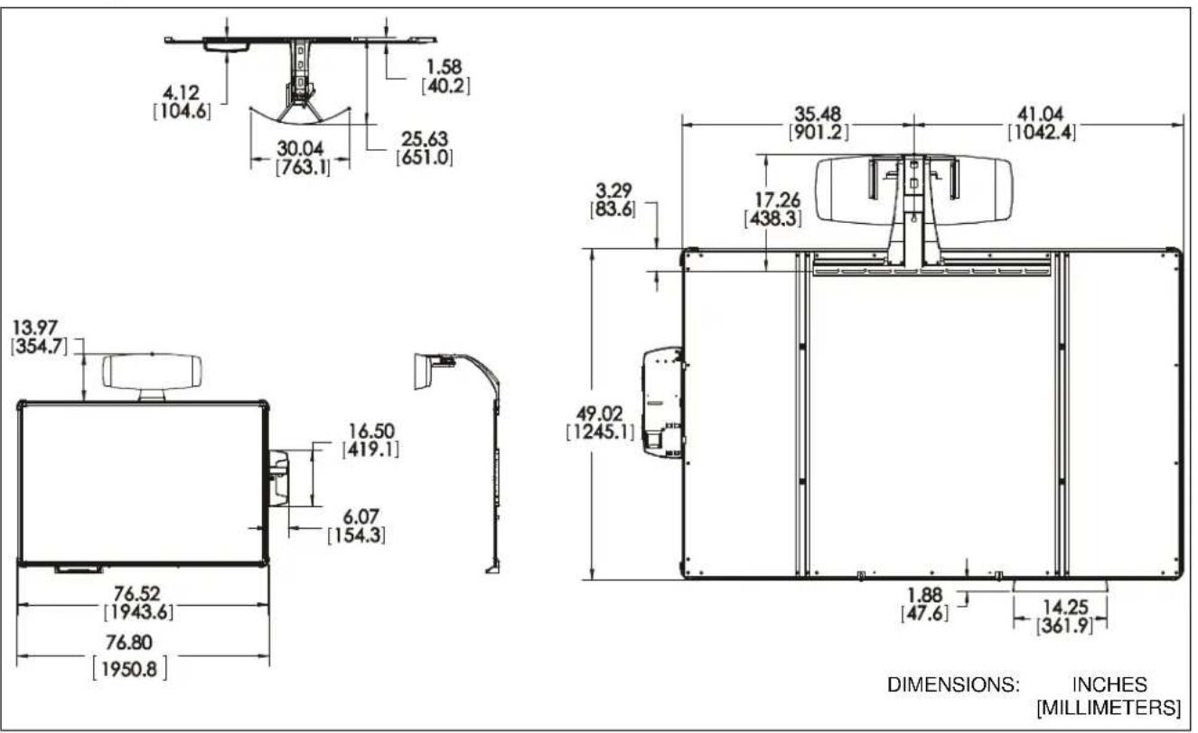
DIMENSIONS: INCHES [MILLIMETERS]
LEGEND
 | Tighten Fastener |  | Pencil Mark |
| Apretar elemento de fijación | Marcar con lápiz | ||
| Befestigungsteil festziehen | Stiftmarkierung | ||
| Apertar fixador | Marcar com lápis | ||
| Serrare il fissaggio | Segno a matita | ||
| Bevestiging vastdraaien | Potloodmerkteken | ||
| Serrez les fixations | Marquage au crayon | ||
 | Loosen Fastener |  | Drill Hole |
| Aflojar elemento de fijación | Perforar | ||
| Befestigungsteil lösen | Bohrloch | ||
| Desapertar fixador | Fazer furo | ||
| Allentare il fissaggio | Praticare un foro | ||
| Bevestiging losdraaien | Gat boren | ||
| Desserrez les fixations | Percez un trou | ||
 | Phillips Screwdriver |  | Adjust |
| Destornillador Phillips | Ajustar | ||
| Kreuzschlitzschraubendreher | Einstellen | ||
| Chave de fendas Phillips | Ajustar | ||
| Cacciavite a stella | Regolare | ||
| Kruiskopschroevendraaier | Afstellen | ||
| Tournevis à pointe cruciforme | Ajuster | ||
 | Open-Ended Wrench |  | Remove |
| Llave de boca | Quitar | ||
| Gabelschlüssel | Entfernen | ||
| Chave de bocas | Remover | ||
| Chiave a punte aperte | Rimuovere | ||
| Steeksleutel | Verwijderen | ||
| Clé à fourche | Retirez | ||
 | By Hand |  | Optional |
| A mano | Opcional | ||
| Von Hand | Optional | ||
| Com a mão | Opcional | ||
| A mano | Opzionale | ||
| Met de hand | Optie | ||
| À la main | En option | ||
 | Hex-Head Wrench |  | Security Wrench |
| Llave de cabeza hexagonal | Llave de seguridad | ||
| Sechskantschlüssel | Sicherheitsschlüssel | ||
| Chave de cabeça sextavada | Chave de segurança | ||
| Chiave esagonale | Chiave di sicurezza | ||
| Zeskantsleutel | Veiligheidssleutel | ||
| Clé à tête hexagonale | Clé de sécurité |
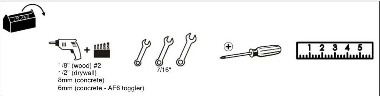
TOOLS REQUIRED FOR INSTALLATION
PARTS
![Install Hardware Kit A (4) 1/4 x 2-1/2" B (4) Hilti Hud-L #8 x 60 F (8) [4" cable tie] C (4) 1/4-20 x 1-3/4" D (4) 1/4" E (4) 1/4-20 [Toggler anchor kit] K (8) #8 x 1/2" G (4) 10-24 x 3/8" H (10) 10-24 x 3/8" J (4) M4 x 10mm L (6) #8-9 x 1-1/2" M (6) Toggler AF6 N (2) #4-24 x 1/4" P (6) [Screen bracket] R (1) [Wall bracket] S (1) [Projector interface] T (1) [Control panel assembly] Q (1) [Screen assembly] U (1) [Boom projector mount] V (1) [Marker set] X (1) [Left valence bracket] Y (1) [Right valence bracket] W (1) [Marker tray] Z (1) [RF Cable] AA (1) [Valence]](/content/2026/05/1143702/images/63077bfe2acce7623dee14454aad4e5ffefb1ea760b72c19f614b9f576510a39.jpg)
INSTALLATION
Determining Location
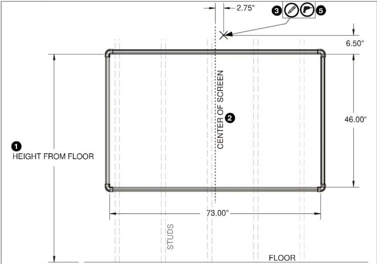
Figure 1
- Determine desired height of screen (measured from floor). (See Figure 1)
- Determine desired center of screen. (See Figure 1)
- Measure 6.5 inches up from desired height (top) of screen and 2.75 inches to the right of center of screen and mark location. (See Figure 1)
- Determine location of studs behind drywall.
- Drill one pilot hole (see Table 1 for size) at location marked in Step 3 (See Figure 1) and follow fastener information (appropriate for wall type) located in Table 1.
IMPORTANT ! : See Fastener Installation Methods at end of Installation Instructions for details on installing product into various wall types.
Table 1: Fastener Information
| WALL TYPE PILOT HOLE | FASTENERS (see PARTS drawing) | |
| Drywall only- (boom attach only) / Steel studs | 1/2" 1/4-20 | Toggler anchor kit (C, D, E)- 1/4-20 x 1-3/4" Phillips screw (C)- 1/4" washer (D)- 1/4-20 Snap toggler (E) |
| Wood stud | 1/8" 1/4 x 2 | -1/2" hex head lag (A) |
| Concrete | 8mm x 80mm | 1/4 x 2-1/2" hex head lag (A)Hilti Hud-L #8x60 anchor (B) |
| (Only for installing screen bracket into concrete)6mm x 45mm | #8-9x1-1/2" Phillips screw(L) Toggler AF6 (M) | |
Installing Wall Bracket / Boom Projector Mount
- Install one fastener (See Table 1) into previously drilled hole, leaving 1/2" of fastener extending from wall. (See Figure 2)
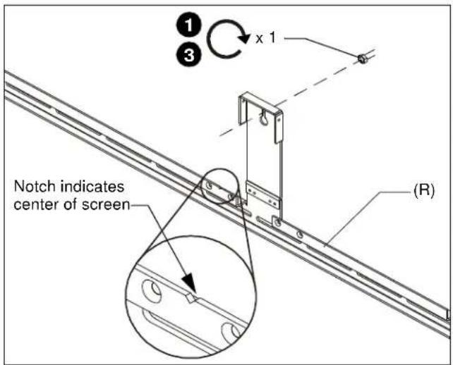
Figure 2
- Hang wall bracket (R) onto fastener.
NOTE: Notch in wall bracket (R) indicates center of screen. (See Figure 2)
- Tighten fastener against wall bracket.
- Lower boom projector mount (U) onto wall bracket (R) matching two fastener holes in upper arm with holes in upper wall bracket. (See Figure 3)
- Align four fastener holes along bottom of boom projector mount with four holes in wall bracket. (See Figure 3)
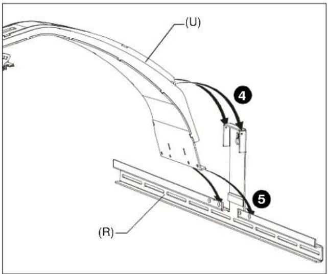
Figure 3
- Install and tighten two 10-24 x 3/8" Phillips cap head screws (H) through upper arm of boom projector mount (U) into vertical portion of wall bracket (R). (See Figure 4)
- Install and tighten four 10-24 x 3/8" Phillips flat head screws (G) through wall bracket (R) into boom projector arm (U). (See Figure 4)
- Determine location of studs behind drywall, and mark a minimum of two locations for wall bracket attachment over studs.
NOTE: For concrete walls, mark at least two locations for attachment a minimum of 16" apart AND within slots on wall bracket (R). - Drill one pilot hole (see Table 1 for size) at each location marked in Step 8 (See Figure 4) and follow fastener information (appropriate for wall type) located in Table 1.
NOTE: Proceed to Fastener Installation Methods section at end of Installation Instructions. - Fasten wall bracket assembly to wall using fasteners appropriate to wall type (See Table 1). (See Figure 4)
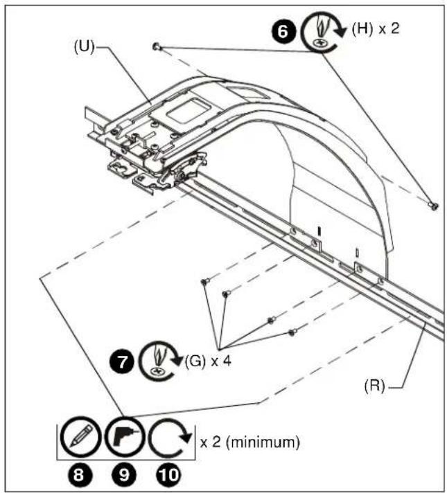
Figure 4
Attaching Screen
- Hang screen assembly (Q) onto wall bracket (R) using pre-installed bracket on back of screen assembly. (See Figure 5)
- Center screen assembly on wall bracket, matching pieces of tape on top of screen with edges of boom mount on wall bracket.
NOTE: Notch in wall bracket (R) indicates center of screen. (See Figure 2)
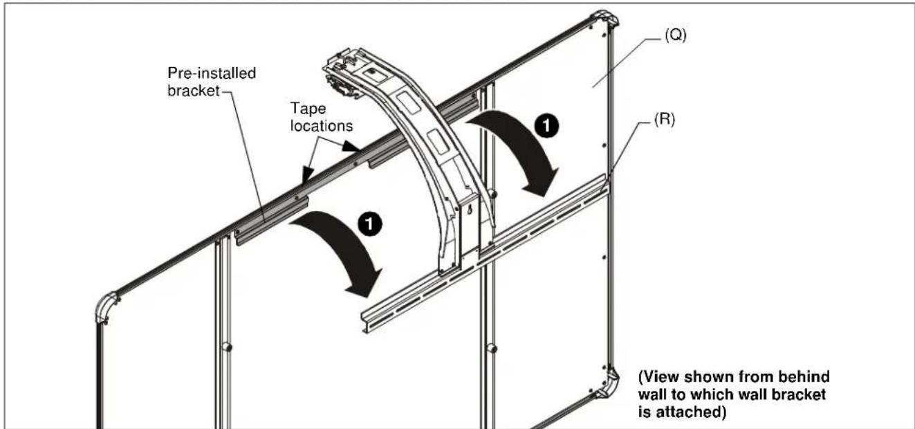
Figure 5
- Using screen brackets (P) as a template, locate studs, slide bracket up under screen, and trace line under brackets at locations on studs or on concrete wall. (See Figure 6)
NOTE: Use 3 screen brackets (minimum of 2 brackets) along bottom of screen, and locate brackets as close to outer corners as possible. Remaining brackets may be used along sides of screen, as desired.
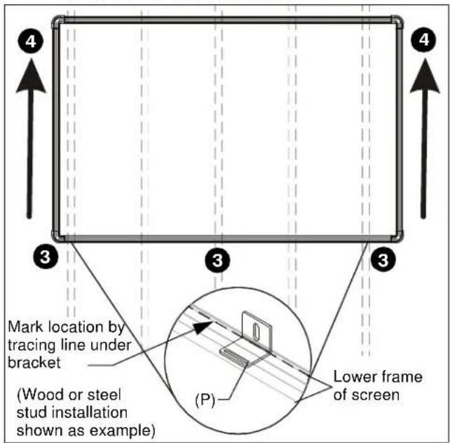
Figure 6
- Lift and remove screen from wall bracket.
- Install screen brackets (P) using:
- Wood/steel studs: one #8-9 x 1-1/2" wood screw (L) into top of each bracket slot and slightly lower than marked location. (See Figure 6)
- Concrete wall: one #8-9 x 1-1/2" wood screw (L) into top of each bracket slot and slightly lower than marked location, and into installed AF6 toggler. (See Figure 6)
- Replace screen onto wall bracket.
- Slide screen brackets (P) up on wood screw and fasten to screen frame using one #8 x 1/2" self-drilling screw (K) per screen bracket (P). (See Figure 7)
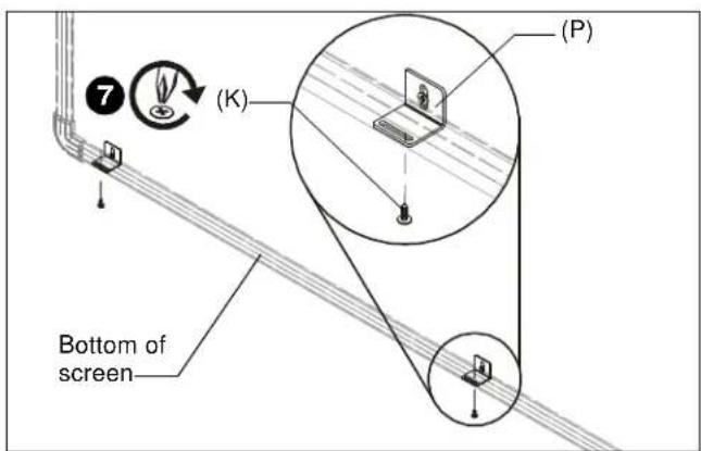
Figure 7
Installing Projector
- Attach projector interface (S) to projector using four M4 x 10mm Phillips cap head screws (J). (See Figure 8)
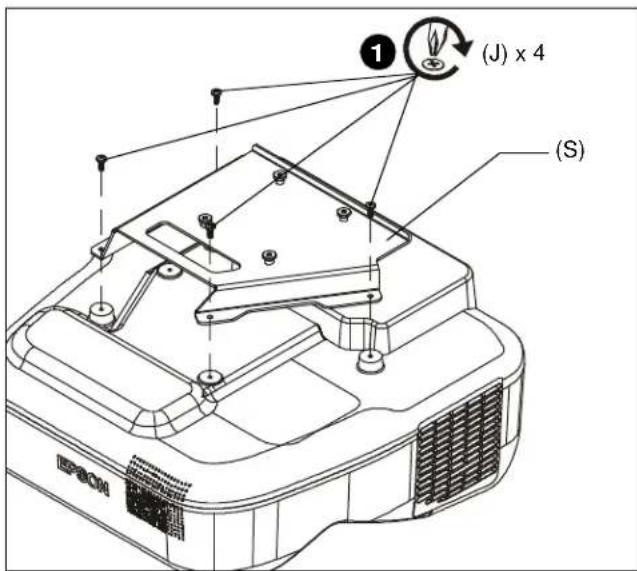
Figure 8
- Lift projector with attached interface (S) and slide buttons on interface into slots on boom projector mount (U). (See Figure 9)
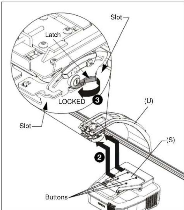
Figure 9
- Slide latch to LOCKED position to lock projector in place. (See Figure 9)
Installing Control Housing
- Open door on control panel assembly (T).
- Insert edges of control panel assembly (T) into groove in screen frame, with tab placed behind screen. (See Figure 10)
- Slide control panel assembly up along side of screen assembly to the desired height. (See Figure 10)
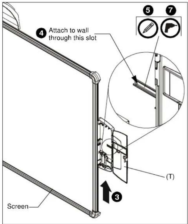
Figure 10
- Determine attachment location on wall. (See Figure 10)
- Mark attachment hole through slot in control panel assembly (T). (See Figure 10)
- Slide control panel assembly up or down, away from marked hole.
- Drill one pilot hole (see Table 1 for size) at location marked in Step 5 (See Figure 10) and follow fastener information (appropriate for wall type) located in Table 1.
- Proceed to Fastener Installation Methods section at end of Installation Instructions.
Installing Control Pad
- Remove top cover from control pad. (See Figure 11)
- Open lower cover on control pad. (See Figure 11)
- Insert control pad into control housing (T) by sliding it up under tabs inside housing. (See Figure 11)
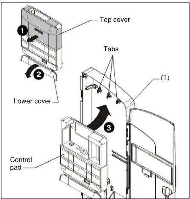
Figure 11
- Align holes in control pad with bosses in control housing and push control pad into place. (See Figure 12)
- Secure control pad into place using two #4-24 x 1/4" Phillips pan head screws (N). Do NOT overtighten. (See Figure 12)
- Attach all cables, including RF cable (Z), to control pad following instructions included with projector/control pad.
IMPORTANT ! : Connect cables BEFORE replacing control pad cover.
-
Use cable ties (F), as necessary, to secure the cables within control panel. (See Figure 12)
-
Replace top cover onto control pad. (See Figure 12)
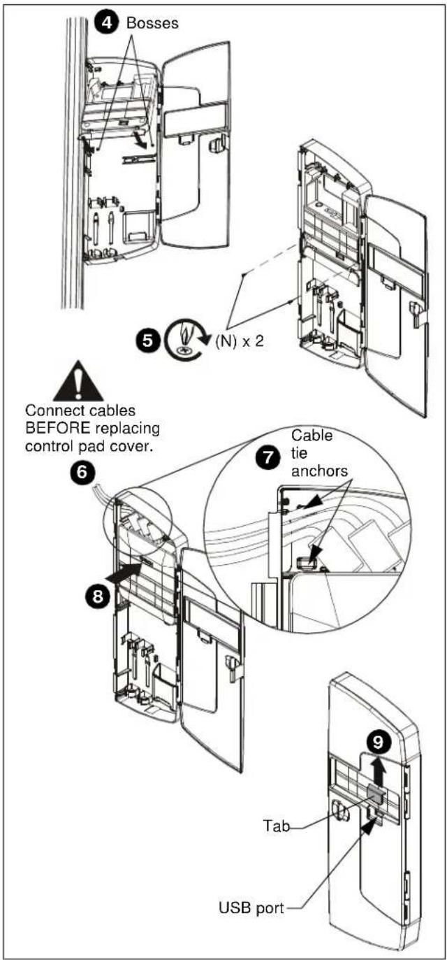
Figure 12
- OPTIONAL: The tab in the control panel assembly door may be removed to allow attachment to the USB port. (See Figure 12)
Projector Adjustments
Yaw Adjustment
- Loosen yaw adjustment locking screw using a #2 Phillips screwdriver. (See Figure 13)
- Turn yaw micro-adjustment screw right or left using a #2 Phillips screwdriver until image is properly aligned on target.
- Tighten yaw adjustment locking screw using a #2 Phillips screwdriver. (See Figure 13)
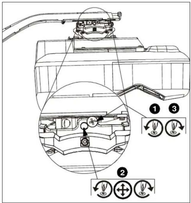
Figure 13
Pitch Adjustment
- Loosen pitch adjustment locking screw using a #2 Phillips screwdriver. (See Figure 14)
- Turn pitch micro-adjustment screw right or left using a #2 Phillips screwdriver until image is properly aligned on target.
- Tighten pitch adjustment locking screw using a #2 Phillips screwdriver.
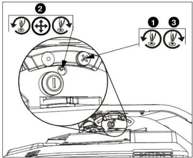
Figure 14
Roll Adjustment
- Loosen roll adjustment locking screw using a #2 Phillips screwdriver. (See Figure 15)
- Turn roll micro-adjustment screw right or left using a #2 Phillips screwdriver until image is properly aligned on target.
- Tighten roll adjustment locking screw using a #2 Phillips screwdriver.
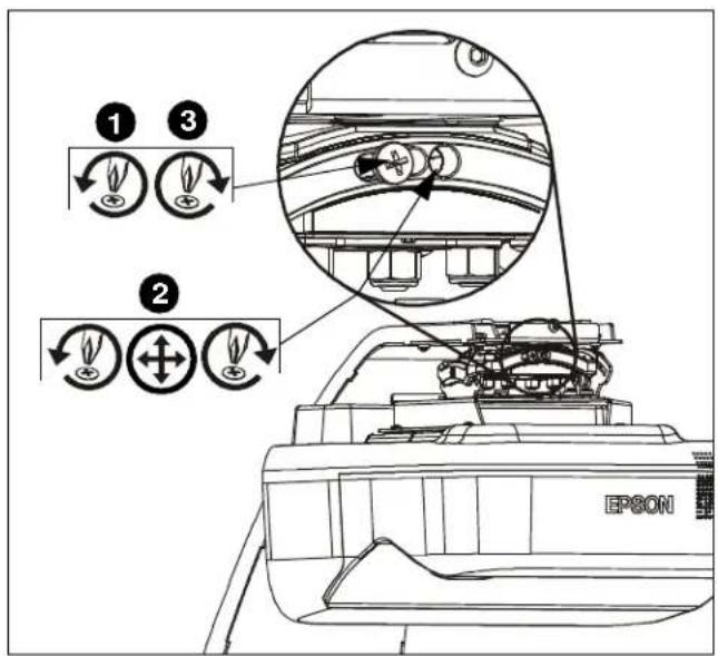
Figure 15
Micro Adjustment
- If required, turn the micro adjust fastener clockwise to extend projector further from wall. (See Figure 16)
- If required, turn the micro adjust fastener counterclockwise to retract projector closer to wall.
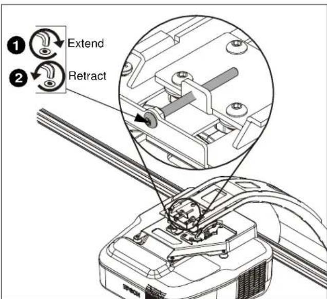
Figure 16
Attaching Marker Tray
- Attach marker tray (W) at any point along bottom of screen frame using two #8 x 1/2" self-drilling screws (K). (See Figure 17)
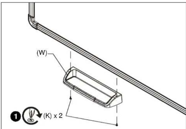
Figure 17
Attaching Valence
- Align right valence bracket (Y) along outside of right brace on back of valence (AA), and fasten with two 10-24 x 3/8" Phillips pan head machine screws (H). (See Figure 18)
- Align left valence bracket (X) along outside of left brace on back of valence (AA), and fasten with two 10-24 x 3/8" Phillips pan head machine screws (H). (See Figure 18)
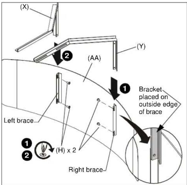
Figure 18
- Slide the valence (AA) with attached brackets into the boom mount (U), sliding brackets under tabs in boom. (See Figure 19)
- Adjust distance as required.
- Fasten through bracket slots into boom mount using four 10-24 x 3/8" Phillips pan head machine screws (H). (See Figure 19)
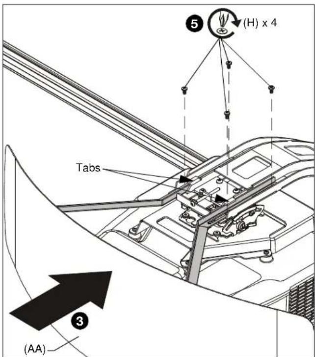
Figure 19
FASTENER INSTALLATION METHODS
NOTE: Refer to Table 1 for appropriate hardware and pilot hole sizes for various wall types.
Steel Stud / Drywall
- Hold metal channel on anchor (E) flat alongside plastic straps and slide channel through hole. (See Figure 20)
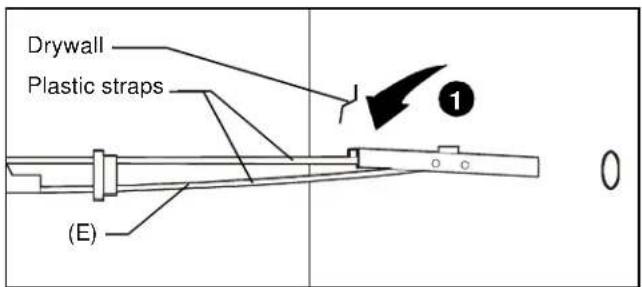
Figure 20
- Holding plastic straps on anchor (E), pull anchor away from wall until channel rests flush behind wall making sure anchor channel is positioned vertically on drywall, or steel stud (if present). (See Figure 21)
- Slide plastic cap on anchor (E) towards wall until flange of cap is flush with wall. (See Figure 21)
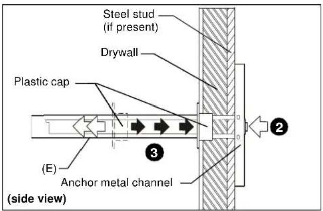
Figure 21
- Snap off plastic straps on anchor at wall by pushing side to side, snapping off straps level with flange of plastic cap. (See Figure 22)
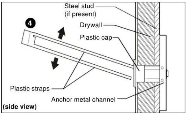
Figure 22
- Line up anchor with attachment point.
- Insert 1/4-20 x 1-3/4" Phillips pan head screw (C) through 1/4" washer (D), corresponding mounting hole in product and into anchor (E), and tighten until flush against product. DO NOT overtighten! (See Figure 23)
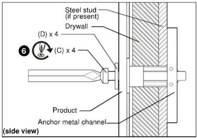
Figure 23
Wood Stud
NOTE: Refer to Table 1 for appropriate hardware and pilot hole sizes for various wall types.
- Use one 1/4 x 2-1/2" lag bolt through product and into pilot hole. (See Figure 24)
- Repeat for remaining pilot hole.
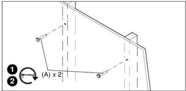
Figure 24
Concrete
NOTE: Refer to Table 1 for appropriate hardware and pilot hole sizes for various wall types.
- Install an anchor (B) into each pilot hole using a hammer, making sure that the anchor is flush with the wall.
- Use one 1/4 x 2-1/2" lag bolt (A) through product into each anchor in wall.
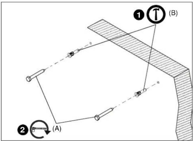
Figure 25
AN1 Series
Installation Instructions