IPS 310 CI - Media player Fte maximal - Free user manual and instructions
Find the device manual for free IPS 310 CI Fte maximal in PDF.

User questions about IPS 310 CI Fte maximal
0 question about this device. Answer the ones you know or ask your own.
Ask a new question about this device
Download the instructions for your Media player in PDF format for free! Find your manual IPS 310 CI - Fte maximal and take your electronic device back in hand. On this page are published all the documents necessary for the use of your device. IPS 310 CI by Fte maximal.
USER MANUAL IPS 310 CI Fte maximal
- Initial installation....2
1.1. Safety measures....2
1.2. Box content....2
1.3. Description and connections....3
1.4. IPLanTVManager Installation user's guide....3
1.5. First connection of the modules....4
1.6. Accessories and examples of installations....6
1.6.1. Accessories....6
1.6.2. Examples of installation....7
- DVB-IP 8
2.1. Operation Modes 8
2.1.1. SPTS Mode 8
2.1.2. MPTS Mode 8
2.2. Searching devices....9
2.3. Management Tasks....11
2.3.1. Configuration of the device parameters....11
2.3.2. Configuration of the LNB parameters (DVB-S / DVB-S2)....12
2.3.3. Firmware Update....13
2.3.4. Initialization 13
2.3.5. Suspend and Resume 13
2.3.6. Management of the slots "Common Interface" (-CI)....13
2.3.7. Events Logging....13
2.4. Configuration....13
2.4.1. Streaming Mode 14
2.4.2. Search for the available services/frequencies....14
2.4.2.1. Manual search in DVB-S, DVB-S2, DVB-T and DVB-C devices....15
2.4.2.2. Automatic search in DVB-S, DVB-S2, DVB-T and DVB-C devices....16
2.4.2.3. Service/Frequency list....18
2.4.3. Definition of the streaming services....21
2.4.3.1. Definition of a streaming service from an existing service/transponder in database 22
2.4.3.2. Definition of a streaming service from an existing streaming service (SPTS)....22
2.4.3.3. Definition of a streaming service with no previous service reference (SPTS)....22
2.4.4. Start and stop a streaming service....25
2.4.5. Configuration of DVB-S/DVB-S2 devices sharing the same antenna....25
2.4.6. Configuration of services in devices with "Common Interface" option....26
- Technical features....27
- Declaration of conformity....29

This user's guide is adapted to the software version v.7.8.10 of IP LAN TV Manager and the software version 3.6.5.18_1 of the module.
For future software updates, you will be able to download the software and the user's guide in the following website: http://www.ftemaximal.com
1. Initial installation
1.1. Safety measures
Please read carefully these safety rules before installing your device.
1.- Never place the device next to hot sources.
2.- Never undergo the device to temperatures that exceed its level of operation.
3.- Never expose the device to leakings nor spatterings.
4.- Never place objects that contain liquids over the device.
5.- Respect the ventilation slots of the device, do not cover them with any kind of object.
6.- The space around the device must be free of objects, in a minimum radius of 40cm.
7.- Avoid locations with possibilities of spilling liquids on the inside of the device, and with important changes of temperature.
8.- Never open the device by yourself due to electric risk. In case of problems, go always to qualified technicians
9.- Never, under no circumstances, open the device when connected to the electrical net..
10.- During the handling it is better to disconnect the device from the electrical net.
11.- Obey the electricity security rules during the assembling. Use materials that obey the current law.
12.- The connecting plug must be accessible in a fast and simple way to have a fast disconnection.
13.- Never touch the plug with wet hands. Also, disconnect always the device before handling the connections.
14.- Never put any heavy object over the device, since it could get damaged.
15.- If the device is going to remain some time without use, it is recommendable to disconnect it from the electrical net.
16.- The repairmen and the maintenance of the device must be done by TV and radio specialised technicians
1.2. Box content


IP receiver module User's guide Feeding cable Rigid bridge
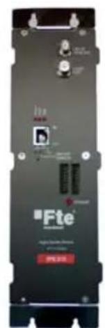
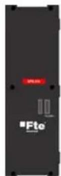
1.3. Description and connections
There are several models of IP headends FTE Maximal:
- IPS 310, IPS 310 Cl: for the reception of satellite digital signal (DVB-S y DVB-S2).
- IPT 310, IPT 310 CI: for the reception of terrestrial digital signal (DVB-T).
- IPQ 310, IPQ 310 CI: for the reception of cable digital signal (DVB-C).
The input signal is connected in the IN input of the module. If you want to send the input signal to another module, the LOOP OUT output has to be connected to the in INPUT of the following module, by the means of bridges or cable.
The output of the IPTV signal is connected to the IP net of the installation by the means of the RJ-45 output.
The feeding cable between each module has to be twisted in order to minimize the radiation effects of the modules.
CI (Common Interface) models are provided with slots for connecting 2 CI modules.
1.4. IPLanTVManager Installation user's guide
To run IPLanTVManager it is recommended the following minimum hardware features:
- Pentium 4 (2GHz) and 512 MB RAM
- Ethernet Interface
- 200 MB free on Hard Disk
- OS installed: Windows 2K / XP (Service pack 2 or higher) / Vista
1.- Unzip file and run "IPLanTVManager_setup_vx.x.x.exe" for installing application:
2.- After installing, run application IPLanTVManager at PC desktop. The first time the application is run, you will see the window alert:
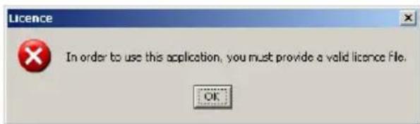
3.- Then, application will start:
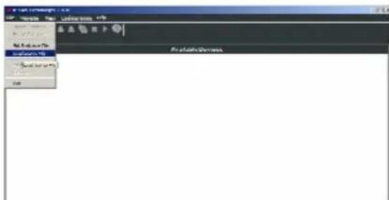
4.- At this point, you must install the license of the program. Access to menu file → Load Licence File.
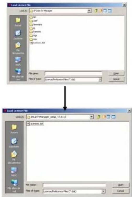
5.- By default, program will select a null file (pre-licence) included with the installation, but you must select the licence file included in .zip downloaded:
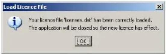
6.- After selecting new licence, new alert will be shown on screen and application will be closed when press OK.
7.- IPLanTVManager is ready for being used.
1.5. First connection of the modules

IMPORTANT:
All the modules go out of factory with the same IP address by default: 192.168.4.121.
You must make the connection and IP configuration of all the modules one by one. All the modules must have different IP addresses.
Follow the next steps in order to connect the IP modules:
- PC preparation: In order to manage the modules, you need to have a PC connected in the same net, and it has to have the IP LAN TV Manager application installed.
- Configure the IP address of the PC in the same net where the module is. To do so, follow the next steps:
- For Windows XP:
Access to the net configuration pressing Start menu • Control Panel • Net connections.
Press the right button of the Mouse over the local area connection icon and select Properties. In the General tab select in internet protocol list TCP/IP and press Propertiesbutton.
A configuring window of the IP net will appear.
- For Windows Vista:
Access to the net configuration pressing Start Menu • Control Panel • Net centre and shared resources • Manage net connections.
Press the right button of the Mouse over the local area connection icon and select Properties Select in the Internet protocol version 4 list (TCP/IP v4) and press Properties button.
A configuring window of the IP net will appear.
Once you have reached the IP configuring window, modify the following fields:
IP address: It must have a value that has to be in the same net as the IP address by default of the modules: 192.168.4.x (x: any value between 1 and 255)
Subnet mask Must have the value 255.255.255.0
Predetermined gateway. It must have a value within the same IP net as the one where the module is. Normally 192.168.4.1
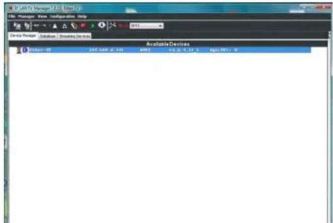
- Run IP LAN TV Manager application with the PC ready and connected to the IP net. The connected module will appear in the devices list.
- Over the module, press the right button and select Connect. A new icon will appear beside the connected module:
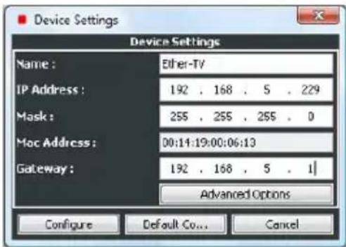
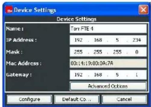
- Access to the configuration of the module pressing Configuration • Device Settings Introduce here the following parameters:
- IP Address: Introduce in this field the definitive IP address that you wish for the module to have inside its net. Remember that it is important that the IP address of the modules has to belong to the same net as its installation, and that each module and devices must have different IP addresses in order to avoid conflicts.
- Mask: Introduce the value 255.255.255.0
- Gateway: This is the link port. This value is the same for all the modules and its value must be within its net.
- Inside this window, press over Advanced Options and configure the TTL. This parameter defines the quantity of switch's/routers where a set sent from a module can go through. It gives us and idea about how big our IP net is.
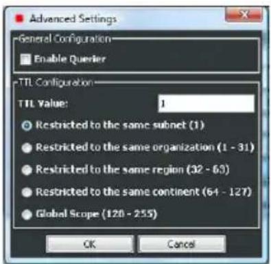
- Once the TTL is configured, press OK. Then press Configure and OK in the message that will appear after.
Repeat the steps of the configuration in each module from IP LAN TV Manager, connecting them one by one. Once you have finished, for futures modifications, remember that the PC where the IP LAN TV Manager is installed must have the IP address in the same net as the headend.
1.6. Accessories and examples of installations
1.6.1. Accessories

natural_image
Simple line drawing of a rectangular frame with no text or symbolsChassis for 7 modules 310 series Mod. FRA 300 Cod. 2003304

natural_image
Metal L-shaped bracket with bolt holes and mounting holes (no text or symbols)Chassis 6 mod. 310 series for RACK Mod. CHR 300 Cod. 2003306
Power supply for FRA chassis Mod. SPS 310 Cod. 2003504
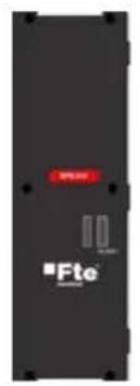
Power supply for RACK Mod. SPS 310 R Cod. 2003506
natural_image
Blue wired network cable with two connectors (no text or symbols visible)Patch cord cat.6 shielded 5m Mod. PC-6-F-MT-5BL Cod. 2220128
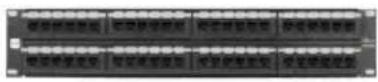
Patch Panel 19" 48 ports
Mod. PPC-6-U-48 Cod. 2220290
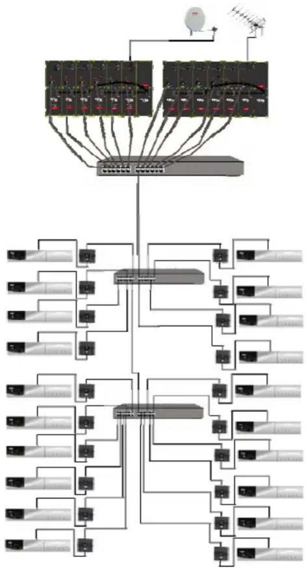
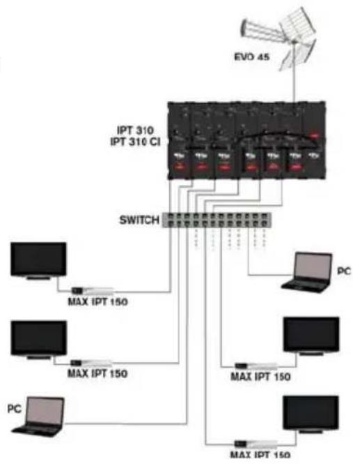
1.6.2. Examples of installation
In this example we can see a headend with IPT 310 and IPT 310 CI modules, that receive terrestrial signal and turn it into IP TV signal. The outputs of each module are connected to the ports of a switch for its distribution in the whole IP net.
flowchart
graph TD
    A["Central Hub"] --> B["Client Rack 1"]
    A --> C["Client Rack 2"]
    B --> D["Client Rack 3"]
    C --> E["Client Rack 4"]
    D --> F["Satellite Dish"]
    E --> G["Satellite Dish"]
    F --> H["Satellite Dish"]
    G --> I["Satellite Dish"]
    H --> J["Satellite Dish"]
    I --> K["Satellite Dish"]
    J --> L["Satellite Dish"]
    K --> M["Satellite Dish"]
    L --> N["Satellite Dish"]
    M --> O["Satellite Dish"]
    N --> P["Satellite Dish"]
    O --> Q["Satellite Dish"]
    P --> R["Satellite Dish"]
flowchart
graph TD
    PC["PC"] -->|MAX IPT 150| Switch["Switch"]
    Switch -->|IPT 310| I/O["O/U"]
    Switch -->|IPT 310 CI| I/O
    Switch -->|EVO 45| EVO["EO/45"]
    Switch -->|MAX IPT 150| PC
    Switch -->|MAX IPT 150| PC
    Switch -->|MAX IPT 150| PC
    Switch -->|MAX IPT 150| PC
    Switch -->|MAX IPT 150| PC
    Switch -->|MAX IPT 150| PC
    Switch -->|MAX IPT 150| PC
    Switch -->|MAX IPT 150| PC
    Switch -->|MAX IPT 1.50| PC
    Switch -->|MAX IPT 1.50| PC
    Switch -->|MAX IPT 1.50| PC
    Switch -->|MAX IPT 1.50| PC
    Switch -->|MAX IPT 1.50| PC
    Switch -->|MAX IPT 1.50| PC
    Switch -->|MAX IPT 1.50| PC
    Switch -->|MAX IPT 1.5 | PC
    Switch -->|MAX IPT 1.5 | PC
    Switch -->|MAX IPT 1.5 | PC
    Switch -->|MAX IPT 1.5 | PC
    Switch -->|MAX IPT 1.5 | PC
    Switch -->|MAX IPT 1.5 | PC
    Switch -->|MAX IPT 1.5 | PC
    Switch -->|MAX IPT 1.5 | PC
    Switch -->|MAX IPT.1.5 | PC
    Switch -->|MAX IPT.1.5 | PC
    Switch -->|MAX IPT.1.5 | PC
    Switch -->|MAX IPT.1.5 | PC
    Switch -->|MAX IPT.1.5 | PC
    Switch -->|MAX IPT.1.5 | PC
    Switch -->|MAX IPT.1.5 | PC
In this example we can see a headend with IPT 310 and IPS 310 modules, that receive terrestrial and satellite signal, and turn it into IP TV signal.
2. DVB-IP
IP LAN TV Manager is an application that allows the search, monitoring and configuration of the IP LAN TV devices grouped under the category of DVB-IP. Inside this category the following types of devices are found:
- IPS 310 (DVB-S / DVB-S2)
- IPT 310 (DVB-T)
- IPQ 310 (DVB-C)
The only difference among these types is the input stage of the device: for the three first types, satellite, terrestrial and cable, there is a module tuning/demodulator, different for each type, that treats the input RF signal coming from an antenna or modulator.
There is an additional hardware version for each of these devices, named "Common Interface" (CI) that allows to descramble encrypted services using up to two conditional access modules (CAM) via PCMCIA interface.
Using IP LAN TV Manager on these devices, we will be able to carry out some management configuration of the streaming services.
The management tasks are:
- Device settings configuration. These settings are the name, network settings, querying status and TTL.
- LNB settings configuration (only in case of DVB-S).
- Update of the firmware embedded on the device.
- Reset of the device, keeping its previous configuration.
- Suspend and resume the streaming coming out from the device.
The configuration of a device will consist basically in the election of the operation mode as well as of the services or programs that the device will serve to the network in format of "transport stream" encapsulated in IP, utilizing addressing multicast or unicast. These services must be in the same transponder or channel, because a device, in a given moment, only can tune in a single transponder.
On SPTS mode (see following paragraph), using this tool, we will be able to modify the services configured, changing the direction/port of streaming or adding or removing PIDs. Normally a service will consist of an set of PIDs: a video PID, one or various audio PIDs and perhaps some data PIDs..
2.1. Operation Modes
The device operation mode refers to the filter type that device applies on the input transport stream, and therefore to the content sent via Ethernet. The device can operate basically in two operation modes, SPTS mode (Single Program Transport Stream) and MPTS mode (Multiple Program Transport Stream). By default, the device will work on SPTS mode, and the change of mode is carried out by means of the menu options "Configuration/Set MPTS Mode" and "Configuration/Set SPTS Mode".
2.1.1. SPTS Mode
In the SPTS mode (Single Program Transport Stream), the device filters part of the information of the input transport stream. The filtered information is configured in SPTS services (up to eight as maximum) and encapsulated in IP according to each service streaming configuration. Normally, the SPTS services present a variable bitrate, and in order to create them, we will start from a list of available services.
2.1.2. MPTS Mode
In the MPTS mode (Multiple Program Transport Stream), the device filters all the information of the input transport stream. All this information is configured in a single service MPTS and encapsulated in IP according to its streaming configuration. Normally, the MPTS service present a constant bitrate, the same as the input transport stream. In this mode the device acts in a transparent way.
In this case, in order to configure the unique service, we will start from a list of available transponders.
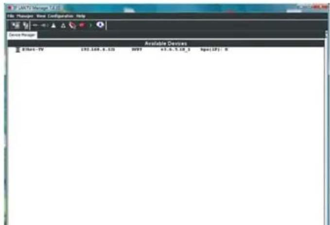
2.2. Searching devices
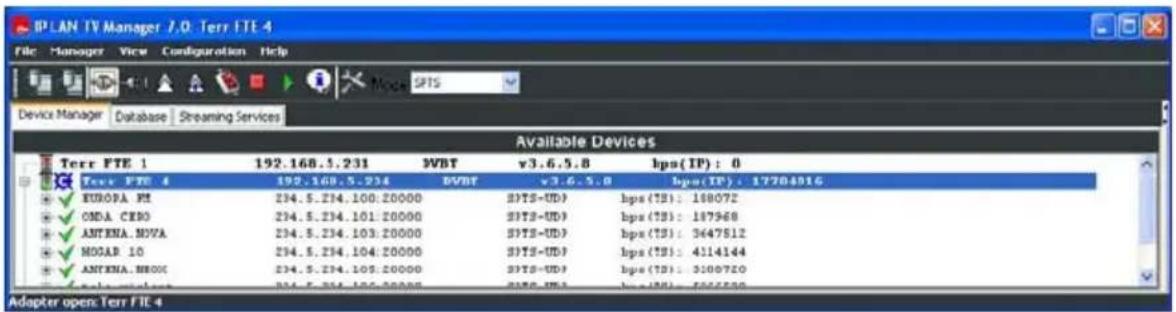
The search for the DVB-IP existing in the local network is automatic. The application continuously shows an updated list of devices in the local network, indicating their status. The DVB-IP devices present the text DVB-S, DVB-S2, DVB-T or DVB-C next to IP address. In case of devices that incorporate the hardware option "Common Interface" the text include the suffix -Cl.
This information is presented in "Device Manager" tab, and can be seen in the following figure.
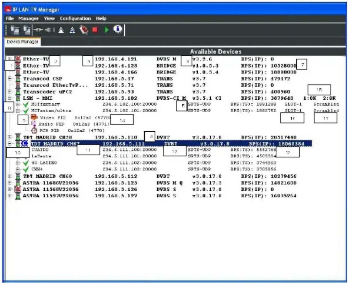
The information showed for every device is the following:
-
Device Status. The meaning of the possible values are:
-
Green light: the device is streaming out at least one service.
- Red light: the device is not streaming out any service.
- Crossed antenna: the device is not tuned, either it has not been previously tuned, or is not receiving RF signal from the antenna/modulator.
- Yellow light: temporary status, in which the device is initializing.
- No symbol (Board OFF): the device becomes not present (temporal status).
-
Question mark: the device has been manually connected.
-
Device Name.
- Device IP address.
- IP LAN TV device type that in case of DVB-IP devices can be the following values:
- DVB-S / DVB-S2: IPS 310.
- DVB-T: IPT 310.
- DVB-C: IPQ 310.
In case of devices that incorporate the hardware option "Common Interface" the type value include the suffix -Cl. Also in DVB-S case, the power supply state regarding antenna LNB is presented by means of M (MASTER) or S (SLAVE). Finally in this column, we can check if the device querying is activated by means of Q.
-
Operation Mode: SPTS or MPTS mode. In order to notice this information, the device must be connected.
-
Firmware version embedded on device.
-
Bitrate (Bits/second) coming out from device, including the ethernet, IP, ... headers.
-
List of streaming services configured in device.
The following information is showed for every streaming service (extended information):
- The service status. The meaning for the possible values is:
- Green tick: the service is configured as running and it is being streamed out.
- Yellow tick: the service is configured as running but it is not being streamed out, because the device is suspended or is not receiving input signal or this signal is not right.
- Red cross: the service is configured as stopped.
-
The name of the streaming service.
-
The multicast/unicast address and port number associated with the streaming service.
-
The streaming mode: SPTS-UDP, SPTS-RTP, MPTS-UDP, MPTS-RTP or MPE (only in SPTS mode).
-
Bitrate (Bits/second) related with the streaming service. The measure is only about transport stream.
-
PIDs list associated to the service (extended information). Only video, audio and PCR PIDs are showed.
In case of devices that incorporate the hardware option "Common Interface", we can see additional information for the device and associated services:
- Status of the two "Common Interface" slots associated to device. This status can be one of the following ones:
- OK: the conditional access module (CAM) is present, initialised and ready to be used.
- I?: the conditional access module (CAM) is present, is either initialising or in a state not ready to be used.
- - : the conditional access module is not present.
-
Slots associated to the service. Every service can be associated to one, two or none slot.
-
Scrambling status of the incoming service: it can be Scrambled or Free.
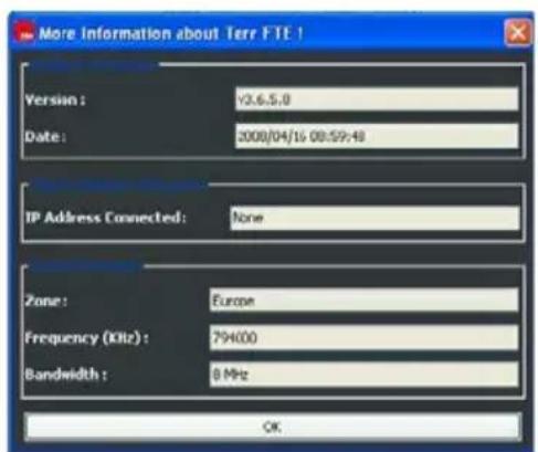
We can obtain more information about a given device selecting it with the mouse and using the right button to execute 'More Info' or clicking the icon ⚙. The additional information is in relation with the firmware version embedded on device, with the tuned transponder, reception quality, BER, power, and/or with CI slots status (in case of CI hardware option).
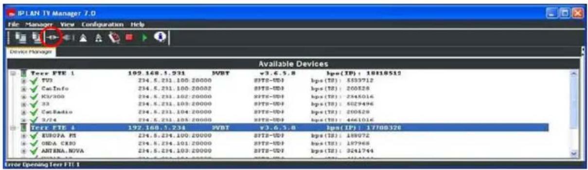
2.3. Management Tasks
The management commands are applied to the selected device (highlighted line), but not the "Set MPTS/SPTS Mode", "Device Settings" and "LNB Settings" commands that are applied to the device "connected" (symbol "C"). In the following figure you can see that the selected device, and the device connected can be different ones. A selected device is done by a simple click on the desired device, and a device connected can be by three different ways: doing a double click on the device, or selecting the device (simple click) and either clicking the 'Connect' icon (===) or doing the menu option "Manager/Connect".
2.3.1. Configuration of the device parameters
We can configure the device parameters by clicking the menu option "Configuration/Device Settings" or clicking the icon
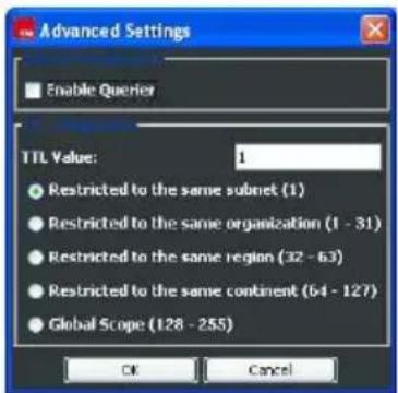
. These parameters are: name, network settings (IP address, net mask and gateway address), "querying" status and TTL value. These two last parameters are inside "Advanced Options".
The "querying" status parameter is in relation with the multicasting management. Normally, the multicast traffic generated by these devices is distributed through routers and switches that must support IGMPv2. In these distribution networks there must be a "querier" that generates 'IGMP query' messages. This function is generally made by a router/switch, but if it is not present you can configure an only one device to perform this function. The port of the switch or router where this "querying" device is attached to, must support all the multicasting traffic existing in this switch/router. The "querying" status of the device can be displayed and modified in "Enable Querier" tick.
The TTL parameter value refers to the value of "Time To Live" field, in the streaming traffic generated from the device. When an IP packet comes in a router/switch, if its TTL is non zero, the packet will be propagated with the TTL decremented by 1. So, this value gives us an idea of the scope for the streaming traffic generated by these devices. The "querying" status and TTL value is configured through the following window.
2.3.2. Configuration of the LNB parameters (DVB-S / DVB-S2)
This configuration only applies to DVB-S / DVB-S2 devices and is in relation with the power supply features that the device provides to the antenna LNB. These features determine the transponders that the device can tune: they establish the possible band and polarization for the tuned transponders.
These parameters with their default values are presented in the following figure.
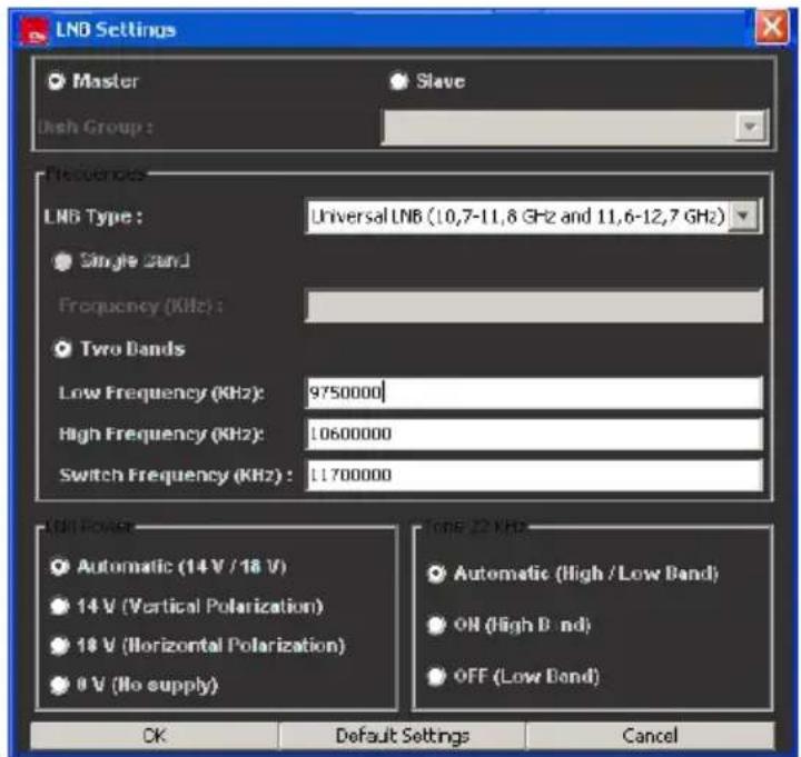
Firstly, the device can be configured as MASTER supplying LNB (DVB-S/S2 M), or as SLAVE not supplying LNB (DVB-S/S2 S). The antenna LNB has to be supplied, so if there are some devices plugged to the same LNB, only one has to be configured as MASTER and supply the LNB. The rest of the boards has to be configured as SLAVE associated with the MASTER (we select the MASTER IP address in the "Dish Group" box).
In case of MASTER device, we have to select the LNB type that we are using. For an universal LNB, we present the following parameters and their default values:
- LNB Low Frequency (MHz) = 9,750 (local oscillator for lower band)
- LNB High Frequency (MHz) = 10,600 (local oscillator for higher band)
- LNB Switch Frequency (MHz) = 11,700
If we are using a different LNB type, the important data to know about it is the number of the local oscillators (single or double band), and the value of its local oscillators.
The tuner of the device presents a frequency range 0.95-2.15 GHz and using an universal LNB, the Ku band (10.7 - 12.75 GHz) is completely covered:
- Low Band: 10.70 - 11.9 GHz (9.75+0.95) - (9.75+2.15)
- High Band: 11.55 - 12.75 GHz (10.6+0.95) - (10.6+2.15)
The parameter "LNB Switch Frequency" fixes the limit between using the lower or higher local oscillator of the LNB. Finally, when the device is MASTER, we can force the characteristics of the power supply to LNB (level and tone). We recommend you to keep these parameters in automatic: the level and tone values are set according the polarization and sub-band of the transponder you are tuning at every moment.
2.3.3. Firmware Update
The IP LAN TV Manager presents the option to update the firmware embedded in the selected device or in all devices existing in the local segment, by clicking the menu options "Manager/Upload" and "Manager/Upload ALL" (△ and ▲ respectively in the icon bar). In both cases, a dialog window comes up, inviting you to introduce the binary file to upload. Once the firmware update is finished, the device will be restarted.
2.3.4. Initialization
The menu option "Manager/Reset" allows initializing the selected device, leaving intact the current configuration including the streaming services previously configured.
2.3.5. Suspend and Resume
The menu options "Manager/Suspend", "Manager/Resume", "Manager/Suspend ALL", and "Manager/Resume ALL", allow suspending or resuming the selected device or all existing devices in the local network (■ and ▶ respectively in the icon bar).
The device suspension implies that the device stops the streaming of all its running services. As a consequence of suspension, the traffic light of the device will change to red and the green ticks of the running services to yellow. In the same way, in "Streaming Services" tab, the green color of the running services will change to yellow.
When we resume the device, the previously suspended services will return to be streamed out. These services will return to green.
A device initialization caused by either a hardware reset or a command from the application (Upload and Reset), implies a resume of the all suspended services.
2.3.6. Management of the slots "Common Interface" (-CI)
When a device with the option hardware CI is connected, there is a new menu in the application: "CI Manager". By means of this new menu, we will be able to obtain information about conditional access modules (CAM) inserted in the slots, and carry out operations on them, as reset and power off. Also, we will be able to enter the proprietary menus of the CAM inserted.
2.3.7. Events Logging
There are two buttons (arrows) in the right border of the main window in order to maximize or minimize the logging window. This window contains a registration of all the events related to any change of the status in the devices or its associated services. Besides, it includes a registration of the commands executed from menu option "Manager".
2.4. Configuration
Firstly, we have to check that device is operating on the desired mode (see paragraph 2.1). In order to change the operation mode, we should execute the corresponding menu option "Configuration/Set xxx Mode". When we change the operation mode, the previous service configuration is deleted.
Once the operation mode is selected, the configuration of a DVB-IP device will consist in the following steps:
- Search for the available services/transponders that the device receives.
- Definition of the streaming services.
- Start and stop the streaming services.
In order to configure a device, firstly we must connect to it. We remind you that a board connected is set up by three different ways: doing a double click on the device, or selecting the device (simple click) and either clicking the 'Connect' icon or doing the menu option "Manager/Connect".
We can configure a device which is not listed (the application couldn't detect it), if we know that it is available (check by a ping to the IP address using a command console) and we know its IP address. We have to click in the menu option "Manager/Manual connection". If the application achieves to connect the device, this will be added to the list with an unknown state (?).
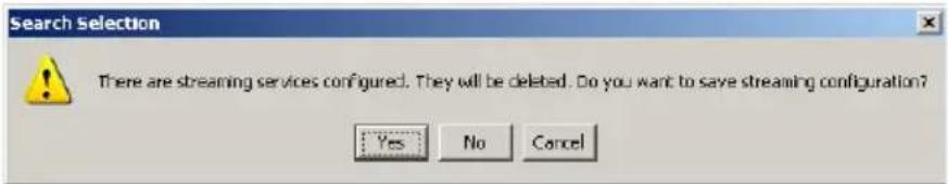
Whatever operation that implies a deletion of the configured services in the device, as is a change in the operation mode or in the tuning/demodulating parameters, the application warns and invites us to save the previous configuration in a file for its subsequent recovery.
Before analyzing the search and configuration of services, we are going to see a summary of the different options in the streaming mode. We analyze further the cautions to follow in order to configure DVB-S / DVB-S2 devices in case they are sharing LNB. Finally, we will see the features in the configuration of devices that include the hardware option "Common Interface".
2.4.1. Streaming Mode
The streaming mode of a service refers to the content and encapsulation protocol over what is sent via ethernet related to the service, and it is depending on the device operation mode:
In SPTS mode, there are two possibilities:
- Transport Stream: The transport stream related to the configured PIDs for the service is encapsulated in IP using UDP or RTP protocols and unicast or multicast addressing. In this case, the device generates and sends the service information tables (PAT, PMT y SDT).
- MultiProtocol IP (MPE): The device sends via ethernet the IP packets included in special sections MPEG (encapsulated in TS) that are transmitted in DVB. Using this streaming mode, the device can filter the IP packets corresponding to the configured multicast IP address, inside the MPEG section related to the configured PID (only a PID per service). If "Uses IP to MAC mapping" tick is marked, the device will filter all IP packets corresponding to the first 'x' bytes (less meaning) of the MAC address (using multicast to MAC mapping), associated to the configured PID. If this tick is not marked, the device will extract all IP packets corresponding to the configured PID.
In MPTS mode, the filtered information can be encapsulated in IP using UDP or RTP protocols and unicast or multicast addressing. In this case, the device doesn't generate any service information table.
2.4.2. Search for the available services/frequencies
This step is not necessary if the services or transponders to configure are already in the "Database" in the SPTS or MPTS mode respectively, or they are previously saved into a configuration file. If they are not, we have to make a previous search. Independently the operation mode, we always refer to a services search, although depending on the operation mode, the "Database" tab will show the list of available services (SPTS mode), or a list of available transponders (MPTS mode).
The search in DVB-S, DVB-S2, DVB-T and DVB-C devices can be done in two different ways: manual (1) or automatic (2). For DVB-T devices, the available transponders depend on the zone where we are; for DVB-C devices the available services depend on the cable operator, and for DVB-S devices depend on the satellite where the antenna is oriented. The data of all available transponders for every satellite are updated in the web page www.lyngsat.com. We are interested in the satellites that broadcast DVB services. Obviously, we can only tune the transponders associated to the satellite that our antenna is pointing to.
Whatever search in a transcoder or frequency different to the currently tuned, will cause a deletion of the configured services, in case they were. The application will warn and invite us to save this configuration before being deleted.
2.4.2.1. Manual search in DVB-S, DVB-S2, DVB-T and DVB-C devices
The manual search allows the search of services included in a given transponder or channel. In order to search we have to execute the menu option "Search/Manual Search", having selected the "Database" tab. It comes up one of the following windows depending on the device type is being used:
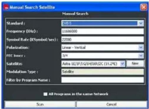
DVB-S / DVB-S2
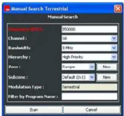
DVB-T
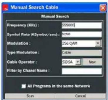
DVB-C
Through these windows, we introduce the parameters related to the tune/demodulating of the desired transponder:
- DVB-S / DVB-S2: frequency, symbol rate, polarization and FEC.
- DVB-T: frequency or channel, bandwidth, hierarchy and zone.
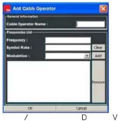
- DVB-C: frequency, symbol rate and constellation.
The rest of parameters, satellite for DVB-S / DVB-S2, subzone for DVB-T and cable operator for DVB-C, are simply used to classify and store properly the search results (services/frequencies). We can add, modify or delete these elements using the corresponding "Services" menu option.
Once the search parameters are introduced and we click the "Scan" button, the application starts to search for the available services in the selected frequency.
If we want to search for a given service, we also have to introduce its name in the "Filter by Channel Name" box.
If we tick "All programs in the same Network" for transponder case, the application will search for in all transponders associated to the same network. This action is equivalent to do an automatic search in a given network. During the services search, the application shows up the process state by the following window:
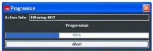
If we click on "Abort" button, the search is cancelled and the services/frequencies found at this moment, are shown up. Once the search is finished, the resulting services/frequencies are highlighted in the "Database".
2.4.2.2. Automatic search in DVB-S, DVB-S2, DVB-T and DVB-C devices
The automatic search allows the search of all services included in the input signal. In order to search we have to execute the menu option "Search/Automatic Search", having selected the "Database" tab. As in the manual search, to execute the command implies the deletion of a previous services configuration in the device, and the application will warn you. Depending on the device type:
a) Automatic search in DVB-S, DVB-S2 and DVB-C devices
The application shows the following window that invites you to introduce the satellite or the cable operator in which the search results are going to be saved.
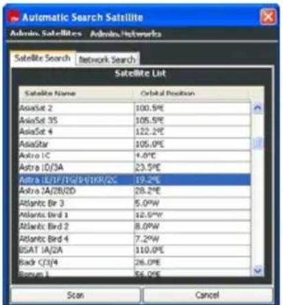
DVB-S / DVB-S2
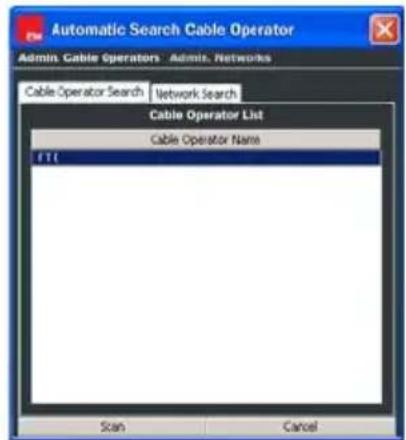
DVB-C
Selecting a satellite/cable operator and clicking the "Scan" button, the application will start the search for every service included in all frequencies related to the satellite/operator, and in all frequencies included in the network information (NIT) of the previous ones. The results are presented in the same way as in the manual search case.
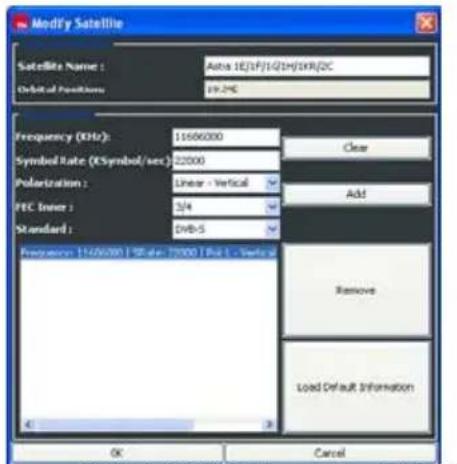
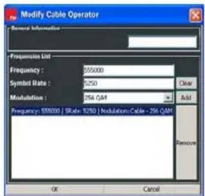
In order to see the frequencies related to a satellite/operator, we make a double click on the satellite/operator, or either "Admin. Satellites/Modify Satellite" or "Admin. Cable Operators/Modify Cable Operator" menu options are executed.
DVB-S / DVB-S2
DVB-C
This list includes all previously scanned frequencies for the satellite/operator. In case of DVB-S, if there wasn't any previous search for a satellite, the frequencies list is empty, but we can load a default frequency list by clicking "Load Default Information" button. As many transponders we have in the list, the automatic search result will be more. In this window we can edit new or existing transponders, and add or delete it in the list associated to the satellite.
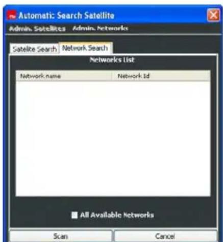
In the tab "Network Search" of "Automatic Search", we find a list of all networks for the selected satellite/operator, which were previously found.
DVB-S / DVB-S2
Selecting a network, and clicking "Scan", the application starts the search for every services belonging to this network. If we tick the option "All Available Networks", the search will be done for all available networks for the satellite/operator.
This action is equivalent to do an automatic search for the satellite/operator.
If you want to search for a satellite/operator that is not in the list, you can add it executing the menu option "Admin. xxx/Add xxx". In the following window you introduce the name and the set of frequencies for an initial automatic search.
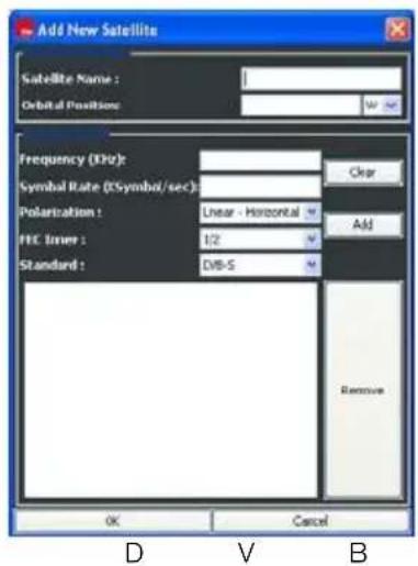
In order to modify the data of a existing satellite/operator, you can select this one from the list, and click on the menu option "Admin. xxx/Modify xxx". If you want to delete all data about a satellite/operator, you have to select this one and click on "Admin. xxx/Delete xxx".
Unlike the satellites/operators list, the only modification permitted on the network list, is the deletion. Therefore, if we want to delete the data of a network associated to a satellite/operator, we have to select the network and click on the menu option "Admin. Networks/Delete Network".
b) Automatic search in DVB-T devices
The application shows a window to introduce the world region where we are, the subzone where the results will be saved, the channel bandwidth and the hierarchy that are used for the target services. In the most of the countries the channel bandwidth is 8 MHz, but in other countries can be different (6 or 7 MHz).
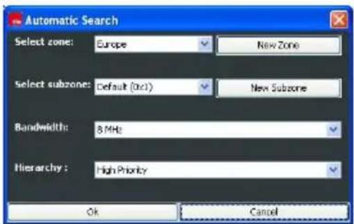
After clicking OK, the application will search for in all available channels in the selected region. In this case, all services that are found, are grouped under a network that is named as the selected subzone. The results are presented in the same way as other searches.
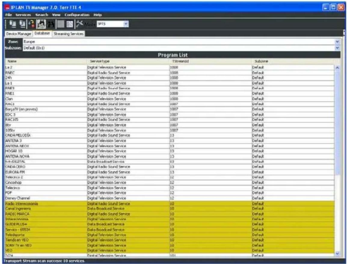
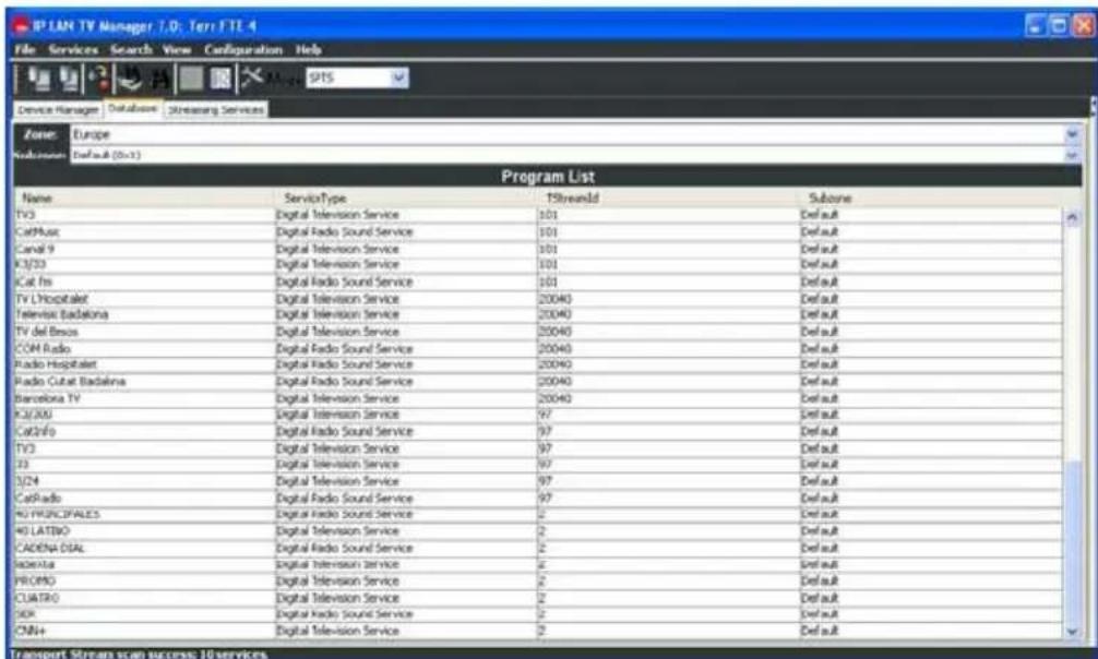
2.4.2.3. Service/Frequency list
After any kind of search in any device, all services that have been found will be stored in a database of services and frequencies. There will be four different databases corresponding to each device type. The services (SPTS mode) and transponders (MPTS mode) in the database are displayed on "Database" tab.
In the case of DVB-T devices, the available services/frequencies are grouped in world zones; meanwhile, in the case of DVB-S/S2 and DVB-C devices, the available services/ frequencies are grouped in satellites or cable operators and networks.
In order to see the services/ frequencies related to a given zone/satellite/operator/IP and subzone/network, you have to select these parameters from the drop-down lists placed at the top of the window.
DVB-S / DVB-S2
The following data are displayed for each service:
- Name: Name of the service
- Service Type: Type of the service. It can be:
• Digital Television Service.
• Digital Radio Sound Service.
• Data Broadcast Service.
• MPEG2 HD Digital Television Service.
- Unknown Service Type.
- TstreamId: Transponder identifier associated to the service.
- NetworkName: Name of the network related to the service.
Apart from this data, we can get more information from the selected service through the menu option "View/Advance View" (☐). To click on this option, a new frame appears on the right side of the window, with information about the service: network, frequency, assigned PIDs, conditional access, and other information as name, language, etc... This advance view is kept in the "Streaming Services" tab on the service selected.
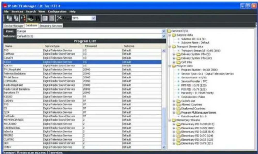
DVB-S / DVB-S2
In order to manage easier the services list, the application allows applying a filter to one of the previously mentioned four fields. In this way, we can display a subset of services that complies the filter. To define this filter, click on the menu option "View/Filter". Once this is done, the following window comes up:
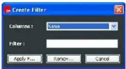
In this window, we can select the field to filter and the desired value. To apply the filter, we click on "Apply Filter" button. If we want to remove the filter, we click on the menu option "View/Filter", and click on "Remove Filter" button. The service/frequency list stored in the database is enlarged with the results from consecutive searches. We can delete services from the database in three different ways from the menu "Services":
- Select a satellite or cable operator name (only for DVB-S, DVB-S2 and DVB-C) from the drop-down list and click on the menu option "Delete xxx". This option will erase all services/frequencies about the selected satellite/operator.
- Select a network name from the drop-down list and click on the menu option "Delete Network". This option will erase all services/frequencies about the selected network.
- Select one or some services from the list and click on the menu option "Delete Service/s". This option will erase only the selected services.
All data about the services/transponders that have been found are saved in the file "SystemData.xml" located in the application root path. We can export these data to another file 'xml' with the menu option "File/Export Database" (☐). Also, the application presents the option to work with other services lists, importing these data from a file with extension 'xml' (it is supposed to be exported previously). In order to do this, you click on the menu option "File/Import Database" and select the file that contains the data (☐).
2.4.3. Definition of the streaming services
In SPTS mode, there are three different ways to define a new streaming service:
- From a service in the database.
- From a streaming service just defined.
- From information in database with no previous service reference.
- Meanwhile, in MPTS mode only is possible to define the streaming service from a transponder existing in database.
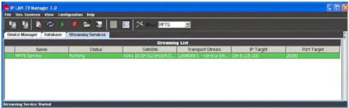
The streaming services defined for a given device are listed in "Streaming Services" tab. The list showed in this tab is associated to the device to configure.
Independently the operation mode, the streaming services configuration can be restored from a file that has been previously saved. The menu options "Stm. Services/Load Streaming Configuration" and "Stm. Services/Save Streaming Configuration" are used to do this.
An example of streaming services list is the following:
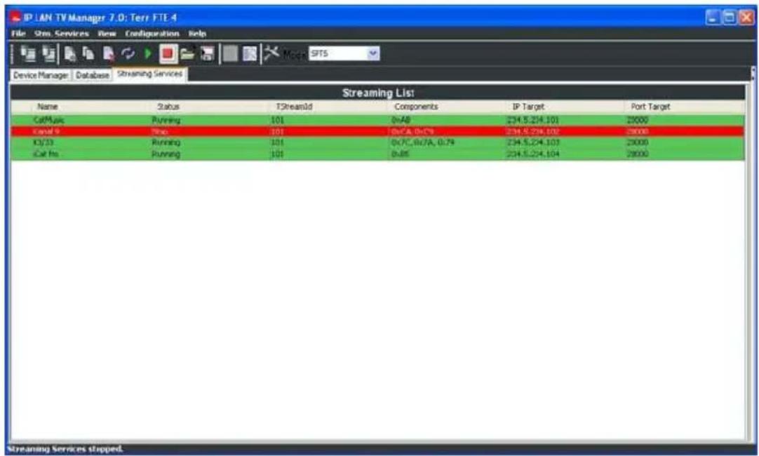
The following data are presented for each streaming SPTS service:
- Name: Name of the streaming service.
-
Status: Status of the streaming service. The possible values are:
-
No Config: the streaming service has just been added to the list and it has not been defined yet in the device.
- Running: the streaming service has been defined as "running"; if it is on green, the device is streaming it out, but if it is on yellow the service is either suspended or the device is not receiving signal from.
-
Stop: the streaming service has been defined as "stopped"; the device is not streaming it out.
-
TstreamId: Identifier of the transponder which the service belongs to.
- Components: Enumeration of the PIDs that makes up the streaming service.
- IPTarget: Multicast/unicast address related to the streaming service. If this value is not introduced before starting the service, the application set automatically a default value for it. Afterwards, you can modify this parameter if you wish.
- PortTarget: Target port related to the streaming service.
Meanwhile, the information presented for a MPTS service is the same except Components and TstreamId, being substituted by the frequency information.
The parameters associated to a streaming service can be modified, whenever this service is not running, making a double click on it, or executing the "Stm Services/Modify Streaming Service" menu option.
2.4.3.1. Definition of a streaming service from an existing service/transponder in database
This way to define a streaming service is the more common. From "Database" tab, we select the service or services that we want to define as streaming services. These services pass to the "Streaming Services" clicking on the icon, or on the menu option "Services/Create Streaming Service(s)". In MPTS mode we can only add a service, but in SPTS mode it is possible to add up to eight services in the same transponder.
In SPTS mode, by default, the application adds up the services only with video and audio PIDs (plus PCR PID); but if the user wants to create the services with all the PIDs that make up them, from "Database" tab, he has to select the menu option "View/Advanced View", and with the service(s) selected, pulse the menu option "Services/Create Streaming Service(s) with ALL PIDs". You have to be careful with this alternative because you can add up PIDs that are not necessary for our goal, and run out the device hardware resources; so, if you want to add up any PID different from video or audio, we recommend you add up these PIDs modifying the service created with only video and audio PIDs (menu option "Stm Services/Modify Streaming Service").
In order to add up the information of some descriptors included in the original PMT associated to the service, we should activate "Enable PMT Descriptors" tick and select those we want to introduce. When a descriptor is added, the possible component or components associated are also added; this is the case of the teletext descriptor: if we add the teletext descriptor (tag 0x56), the component or PID that contains the teletext data is added up.
A streaming service defined like this, initially presents a "No Config" state and all video and audio PIDs that make up the original service. The generated IP Target belongs to the multicast address range and follow the rule configured and explained in the paragraph 8.2. The default value for Port Target is 20000. The default Streaming Mode is SPTS-UDP o MPTS-UDP depending on the operation mode.
2.4.3.2. Definition of a streaming service from an existing streaming service (SPTS)
In order to define a streaming service from an existing one, we have to select this one and copy it, clicking on the menu option "Stm Services/Copy Streaming Service".
Once it is copied, the new service will be in the list as a copy of the former but with the PIDs field unassigned. Before the new service can be started, it is necessary to edit the PIDs field. The definition of the rest of the parameters for the new service will follow the rules seen in previous paragraph.
2.4.3.3. Definition of a streaming service with no previous service reference (SPTS)
In order to define a new service, we have to click on the menu option "Stm Services/Add New Streaming Service" (L). The following window will pops up with different tabs "General Information", "PIDs Information" and "Descriptors Information":
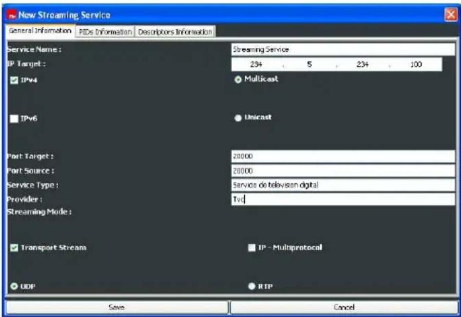
"General Information": this tab includes the basic parameters of the streaming service, as name, IP addressing and streaming mode:
- "Service Name": mandatory field that means the name of the streaming service.
- "IP Target": mandatory field that indicates the target IP address. This address can be configured as multicast or unicast. In case of multicast address, this will be in the range 224.0.0.0 - 239.255.255.255. We recommend see the documents RFC 3171 and 2365 for a proper multicast address choice. In this case, the traffic generated from the device for this service is multicast and would be received by all clients joined to this multicast group. See IGMP protocol.
In case of unicast address, the traffic generated from device will reach only the given address.
- "IP version": at this moment, the device only supports version 4. In a future, it will also support version 6.
- "Port Target": mandatory field that means the target port related to the streaming service. This value can be in the range 1026 - 65535 and has to be multiple of 2.
- "Port Source": mandatory field that means the source port related to the streaming service. This value can be in the range 1026 - 65535 and has to be multiple of 2.
- "Service Type": optional field where we can introduce a short description of the streaming service.
- "Provider": optional field where we can introduce the provider name of the streaming service.
- "Streaming Mode": mandatory field that indicates the content type and protocol used in the service streaming: SPTS-UDP, SPTS-RTP and IP-Multiprotocol (MPE) for devices in SPTS mode, and MPTS-UDP, MPTS-RTP for devices in MPTS mode.
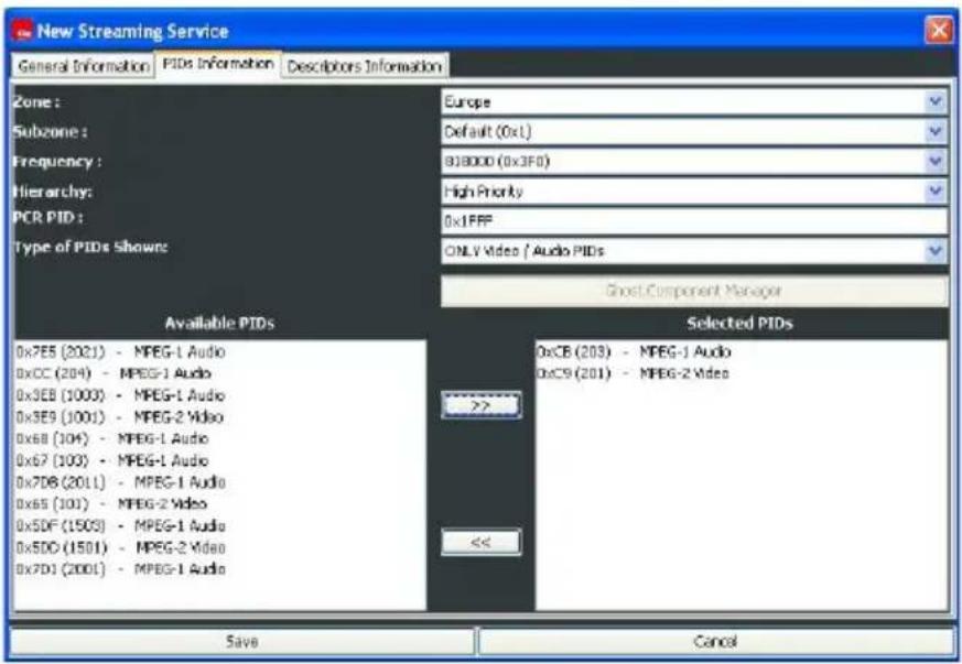
The information in "PIDs Information" and "Descriptors Information" are only applied for devices in SPTS mode:
"PIDs Information": mandatory field that enumerates the list of PIDs to be filtered and streamed out. We can only use the PIDs previously found to fill in this field. For DVB-S, DVB-T and DVB-C devices, these PIDs are associated to frequencies, these are associated to networks and finally these are to satellites for DVB-S, subzones and zones for DVB-T and cable operators for DVB-C. We notice that the list of PIDs only can be made up by PIDs belonging to an unique frequency, and it is not possible more than a video PID. The list of available PIDs can show either VIDEO/AUDIO PIDs or all PIDs that are found in the PMT of all services in the selected transponder. In case that all PIDs are shown, using the "Ghost Component Manager" button, we can add PIDs not present in the PMTs in order to select them.
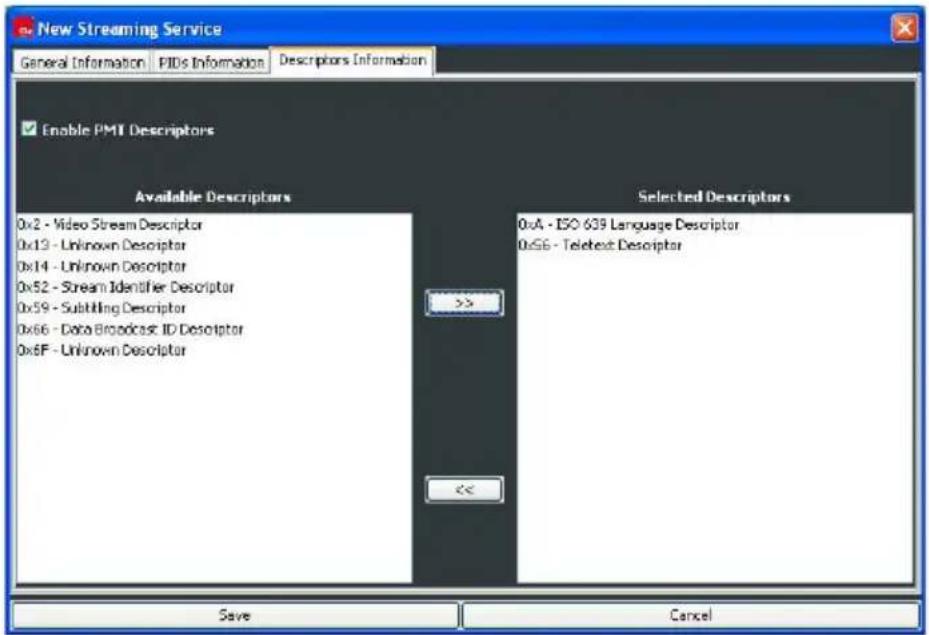
"Descriptors Information": When we create a service, the device generates the following service information tables: PAT, PMT and SDT which refers to the new service created and its components. By default, the PMT doesn't contain any descriptor, and if we want to introduce any type of it, we must tick "Enable PMT Descriptors", and select whatever type we want. Be careful, because the PMT present a length limit, so we can not introduce all we want. If the descriptor has information associated in other components, these components will be automatically added up, when the descriptor is selected. The addition of some descriptors in PMT generation is completely necessary, so any player can recognize some information added to the TS, as teletext or AC3 audio information.
Once we have filled out the data, it is necessary to click on "Save" button to add the service to the "Streaming Services" list.
In the same way we have defined all these parameters for a new streaming service, we can edit or modify it, with the only condition that the service has not be running. To proceed with the service edition, we have to select it and click double on the field to edit, or click on the menu option "Stm Services/Modify Streaming Service".
Finally, we have to notice that we can delete streaming services from the list, selecting it and clicking on either the menu option "Stm Services/Delete Streaming Service/s", or the icon 📄.
2.4.4. Start and stop a streaming service
In order to start a streaming service is necessary to select it and click on either the icon or the menu option "Stm Services/Start Streaming Service". If the communication between application and device has been successful and the streaming service has been started, its status will change to "Running" in green color.
In order to stop a streaming service is necessary to select it and click on either the icon or the menu option "Stm Services/Stop Streaming Service". If the streaming service has been stopped, its status will change to "Stop" in red color.
2.4.5. Configuration of DVB-S/DVB-S2 devices sharing the same antenna
This subject only applies to DVB-S / DVB-S2 devices that are sharing the same LNB, that is, the same cable from the antenna: LNB has to be supplied only by a device. The device that supplies LNB is configured as MASTER, whereas the rest of the devices are configured as SLAVE. In the boards list (Device Manager tab), firstly is the MASTER device followed by the SLAVE devices associated. If there is a SLAVE device associated to a MASTER device not present in the list, this will appear with the status SLAVE??? in red color.
We RECOMMEND to configure the group of devices MASTER – SLAVEs, being connected simultaneously to the network, and configure firstly the MASTER device, and afterwards the SLAVE ones.
The configuration of the MASTER is made normally following the steps previously explained. Once the MASTER device is configured, we proceed with the rest of the devices configured as SLAVE, taking into account that it is only possible to do automatic/manual searches or configure services in transponders at the same band and with the same polarization that the transponder tuned in the MASTER device.
For a better explanation, we are going to analyze a practical example, putting special emphasis on one of the configuration parameters of the LNB (LNB Switch): We have three devices with no previous configuration and sharing an universal LNB of an antenna pointing to ASTRA satellite. We want to configure the devices with streaming services in the following transponders:
- Freq: 11.568 MHz Pol: V (RAI Uno, ARTE)
- Freq: 11.597 MHz Pol: V (BBC, CNBC)
- Freq: 11.686 MHz Pol: V (TVC, TV Galicia)
In an universal LNB, we present the following parameters and their default values:
- LNB Low Frequency (MHz) = 9,750 (local oscillator for lower band)
- LNB High Frequency (MHz) = 10,600 (local oscillator for higher band)
- LNB Switch Frequency (MHz) = 11,600
The tuner of the device presents a frequency range 0.95-2.15 GHz and using an universal LNB, the Ku band (10.7 - 12.75 GHz) is completely covered:
- Lower band: 10.70 to 11.9 GHz (9.75+0.95) to (9.75+2.15)
- Higher band: 11.55 to 12.75 GHz (10.6+0.95) to (10.6+2.15)
The parameter "LNB Switch Frequency" fixes the limit between using the lower or higher local oscillator of the LNB.
As we have said before, the transponders tuned by different devices that share the same LNB, must be at the same band and present the same polarization. The three transponders present the same polarization, but according to the LNB parameters, the first two are at the LOW band and the third at the HIGH one. In order to get along the three transponders, we can take advantage of the certain flexibility that LNB Switch parameter presents: it can be slightly modified to 11.700 MHz in a board, so the three transponders are now at the same band (LOW). The configuration would be:
- IPS 310 1: RAI Uno, ARTE. MASTER
- IPS 310 2: BBC, CNBC. SLAVE
- IPS 310 3: TVC, TV Galicia. SLAVE y LNB Switch 11.700 MHz
The flexibility for the "LNB Switch" parameter depends on the value of the LNB local oscillators. For an universal LNB, the LNB Switch Frequency will be in the range 11.55 - 11.9 GHz.
2.4.6. Configuration of services in devices with "Common Interface" option
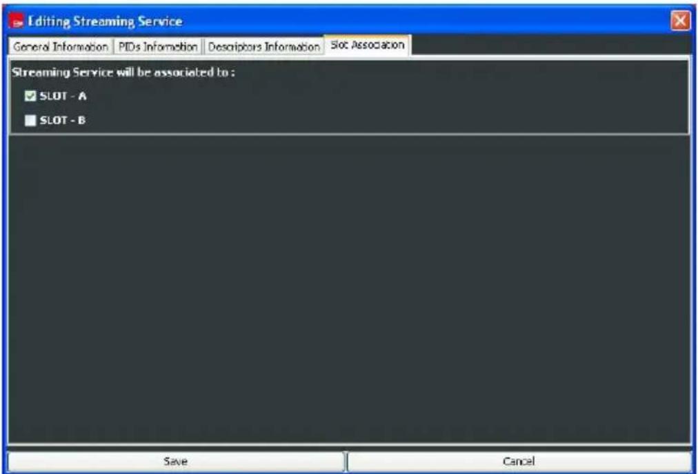
The configuration of streaming services in a device that includes the hardware option CI is exactly in the same way that in a device with no CI option, but in case we want to descramble services using conditional access modules (CAM), it will be necessary to do an additional configuration step: "Slot Association".
In order to descramble a service using one or two conditional access modules, besides inserting the modules into available CIs, we have to associate the service with the corresponding slot/s. In this way, if a service presents a "Scrambled" status, and is associated to at least one slot, where a suitable CAM and smartcard are inserted, the service is descrambled and ready to be streamed out.
NOTE: Every time you modify the configuration of services associated to slots, it is recommended to RESET the board to assure a correct performance.
- Technical features
| Reference | IPS 310 IPS 310 CI | ||
| Code | 2003510 | 2003514 | |
| Description | DVB-S / DVB-S2 --> IPTV DVB-S (CI) | / DVB-S2 (CI) --> IPTV | |
| Input | RF connectors Female F connector Female F connector | ||
| Input frequency range (MHz) 950-2150 950-2150 | |||
| Input level (dBm) -25 to -65 -25 to -65 | |||
| Input impedance () 75 | 75 | ||
| Symbol speed (MS/s) | DVB-S:1-45 DVB-S2:1-36(QPSK)/1-30(8PSK) | DVB-S:1-45 DVB-S2:1-36(QPSK)/1-30(8PSK) | |
| Modulation | QPSK / 8PSK | QPSK / 8PSK | |
| FEC | DVB-S:1/2, 2/3, 3/4, 5/6, 6/7, 7/8DVB-S2:1/2, 3/5, 2/3, 3/4, 4/5, 5/6, 8/9, 9/10 | DVB-S:1/2,2/3,3/4,5/6,6/7,7/8DVB-S2:1/2,3/5,2/3,3/4,4/5,5/6,8/9,9/10 | |
| Losses in LOOP (dB) | <1 | <1 | |
| Services / programs filters | Up to 8 | Up to 8 | |
| LNB (Feeding/communication) | 13V/18V, 0-22kHz | 13V/18V, 0-22kHz | |
| Output | Connector | RJ-45 | RJ-45 |
| Interface protocol | Ethernet 802,3 | Ethernet 802,3 | |
| Output speed | 10/100Mbps | 10/100Mbps | |
| Service information protocol | SAP / SDP | SAP / SDP | |
| IGMP protocol | v1,v2 | v1,v2 | |
| IP extraction and encapsulation | IP over MPEG 2 Transport Stream (ETSI EN 301 192) | IP over MPEG 2 Transport Stream (ETSI EN 301 192) | |
| Table rule out or pass | NIT,SDT,EIT and TDT | NIT,SDT,EIT and TDT | |
| Table regeneration | PAT, PMT and CAT | PAT, PMT and CAT | |
| Others | Condicional access | No | Yes, 2 slots |
| Running temperature 0° from 45° | 0° from 45° | ||
| Measures (mm) | 75 x 265 x 150 | 75 x 265 x 150 | |
| Weight (Kg) | 1,2 | 1,3 | |
| Consumption 5V (mA) | DVB-S: <800 mADVB-S2: <1500 mA | DVB-S: <1050 mA + PCMCIA'sDVB-S2: <1750 mA + PCMCIA's | |
| Consumption 12V (mA) | --- | --- | |
| Consumption 24V (mA) | <250mA | <250mA | |
| Consumption 30V (mA) | --- | --- | |
| Quantity per package | 1 | 1 | |
| Reference IPT 310 IPT 310 CI | |||
| Code 2003508 | 2003512 | ||
| Description | DVB-T --> IPTV DVB-T (CI) --> IPTV | ||
| Input | RF connectors Female F connector Female F connector | ||
| Input frequency range (MHz) | VHF: 174 - 230UHF: 470 - 862 | VHF: 174 - 230UHF: 470 - 862 | |
| Input level (dBm) -20 to -65 -20 to -65 | |||
| bandwidth (MHz) DVB-T (7-8) DVB-T (7-8) | |||
| Input impedance () 75 | 75 | ||
| FEC | 1/2, 2/3,3/4,5/6,7/8 | 1/2, 2/3,3/4,5/6,7/8 | |
| Losses in LOOP (dB) | <1 | <1 | |
| Modulation | COFDM | COFDM | |
| Services / programs filters | Up to 8 | Up to 8 | |
| Reception mode | DVB-T (2K,8K) | DVB-T (2K,8K) | |
| Output | Connector | RJ-45 | RJ-45 |
| Interface protocol | Ethernet 802,3 | Ethernet 802,3 | |
| Output speed 10/100Mbps | 10/100Mbps | ||
| Service information protocol | SAP / SDP | SAP / SDP | |
| IGMP Protocol | v1,v2 | v1,v2 | |
| IP extraction and encapsulation | IP over MPEG 2 Transport Stream (ETSI IN 301 192) | IP over MPEG 2 Transport Stream (ETSI IN 301 192) | |
| Table rule out or pass | NIT,SDT,EIT and TDT | NIT,SDT,EIT and TDT | |
| Table regeneration | PAT, PMT and CAT | PAT, PMT and CAT | |
| Others | Condicional access | No | Yes. 2 slots |
| Running temperature 0° to 45° | 0° to 45° | ||
| Measures (mm) | 75 x 265 x 150 | 75 x 265 x 150 | |
| Weight (Kg) | 1,2 | 1,3 | |
| Consumption 5V (mA) | <1000mA | <1250 mA + PCMCIA's | |
| Consumption 12V (mA) | --- | --- | |
| Consumption 24V (mA) | --- | --- | |
| Consumption 30V (mA) | --- | --- | |
| Quantity per package | 1 | 1 | |
| Reference IPQ 310 IPQ 310 CI | |||
| Code 2003528 | 2003530 | ||
| Description | DVB-C --> IPTV DVB-C (CI) --> IPTV | ||
| Entrada | RF connectors Conector F hembra Conector F hembra | ||
| Input frequency range (MHz) 50 - 858 50 - 858 | |||
| Input level (dBμV) | 42 to 82 42 to 82 | ||
| bandwidth (MHz) 8 | 8 | ||
| Symbol speed (MS/s) 1,9 - 6,9 | 1,9 - 6,9 | ||
| Services/programs filter | Up to 8 | Up to 8 | |
| Losses in LOOP (dB) | <1 | <1 | |
| Input impedance ( ) | 75 | 75 | |
| Modulation | OAM | OAM | |
| Output | Connector | RJ-45 | RJ-45 |
| Interface protocol | Ethernet 802,3 | Ethernet 802,3 | |
| Output speed | 10/100Mbps | 10/100Mbps | |
| Service information protocol | SAP / SDP | SAP / SDP | |
| IGMP Protocol | v1,v2 | v1,v2 | |
| IP extraction and encapsulation | IP over MPEG 2 Transport Stream (ETSI IN 301 192) | IP over MPEG 2 Transport Stream (ETSI IN 301 192) | |
| Table rule out or pass | NIT,SDT,EIT and TDT | NIT,SDT,EIT and TDT | |
| Table regeneration | PAT, PMT and CAT | PAT, PMT and CAT | |
| Others | Condicional access | No | Yes, 2 slots |
| Running temperature | 0° to 45° 0° to 45° | ||
| Measures (mm) | 75 x 265 x 150 | 75 x 265 x 150 | |
| Weight (Kg) | 1,2 | 1,3 | |
| Consumption 5V (mA) | <1000mA | <1250 mA + PCMCIA's | |
| Consumption 12V (mA) | --- | --- | |
| Consumption 24V (mA) | --- | --- | |
| Consumption 30V (mA) | --- | --- | |
| Quantity per package | 1 | 1 | |
4. Declaration of conformity

CONFORMITY DECLARATION
"WE, FTE MAXIMAL, DECLARE THAT THE PRODUCTS IPT 310, IPT 310 CI, IPS 310, IPS 310 CI, IPQ 310, IPQ 310 CI ARE IN CONFORMITY WITH FOLLOWING DIRECTIVES Low Voltage Directive 2006/95/EC EMC Directive 2004/108/EC"
If you wish a copy of the conformity declaration, please contact to the company