OnCell 5004-HSDPA-JPS - Communication Module Moxa - Free user manual and instructions
Find the device manual for free OnCell 5004-HSDPA-JPS Moxa in PDF.

User questions about OnCell 5004-HSDPA-JPS Moxa
0 question about this device. Answer the ones you know or ask your own.
Ask a new question about this device
Download the instructions for your Communication Module in PDF format for free! Find your manual OnCell 5004-HSDPA-JPS - Moxa and take your electronic device back in hand. On this page are published all the documents necessary for the use of your device. OnCell 5004-HSDPA-JPS by Moxa.
USER MANUAL OnCell 5004-HSDPA-JPS Moxa
OnCell 5000 Series User's Manual
Third Edition, August 2010
www.moxa.com/product
MOXA®
© 2010 Moxa Inc. All rights reserved. Reproduction without permission is prohibited.
OnCell 5000 Series User's Manual
The software described in this manual is furnished under a license agreement and may be used only in accordance with the terms of that agreement.
Copyright Notice
Copyright ©2010 Moxa Inc.
All rights reserved.
Reproduction without permission is prohibited.
Trademarks
The MOXA logo is a registered trademark of Moxa Inc.
All other trademarks or registered marks in this manual belong to their respective manufacturers.
Disclaimer
Information in this document is subject to change without notice and does not represent a commitment on the part of Moxa.
Moxa provides this document as is, without warranty of any kind, either expressed or implied, including, but not limited to, its particular purpose. Moxa reserves the right to make improvements and/or changes to this manual, or to the products and/or the programs described in this manual, at any time.
Information provided in this manual is intended to be accurate and reliable. However, Moxa assumes no responsibility for its use, or for any infringements on the rights of third parties that may result from its use.
This product might include unintentional technical or typographical errors. Changes are periodically made to the information herein to correct such errors, and these changes are incorporated into new editions of the publication.
Technical Support Contact Information
www.moxa.com/support
Moxa Americas
Toll-free: 1-888-669-2872
Tel: +1-714-528-6777
Fax: +1-714-528-6778
Moxa Europe
Tel: +49-89-3 70 03 99-0
Fax: +49-89-3 70 03 99-99
Moxa China (Shanghai office)
Toll-free: 800-820-5036
Tel: +86-21-5258-9955
Fax: +86-10-6872-3958
Moxa Asia-Pacific
Product Specifications 3
Specification Comparison Chart....3
OnCell 5004/5104 4
OnCell 5004/5104-HSDPA 5
2. Getting Started ....1
Panel Layout 2
OnCell 5004/5004-HSDPA/5004-HSDPA-JPS/5004-HSDPA-JPN 2
OnCell 5104/5104-HSDPA/5104-HSDPA-JPS/5104-HSDPA-JPN 3
DIN-Rail and Rack Mounting....4
Wall or Cabinet Mounting 4
DIN-Rail Mounting 4
Connecting the Hardware 4
SIM Card Installation 5
Connecting the Power 5
Connecting the I/O Port 5
Connecting to the Network 5
LED Indicators 6
Reset Button....6
3. Initial IP Address Configuration....1
Static and Dynamic IP Addresses....2
Factory Default IP Address....2
Configuration Options....2
OnCell Search Utility 2
Web Console....2
Telnet Console 2
Serial Console....5
4. Web Console Configuration ....1
Accessing the Web Console 2
Web Console Navigation 2
Basic Settings 3
Device Settings....3
Time Settings 3
Network Settings 4
LAN Settings....4
LAN Port Configuration....5
Cellular WAN Settings 5
GuaranLink Settings 6
Ethernet WAN Settings....8
DNS Settings 9
DHCP Settings 10
Auto IP Report 10
Advanced Network Settings 11
Firewall Settings....11
WAN IP Filter 12
Route Table 13
5. System Management Settings....1
Misc. Network Settings....2
SNMP Agent Settings 2
DDNS Configuration....3
Auto Warning Settings....3
Event Settings 3
E-mail Alert 4
SNMP Trap 5
SMS Alert 5
Maintenance 6
Console Settings 6
PING Test....6
System Log Settings....6
Firmware Upgrade....7
Configuration Import/Export 7
Load Factory Defaults 8
Change Password 8
Certificate 8
Ethernet SSL Certificate Import....8
Certificate/Key Delete 9
System Monitoring....9
Network Connections....9
Network Statistics 9
Routing....10
DHCP Client List 10
Internet Sessions List 10
System Log 11
Dout State....11
Din and Power Status 11
Save Configuration 12
Restart 12
Restart System 12
6. Introduction and Configuring VPN ....1
What Are VPNs? 2
OnCell VPN Specifications 2
OnCell VPN Web Console Settings....3
Manual Key/ESP 3
Configuration....3
Remote Network 3
Local Network 3
Incoming Security Settings....4
Outgoing Security Settings 4
ISAKMP/PSK 5
Configuration 5
Remote Network 5
ISAKMP (Key Management) 6
Local Identity....6
ISAKMP phase 1....6
ISAKMP phase 2....6
Advanced settings 6
VPN system log events and error codes....7
7. Configuring OnCell Central Management Software....1
Step 1: Server Settings....2
System Requirements....2
Installing OnCell Central Manager....2
Using OnCell Central Manager....5
Step 2: OnCell Device Web Console Settings....10
OnCell Central Settings 10
OnCell Central Server 10
Service Forwarding 11
Step 3: Host Settings and Management....11
OnCell Central Web Console 15
Server....15
Overview....16
Control Ports/User Ports Information....16
Account Settings 17
Device....17
All Devices 18
All User Ports....19
Service Forwarding 20
Firmware Upgrade....20
Device's Settings and Maintenance 21
Overview....22
User Ports 22
Service Forwarding 23
Maintenance 24
Logout 25
8. OnCell Search Utility ....1
Installing the Search Utility 2
Configuring the OnCell Search Utility 3
A. Default Settings ....1
B. Dynamic Domain Name Server ....1
Overview 1
Configuration 2
C. Auto IP Report Protocol....1
The OnCell 5000 cellular routers use a WAN connection to allow you to access your network from virtually anywhere within the operating range of your WAN network. There are currently four OnCell 5000 models: The OnCell 5004, OnCell 5104, OnCell 5004-HSDPA, OnCell 5104-HSDPA, OnCell 5004-HSDPA-JPS, OnCell 5104-HSDPA-JPS, OnCell 5004-HSDPA-JPN, and OnCell 5104-HSDPA-JPN. The main differences between the models are the mechanical design, I/O support, and cellular technology support.
The following topics are covered in this chapter:
Overview
□ Package Checklist
□ Product Features
□ Product Specifications
Overview
The OnCell 5000 is a series of high-performance industrial grade cellular routers that allow up to 4 Ethernet-based devices to simultaneously use a single cellular data account for primary or backup network connectivity to remote sites and devices. Both the 5004 and 5104 series products provide the functionality of a cellular router, firewall, and switch in one device. The difference between the OnCell 5004 and OnCell 5104 is that the OnCell 5104 comes with a built-in relay output that can be configured to indicate the priority of events when notifying or warning engineers in the field, and the two digital inputs allow you to connect basic I/O devices, such as sensors, to the cellular network. The OnCell 5004 can be placed on a desktop or wall-mounted, whereas the OnCell 5104 has an IA design and can be attached to a DIN-Rail. Both products use 12 to 48 VDC power inputs with a screw-on connector for greater reliability, and the Ethernet port comes with 1.5 KV magnetic isolation protection to keep your system safe from unexpected electrical discharges.
Package Checklist
Each OnCell 5000 cellular router is shipped in a separate box with standard accessories. In addition, several optional accessories can be ordered separately. When you receive your shipment, please check the contents of the box carefully, and notify your Moxa sales representative if any of the items are missing or appear to be damaged.
OnCell 5000 cellular routers are shipped with the following items:
Standard Accessories
- Rubber SMA antenna
• Rubber stand (OnCell 5004 /5004-HSDPA only)
• Wallmount Kit (OnCell 5004 /5004-HSDPA only)
• Din-Rail Kit (OnCell 5104 /5104-HSDPA only)
• Terminal block (screw type)
• Document and Software CD
• Product warranty statement - Quick Installation Guide
Optional Accessories
• DC Power Supply (screw-on)
• DC Power Supply (standard)
• Power Jack to Terminal Block Cable
• Antennas (impedance = 50 ohms):
➢ ANT-CQB-AHSM-00-3m: Omni 0 dBi / 10 cm, magnetic SMA quad-band GSM/GPRS antenna, 3 m
➢ ANT-CQB-AHSM-03-3m: Omni 3 dBi / 25 cm, magnetic SMA quad-band GSM/GPRS antenna, 3 m
➢ ANT-CQB-AHSM-05-3m: Omni 5 dBi / 37cm, magnetic SMA quad-band GSM/GPRS antenna, 3 m
➢ ANT-WCDMA-ASM-1.5: Omni 1.5 dBi, rubber SMA Five-band GSM/GPRS/UMTS/HSDPA antenna
Product Features
• Quad-band 900/1800, 850/1900 MHz GSM/GPRS
- Universal tri-band 850/1900/2100 MHz UMTS/HSDPA
Special design for Japan Softbank Network (OnCell 5004-HSDPA-JPS/5104-HSDPA-JPS only)
Special design for Japan NTTDocomo Network (OnCell 5004-HSDPA-JPN/OnCell 5104-HSDPA-JPN only)
- Can connect up to 4 10/100BaseT(X) devices
- Redundant power (1 power jack; 1 terminal block) (OnCell 5004 series only)
• Industrial primary and backup wireless WAN connectivity
• 2 digital inputs and 1 relay output (OnCell 5104 series only)
Product Specifications
Specification Comparison Chart
| OnCell | 5004/5104 | OnCell5004/5104-HSDPA | OnCell5004/5104-HSDPA-JPS5004/5104-HSDPA-JPN |
| Cellular Interface | |||
| Standards | GSM/GPRS | GSM/GPRS/EDGE/UMTS/HSDPAHSDPA | |
| Quad-band Options Quad-band850/900/1800/1900MHz | Tri-band 850/1900/2100 MHzQuad-band850/900/1800/1900 MHz | 2100 MHz | |
| GPRS Multi-slot Class 10 - | |||
| GPRS Terminal Device Class B - | |||
| GRRS Coding Schemes CS1 to CS4 - | |||
| Tx Power 1 watt GSM1800/1900, 2watt EGSM850/900 | 1 watt GSM1800, 2 watt GSM900, 0.25 watt UMTS/HSDPA, 0.5 watt EDGE900, 0.4 watt EDGE1800 | 0.25 watt UMTS/HSDPA | |
| WAN Interface | |||
| Number of Ports 1 | |||
| Ethernet 10/100M (RJ45) | |||
| 1.5 KV Magnetic Isolation Protection Yes | |||
| LAN Interface | |||
| Number of Ports 4 | |||
| Ethernet 10/100M (RJ45) | |||
| 1.5KV Magnetic Isolation Protection Yes | |||
| SIM Interface | |||
| Number of SIMs 2 | |||
| SIM Control 3V | |||
| I/O Interface | |||
| Alarm Contacts & Digital Inputs OnCell 5004 series: No I/O interfaceOnCell 5104 series: 1 Digital Output & 2 Digital Inputs | |||
| Software | |||
| Network Protocols UDP/TCP, SNTP, ICMP, DDNS, DHCP/BOOTP, PPPoE, PPP, DNS, Relay, HTTPS, Telnet | |||
| Router/Firewall NAT, port forwarding, routing | |||
| Authentication Local user-name and password | |||
| Security IP filtering | |||
| Physical Characteristics | |||
| Housing Aluminum (IP30) | |||
| Weight OnCell 5004 series: 505 ± 5 gOnCell 5104 series: 645 ± 5 g | |||
| Dimensions OnCell 5004 series: 158 x 103 x 34 mmOnCell 5104 series: 160 x 103 x 50 mm | |||
| Environmental Limits | |||
| Operating temperature | -30 to 55°C (-22 to 131°F), 5 to 95% RH | ||
| Storage Temperature | -40 to 75°C (-40 to 167°F) | ||
| Regulatory Approvals | |||
| Safety | UL (UL60950) | - | |
| Radio FCC Part 22H, FCC Part 24E, EN301 489-1, EN301 489-7EN301 511 | VCCI | ||
| EMC CE: EN55022 Class A / EN55024, FCC: FCC part 15subpart B, Class A, EN61000-4-2 (ESD) Level 4,EN61000-4-3 (RS) Level 3, EN61000-4-4 (EFT) Level 4,EN61000-4-5 (Surge) Level 3, EN61000-4-8 Level 3,EN61000-4-12 Level 3 | - | ||
| Reliability | |||
| Warranty 5 years (see | www.moxa.com/warranty for details) | ||
OnCell 5004/5104
Cellular Interface
Standards: GSM/GPRS
Band Options: Quad-band 850/900 and 1800/1900 MHz
GPRS Multi-slot Class: Class 10
GPRS Terminal Device Class: Class B
GPRS Coding Schemes: CS1 to CS4
Tx Power: 1 watt GSM 1800/1900, 2 watts EGSM 850/900
WAN Interface
Number of Ports: 1
Ethernet: 10/100 Mbps, RJ45 connector, Auto MDI/MDIX
Magnetic Isolation Protection: 1.5 KV built-in
LAN Interface
Number of Ports: 4
Ethernet: 10/100 Mbps, RJ45 connector, auto MDI/MDIX
Magnetic Isolation Protection: 1.5 KV built-in
SIM Interface
Number of SIMs: 2
SIM Control: 3 V
I/O Interface (OnCell 5104 only)
Alarm Contact: 1 relay output with current carrying capacity of 1 A @ 24 VDC
Digital Inputs: 2 electrically isolated inputs
• +13 to +30 V for state "1" (On)
• +3 to -30 V for state "0" (Off)
Software
Network Protocols: UDP/TCP, SNTP, ICMP, DDNS, DHCP/BOOTP, PPPoE, PPP, DNS Relay, HTTPS, Telnet, IPSec
Router/ Firewall: NAT, port forwarding, routing
Authentication: Local user-name and password
Security: IP filtering
Management Software
OnCell Central Manager: Centralized management solution for accessing private IPs from the Internet
Physical Characteristics
Housing: Aluminum, providing IP30 protection
Weight:
OnCell 5004: 505±5 g
OnCell 5104: 645±5 g
Dimensions:
OnCell 5004: 158 x 103 x 35 mm (6.22 x 4.06 x 1.38 in)
OnCell 5104: 135 x 103 x 50.8 mm (5.315 x 4.06 x 2.000 in)
Environmental Limits
Operating Temperature: -30 to 55°C (-22 to 131°F)
Operating Humidity: 5 to 95% RH
Storage Temperature: -40 to 75°C (-40 to 167°F)
Power Requirements
Number of Power Inputs: 1 terminal block, 1 power jack
Input Voltage: 12 to 48 VDC
Data Link:
OnCell 5004: 900 mA (peak) @ 12 V
OnCell 5104: 950 mA (peak) @ 12 V
Regulatory Approvals
Safety:
UL: UL60950
RF:
FCC Part22H
FCC PART24E
EN301 489-1
EN301 489-7
EN301 511
EMC:
CE: EN55022 Class A / EN55024
FCC: FCC part 15 subpart B, Class A
Warranty
Warranty Period: 5 years
Details: See www.moxa.com/warranty
OnCell 5004/5104-HSDPA
Cellular Interface
Standards: GSM/GPRS/EDGE/UMTS/HSDPA
Band Options:
Tri-band UMTS/HSDPA 850/1900/2100 MHz
Quad-band GSM/GPRS/EDGE 850/900/1800/1900 MHz
EDGE Multi-slot Class: Class 10
EDGE Terminal Device Class: Class B
GPRS Multi-slot Class: Class 10
GPRS Terminal Device Class: Class B
GPRS Coding Schemes: CS1 to CS4
Tx Power:
GSM900: 2 W
UMTS/HSDPA: 0.25 W
EDGE900: 0.5 W
EDGE1800: 0.4 W
GSM1800: 1 W
Cellular Interface (OnCell 5004/5104-HSDPA-JPS/JPN)
Standards: UMTS/HSDPA
Band Options: 2100 MHz
Magnetic Isolation Protection: 1.5 KV built-in
LAN Interface
Number of Ports: 4
Ethernet: 10/100 Mbps, RJ45 connector, auto MDI/MDIX
Magnetic Isolation Protection: 1.5 KV built-in
SIM Interface
Number of SIMs: 2
SIM Control: 3 V
I/O Interface (OnCell 5104-HSDPA)
Alarm Contact: 1 relay output with current carrying capacity of 1 A @ 24 VDC
Digital Inputs: 2 electrically isolated inputs
• +13 to +30 V for state "1" (On)
• +3 to -30 V for state "0" (Off)
Software
Network Protocols: UDP/TCP, SNTP, ICMP, DDNS, DHCP/BOOTP, PPPoE, PPP, DNS Relay, HTTPS, Telnet, IPSec
Router/ Firewall: NAT, port forwarding, static routing
Authentication: Local user-name and password
Security: IP filtering
Management Software
OnCell Central Manager: Centralized management solution for accessing private IPs from the Internet
Physical Characteristics
Housing: Aluminum, providing IP30 protection
Weight:
OnCell 5004-HSDPA, OnCell 5004-HSDPA-JPS: 505±5 g
OnCell 5104-HSDPA, OnCell 5104-HSDPA-JPS: 645±5 g
Dimensions:
OnCell 5004-HSDPA, OnCell 5004-HSDPA-JPS: 158 x 103 x 34 mm (6.22 x 4.06 x 1.34 in)
OnCell 5104-HSDPA, OnCell 5104-HSDPA-JPS: 135 x 103 x 50.8 mm (5.32 x 4.06 x 2.00 in)
Environmental Limits
Operating Temperature: -30 to 55°C (-22 to 131°F)
Operating Humidity: 5 to 95% RH
Storage Temperature: -40 to 75°C (-40 to 167°F)
Power Requirements
Number of Power Inputs: 1 terminal block, 1 power jack
Input Voltage: 12 to 48 VDC
Data Link:
OnCell 5004-HSDPA, OnCell 5004-HSDPA-JPS: 900 mA (peak) @ 12 V
OnCell 5104-HSDPA, OnCell 5104-HSDPA-JPS: 950 mA (peak) @ 12 V
Regulatory Approvals (OnCell 5004/5104-HSDPA)
Safety:
UL: UL60950
RF:
FCC Part22H
FCC PART24E
EN301 489-1
EN301 489-7
EN301 511
EMC:
CE: EN55022 Class A / EN55024
FCC: FCC part 15 subpart B, Class A
Regulatory Approvals (OnCell 5004/5104-HSDPA-JPS/JPN)
EMC: VCCI
Warranty
Warranty Period: 5 years
Details: See www.moxa.com/warranty
This chapter covers the hardware installation of the OnCell 5000. Software installation is covered in the next chapter.
The following topics are covered in this chapter:
Panel Layout
OnCell 5004/5004-HSDPA/5004-HSDPA-JPS/5004-HSDPA-JPN
OnCell 5104/5104-HSDPA/5104-HSDPA-JPS/5104-HSDPA-JPN
☐ DIN-Rail and Rack Mounting
▶ Wall or Cabinet Mounting
DIN-Rail Mounting
□ Connecting the Hardware
SIM Card Installation
Connecting the Power
Connecting the I/O Port
Connecting to the Network
LED Indicators
Reset Button
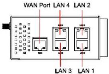
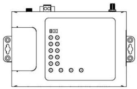
Panel Layout
OnCell 5004/5004-HSDPA/5004-HSDPA-JPS/5004-HSDPA-JPN
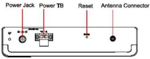
Top View
Front View

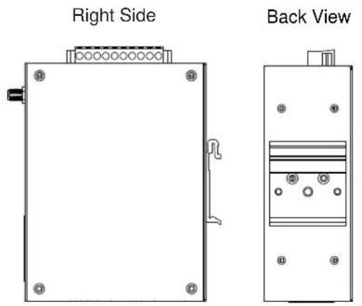
Side View
Rear View
OnCell 5104/5104-HSDPA/5104-HSDPA-JPS/5104-HSDPA-JPN
Top View
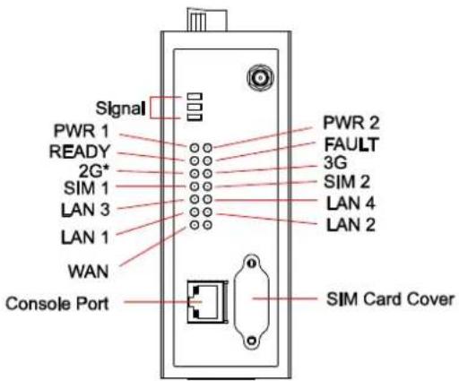
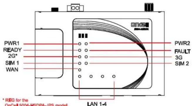
* REG for the OnCell 5004-HSDPA-JPS model
Front View

natural_image
Pure technical diagram of a vertical panel with mounting holes and internal components (no text or symbols)Back View
Bottom View
Left Side Right Side

natural_image
Simple line drawing of a rectangular frame with a clip and mounting bracket (no text or symbols)
natural_image
Pure technical diagram of a rectangular frame with mounting holes and a side clip, no text or symbols present.DIN-Rail and Rack Mounting
Wall or Cabinet Mounting
The OnCell 5004, OnCell 5004-HSDPA, and OnCell 5004-HSDPA-JPS device servers have built-in "ears" for attaching the device server to a wall or the inside of a cabinet. We suggest using two screws per ear to attach the device servers to a wall or the inside of a cabinet. The heads of the screws should be less than 6.0mm in diameter, and the shafts should be less than 3.5mm in diameter, as shown in the figure at the right.

natural_image
Pure electrical circuit lines without any symbols
natural_image
Pure electrical circuit lines without any symbolsDIN-Rail Mounting
DIN-rail attachments can be purchased separately to attach the OnCell 5104, OnCell 5104-HSDPA, and OnCell 5104-HSDPA-JPS to a DIN-Rail. When snapping the attachments to the DIN-Rail, make sure that the stiff metal springs are at the top.
Connecting the Hardware
This section describes how to connect the OnCell 5000 cellular IP-modem to a host PC or Ethernet devices for first time testing purposes. We cover SIM card Installation, Connecting the Power, Connecting the I/O Port, Connecting to the Network, LED Indicators, and Reset Button.
SIM Card Installation
In order to protect the SIM card, the SIM card slot is located inside the OnCell 5004 and 5104 series' housing. You will need to unscrew and remove the outer SIM card cover before installing or removing the SIM card.
OnCell 5004 Series OnCell 5104 Series

natural_image
Diagram of a SIM Card device with labeled components (no readable text or symbols beyond label)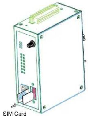
natural_image
Illustration of a SIM card device with ports and connectors (no text or symbols on the device itself)Connecting the Power
The dual power inputs that connect to the 4-pin power terminal block (2 terminals per power input) can be used to connect the OnCell 5104 to a variety of field power sources that support 12 to 48 VDC. The OnCell 5004 cellular routers have 1 power jack and 1 terminal block for connecting the power. After connecting the power wire to the OnCell's terminal block or power jack, the "PWR" LED will glow a solid green color to indicate that the system is ready.
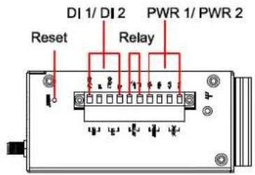
Connecting the I/O Port
The OnCell 5104 has six terminals on the terminal block for the I/O ports, with 4 terminals used for each input, and 2 terminals used for the output.
Digital Input
Power input levels determine the ON/OFF states of the digital inputs:
- On: +13 to +30 V for state "1"
- Off: +3 to -30 V for state "0"
Digital Output
• 1 relay output with current carrying capacity of 1 A @ 24 VDC.
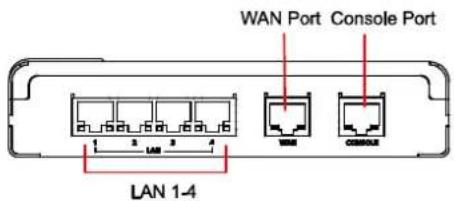
Connecting to the Network
Connect one end of the Ethernet cable to the OnCell's 10/100M Ethernet port and the other end of the cable to the Ethernet network. If the cable is properly connected, the OnCell will indicate a valid connection to the Ethernet in the following way:
• The Ethernet LED glows a solid green when connected to a 100 Mbps Ethernet network.
• The Ethernet LED glows a solid orange when connected to a 10 Mbps Ethernet network.
• The Ethernet LED flashes when Ethernet packets are being transmitted or received.
LED Indicators
The following table explains the LED indicators on the front panel of the OnCell 5004-HSDPA/5104-HSDPA:
| Type Color LED | Function | |
| PWR 1 Green Activ | ivation of DC Power | |
| Off Power is off, or power error condition exists. | ||
| PWR 2 Green Activ | ivation of DC Power | |
| Off Power is off, or power error condition exists. | ||
| 2G Amber 2G is connected | ||
| Off 2G is disconnected | ||
| 3G Amber 3G is connected (OnCell 5004-HSDPA and OnCell 5004-HSDPA-JPS) | ||
| Off 3G is disconnected(OnCell 5004-HSDPA and OnCell 5004-HSDPA-JPS) | ||
| REG Off Cannot register with cellular providers | ||
| Amber Registered with cellular provider | ||
| SIM1/2 Off SIM slot not in used | ||
| Amber Static on: SIM inserted and PIN code correct in used normally. | ||
| Ready Green Steady on: Software Ready.Blinking slowly (1 sec): The OnCell has been located by Ready the OnCell Search Utility. | ||
| off Power is off, or is booting up. | ||
| Fault Red Steady | on: Booting up, or IP fault.Blinking slowly (1 sec): Cannot get an IP address from the DHCP server | |
| off Power is off, or there is no error condition. | ||
| LAN 1-4 | Green Steady on: Software Ready.Blinking slowly (1 sec): Data transmission | |
| off Power is off, or is booting up. | ||
| Signal (3 LEDs) | Green Signal Level (at least 2 LEDs must illuminated for data transmission) | |

ATTENTION
REG LED:
- OFF: Cannot register with cellular providers using 3G mode, due to the wrong PIN code, or no cellular provider available. Signal LEDs will also be off.
• ON: Registered with cellular provider.
3G LED:
- OFF: Cannot register with cellular providers using UMTS/HSDPA mode due to the wrong PIN code (UMTS or HSDPA/signal LEDs off), no cellular provider available (UMTS or HSDPA/signal LEDs off), wrong APN (UMTS or HSDPA on/signal LEDs off), or wrong username/password (UMTS or HSDPA on/signal LEDs off).
• ON: Registered with cellular provider using UMTS/HSDPA mode. UMTS or HSDPA/Signal LEDs will be on.
Reset Button
Press and hold the Reset button for 5 sec to load factory defaults: Use a pointed object, such as a straightened paper clip or toothpick to press the reset button. This will cause the Ready LED to blink on and off. The factory defaults will be loaded once the Ready LED stops blinking (default LAN IP: 192.168.127.254).
When setting up the OnCell 5000 for the first time, the first thing you should do is configure the IP address. This chapter introduces the different methods that can be used to do this.
The following topics are covered in this chapter:
☐ Static and Dynamic IP Addresses
□ Factory Default IP Address
□ Configuration Options
OnCell Search Utility
Web Console
Telnet Console
Serial Console
Static and Dynamic IP Addresses
Determine whether your OnCell 5000 needs to use a static IP address or dynamic IP address (either DHCP or BOOTP application).
- If your OnCell 5000 is used in a static IP environment, you must assign a specific IP address using one of the tools described in this chapter.
- If your OnCell 5000 is used in a dynamic IP environment, the IP address will be assigned automatically from over the network. In this case, set the IP configuration mode to DHCP or BOOTP.

ATTENTION
Consult your network administrator on how to reserve a fixed IP address for your OnCell 5000 in the MAC-IP mapping table when using a DHCP Server or BOOTP Server. For most applications, you should assign a fixed IP address to your OnCell 5000.
Factory Default IP Address
The OnCell 5000 is configured with the following default private IP address:
192.168.127.254
Note that IP addresses that begin with "192.168" are referred to as private IP addresses. Devices configured with a private IP address are not directly accessible from a public network. For example, you would not be able to ping a device with a private IP address from an outside Internet connection. If your application requires sending data over a public network, such as the Internet, your OnCell 5000 will need a valid public IP address, which can be leased from a local ISP.
Configuration Options
OnCell Search Utility
You may configure your OnCell 5000 with the bundled OnCell Search Utility for Windows. Refer to Chapter 7, OnCell Search Utility, for details on how to install and use OnCell Search Utility.
Web Console
You may configure your OnCell 5000 using a standard web browser. Refer to Chapter 4, Using the Web Console, for details on how to access and use the OnCell 5000's web console.
Telnet Console
Depending on how your computer and network are configured, you may find it convenient to use network access to set up your OnCell 5000's IP address. This can be done using Telnet.

ATTENTION
Figures in this section were taken from the OnCell 5000 Telnet console.
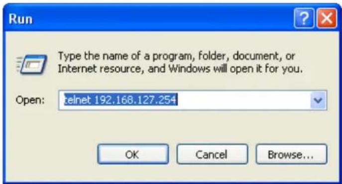
- From the Windows desktop, select Start → Run, and then type the following content in the Run window: telnet 192.168.127.254. If your IP address is different from the default setting, use your IP address instead. Click OK.
- The console terminal type selection is displayed, as shown below. Enter 1 for ansi/ vt100, and then press ENTER to continue.

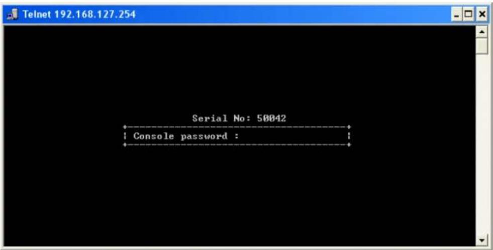
- The following window will only appear if the OnCell 5000 is password protected. Enter the console password if you are prompted to do so, and then press ENTER.
- Press N or use the arrow keys to select Network, and then press ENTER.
![Telnet 192.168.127.254 OnCell 5104 qnCell_5104_50042 1.0 Overview Basic [Network] Default Monitor sAve Restart Exit Examine/modify network settings Enter: select ESC: previous menu](/content/2026/05/1143689/images/d827826c408a7b3f2a26a14aa6203666163bc30fff05ef90cd80f26ccf96dc78.jpg)
- Press L or use the arrow keys to select LAN, and then press ENTER.
![Telnet 192.168.127.254 OnCell 5104 qnCell_5104_50042 1.0 NETWORK MENU [Lan] Cell. VAN Eth. VAN DNS Quit Examine/modify LAN settings Enter: select ESC: previous menu](/content/2026/05/1143689/images/2e3a60ee0d9bc274a3263f5f04efdfdccc84e8ae2e4afad7adbe4963e1b6540f.jpg)
- Use the arrow keys to move the cursor to IP address. Use the DELETE, BACKSPACE, or SPACE keys to erase the current IP address, and then type in the new IP address and press ENTER. Note that if you are using a dynamic IP configuration (BOOTP, DHCP, etc.), you will need to go to the IP configuration field and press ENTER to select the appropriate configuration.
![Telnet 192.168.127.254 OnCell 5104 qnCell_5104_50042 1.0 [Lan] Cell. VAN Eth. WAN DNS Quit Examine/modify LAN settings ESC: back to menu Enter: select IP address [192.168.127.254] Netmask [255.255.255.0 ] Port Enable Speed Flow Ctrl MDI/MDIX 0 [Yes] [Auto ] [Enable ] [MDIX] 1 [Yes] [Auto ] [Enable ] [MDIX] 2 [Yes] [Auto ] [Enable ] [MDIX] 3 [Yes] [Auto ] [Enable ] [MDIX]](/content/2026/05/1143689/images/0ae460440db8841651cc24e99e51bbae251f668733a4e99a30b6679c34f6e96c.jpg)
-
Press ESC twice to return to the previous page.
-
Press A or use the arrow keys to select Save and then press ENTER. Press ENTER again to confirm the save command.
![Telnet 192.168.127.254 OnCell 5104 qnCell_5104_50042 1.0 Overview Basic Network Default Monitor [sAve] Restart Exit Save current configuration to flash ROM ESC: back to menu Enter: select Enter to update, other key to cancel;](/content/2026/05/1143689/images/259730909aef7bc01330c63616766ee357c0605229387660cae8e5bac09f183f.jpg)
- Press R or use the arrow keys to select Restart and then press ENTER. Press ENTER again to restart the OnCell 5000.
![Telnet 192.168.127.254 OnCell 5104 qnCell_5104_50042 1.0 Overview Basic Network Default Monitor sAve [Restart] Exit Restart the server ESC: back to menu Enter: select Warning !!! Restart system will disconnect all ports and clear all status value Enter: continue ESC: cancel](/content/2026/05/1143689/images/cb8ff27332e56d0be9cf0022e5b7da1d6fd7ce97ddbc2ab47a33303f8d2b342b.jpg)
Serial Console
The OnCell 5000 can be configured through the serial console, which works the same as the Telnet console but is accessed through the RS-232 console port rather than over the network.
The following instructions and screenshots show how to enter the serial console using PComm Terminal Emulator, which is available free of charge as part of the PComm Lite suite. You may use a different terminal emulator utility, although the actual screenshots and procedure may vary slightly from the following instructions.
Before running PComm Terminal Emulator, use an RJ45 to DB9-F (or RJ45 to DB25-F) cable to connect the OnCell 5000's RS-232 console port to your PC's COM port (generally COM1 or COM2, depending on how your system is set up). After installing PComm Terminal Emulator, take the following steps to access the RS-232 console utility.
- Turn off the OnCell 5000's power, and then use a serial cable to connect the OnCell 5000's serial console port to your computer's RS-232 serial port.
- From the Windows desktop, select Start → All Programs → PComm Lite → Terminal Emulator.
-
The PComm Terminal Emulator window should appear. From the Port Manager menu, select Open (or click the Open icon).
-
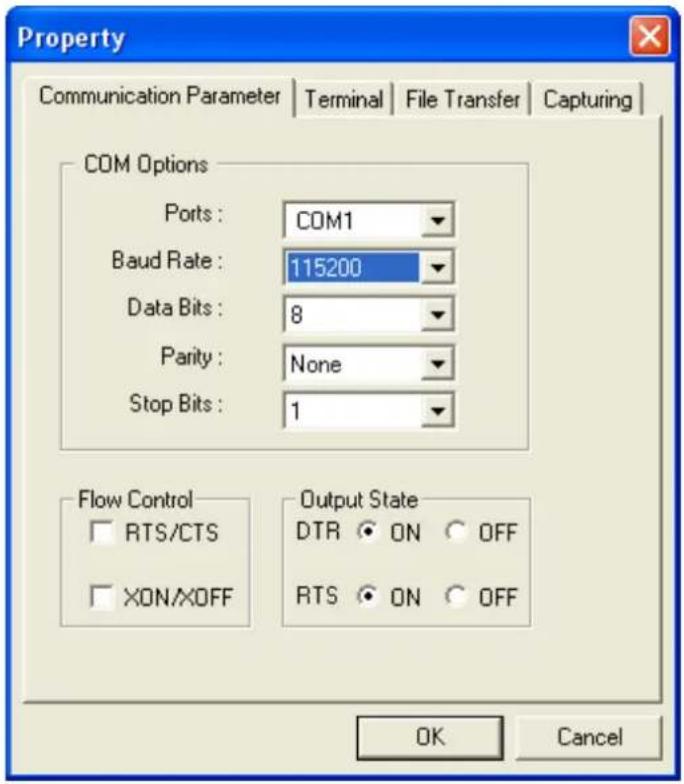
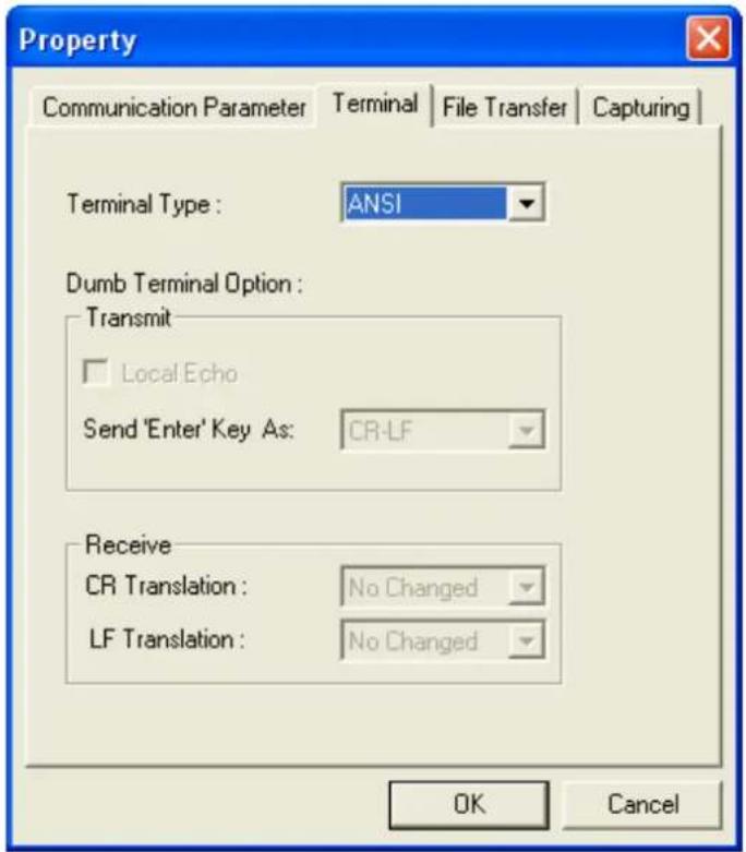
The Property window opens automatically. Select the Communication Parameter tab, and then select the appropriate COM port for the connection (COM1 in this example). Configure the parameters to 115200 for Baud Rate, 8 for Data Bits, None for Parity, and 1 for Stop Bits.
- From the Property window's Terminal page, select ANSI or VT100 for Terminal Type and then click OK.
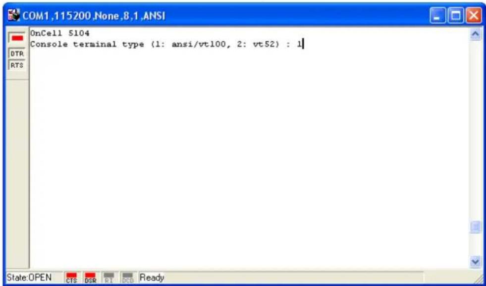
- If the OnCell 5000 has been set up for password protection, you will be prompted to enter the password. After you enter the password, or if password protection was not enabled, you will be prompted to select the terminal mode. Press 1 for ansi/ vt100 and then press ENTER.
- The main menu should appear. Once you are in the console, you may configure the IP address through the Network menu, just as with the Telnet console. Refer to steps 4 to 11 in the Telnet Console section to complete the initial IP configuration.
![COM1,115200,None,8,1,ANSI OnCell 5104 qnCell_5104_50042 1.0 Overview Basic [Network] Default Monitor sAve Restart Exit Examine/modify network settings Enter: select ESC: previous menu](/content/2026/05/1143689/images/0f4747370e4ecfae3e53a55f5328a5b9644114a8fb7a1cb6c18dce377843ca99.jpg)
In this chapter, we explain all aspects of the web-based console configuration utility. Moxa's easy-to-use management functions will help you set up your OnCell 5000 and allow you to maintain your wireless network easily.
The following topics are covered in this chapter:
□ Accessing the Web Console
□ Web Console Navigation
□ Basic Settings
Device Settings
Time Settings
□ Network Settings
LAN Settings
➢ LAN Port Configuration
Cellular WAN Settings
GuaranLink Settings
Ethernet WAN Settings
DNS Settings
DHCP Settings
Auto IP Report
□ Advanced Network Settings
▶ Firewall Settings
WAN IP Filter
Route Table
Accessing the Web Console
Open your web browser and enter 192.168.127.254 in the website address line. This is the default IP address for the OnCell 5000—if a new address has been assigned, enter the new address instead. Press ENTER to load the page.

ATTENTION
The examples and figures in this chapter use the OnCell 5000 factory default IP address of 192.168.127.254. If you have assigned a different IP address to your OnCell 5000, you will need to use that IP address. Refer to Chapter 3, Initial IP Address Configuration, for details on how to configure the IP address.
Enter the console password if prompted. The password will be transmitted with MD5 encryption over the Internet to ensure that the password cannot be easily intercepted by eavesdroppers.
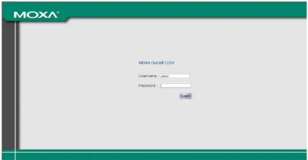
The OnCell 5000's web console will appear.
| Welcome to OnCell 5004/5104-HSDPA Series | |
| Model name | OnCell 5004-HSDPA |
| Serial No. | 60045 |
| Firmware version | 1.4 Build 10032318 |
| LAN IP address | 192.168.127.254 |
| LAN MAC address | 00:90:E8:06:00:46 |
| Cellular RSSI | 0 |
| Cellular WAN IP address | 0.0.0.0 |
| Cellular mode | N/A |
| Ethernet WAN IP address | 192.168.126.254 |
| Ethernet WAN MAC address | 00:90:E8:06:00:45 |
| Ethernet WAN speed | No link |
| WAN preference | Cellular |
| IMEI | 354114011190361 |
| Up time | 0 days 00h:17m:57s |
Web Console Navigation
The left panel of the OnCell 5000's web console is the navigation panel, and contains an expandable menu tree for navigating among the various settings and categories. When you click on a menu item in the navigation panel, the main window will display the corresponding options for that item. Configuration changes can then be made in the main window. For example, if you click on Basic Settings in the navigation panel, the main window will show a page of basic settings that you can configure.
You must click on the Submit button to keep your configuration changes. The Submit button is located at the bottom of every page that has configurable settings. If you navigate to another page without clicking the Submit button, your settings will be lost.
Changes will not take effect until they are saved and the OnCell is restarted! You may complete this in one step by clicking on the Save/Restart option after you submit a change. If you need to make several changes before restarting, you may save your changes without restarting by selecting Save Configuration in the navigation panel. If you restart the OnCell without saving your configuration, the OnCell will discard all submitted changes.
Basic Settings
The Basic Settings screen can be accessed from the navigation panel.
Device Settings
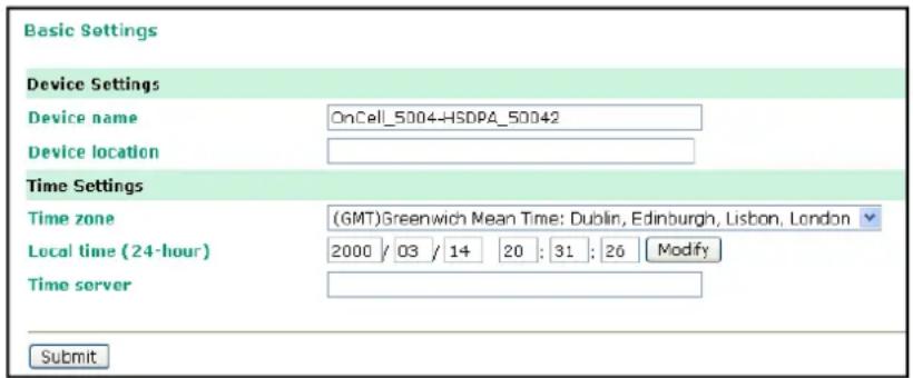
Device name: This is an optional text field for your own use; it does not affect the operation of the OnCell 5000, and can be used to help differentiate one OnCell 5000 device from another.
Device location: This is an optional text field for your own use; it does not affect the operation of the OnCell 5000, and is useful for assigning or describing the location of an OnCell 5000. If you need to manage multiple servers, you should use this field to indicate the precise physical location of each device.
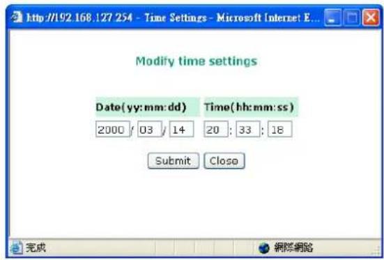
Time Settings
The OnCell 5000 has a built-in Real-Time Clock for time calibration functions. Functions such as Auto Warning Email or SNMP Trap can add real-time information to messages.
Before making any adjustments to the time, first select the correct time zone and submit the change. The console will display the real time according to the time zone. To modify the real time clock, click on Modify next to the Local time field. Once you submit the new time, the OnCell 5000's firmware will modify the GMT time based on your time zone and local time settings.

ATTENTION
There is a risk of explosion if the real-time clock battery is replaced with the wrong type!
The OnCell 5000's real time clock is powered by a lithium battery. We strongly recommend that you do not attempt to replace the lithium battery without help from a qualified Moxa support engineer. If you need to change the battery, please contact the Moxa RMA service team.
Time zone (default= GMT Greenwich Mean Time): This field shows the currently selected time zone and allows you to select a different time zone.
Local time: This field shows the time that you last opened or refreshed the browser. To set the local time for the OnCell 5000, click on the Modify button, update the date and time, and then click on submit.
Time server: The OnCell 5000 uses SNTP (RFC-1769) for auto time calibration. You may enter a time server IP address or domain name in this optional field. Once the OnCell 5000 is configured with the correct time server address, it will request time information from the time server every 10 minutes.
Network Settings
LAN Settings
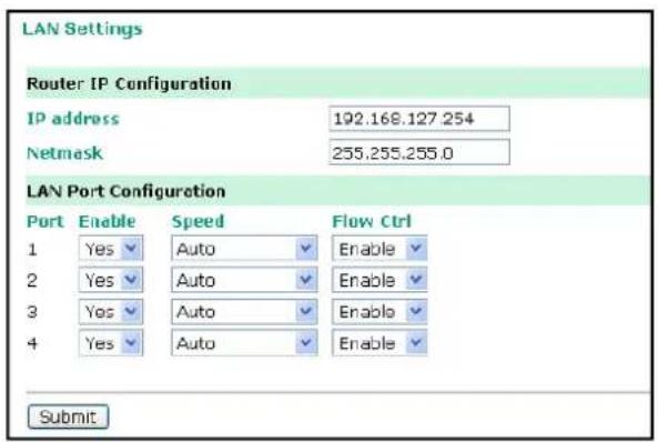
You can access LAN Settings by expanding the Network Settings item in the navigation panel. Use the LAN Settings page to assign the OnCell 5000's IP address, netmask, and other LAN Port configuration parameters.
Note: You must assign a valid IP address to your OnCell 5000 before it will work in your network environment. Your network system administrator should provide you with a unique IP address and related settings for your network. First-time users can refer to Chapter 3, Initial IP Address Configuration, for more information.
IP Address (default=192.168.127.254): Enter the IP address that is assigned to your OnCell 5000. All LAN ports on the OnCell 5000 will share this IP address. An IP address is a number assigned to a network device (such as a computer) as a permanent address on the network. Computers use the IP address to identify and talk to each other over the network. Choose a proper IP address that is unique and valid for your network environment.
Netmask (default=255.255.255.0): Enter the subnet mask. A subnet mask represents all of the network hosts at one geographic location, in one building, or on the same local area network. When a packet is sent out over the network, the OnCell 5000 will use the subnet mask to check whether the desired TCP/IP host specified in the packet is on the local network segment. If the address is on the same network segment as the OnCell 5000, a connection is established directly from the OnCell 5000. Otherwise, the connection is established through the given default gateway.
LAN Port Configuration
LAN Port Configuration settings are included to give the user control over Port Access, Port Transmission Speed, Flow Control, and Port Type (MDI or MDIX). An explanation of each configuration item is given below.
Enable (default=Yes):
| Option Description | |
| Yes Allows data transmission through the port. | |
| No Immediately shuts off port access. | |
Speed (default=Auto):
| Option Description | |
| Auto Allows the port to use the IEEE 802.3u protocol to negotiate with connected devices. The port and connected devices will determine the best speed for that connection. | |
| 10Mbps Half Choose one of these fixed speed options if the opposing Ethernet device has trouble auto-negotiating for line speed. | |
| 10Mbps Full | |
| 100Mbps Half | |
| 100Mbps Full | |
Flow Ctrl (default=Enable):
This setting enables or disables the flow control capability of this port when the "speed" setting is in "auto" mode. The final result will be determined by the "auto" process between the OnCell and connected device.
| Option Description | |
| Enable Enables the flow control capability of this port when in auto-nego mode. | |
| Disable Disables the flow control capability of this port when in auto-nego mode. | |
Cellular WAN Settings
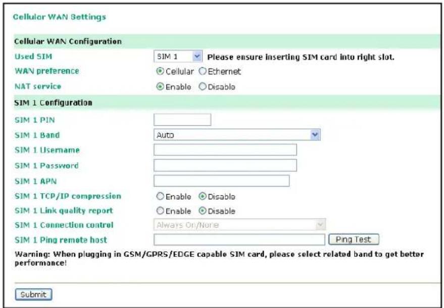
From the left navigation panel, click Network Settings → Cellular WAN Settings to configure the SIM card Settings. The various configuration items are described below:
WAN Preference (default=Cellular): Select either cellular or Ethernet. Note that the WAN preference option on the Ethernet WAN settings page (see below) will be updated automatically.
Note: You need to select one of the two WAN preferences. If the line is disconnected, the router will not automatically switch to the other WAN preference.
NAT service (default=Enable): If you Enable NAT service, LAN-side applications will be able to link to WAN-side applications.
Used SIM: Select the SIM card number that has been used, and please ensure inserting SIM card into right slot.
The following information is only show SIM 1 configuration, If SIM 2 available, please follow the same setting as well
SIM1 PIN: This is a pin code that locks the SIM card until you enter the correct code. Use the pin to protect your account. The default code is set by the Service Provider. Note that a cell phone must be used to change the PIN.
Band (default=Auto): The GSM/GPRS/EDGE/UMTS/HSDPA band will be detected automatically.
Username: This is the user ID account.
Password: This is the user password.
APN: Before using the GPRS, an APN (Access Point Name) must be configured as a modem initialization command.
TCP/IP compression (default=Disable): Use this field to indicate whether the remote user's application requests compression.
Link quality report (the default is set to "Disable"): Set this field to "Enable" for the following:
(1) Automatic disconnection if the link noise of the connection exceeds a user-defined threshold.
GuaranLink Settings
Overview
Connection failures of wireless connections can be caused by a number of different factors, including loss of cellular signal, interferences or termination by the operator for unknown reasons. Typically, cellular routers will not be alerted when a connection is terminated due to inactivity. And maintaining a stable cellular connection is important for a number of obvious reasons. This is why OnCell cellular routers offer the GuaranLink function, which ensures your wireless connection will be there whenever you need it.
Background
- "Register to network" and "Establish PPP with ISP" are two steps for establishing connection with the ISP.
- If GuaranLink determines that the OnCell cannot establish connection with the ISP, it reboots the OnCell in order to allow the OnCell to retry the connection once rebooted.
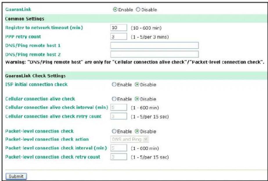
Common Settings
- GuaranLink (default=Disable): Enable this setting to start the GuaranLink function.
- Register to network timeout (min) (default=10): This setting is to specify how long GuaranLink should wait to register to the network before the OnCell reboots itself.
- PPP retry count (default=3 mins) This setting is to specify how many times GuaranLink should retry to establish PPP with the ISP before OnCell reboots itself.
- DNS/ Ping remote host 1 and DNS/ Ping remote host 2: This setting is for "Cellular connection alive check" and "Packet-level connection check." It specifies the target host of the DNS lookup and Ping action. It could be either a domain name or an IP address.
GuaranLink Check Settings
- ISP initial connection check (default=Disable): This function is to ensure that the OnCell can establish connection with an ISP after it reboots.
- Cellular connection alive check (default=Disable): Some ISPs may disable the connection if there is no data transmitted in a specific period of time, depending on the ISP's settings. This function ensures that the cellular connection will be kept alive even if no data is transmitted for a period of time by performing the check action of DNS lookup or ping action of DNS/Ping remote host 1 or DNS/Ping remote host 2. If the check action fails after the retry count number specified in "Cellular connection alive check retry count", the OnCell will re-establish a connection with the ISP.
- Cellular connection alive check interval (min) (default=5 min): This setting specifies the idle time before GuaranLink performs the check action.
- Cellular connection alive check retry count (default=3 sec): This setting specifies the number of attempts to reach the remote target(s) before the OnCell re-establishes a connection.
- Packet-level connection check (default=Disable): This function checks if the cellular network can be accessed by performing the check action of lookup DNS or ping action of DNS/Ping remote host 1 or DNS/Ping remote host 2. If the check action fails after the retry count number specified in "Packet-level connection check retry count." the OnCell will re-establish a connection with ISP.
- Packet-level connection check action (default=DNS and PING): This setting specifies whether the check action is successful when both of the DNS lookup and the ping action succeed, or if it is successful even if only one of them succeed.
- Packet-level connection check interval (min) (default=5 min): This setting specifies the interval between two check actions.
- Packet-level connection check retry count (default=3 sec): This setting specifies the number of attempts to reach the remote target(s) before the OnCell re-establishes a connection.
Ethernet WAN Settings
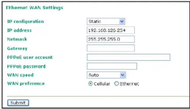
You can access Network Settings → Ethernet WAN Settings by expanding the item in the navigation panel. Ethernet WAN Settings is where you assign the OnCell 5000's IP address, netmask, Gateway, and other parameters for the Ethernet interface.
Note: You must assign a valid WAN IP address to your OnCell 5000 before it will work in your network environment. Your network system administrator should provide you with a unique IP address and related settings for your network.
IP configuration (default=Static): You can choose from four possible IP configuration modes:
| Mode Description | |
| Static User-defined IP address, netmask, and gateway | |
| DHCP DHCP server-assigned IP address, netmask, gateway, and DNS | |
| PPPoE Your ISP will provide you with a username and password. This option is typically used for DSL services | |
| DHCP/BOOTP DHCP server-assigned IP address, netmask, gateway, and DNS, or BOOTP server-assigned IP address (if the DHCP server does not respond) | |
| BOOTP BOOTP server-assigned IP address | |
IP Address (default=192.168.126.254): Enter the WAN IP address that the OnCell 5000 will use to connect to the internet.
Netmask (default=255.255.255.0): Enter the subnet mask. A subnet mask represents all of the network hosts at one geographic location, in one building, or on the same local area network. When a packet is sent out over the network, the OnCell 5000 will use the subnet mask to check whether the desired TCP/IP host specified in the packet is on the local network segment. If the address is on the same network segment as the OnCell 5000, a connection is established directly from the OnCell 5000. Otherwise, the connection is established through the given default gateway.
Gateway: Enter the IP address of the gateway if applicable. A gateway is a network computer that acts as an entrance to another network. Usually, the computers that control traffic within the network or at the local Internet service provider are gateway nodes. The OnCell 5000 needs to know the IP address of the default gateway computer in order to communicate with the hosts outside the local network environment. For correct gateway IP address information, consult the network administrator.
PPPoE user account: If your ISP uses a PPPoE connection, enter the user account name here. This option is typically used for DSL services.
PPPoE password: Enter your password.
WAN speed (default=Auto):
| Option Description | |
| Auto Allows the port to use the IEEE 802.3u protocol to negotiate with connected devices. The port and connected devices will determine the best speed for that connection. | |
| 10Mbps Half Choose one of these fixed speed options if the opposing Ethernet device has trouble auto-negotiating for line speed. | |
| 10Mbps Full | |
| 100Mbps Half | |
| 100Mbps Full | |
WAN Preference (default=Cellular): You must select either one of the WAN interface for data transmission. Note that the WAN preference option on the Cellular WAN settings page (see above) will be updated automatically.
Note: You need to select one of the two WAN preferences. If the line is disconnected, the router will not automatically switch to the other WAN preference.
DNS Settings
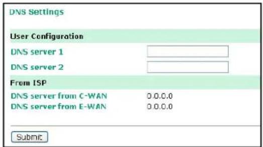
DNS server 1: This is an optional field since the DNS server automatically obtains the DNS server's IP address from C-WAN OR E-WAN. If your network has access to a DNS server, you may choose to enter the DNS server's IP address in this field. This allows the OnCell 5000 to use domain names instead of IP addresses to access hosts.
The Domain Name System (DNS) is used to identify Internet domain names and to translate the names into IP addresses. A domain name is an alphanumeric name, such as www.moxa.com, that it is usually easier to remember than the numeric IP address. A DNS server is a host that translates this kind of text-based domain name into the actual IP address used to establish a TCP/IP connection.
When the user wants to visit a particular website, the user's computer sends the domain name (e.g., www.moxa.com) to a DNS server to request that website's numeric IP address. When the IP address is received from the DNS server, the user's computer uses that information to connect to the website's web server. The OnCell 5000 plays the role of a DNS client, in the sense that it actively queries the DNS server for the IP address associated with a particular domain name. The following functions in the OnCell 5000's web console support the use of domain names in place of IP addresses: Time Server, Destination IP Address (in TCP Client mode), Mail Server, SNMP Trap Server, and SMTP Server.
DNS server 2: This is an optional field. The IP address of another DNS server may be entered in this field for times when DNS server 1 is unavailable.
DNS server form C-WAN: Normally, the DNS server's IP address is automatically obtained through the cellular network. The OnCell will use the DNS server's C-WAN or E-WAN's IP address as its first priority.
DNS server form E-WAN: Normally, the DNS server's IP address is automatically obtain through the Ethernet network. The OnCell will use the DNS server's C-WAN or E-WAN's IP address as its first priority.
DHCP Settings
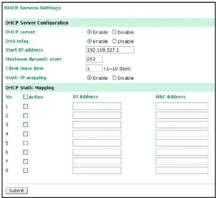
DHCP (default=Enable): DHCP stands for Dynamic Host Control Protocol. When you enable the DHCP Server, it will automatically assign an IP address to the computers on the LAN/private network. Be sure to set your computers to be DHCP clients by setting their TCP/IP settings to "Obtain an IP Address Automatically." When you turn your computers on, they will automatically load the proper TCP/IP settings provided by the OnCell 5000. The DHCP Server will automatically allocate an unused IP address from the IP address pool to the requesting computer. You must specify the starting and ending address of the IP address pool.
DNS relay (default=Enable): If enabled, your computers will use the router as a DNS server. If disabled, the DNS server information will be transferred from your ISP to your computers.
Start IP address: Enter the starting IP addresses for the DHCP server's IP assignment.
Note: If you assign static IP addresses to your computers or devices, make sure the IP addresses are outside of this range or you may have an IP conflict.
Client lease time: The length of time for the IP address lease. Enter the Lease time in days.
Static IP mapping: If enabled, the mapping list allows you to assign specific IP addresses to specific MAC addresses, provided the IP addresses are in the range specified under DHCP Server Configuration.
Auto IP Report
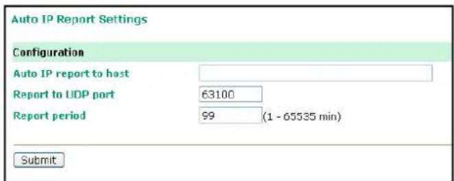
Auto IP report to host: Reports generated by the Auto report function will be sent automatically to this IP address or host name.
Report to UDP port (default=63100): This is the UDP port number assignment for the serial port on the OnCell 5000.
Report period (default=99): You can use this option to set the automatic report time.
Advanced Network Settings
Firewall Settings
Virtual Server Settings
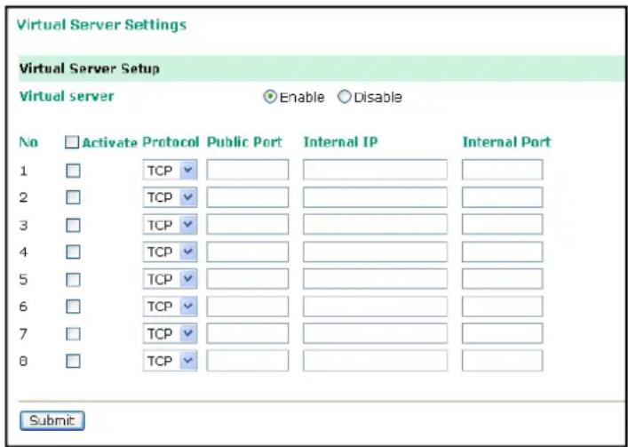
Virtual Server Settings (default=Disable): This function allows remote users to access the Host or FTP services via a public IP address, and automatically redirects them to local servers in the LAN (Local Area Network).
The OnCell firewall feature filters out unrecognized packets to protect your LAN network when computers networked with the OnCell are hidden from public view. If you wish, you can make some of the LAN computers accessible from the Internet by enabling Virtual Server. Depending on the requested service, the OnCell redirects the external service request to the appropriate server within the LAN network.
The OnCell is also capable of port-redirection, which means that traffic coming in to a particular port may be redirected to a different port on the server computer.
Public Port: The public port is the port seen from the Internet side.
Internal IP: Enter the IP address of the host on your local network that you want to link the incoming service to.
Internal Port: The internal port is the port being used by the application on the host within your local network.
WAN IP Filter
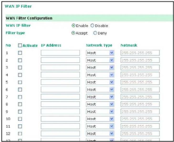
The OnCell 5000 uses an IP address-based filtering method to control access to its Ethernet ports. The WAN IP Filter allows you to restrict network access to the OnCell 5000. Access is controlled by IP address. When the WAN IP Filter list is enabled, a WAN's IP address must be listed in order to gain access to the OnCell 5000. You may add a specific address or range of addresses by using a combination of IP address and netmask, as follows:
Filter Type: If you select Accept, the WAN IPs that you enter will be allowed to access the OnCell 5000. If you select Deny, the WAN IPs that you enter will be denied access to the OnCell 5000.
IP Address: This is the WAN IP address or cellular network address that you would like to filter.
Netmask type: Commonly used network classes are indicated below:
| Network Type Netmask | |
| Host | 255.255.255.255 |
| Class A 255.0.0.0 | |
| Class B 255.255.0.0 | |
| Class C 255.255.255.0 | |
| User Define --- |
Netmask: This is the destination network's netmask.
Route Table
You can access the Route Table by expanding Advanced Network Settings in the navigation panel. Use the route table to configure how the OnCell 5000 will connect to an outside network.
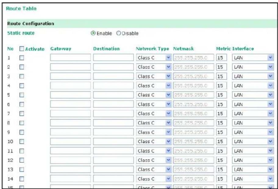
You are allowed up to 16 entries in the route table. For each entry, you must provide the gateway, destination, netmask type, netmask, metric hops, and interface.
Gateway: This is the IP address of the next-hop router.
Destination: This is the host's IP address or the network address of the route's destination.
Netmask type: Commonly used network classes are indicated below:
| Network Type Netmask | |
| Host | 255.255.255.255 |
| Class A 255.0.0.0 | |
| Class B 255.255.0.0 | |
| Class C 255.255.255.0 | |
| User Define – |
Netmask: This is the destination network's netmask.
Metric: You may use this optional field to enter the number of hops from the source to the destination. This allows the OnCell 5000 to prioritize the routing of data packets if there is more than one router available to reach a given destination.
Interface: This is the network interface to which the packet must be sent.
In this chapter, we describe the OnCell 5000's system management settings. The same configuration options are also available through the Telnet and serial console.
The following topics are covered in this chapter:
□ Misc. Network Settings
SNMP Agent Settings
DDNS Configuration
□ Auto Warning Settings
Event Settings
E-mail Alert
SNMP Trap
SMS Alert
□ Maintenance
Console Settings
PING Test
System Log Settings
➢ Firmware Upgrade
Configuration Import/Export
Load Factory Defaults
Change Password
□ Certificate
Ethernet SSL Certificate Import
▶ Certificate/Key Delete
□ System Monitoring
▶ Network Connections
Network Statistics
Routing
DHCP Client List
Internet Sessions List
System Log
Dout State
➢ Din and Power Status
□ Save Configuration
□ Restart
Restart System
Misc. Network Settings
SNMP Agent Settings
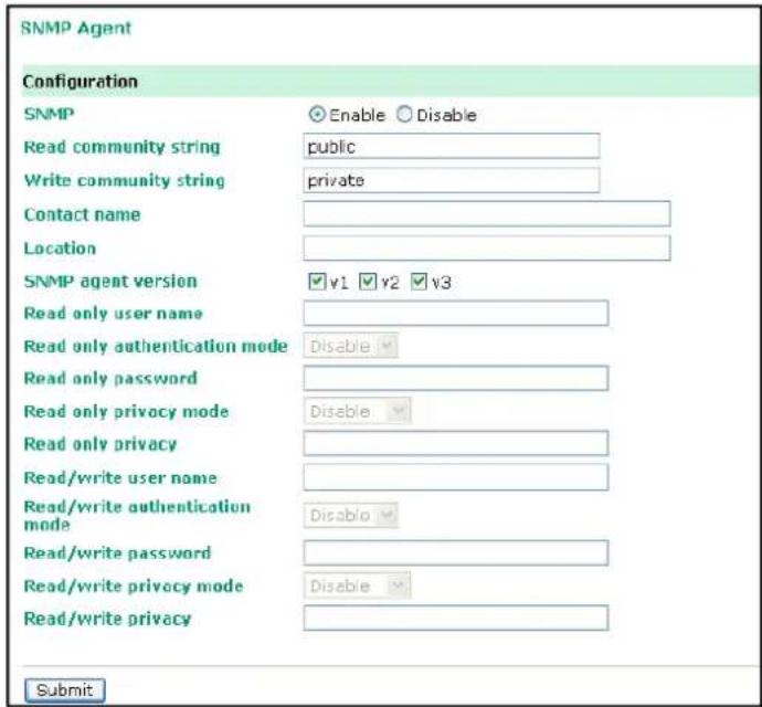
SNMP: To enable the SNMP Agent function, select the Enable option, and enter a community name (e.g., public).
Read community string (default=public): This is a text password that is used to weakly authenticate queries to agents of managed network devices.
Write community string (default=private): This is a text password that is used to weakly authenticate changes to agents of managed network devices.
Contact name: The optional SNMP contact information usually includes an emergency contact name and telephone or pager number.
Location: Use this optional field to specify the location string for SNMP agents such as the OnCell 5000. This string is usually set to the street address where the OnCell 5000 is physically located.
SNMP agent version: The OnCell 5000 supports SNMP V1, V2, and V3.
Read-only and Read/ Write Access Control
The following fields allow you to define user names, passwords, and authentication parameters for two levels of access: read-only and read/write. The name of the field will indicate which level of access it refers to. For example, Read only authentication mode allows you to configure the authentication mode for read-only access, whereas Read/write authentication mode allows you to configure the authentication mode for read/write access. For each level of access, you may configure the following:
User name: Use this optional field to identify the user name for the specified level of access.
Authentication mode (default=Disable): Use this field to select MD5 or SHA as the method of password encryption for the specified level of access, or to disable authentication
Privacy mode (default= Disable): Use this field to enable or disable DES_CBC data encryption for the specified level of access.
Password: Use this field to set the password for the specified level of access.
Privacy: Use this field to define the encryption key for the specified level of access.
DDNS Configuration
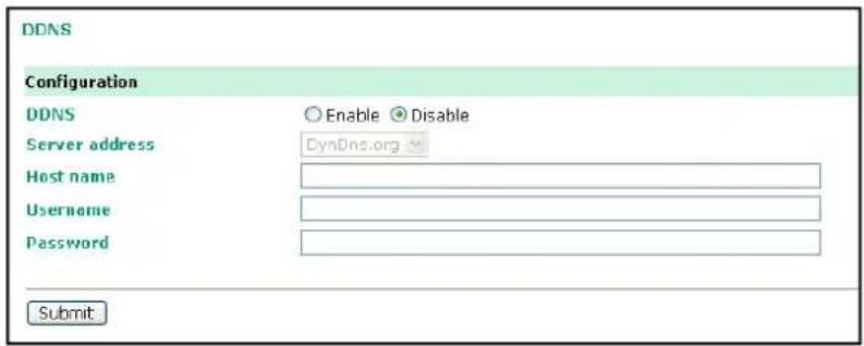
DDNS (default= Enable): The Dynamic Domain Name System is a method of keeping a domain name linked to a changing IP Address. Check the box to enable DDNS.
Server address: Choose your DDNS provider from the drop down menu.
Host name: Enter the Host Name that you registered with your DDNS service provider.
Username: Enter the Username for your DDNS account.
Password: Enter the Password for your DDNS account.
Auto Warning Settings
Event Settings
| Event Settings | |||
| System Event | |||
| Cold start | Trap | SMS | |
| Warm start | Trap | SMS | |
| Network Event | |||
| Ethernet link down | Dout SMS | ||
| Config Event | |||
| Console(web/text) login auth fail | Trap | SMS | |
| IP changed | SMS | ||
| Password changed | SMS | ||
| Power Event | |||
| Power 1 fail | Dout SMS | ||
| Power 2 fail | Dout SMS | ||
| Din Event | |||
| Din 1 turn on (trigger) | Dout SMS | ||
| Din 1 turn off (trigger) | Dout SMS | ||
| Din 2 turn on (trigger) | Dout SMS | ||
| Din 2 turn off (trigger) | Dout SMS | ||
| Cellular Module Event | |||
| Cell. module fail | Dout SMS | ||
| Cell. close temperature range | Dout SMS | ||
| Cell. over temperature range | Dout SMS | ||
On the Event Settings page, you may configure how administrators are notified of certain system, network, configuration, power, Din, and cellular module events. Depending on the event, different options for automatic notification are available, as shown above. Mail refers to sending an e-mail to a specified address. Trap refers to sending an SNMP Trap. Dout is available on the network, power, Din, and cellular module event. SMS refers to sending a message to a specified phone number.
NOTE If you select "enable for SMS," the receiver will receive the message in the following format:
[modelName] alert (S/N: [serial number], LAN: [LAN IP], [LAN MAC Address]):
(C-WAN/E-WAN/P-WAN: [WAN IP]): (yyyy-mm-dd hh:mm:ss) [message]
C-WAN: x.x.x.x indicates the cellular WAN IP address
E-WAN: x.x.x.x indicates the Ethernet WAN IP address and "P-WAN: x.x.x.x" indicates the preferred WAN IP address.
Cold start: This refers to starting the system from a power off state, or after upgrading the firmware
Warm start: This refers to restarting the OnCell 5000 without turning the power off.
Ethernet link down: These settings configure the OnCell 5000 to change the status of the relay output and SMS if the specified connection goes down.
Console (web/ text) login authentication failure: This field refers to failed attempts to log in to a WEB/Console/Telnet/OnCell Central using a password.
IP changed: With this IP address change, the OnCell 5000 will send an email or SMS warning after it reboots.
Password changed: With this option selected, the OnCell 5000 will attempt to send an e-mail or SMS warning after it reboots with a new console password. If the OnCell 5000 is unable to send an e-mail or SMS message to the mail server within 15 seconds, it will still reboot without sending the e-mail or SMS.
Power event: The OnCell 5000 provides two DC power inputs for redundancy. If either power fails, the OnCell 5000 will attempt to send an e-mail warning, relay output, or SMS.
Din event: When the status of digital input 1 or 2 is changed, the OnCell 5104 series will attempt to send an e-mail, trigger the digital output, or send an SMS.
Cell. module fail: When the cellular module fails to function, the OnCell 5000 will attempt to send an e-mail, or trigger the digital output to inform users.
Cell. close temperature range: When the temperature on the cellular module inside the OnCell 5000 is close to the upper or lower limit, the OnCell 5000 will attempt to send an e-mail, trigger the digital output, or send an SMS message to inform users.
Cell. over temperature range: When the temperature on the cellular module inside the OnCell 5000 is outside the normal temperature range, the OnCell 5000 will attempt to send an e-mail, or trigger the digital output to inform users.
E-mail Alert
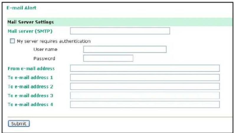
The E-mail Alert settings determine how e-mail warnings are sent for system and serial port events. You may configure up to 4 e-mail addresses to receive automatic warnings.

ATTENTION
Consult your Network Administrator or ISP for the proper mail server settings. The Auto warning function may not work properly if it is not configured correctly. The OnCell 5000's SMTP AUTH supports LOGIN, PLAIN, and CRAM-MD5 (RFC 2554).
Mail server: This field is for your mail server's domain name or IP address.
User name: This field is for your mail server's user name, if required.
Password: This field is for your mail server's password, if required.
From e-mail address: This is the e-mail address from which automatic e-mail warnings will be sent.
To e-mail address 1 to 4: This is the e-mail address or addresses to which the automatic e-mail warnings will be sent.
SNMP Trap
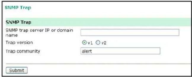
SNMP trap server IP: Use this field to indicate the IP address to use for receiving SNMP traps.
Trap version (default=v1): Use this field to select the SNMP trap version.
Trap community (default=alert): Use this field to designate the SNMP trap community.
SMS Alert
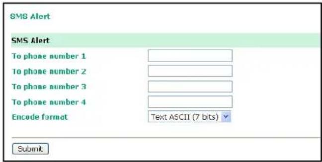
To phone number 1 to 4: This is the phone number to which the automatic warnings message will be sent.
Encode format:
| SMS Data Format | |
| Text ASCII (7 bits) (default) 7 bits | text format (160 bytes per packet) |
| Binary 8 bits binary (140 bytes per | packet) |
| Unicode 16 bits Unicode (UCS2) for | mat (70 bytes per packet) |
Maintenance
Console Settings
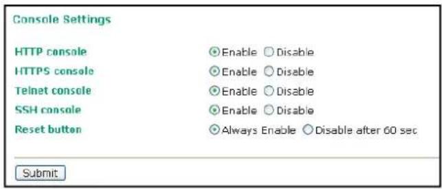
On this screen, access to different OnCell 5000 configuration console options (HTTP, HTTPS, Telnet, SSH) can be enabled or disabled. Refer to Change Password later in this chapter for more information on passwords.
Reset button (default=Always Enable): Select "Always Enable" to activate the reset button. Use the "Disable after 60 sec" option to avoid resetting the server when the reset button is pressed accidentally.
PING Test
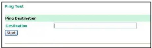
You can ping an IP address from the OnCell 5000 web console in order to test the Ethernet connection. Enter the IP address or domain name in the Destination field to make sure the connection is OK.
System Log Settings
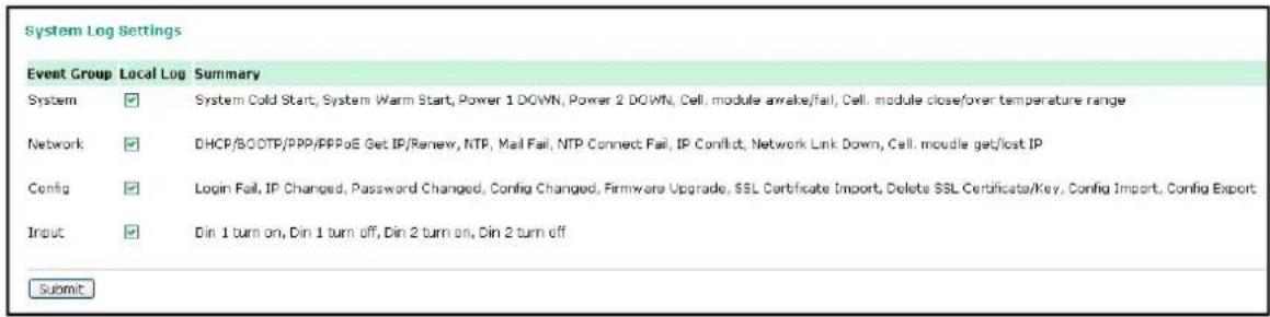
System Log Settings allows the administrator to customize which network events are logged by the OnCell 5000. Events are grouped into five categories, known as event groups, and the administrator selects which groups to log under Local Log. The actual system events that would be logged for each system group are listed under summary. For example, if System was enabled, then System Cold Start events and System Warm Start events would be logged.
| Group Event | |
| System System Cold Start | , System Warm Start, Power 1 DOWN, Power 2 DOWN, Cell. module awake/fail, Cell. module close/over temperature range |
| Network DHCP/BOOTP Get | IP/Renew, NTP, Mail Fail, NTP Connect Fail, IP Conflict, Network Link Down, Cell. module get/lost IP |
| Config Login Fail, IP Changed, Password Changed, Config Changed, Firmware Upgrade, SSL Key Import, Config Import, Config Export | |
| Input Din 1 turn on, Din | 1 turn off, Din 2 turn on, Din 2 turn off |
Firmware Upgrade
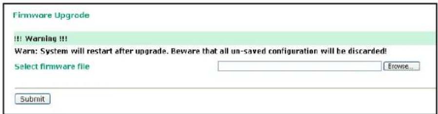
The OnCell 5000's firmware can be upgraded though the web console or the OnCell Search Utility. If you have made any changes to your configuration, remember to save the configuration first before upgrading the firmware. Please refer to Save Configuration later in this chapter for more information. Any unsaved changes will be discarded when the firmware is upgraded. To upgrade the firmware, simply enter the file name and click Submit. The latest firmware can be downloaded from www.moxa.com.
Configuration Import/ Export
The OnCell 5000 can share or back up its configuration by exporting all settings to a file.
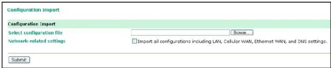
To import a configuration, go to System Management → Maintenance → Configuration Import. Enter the configuration file path/name and click Submit. The OnCell 5000's configuration settings will be updated according to the configuration file. If you also wish to import the IP configuration (i.e., the OnCell 5000's IP address, netmask, gateway, etc.), make sure that Import all configurations including IP configurations is checked.
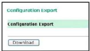
To export a configuration, go to System Management → Maintenance → Configuration Export and click Download. A standard download window will appear to allow you to download the configuration into a file and location of your choice.
Load Factory Defaults
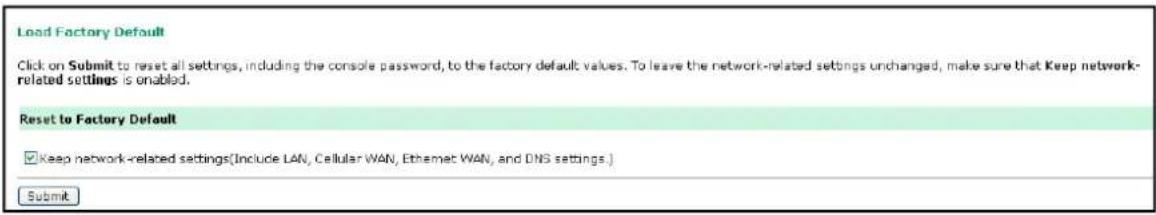
This function will reset all of the OnCell 5000's settings to the factory default values. All previous settings, including the console password will be lost. If you wish to keep the OnCell 5000 IP address, netmask, and other IP settings, make sure Keep IP settings is checked before loading the factory defaults.
Change Password
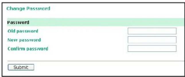
For all changes to the OnCell 5000's password protection settings, you will first need to enter the old password. Leave this blank if you are setting up password protection for the first time. To set up a new password or change the existing password, enter the password under both New password and Confirm password. To remove password protection, leave the New password and Confirm password boxes blank.

ATTENTION
If you forget the password, the ONLY way to configure the OnCell 5000 is by using the reset button on the OnCell 5000's casing to load the factory defaults.
Before you set a password for the first time, it is a good idea to export the configuration to a file when you have finished setting up your OnCell 5000. Your configuration can then be easily imported back into the OnCell 5000 if you need to reset the OnCell 5000 due to a forgotten password or for other reasons. Please refer to the section on Configuration Import/Export earlier in this chapter for more details.
Certificate
Ethernet SSL Certificate Import
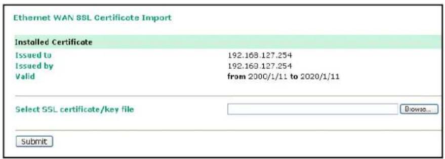
SSL certificate is used to ensure that the website you are accessing is the one you trust, and to encrypt the data transmitted between you and the website. The SSL certificate contains unique, authenticated information about the certificate owner. It is issued by a Certificate Authority (CA), such as VeriSign, that verifies the identity of the certificate owner.
The OnCell 5000 will generate a new SSL certificate whenever a new IP is used. However, the SSL certificate is issued by the OnCell itself. If you would like to import an SSL certificate issued by a primary CA, you can do it from the "Ethernet SSL Certificate Import" page.
Certificate/ Key Delete

You can delete an SSL certificate on this page. To do so, select the Delete option and then click on the Submit button.
System Monitoring
Network Connections
Go to System Monitoring under Network Connections to view network connection information.
| Protocol | Recv-Q | Send-Q | Local Address | Foreign Address | State |
| TCP | 0 | 0 | 192.168.127.254:8000 | *.* | LISTEN |
| TCP | 0 | 0 | 192.168.127.254:4900 | *.* | LISTEN |
| TCP | 0 | 0 | 192.168.127.254:14900 | *.* | LISTEN |
| TCP | 0 | 0 | 192.168.127.254:60 | *.* | LISTEN |
| TCP | 0 | 0 | 192.168.127.254:443 | *.* | LISTEN |
| TCP | 0 | 0 | 192.168.127.254:23 | *.* | LISTEN |
| TCP | 0 | 0 | 192.168.127.254:22 | *.* | LISTEN |
| TCP | 0 | 0 | 192.168.127.254:80 | 192.168.127.111:1054 | ESTAB |
| TCP | 0 | 0 | 192.168.127.254:60 | 192.168.127.111:1135 | ESTAB |
Network Statistics
Go to System Monitoring under Network Statistics to view network statistics.
| Network Statistics | ||||||
| Auto refroch | ||||||
| ETHERNET | Received | 0 | Sent | 12 | ||
| Received | 3168 | Sent | 6169 | |||
| IP | RDiscard | 0 | SNoRoute | 0 | SDiscard | 0 |
| EmHeader | 0 | ErrProto | 0 | EmAddr | 0 | |
| Received | 0 | Sent | 0 | |||
| ICMP | RechoReq | 0 | SEchoReq | 0 | ||
| REchoRply | 0 | SEchoRply | 0 | |||
| UDP | Received | 91 | Sent | 18 | ||
| EmHeader | 0 | ErrPorts | 0 | |||
| Received | 3070 | Sent | 6144 | |||
| TCP | EmHeader | 0 | ErrPorts | 0 | ReSent | 1 |
| CumEstab | 2 | Opens | 34 | |||
Routing
Go to System Monitoring under Routing to display the routing information.
| Routing | ||||||
| Auto refresh | ||||||
| Current Routing | ||||||
| Iface | Destination | Gateway/HA | Netmask | Metric | Flag | Use |
| LAN | 192.168.127.0 | 192.168.127.254 | 255.255.255.0 | 1 | U+ | 6319 |
| WAN-E | 192.168.126.0 | 192.168.126.254 | 255.255.255.0 | 1 | D | 9 |
Possible flags include:
• U: route is up
• D: route is down
• G: use gateway
• +: default gateway
- T: static route
• H: target is a host
DHCP Client List
The DHCP Client List shows all the clients that require and have successfully received IP assignments. You can click the Refresh button to refresh the list.
| DHCP Client List | ||||
| ☑ Auto refresh | ||||
| No | MAC Address | Assigned IP | Hostname | Expires |
Internet Sessions List
| Internet Session List | |||||||
| Auto refresh | |||||||
| No | Local | NAT Port | Internet | Protocol | State | Direction | Time Out |
The Internet Sessions page displays full details of active Internet sessions through your router. An Internet session is a conversation between a program or application on a LAN-side computer and a program or application on a WAN-side computer/device.
System Log
This option displays the system log. You may click Select all to select the entire log if you wish to copy and paste the contents into a text file.
![System Log System Log 2000/01/14 03:45:14 [Network] JP Conflict 2000/01/14 03:45:40 [Network] Ethernet WAN Link Down 2000/01/14 03:46:07 [Network] Ethernet WAN Link Down 2000/01/14 03:46:30 [Network] Ethernet 4 Link Down 2000/01/14 03:47:04 [System] Power 1 DOWN 2000/01/14 03:47:04 [System] Power 2 DOWN 2000/01/14 03:47:04 [System] System Cold Start 2000/01/14 03:49:04 [System] Power 1 DOWN 2000/01/14 03:49:04 [System] Power 2 DOWN 2000/01/14 03:49:04 [System] System Cold Start 2000/01/14 03:50:04 [System] Power 1 DOWN 2000/01/14 03:50:04 [System] Power 2 DOWN 2000/01/14 03:50:04 [System] System Cold Start 2000/01/14 03:50:04 [System] Power 1 DOWN 2000/01/14 03:50:04 [System] Power 2 DOWN 2000/01/14 03:50:04 [System] System Cold Start 2000/01/15 04:20:04 [System] Power 1 DOWN 2000/01/15 04:20:04 [System] Power 2 DOWN 2000/01/15 04:21:21 [Network] Ethernet 4 Link Down Select all Clear log Refresh](/content/2026/05/1143689/images/6e1289743e9b26be6353ba612bccde1f679ac684a09e0e9007fb7b0f79e94323.jpg)
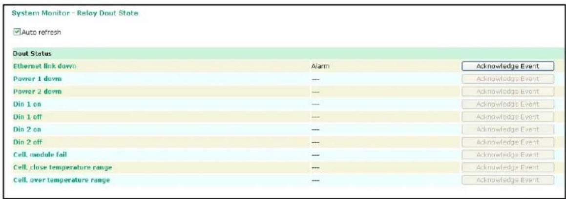
Dout State
Dout State refers to the relay output status, which can be configured to change upon the occurrence of certain system events through Auto Warning Settings under System Management. Click Dout State under
System Monitoring to display a list of events that may cause a change to the Dout state. If a configured alarm event occurs, the Dout state changes, and you can refer to this screen to determine the specific cause for the alarm. To reset the Dout state, click on Acknowledge Event.
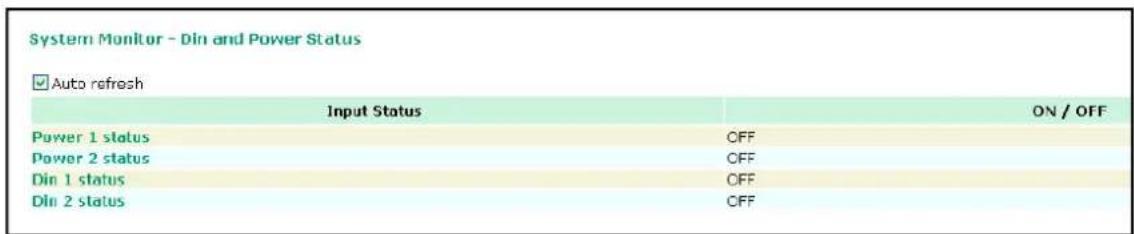
Din and Power Status
Go to Din and Power status under System Monitoring to display the power and digital input information.
Save Configuration
Go to Save Configuration and then click Save to save your submitted configuration changes to the OnCell 5000's flash memory. The configuration changes will be effective when the OnCell 5000 is restarted. If you do not save your changes before restarting, they will be discarded.
Save Configuration
If you have submitted any configuration changes, you must save the changes and restart the server before they take effect. Click Save to save the changes in the DnCall 5104's memory. To restart the server, go to Restart System in the navigation panel.
Sava
Restart
Restart System
Go to Restart System under Restart and then click Restart to restart the OnCell 5000. Ensure that you save all of your configuration changes before you restart the system or else these changes will be lost.
Restart System
III Warning III
Clicking Restart will disconnect all serial and Ethernet connections and reboot the OnCell 5104 server. NOTE: Unsaved configuration changes will be discarded, and data currently in the middle of transmission may be lost.
Restart
In this chapter, we explain how to configure a VPN with the OnCell 5000 web console.
The following topics are covered in this chapter:
□ What Are VPNs?
□ OnCell VPN Specifications
☐ OnCell VPN Web Console Settings
□ Manual Key/ ESP
Configuration
Remote Network
Local Network
- Incoming Security Settings
Outgoing Security Settings
□ ISAKMP/PSK
Configuration
Remote Network
➢ ISAKMP (Key Management)
Local Identity
➢ ISAKMP phase 1
➢ ISAKMP phase 2
▶ Advanced settings
☐ VPN system log events and error codes
What Are VPNs?
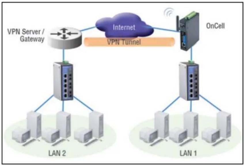
Computers that are part of a VPN use a second, "virtual" IP address to connect to the Internet. Instead of running across a single private network, some of the links between nodes that are part of a VPN use open network connections or virtual circuits on a larger network, such as the Internet. With the help of VPNs, cellular devices acting as a VPN client can initiate a connection with a VPN server. Once the connection is established, cellular devices can communicate with other network devices on the same private network.
flowchart
graph TD
    subgraph LAN 1
        A["Computer"] --> B["OnCell"]
        C["Computer"] --> D["OnCell"]
        E["Computer"] --> F["OnCell"]
        G["Computer"] --> H["OnCell"]
        I["Computer"] --> J["OnCell"]
        K["Internet"] --> L["OnCell"]
        M["VPN Server / Gateway"] --> N["Router"]
        O["VPN Tunnel"] --> P["Internet"]
    end
    style LAN 1 fill:#f9f,stroke:#333
    style LAN 2 fill:#ccf,stroke:#333
OnCell VPN Specifications
- OnCell IPSec provides security in one scenario with Gateway-to-gateway topology
- OnCell initiates VPN connection to VPN Server
- OnCell IPSec operates in Tunnel mode with IPsec VPN tunnel
➢ Manual Key/ESP, IKE/PSK
DES/3DES/AES128/AES192/AES256 encryption
MD5/SHA1 authentication
• IPsec NAT traversal, Anti-Replay, and PFS (Perfect Forwarding Secrecy).
Example: Gateway to Gateway Network Topology
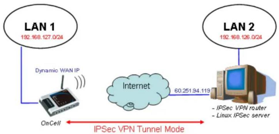
flowchart
graph LR
    A["LAN 1<br>192.168.127.0/24"] --> B["OnCell"]
    B --> C["Dynamic WAN IP"]
    C --> D["Internet"]
    D --> E["IPSec VPN router<br>- Linux IPSec server"]
    F["LAN 2<br>192.168.126.0/24"] --> G["IPSec VPN router<br>- Linux IPSec server"]
    style A fill:#f9f,stroke:#333
    style F fill:#f9f,stroke:#333
    style B fill:#ccf,stroke:#333
    style D fill:#cfc,stroke:#333
    style E fill:#fcc,stroke:#333
    linkStyle 0 stroke:#ff0000,stroke-width:2px
    linkStyle 1 stroke:#ff0000,stroke-width:2px
    linkStyle 2 stroke:#ff0000,stroke-width:2px
    linkStyle 3 stroke:#ff0000,stroke-width:2px
    linkStyle 4 stroke:#ff0000,stroke-width:2px
Figure: Gateway to gateway connection between OnCell and IPSec server
OnCell VPN Web Console Settings
From the left navigation panel, click Network Advanced Network Settings → VPN to configure the OnCell VPN Settings. The configuration items are shown below:
Manual Key/ ESP
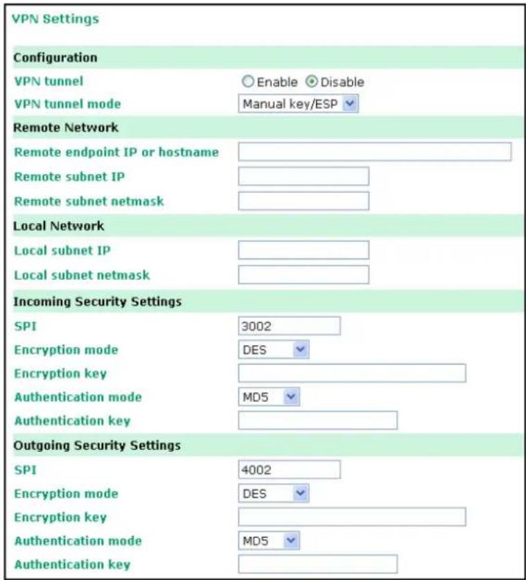
Configuration
VPN tunnel (default = Disable) : Enable or disable the VPN tunnel function.
VPN tunnel mode: The type of VPN tunnel policy to be used; either manual key IPsec or ISAKMP with Pre-shared Keys (PSK).
Remote Network
Remote endpoint IP or hostname: Enter the WAN IP or hostname of the remote VPN server endpoint.
Remote subnet IP: Enter the remote VPN server subnet IP of the remote network.
Remote subnet netmask: Enter the remote VPN server subnet netmask of the remote network.
Local Network
Local subnet IP: Enter the local OnCell LAN subnet IP.
Local subnet netmask: Enter the local OnCell LAN subnet netmask.
Incoming Security Settings
SPI: This sets the VPN manual key incoming SPI between 257 and 4294967295.
Encryption mode: Select the incoming encryption mode.
Encryption key: Enter the incoming encryption key.
| Encryption mode Length (Bytes) | |
| DES | 8 |
| 3DES | 24 |
| AES 128bit 16 | |
| AES 192bit 24 | |
| AES 256bit 32 |
Authentication mode: Select the incoming authentication mode.
Authentication key: Enter the incoming authentication key.
| Authentication mode Length (Bytes) | |
| MD5 | 16 |
| SHA1 | 20 |
Outgoing Security Settings
SPI: This sets the VPN manual key outgoing SPI between 257 and 4294967295.
Encryption mode: Select the outgoing encryption mode.
Encryption key: Enter the outgoing encryption key.
| Encryption mode Length (Bytes) | |
| DES | 8 |
| 3DES | 24 |
| AES 128bit 16 | |
| AES 192bit 24 | |
| AES 256bit 32 |
Authentication mode: Select the outgoing authentication mode.
Authentication key: Enter the outgoing authentication key.
| Authentication mode Length (Bytes) | |
| MD5 | 16 |
| SHA1 | 20 |
ISAKMP/PSK
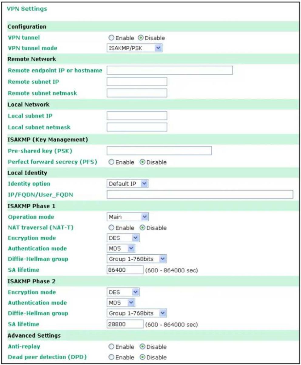
Configuration
VPN tunnel (default = Disable) : Enable or disable the VPN tunnel function.
VPN tunnel mode: The type of VPN tunnel policy to be used; either manual key IPsec or ISAKMP with Pre-shared Keys (PSK).
Remote Network
Remote endpoint IP or hostname: Enter the WAN IP or hostname of the remote VPN server endpoint.
Remote subnet IP: Enter the remote VPN server subnet IP of the remote network.
Remote subnet netmask: Enter the remote VPN server subnet netmask of the remote network.
ISAKMP (Key Management)
Pre-shared key (PSK): This sets the VPN ISAKMP Pre-Shared key settings.
Perfect forward secrecy (PFS) (default = Disable): Enable or disable the Perfect Forward Secrecy. PFS is an additional security protocol.
Local Identity
Identity option: Select additional ID authentication requirements for the VPN using a specific IP Address, FQDN, or User FQDN settings.
IP/ FQDN/ User_FQDN: Enter an ID (IP/FQDN/User_FQDN) to identify and authenticate the local VPN endpoint.
ISAKMP phase 1
Operation mode: Select main mode or aggressive mode to configure the standard negotiation parameters for IKE Phase 1 of the VPN Tunnel.
NAT-T (default = Disable): Enabling this option will allow IPSec traffic from this endpoint to traverse through the translation process during NAT. The remote VPN endpoint must also support this feature and it must be enabled to function properly over the VPN.
Encryption mode: Select the VPN ISAKMP phase 1 encryption mode.
Authentication mode: Select the VPN ISAKMP phase 1 authentication mode.
Diffie-Hellman group: Select the VPN ISAKMP phase 1 DH group. As the DH Group number increases, the higher the level of encryption implemented for PFS
SA life time (default = 86400): Enter the number of seconds for the VPN ISAKMP phase 1 Lifetime. This is the period of time to pass before establishing a new IPSec security association (SA) with the remote endpoint.
ISAKMP phase 2
Encryption mode: Select the VPN ISAKMP phase 2 encryption mode.
Authentication mode: Select the VPN ISAKMP phase 2 authentication mode.
Diffie-Hellman group: Select the VPN ISAKMP phase 2 DH group. As the DH Group number increases, the higher the level of encryption implemented for PFS
SA life time (default = 28800): Enter the number of seconds for the VPN ISAKMP phase 2 Lifetime. This is the period of time to pass before establishing a new IPSec security association (SA) with the remote endpoint.
Advanced settings
Anti-replay (default = Disable): Anti-replay is the method of not allowing an intercepted packet message to be sent to the recipient multiple times without the original sender knowing.
Dead Peer Detection (DPD) (default = Disable): Enable or disable the Dead Peer Detection. DPD is a method of detecting a dead Internet Key Exchange (IKE) peer. It sends a DPD packet to the peer every 60 seconds under no traffic and attempt to connect normally. If the DPD packet fails 5 times the VPN will continuously re-establish a connection.
VPN system log events and error codes
| VPN system log Description | |
| VPN init. VPN tunnel initial | |
| VPN init. by packet VPN tunnel initial by packet | driven |
| VPN stop VPN tunnel stop | |
| VPN phase2 SA time out VPN tunnel phase 2 | security association time out |
| VPN time out VPN tunnel connect time out | |
| VPN has mismatched proposal VPN tunnel proposal not match | |
| VPN disconnected by change WAN IP VPN tunnel | disconnected by change WAN IP |
| VPN disconnected by DPD VPN disconnected by | Dead peer detection |
| VPN start phase1 main mode connect VPN tunnel | start phase 1 main mode connect |
| VPN start phase1 aggr. mode connect | VPN tunnel start phase1 aggressive mode connect |
| VPN start encryption | VPN tunnel start encryption |
| VPN phase1 pass | VPN tunnel phase 1 pass |
| VPN phase2 pass | VPN tunnel phase 2 pass |
| VPN Error Code 0001 ~ 0030 | VPN tunnel others error codeNote: For details refer to "Notify Messages - Error Types" on page 40in http://docbox.etsi.org/ Reference/IETF/RFC/RFC2408.pdf |
| VPN phase2 renew key | VPN tunnel phase 2 renew key |
| VPN phase2 renew key success | VPN tunnel phase 2 renew key success |
| VPN phase1 SA time out VPN tunnel phase 1 | security association time out |
| VPN phase1 key(ISAKMP) deleted by remote | VPN tunnel phase 1 key(ISAKMP) deleted by remote |
| VPN phase2 key(ESP) deleted by remote | VPN tunnel phase 2 key(ESP) deleted by remote |
Configuring OnCell Central Management Software
In this chapter, we introduce OnCell Central Management Software, and explain how to configure OnCell Central Management Software with the OnCell 5000 web console, install and set the OnCell Central Driver Manager, and cover all of the equipment specifications.
The following topics are covered in this chapter:
☐ Step 1: Server Settings
System Requirements
Installing OnCell Central Manager
➢ Using OnCell Central Manager
☐ Step 2: OnCell Device Web Console Settings
OnCell Central Settings
OnCell Central Server
Service Forwarding
☐ Step 3: Host Settings and Management
OnCell Central Web Console
□ Server
Overview
▶ Control Ports/User Ports Information.
Account Settings
Device
All Devices
All User Ports
Service Forwarding
➢ Firmware Upgrade
Device's Settings and Ma intenance
Overview
User Ports
Service Forwarding
Maintenance
□ Logout
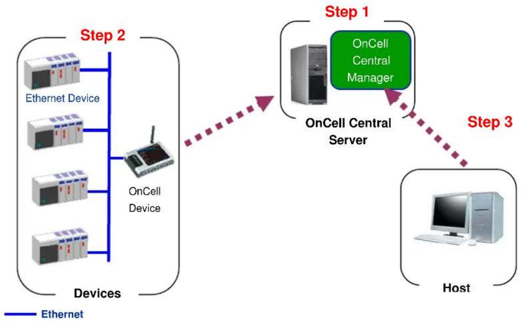
flowchart
graph TD
    A["Ethernet Device"] --> B["OnCell Device"]
    C["Ethernet Device"] --> B
    D["Ethernet Device"] --> B
    E["Ethernet Device"] --> B
    B --> F["OnCell Central Server"]
    F --> G["OnCell Central Manager"]
    G --> H["Step 1"]
    H --> I["OnCell Central Server"]
    I --> J["Step 3"]
    J --> K["Host"]
    style A fill:#f9f,stroke:#333
    style C fill:#f9f,stroke:#333
    style D fill:#f9f,stroke:#333
    style E fill:#f9f,stroke:#333
    style F fill:#ccf,stroke:#333
    style G fill:#cfc,stroke:#333
    style H fill:#fcc,stroke:#333
    style I fill:#cff,stroke:#333
    style J fill:#ffc,stroke:#333
    style K fill:#fcc,stroke:#333
Step 1: Server Settings
System Requirements
Hardware Requirements
Your computer's hardware must meets the following minimum requirements:
- Pentium III or above
• 500 MHz CPU (1 GHz recommended)
• 256 Mb RAM (1 GB recommended)
• 300 MB disk space
Software Requirements
OnCell Central Manager runs on the following operating systems:
• Microsoft Windows 2000 Server
• Microsoft Windows Server 2003
• Microsoft Windows Server 2008
- Internet Explorer 6.0 above is required.
Installation Requirements
Installing OnCell Central Manager software involves two main elements:
- Adobe Flash
- OnCell Central Manager software
Installing OnCell Central Manager
To install the OnCell Central Manager software, follow these steps. This procedure requires that you have administrative privileges. Insert the OnCell Installation CD into the OnCell Central Server.
-
Click the INSTALL OnCell Central Manager button in the OnCell Installation CD auto-run window to install the OnCell Central Manager. Once the installation program starts running, click Yes to proceed.
-
Click Next when the Welcome screen opens to proceed with the installation.
- Click Next to install program files to the default directory, or click Browse to select an alternate location.

- Click Next to install the program's shortcuts in the appropriate Start Menu folder.
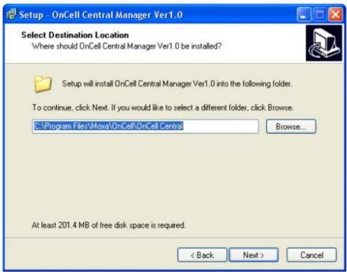
- Click Next to proceed with the installation. You will be prompted to select additional tasks.
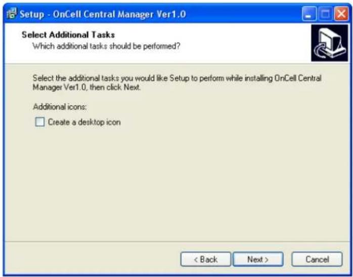
- Click Next to proceed with installation. Setup will display a summary of the installation options.

- Click Install to begin installation. The setup window will report the installation progress. To change the installation settings, click Back and navigate to the previous screen.
- Click Finish to complete the installation of the OnCell Central Manager.
Using OnCell Central Manager
After you install OnCell Central Manager, you can set up the OnCell 5000's OnCell Central Settings for your PC host. Make sure the settings on your OnCell 5000 match the settings for OnCell Central Manager.
- Go to Start → OnCell Central → OnCell Central to start the OnCell Central mapping software.
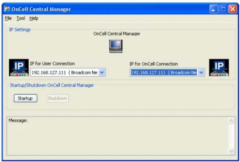
You may need to install Adobe Flash before using this OnCell Central Server. The system will give you the link for installation automatically. Alternatively, you may find the Adobe Flash in the CD as well.
- Click on Tool → Control Ports Settings to modify the port number.
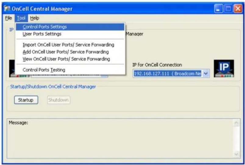
To modify the new configuration of control ports, you can make all configuration changes here. The Control Ports Setting's information must match the web console's OnCell Central Server Settings. Please refer to Step 2, OnCell Device Web Console Settings, for control port information. Click Save if any modifications have been made.
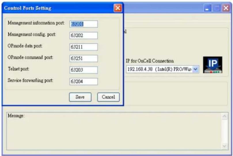
- Click on Tool → User Ports Settings to modify the port number. Click Save if any modifications have been made.
User Ports are used to connect the host and OnCell Central Server. The User Ports are assigned by the OnCell Central Server to each OnCell device sequentially within the specified port range.
Data port: Ports used to communicate with serial devices connected to the OnCell.
Command port: The TCP port for listening to SSDK commands from the host.
Service forwarding: Ports used to communicate with Ethernet devices connected to the OnCell.
Telnet port: The telnet port is the TCP listening port that allows the host to configure the OnCell via Telnet.
NOTE: Enabling Remove registered ports will remove the already assigned port numbers within the specified port range from the system.
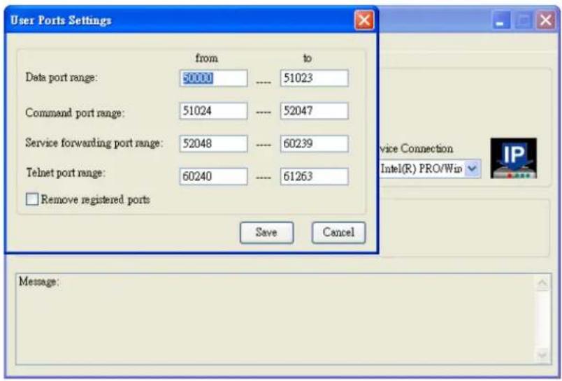
- If you need to import/add a long pre-defined device list to the OnCell Central Server, follow the next step, otherwise skip directly to Step 9.
- To import the configuration from a text file, click on Tool → Import OnCell User Ports/ Service Forwarding.
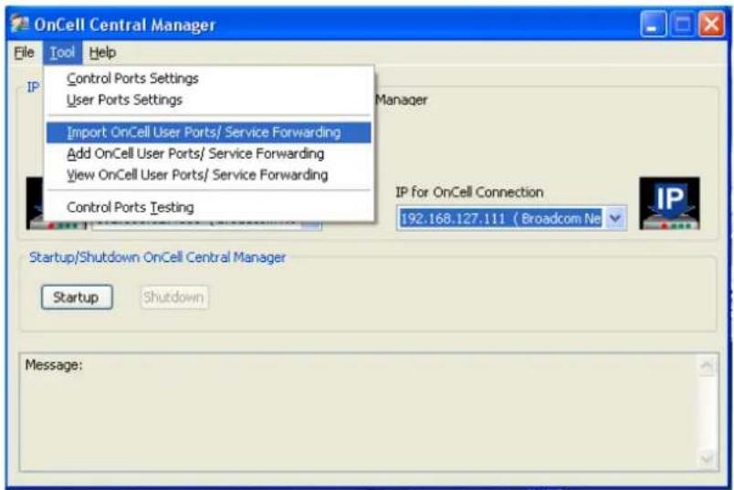
Browse to locate the configuration file (file format can be .txt for the following import format) and then click Import (same step as Import Service Forwarding).
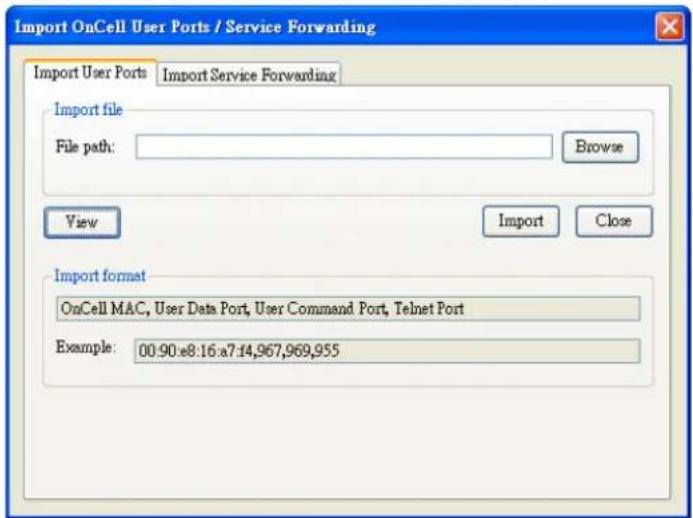
- Alternatively, for OnCell User Ports and Service Forwarding, you can manually enter the information. Click on Tool → Add OnCell User Ports/ Service Forwarding.
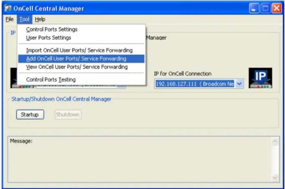
(Same step as Import Service Forwarding.)
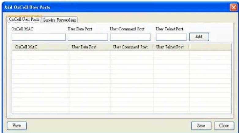
- In order to view the information you have been imported or added, click on View (same step as Import Service Forwarding).
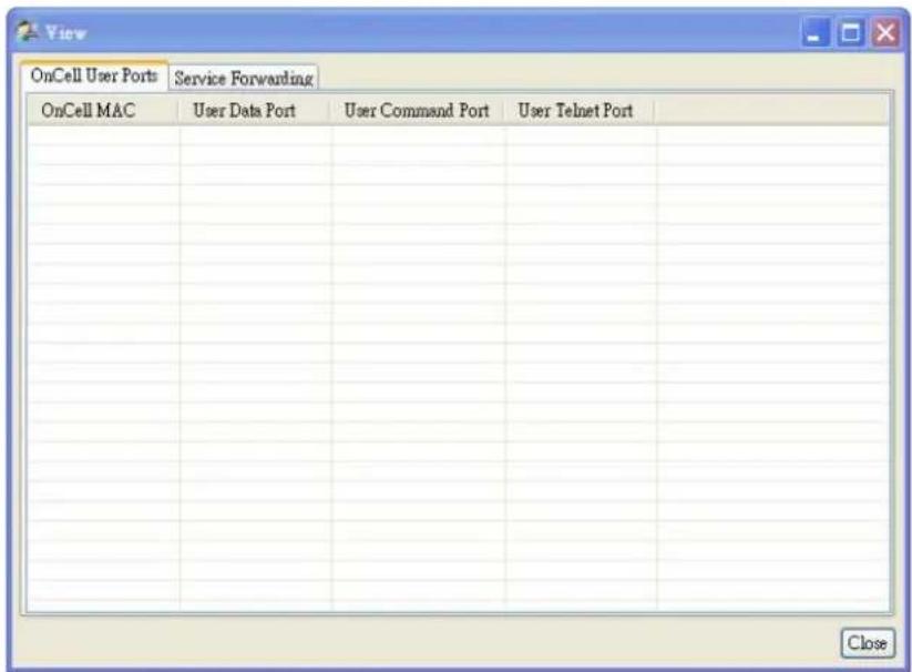
- To save All the configuration settings to an xml file format, select Export DataBase from the OnCell Central menu. You will then be able to import this configuration file to another host and use the same OnCell Central settings on the other host.
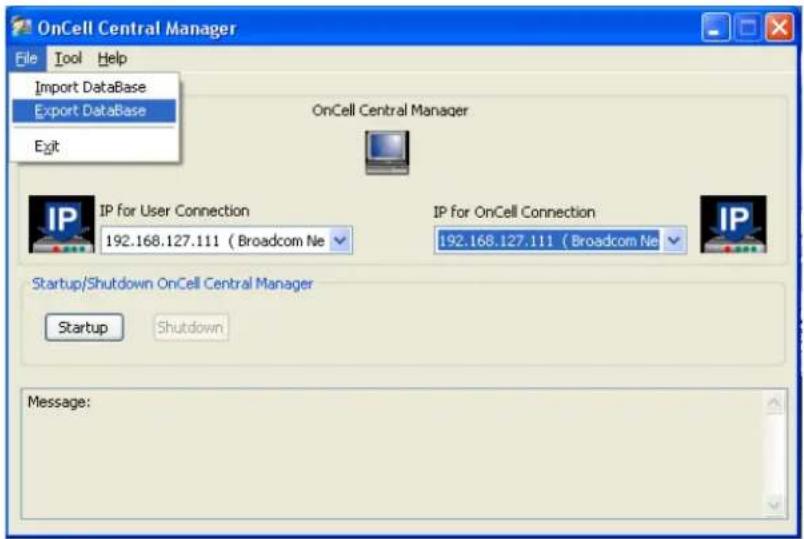
- When all the configurations have been completed, return to the OnCell central main page. If your OnCell Central Server has two LAN cards, you may need to select the IP that needs to pass through the OnCell Connection and User Connection, and then click Startup.
For security reasons, we use 2 LAN cards for the server, one for the private IP domain in User Connection, and another for the public IP domain in OnCell Connection (OnCell Central must be accessible from the public IP domain).
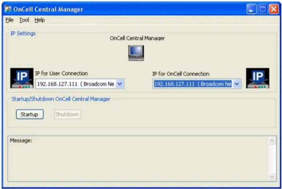
Step 2: OnCell Device Web Console Settings
OnCell Central Settings
From the left navigation panel, click Network Settings → OnCell Central Settings → OnCell Central Server to configure the OnCell Central Settings. The configuration items are shown below:
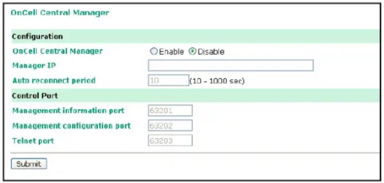
OnCell Central Server
Configuration
Server (default=Disable): If you select Enable, the OnCell will be ready to connect to the OnCell Central Server
Server IP: Enter the IP address that will be assigned to your OnCell Central Server. The IP address must be in the Public IP domain.
Auto reconnect period (default=10 s): This field specifies the idle time setting for auto-reconnect.
Control Port
Management information port (default=63201): This port is used to transfer status information of the OnCell to the OnCell Central Server. The port number must match the OnCell Central Manager's port number configured in the OnCell Central Server. In order to prevent port conflicts with other applications, you can set the management information port to another port if needed.
Management configuration port (default=63202): This port is used to transfer configurations from the OnCell to the OnCell Central Server. The port number must match the OnCell Central Manager's port number configured in the OnCell Central Server. In order to prevent a port conflict with other applications, you can set the management information port to another port if needed.
Telnet port (default=63203): The Telnet port is the TCP port that is listening for Telnet connection from the host side. In order to prevent a TCP port conflict with other applications, you can set the Telnet port to another port if needed.
Service Forwarding
From the left navigation panel, click Network Settings → OnCell Central Settings → Service Forwarding to configure the OnCell Central Settings. The configuration items are shown below:
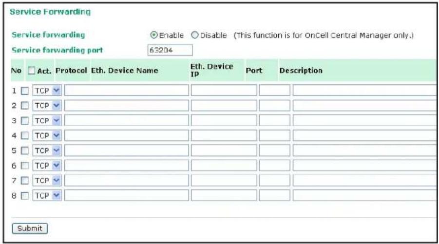
Service forwarding (default=Disable): If enabled, this option will establish the Ethernet device connection of the OnCell device to OnCell Central Server. Up to 8 Ethernet devices can be stored in the Service Forwarding Table.
Service forwarding port: Ports used to establish the Ethernet port connection of the OnCell device to OnCell Central Server.
Step 3: Host Settings and Management
Before you connect to OnCell Central's Web, you must install Adobe Flash, which you can download from Adobe Flash Web Site: http://get.adobe.com/flashplayer/
If you are using Microsoft Windows 2000 Server, Microsoft Windows 2008 Server, or Microsoft Windows Server 2003 platform, you may need to enable your ActiveX control on your platform. For other platform versions, refer directly to the Host Settings.
- Start Internet Explorer and click on Tool → Internet Options.
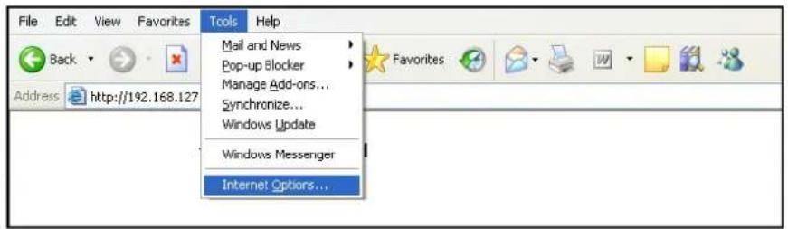
- Select Security Settings, select Internet, and then click Custom Level.
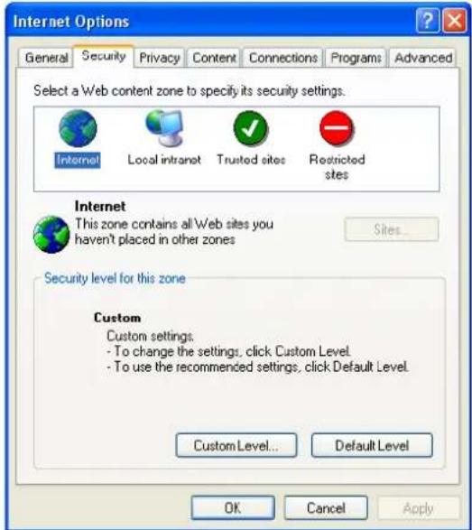
- Enable Download signed ActiveX controls.
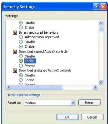
- Enable Run ActiveX controls and plug-ins.
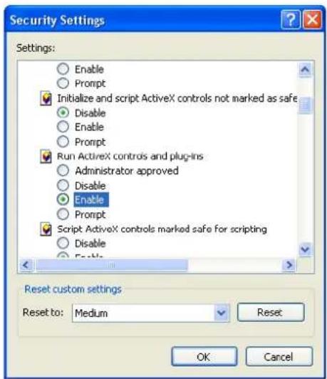
- Enable Script ActiveX controls marked safe for scripting and then click OK.
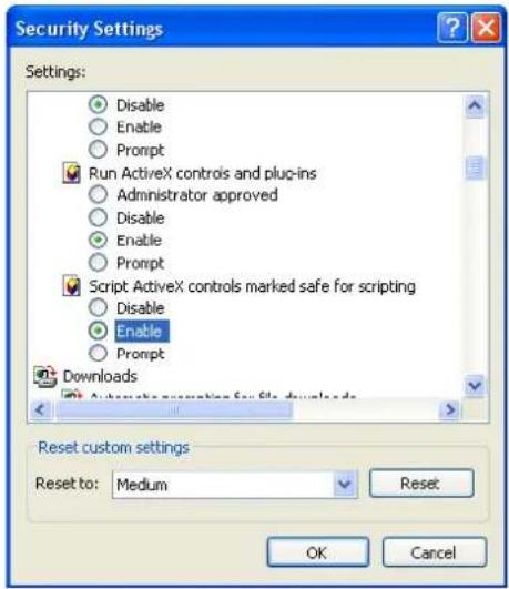
- Select Trusted sites under Security and then click on Sites...
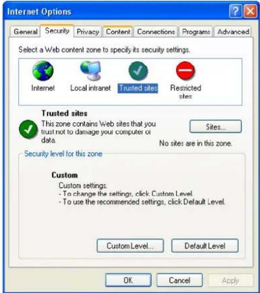
- Enter your IP address for your OnCell Central's web page, then click Add.
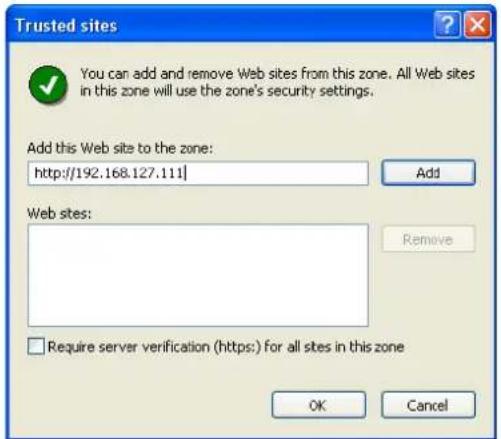
8. Click on Custom Level...
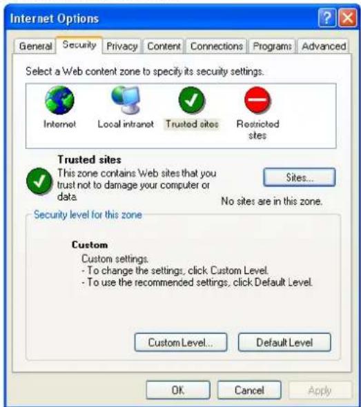
9. Enable Download signed ActiveX controls
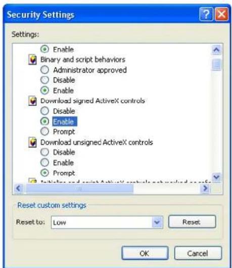
10. Enable Run ActiveX controls and plug-ins
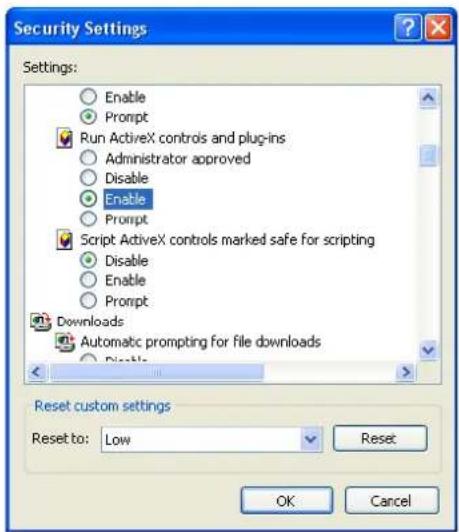
- Enable Script ActiveX controls marked safe for scripting and then click OK
OnCell Central Web Console
- Start the web browser.
- In the Address input box, enter the OnCell Central's web IP address follow with the 8080 port (e.g., 192.168.127.111:8080). You should see the OnCell Central Manager Welcome page.
- Enter the default username and password and then click Login.
Username: admin
Password: admin
- The OnCell Central page will open:

From this page, you can change the view to one of the following options:
- Server
- Device
- Logout
Server
This section describes how to change the connection ports number for device and host in order to establish a connection with OnCell Central Server. If you would like to change your account settings, you can use the instructions in this section to do so.
Overview
The page shows which OnCell Central Manager version number you are using.
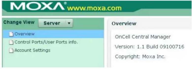
Control Ports/ User Ports Information.

Control Ports Information.
Control ports are used to establish a connection between an OnCell device and the OnCell Central Server. This section shows all control port information that has already been configured.
User Ports info.
User ports are used to establish a connection between the host and the OnCell Central Server. This section shows all ranges of user ports that have been configured. See page 6-25 for an explanation of each user port.
Account Settings
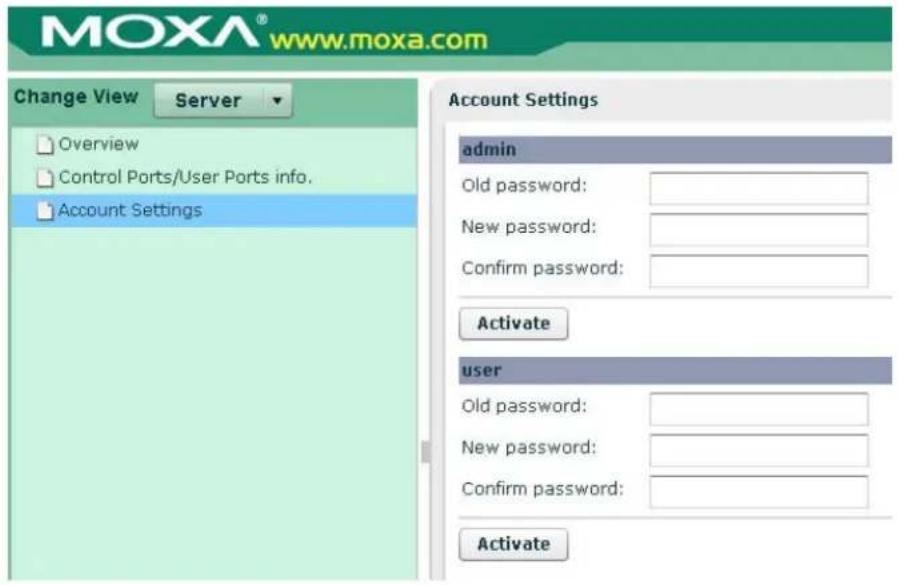
For all changes to the OnCell Central's admin and password protection settings, you will first need to enter the old password. To set up a new password or change the existing password, enter your desired password under both New password and Confirm password.
Device
This section describes ways in which you can monitor all of the device information that appears in the Device List.
If this is the first time that you have used OnCell Central, be aware that the list of groups in the left pane and the Device List will be empty, since you have not added any devices yet.
If you are managing hundreds of devices, the Device List can be very long, and searching the list to locate a particular device can be inconvenient and time-consuming. However, you can use the All Devices, All User Ports, and Service Forwarding tab to view a smaller amount of information, which makes monitoring much easier.
All Devices
This table describes All Devices that are connected to OnCell Central Server:
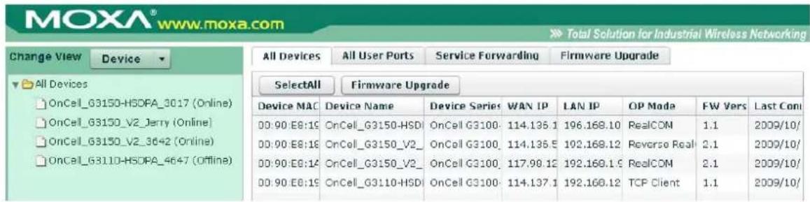
| Item Description | |
| Device MAC Each Device has unique | MAC ID that you can find on the device label or web/telnet/serial console |
| Device Name Device's Name | |
| WAN IP Device's WAN IP address | |
| LAN IP Device's LAN IP address | |
| OP mode Device's operation mode (does not apply to the OnCell 5004 and 5104) | |
| FW Version Device's firmware version | |
| Last Connected Device's last connection date, month, time | |
Refresh: The device list is refreshed when this button is pressed. New online devices will be shown at the top of the list.
Auto Refresh (30 secs): If you checkmark this box, the new online device list will be updated every 30 seconds.
Group Edit. When you create groups of devices, you can efficiently apply device settings or perform maintenance tasks on multiple devices at the same time. To create a group, click the right mouse button and select Group Edit.

After creating the group, you can copy the devices under All Devices folder to create a new folder (e.g., South A).
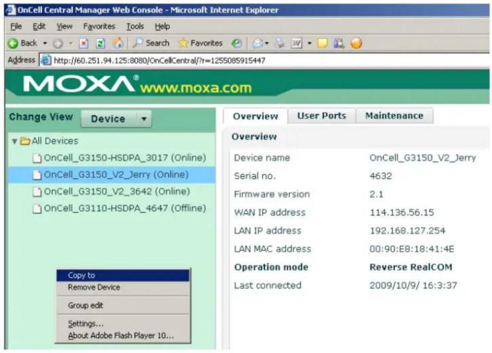
Remove Device. To maintain the list, you can remove all offline devices. To activate this function, click the right mouse button and select Remove Device.
Note: If a device is removed from the All Devices Folder then the same device will be removed from all other new folders, too.
All User Ports
The All User Ports table displays the host's established connections to the OnCell Central Server, and its corresponding OnCell devices.
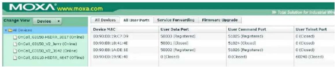
| Item Description | |
| Device MAC Each Device has a unique | MAC ID that you can find on the device label or web/telnet/serial console. |
| User Data Port The port number allows the host to establish a serial data connection to OnCell Central, which is mapped to the OnCell device (does not apply to the OnCell 5004 and 5104). | |
| User Command Port | The port number allows the host to establish a command connection to OnCell Central, which is mapped to the OnCell device (does not apply to the OnCell 5004 and 5104). |
| User Telnet Port The port number allows the host to establish a telnet connection to OnCell Central, which is mapped to the OnCell device. | |
Service Forwarding
The Service Forwarding table displays the host's established Ethernet connection to the OnCell Central Server, and the corresponding OnCell devices.
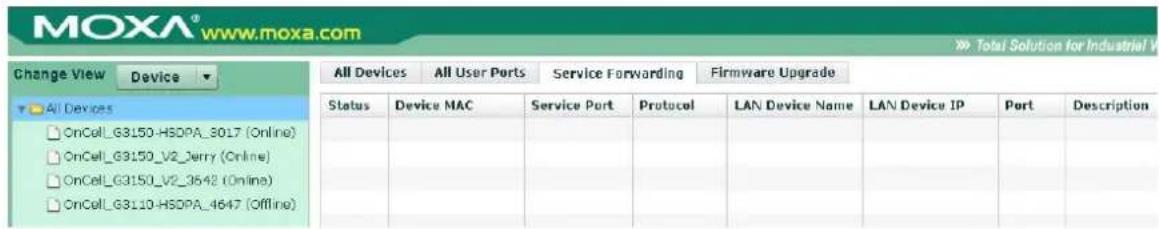
| Item Description | |
| Status Shows the status | of the user's service ports.Closed: this mean the port is not connectedRegistered: this mean the OnCell is connected to OnCell Central Server-connected: this mean the host side is connected to OnCell Central Server and is ready to use. |
| Device MAC Each Device | has a unique MAC ID that you can find on the device label or web/telnet/serial console. |
| Service Port | The port number allows the host to establish an Ethernet connection to the OnCell Central, which is mapped to the OnCell device. |
| Protocol Protocol type for | Service forwarding connection |
| LAN Device Name Device's Name | |
| LAN Device IP Device's IP address | |
| Port This is the Ethernet | device's local port number. |
| Description Detailed description of the device. | |
Firmware Upgrade
The Firmware Upgrade table displays the firmware upgrade status of your devices.
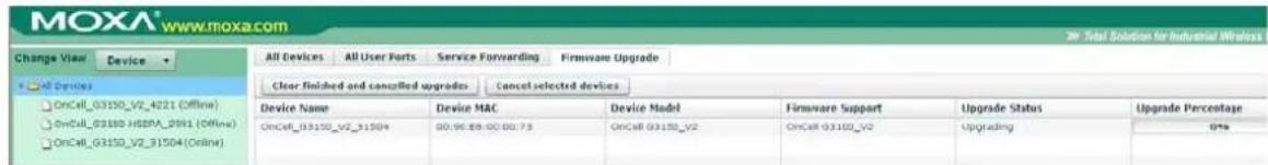
| Item Description | |
| Device Name Device's name | |
| Device MAC Each device's unique MAC ID, which can be found on the device label | |
| Device Model | Device's model |
| Firmware Support | Device's firmware version |
| Upgrade Status | Shows the status of the firmware upgrade:Success: this mean the firmware upgrade was successfulFail: this mean the firmware upgrade has failedCancel: this mean the firmware upgrade was canceled |
| Upgrade Percentage | Displays the percentage of firmware that has been uploaded. |
If you are the administrator, you have ability to use Clear finished and cancelled upgrades and Cancel selected devices icons on Firmware Upgrade page, and Select All and Firmware Upgrade on the All devices page.
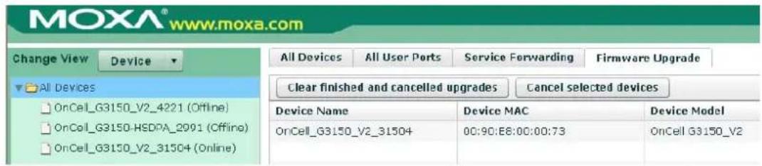
Clear finished and cancelled upgrades: This button clears all firmware upgrades that have been finished and canceled.
Cancel selected devices: This button cancels the firmware upgrading process of the selected device(s).
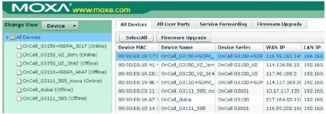
Select All: This button makes it easy to select all of your devices for firmware upgrades.
Firmware Upgrade: This button will initiate a firmware upgrade for the devices you have selected.
Device's Settings and Maintenance
From the left navigation panel, click the All Device folder to list all devices, and then select the device that you want to monitor or reconfigure.
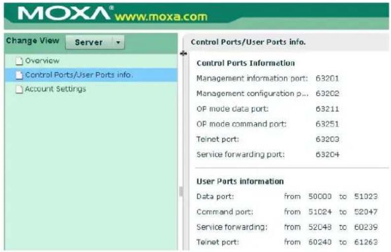
Overview
This page shows the OnCell's device information:
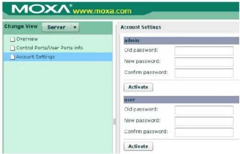
User Ports
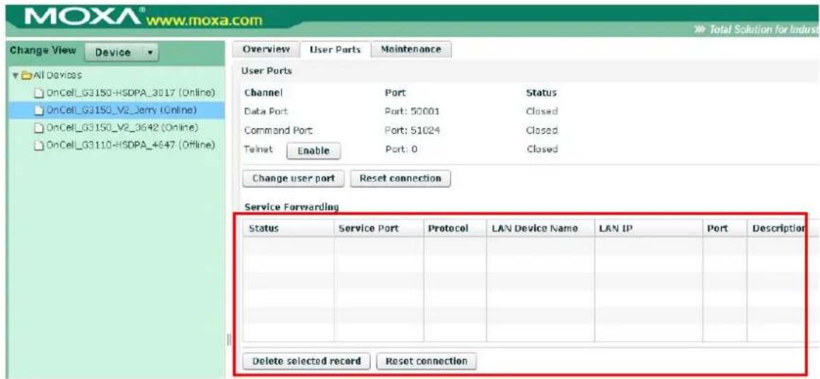
Telnet Enable: If you click on the enable icon, Telnet will permit the the host to connect to the OnCell device. If no connections are made within 30sec, the port will just close.
Change User Port: If you do not want to use the system's assigned user ports, you may change the User Data Port, User Command Port, and Telnet Port here (does not apply to the OnCell 5004 and 5104).
Reset connection: Use this option to disconnect existing connections.
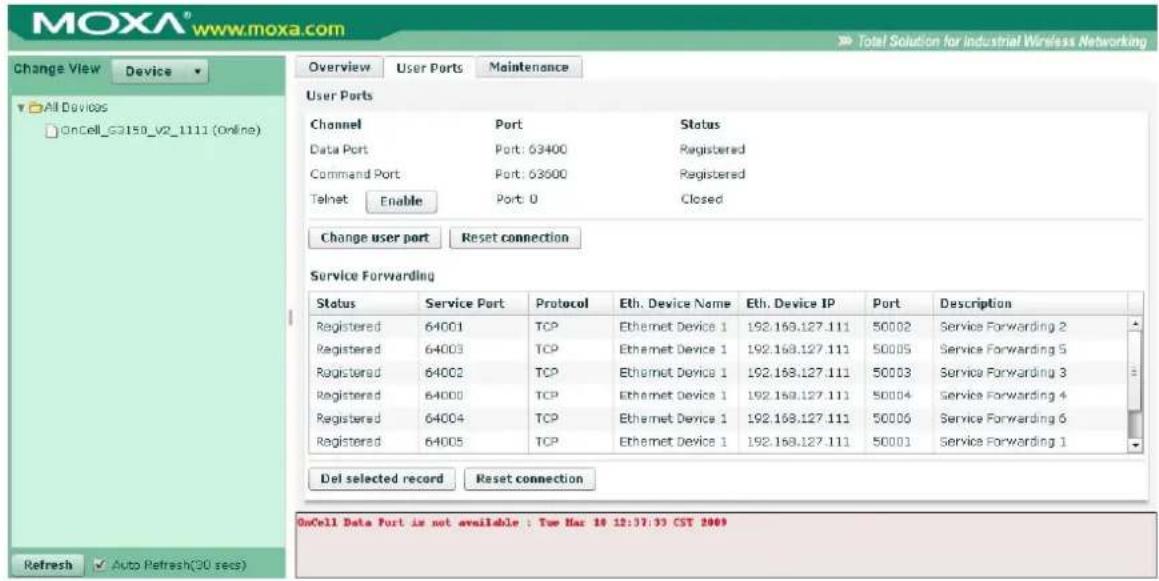
Note: If the data or command port is occupied, an error message will appear at the bottom of the window.
Service Forwarding
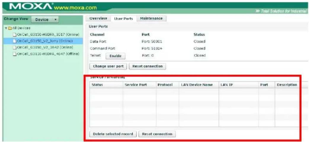
| Item Description | |
| Status Show the status of the User Service Port.Closed: Means the port is not connected.Registered: Mean the OnCell is connected to OnCell Central Server-connected: Means the host side is connected to OnCell Central Server, and is ready to use. | |
| Service Port | The port number allows the host to establish an Ethernet connection to OnCell Central, which maps to the OnCell device. |
| Protocol Protocol type for Service forwarding connection | |
| LAN Device Name Device's Name | |
| LAN Device IP Device's IP address | |
| Port This is the Ethernet device's local port number. | |
| Description Detailed description of the device | |
Del selected record: Allows you to delete the device information under service forwarding that you have highlighted.
Reset connection: This is used to disconnect existing connections.
Maintenance
Configuration Export
To save all tconfigurations to an xml file, select Configuration Export and then click Download.
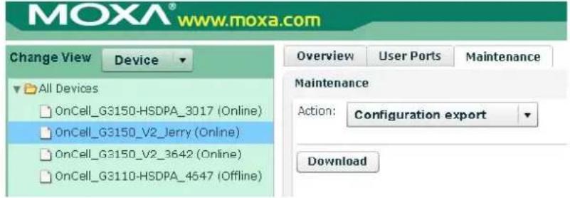
Configuration Import
Allows you to import this configuration file to another host and use the same OnCell Central settings in the other host.
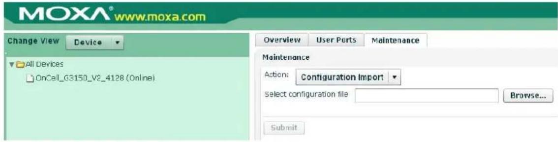
Restart OnCell Device
Click Restart to restart the OnCell 5000 device. Be sure that you save all of your configuration changes before you restart the system, or the changes will be lost.
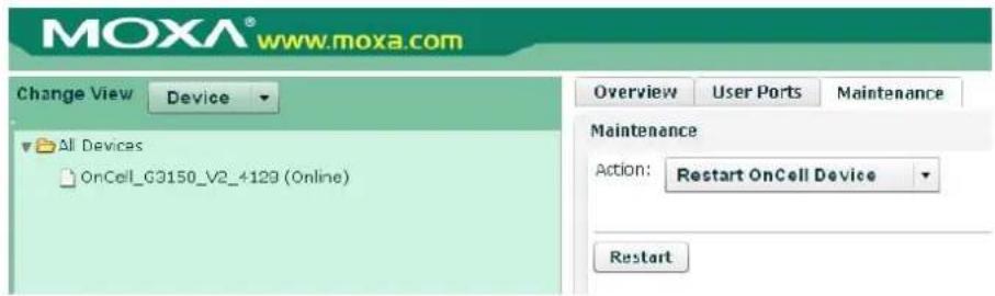
Logout
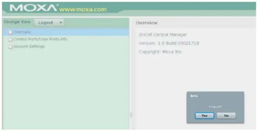
The following topics are covered in this chapter:
□ Installing the Search Utility
□ Configuring the OnCell Search Utility
Installing the Search Utility
- Click the INSTALL UTILITY button in the OnCell Installation CD auto-run window to install OnCell Search Utility. Once the program starts running, click Yes to proceed.
- Click Next when the Welcome screen opens to proceed with the installation.
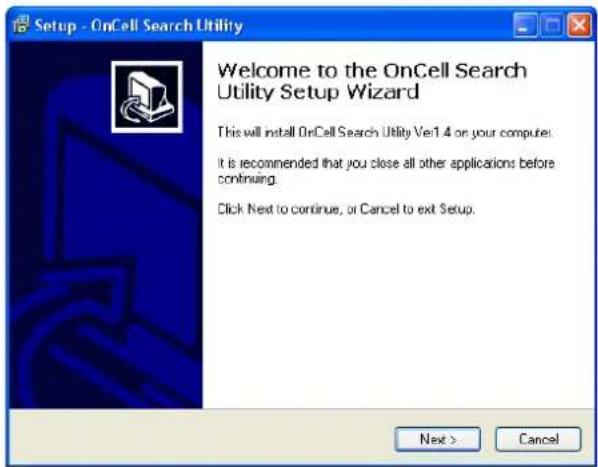
- Click Next to install program files to the default directory, or click Browse to select an alternate location.
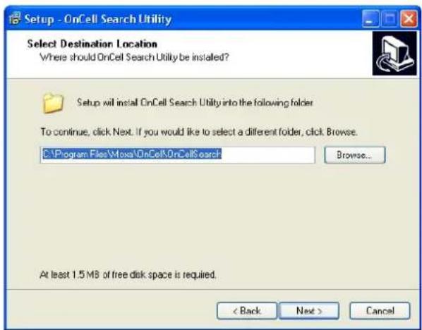
- Click Next to select additional tasks.
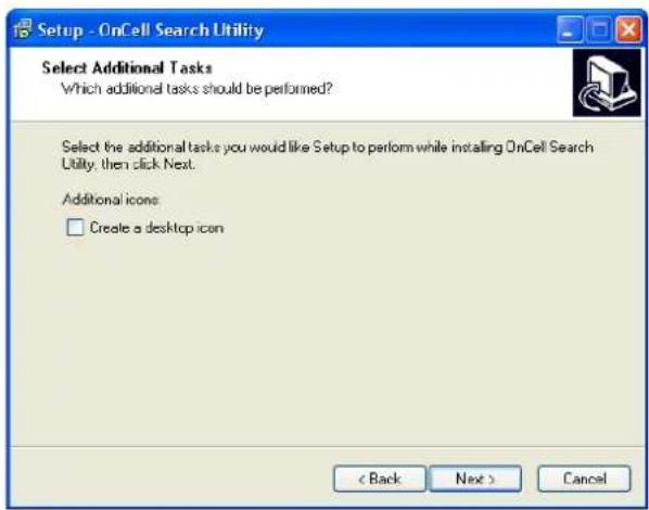
- Click Next to proceed with the installation. The installer then displays a summary of the installation options.
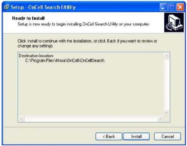
- Click Install to begin the installation. The setup window will report the progress of the installation. To change the installation settings, click Back and navigate to the previous screen.
- Click Finish to complete the installation of OnCell Search Utility.
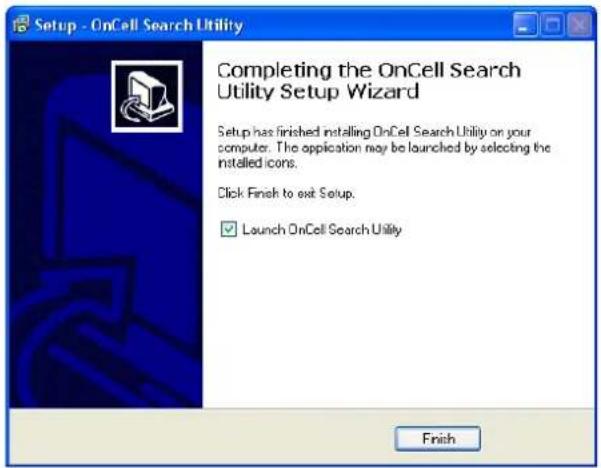
Configuring the OnCell Search Utility
The Broadcast Search function is used to locate all OnCell 5000 servers that are connected to the same LAN as your computer. After locating an OnCell 5000, you will be able to change its IP address.
Since the Broadcast Search function searches by MAC address and not IP address, all OnCell 5000 servers connected to the LAN will be located, regardless of whether or not they are part of the same subnet as the host.
- Open OnCell Search Utility and then click the Search icon.
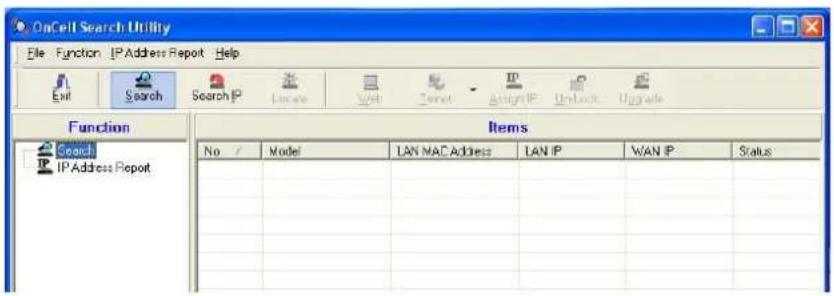
The Searching window indicates the progress of the search.
- When the search is complete, all OnCell 5000 servers that were located will be displayed in the OnCell Search Utility window.
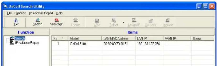
- Click Locate to cause the selected device to beep.
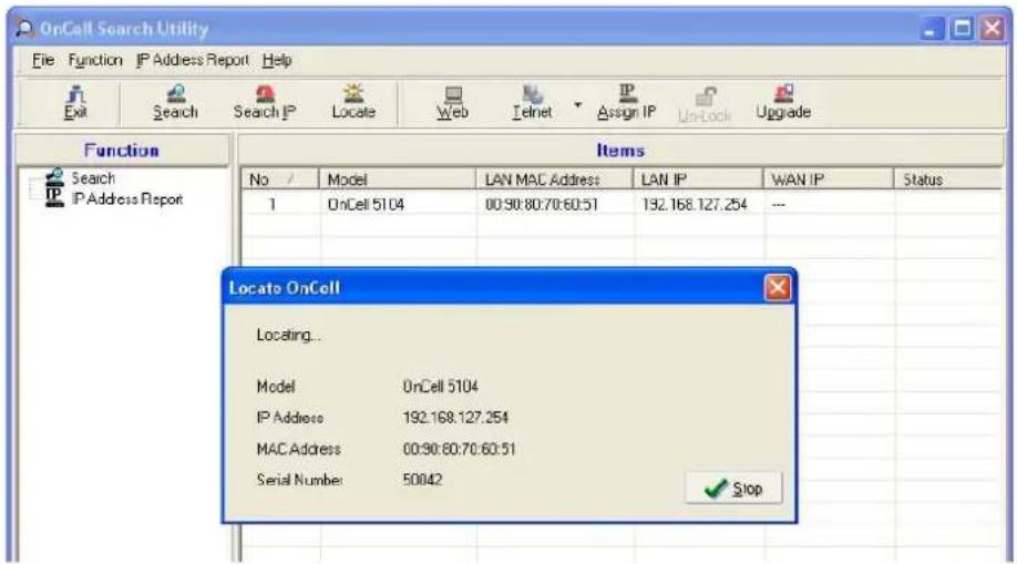
- To modify the configuration of the highlighted OnCell 5000, click on the Console icon to open the web console. This will take you to the web console, where you can make all configuration changes. Please refer to Chapter 4, Using the Web Console, for information on how to use the web console.
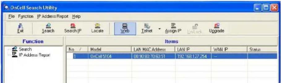
- Select IP Address Report for monitoring the status of the IP Address, and then click Go.
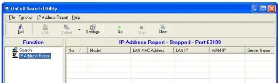
- To change the configuration of the IP Address Report, click on the Settings icon to open the IP Location Settings. The Local UDP listen Port number should match the web console Auto IP Report Settings' port number.

- Click the Go icon to complete the configuration. Refer to Chapter 4, Using the Web Console, for information on how to use the IP Address Report.
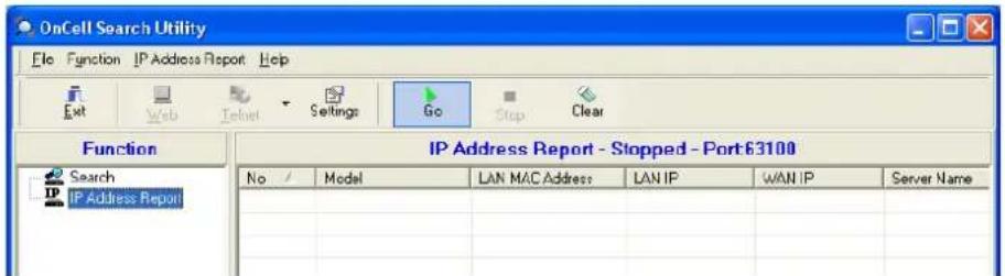
| Setting Name Default Name | |
| Web Console Login | |
| Username | admin |
| Password | Keep |
| Network Settings | |
| LAN IP address 192.168.127.254 | |
| WAN IP address 192.168.126.254 | |
| Network | 255.255.255.0 |
| WAN Preference Cellular | |
| Cellular Settings | |
| SIM PIN | |
| NAT service Enable | |
| DHCP Service Settings | |
| DHCP Server Enable | |
| DNS relay Enable | |
| Virtual Server Settings | |
| Virtual Server Disable | |
| Route Table | |
| Static Route | Disable |
| WAN IP Filter Configuration | |
| WAN IP Filter | Disable |
This appendix explains how to use the OnCell 5000 with DDNS. When the OnCell 5000 receive its IP address from a DHCP (Dynamic Host Configuration Protocol) server, remote servers will be unable to access it using a fixed IP address. With DDNS (Dynamic Domain Name Server), a remote server can access the OnCell G3100 using its domain name instead of its IP address.
Overview
The following is a summary of the process:
- The OnCell 5000 sends a request for an IP address to the DHCP server. At the same time, it notifies the DHCP server of its desired server name ("OC3100" in the illustration) according to the option 12 standard.
-
The DHCP server replies with the IP address that is assigned to the OnCell 5000, along with the domain name ("moxa.com" in the illustration) and the IP addresses for the DNS server and gateway.
-
If the OnCell 5000 has authorization to update the DNS server, it will register its FQDN (Fully Qualified Domain Name) with the DNS server. The OnCell 5000's FQDN will be in the format server name.domain name ("OC3100.moxa.com" in the illustration).
-
If the OnCell 5000 is not authorized to update the DNS server, the DHCP server can be used to update the DNS server. The DHCP server will register the DNS server with the PTR RR (the record of request for a domain name with IP address).
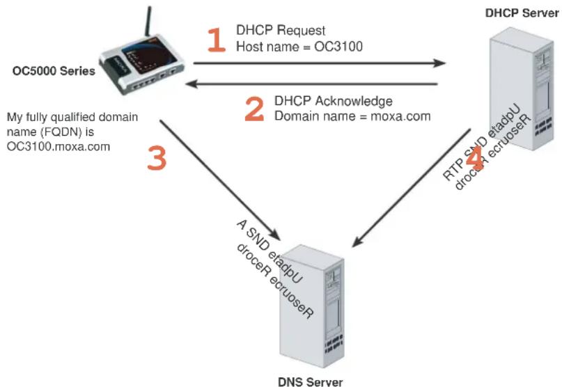
flowchart
graph TD
    A["OC5000 Series"] -->|1 DHCP Request Host name = OC3100| B["DHCP Server"]
    B -->|2 DHCP Acknowledge Domain name = moxa.com| A
    A -->|3 My fully qualified domain name (FQDN) is OC3100.moxa.com| C["DNS Server"]
    C -->|4 RTP SND etadpU droceR ecruoserR| B
    C -->|A SND etadpU droceR ecruoserR| A
![DHCP Scope [192.160.20.0] DN.moxa.com.tw Properties Action View Tree DHCP root-5g4g6nd Scope [192 Address Address Reserv Scope Server Opt General DNS Advanced You can set up the DHCP server to automatically update name and address information on DNS servers that support dynamic updates. ✓ Automatically update DHCP client information in DNS ● Update DNS only if DHCP client requests ○ Always update DNS □ Discard forward (name-to-address) lookups when lease expires ✓ Enable updates for DNS clients that do not support dynamic update Specifies whether the DHCP server sends dynamic updates to the DNS server for any DHCP clients that do not directly support performing these updates. If selected, clients running under order versions of Windows are updated by the DHCP server for both their host (A) and pointer (I PTR) resource records. By default, Windows 2000 DHCP clients are enabled to send dynamic updates to their configured DNS servers for their host (AI) resource records, but typically do not update pointer (I PTR) resource records unless configured to do so. Configured in TCP/IP properties for a server. OK Cancel Apply](/content/2026/05/1143689/images/57026130506d2f2040d98eea59e273efb044ec9ccddc7392df571913c19a1046.jpg)
The above screenshot shows how DHCP can be set up to update the DNS.
Currently, the OnCell 5000 supports DNS service as provided by DynDNS. For detailed information on this option, please visit https://www.dyndns.com.
Configuration
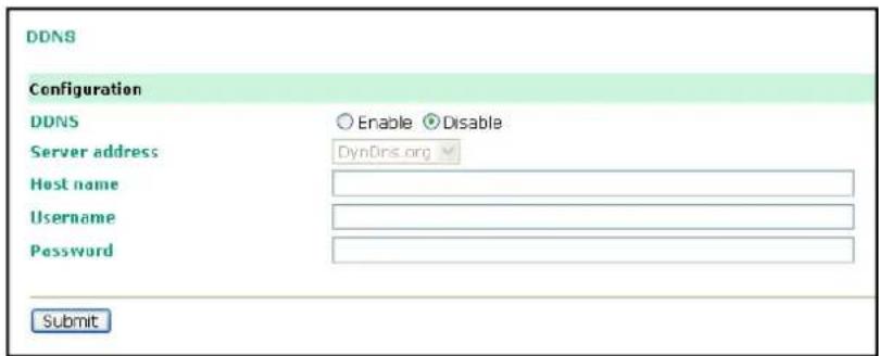
DDNS (default=Disable): Use this field to enable or disable DDNS.
Server address (default=DynDns.org): Currently, DynDns.org is the only option available for Server address.
Host name: In this field, use the name that you created on www.dyndns.com. The OnCell 5000 will update the DynDNS server with this host name.
Username: This is the user name used for update authentication.
Password: This is the password used for update authentication.
OnCell Series provides several ways to configure the Ethernet IP addresses. One of them is DHCP Client. When you set up the OnCell to use DHCP Client to configure Ethernet IP addresses, it will automatically send a DHCP request over the Ethernet to find the DHCP Server. And then the DHCP Server will send an available IP address to the OnCell. The OnCell will use this IP address for a period of time after receiving it. But the OnCell will send a DHCP request again to the DHCP Server. Once the DHCP Server realizes that this IP address is to be released to other DHCP Client, the OnCell then will receive a different IP address. For this reason, users sometimes find that the OnCell will use different IP addresses, not a fixed IP address.
In order to know what IP address the OnCell is using, you need to set up parameters in Network Settings via Web browser. The figure below is the OnCell Web console configuration window. Enter the IP address and the Port number of the PC that you want to send this information to.

Auto IP Report Format
| "Moxa", 4 bytes Info[0] | Info[1] ... Info[n] |
Info [n]
| Field | ID | Length | Data |
| Length 1 1 Variable, Length is “Length Field” | |||
ID List
| ID Value Description Length Note | |||
| 1 | Server Name | Variable ASCII char | |
| 2 | Hardware ID | 2 | Little-endian |
| 3 | MAC Address | 6 | 6 bytes MAC address. If the MAC address is "00-90-E8-01-02-03", the MAC[0] is 0, MAC[1] is 0x90(hex), MAC[2] is 0xE8(hex), and so on. |
| 4 | Serial Number | 4, DWORD | Little-endian |
| 5 | IP Address | 4, DWORD | Little-endian (LAN IP) |
| 9 | AP ID | 4, DWORD | Little-endian |
| 10 | IP Address2 | 4, DWORD | Little-endian (WAN IP) |
| 11 | Signal Level | 1 | Unsigned char |
| 12 | RSSI | 1 | Unsigned char |