TK-RP08 - Repeater TRENDNET - Free user manual and instructions
Find the device manual for free TK-RP08 TRENDNET in PDF.

User questions about TK-RP08 TRENDNET
0 question about this device. Answer the ones you know or ask your own.
Ask a new question about this device
Download the instructions for your Repeater in PDF format for free! Find your manual TK-RP08 - TRENDNET and take your electronic device back in hand. On this page are published all the documents necessary for the use of your device. TK-RP08 by TRENDNET.
USER MANUAL TK-RP08 TRENDNET
- Before You Start 1
- How to Install 2
- Operation and Configuration 5
Troubleshooting 7
1. Before You Start
natural_image
Exterior view of a black electronic device labeled 'Sina.com' with ports and indicator lights (no readable text beyond branding)Package Contents
- TK-RP08
- Quick Installation Guide
• Utility CD-ROM - RS-232 Cable
• RJ-45 Ethernet Cables - Rack Mount Brackets
- Power Cord
System Requirements
- RJ-45 Ethernet Cables
- AC-powered Device
• Windows 98SE/2000/XP/Vista PC required - TK-IP101 (Optional)
- Broadband/DSL Router (e.g. TW100-S4W1CA)(Optional)
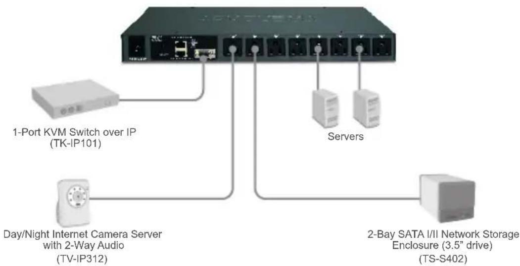
Application
Remote Power Controller (TK-RP08)
flowchart
graph TD
    A["3.5" Network"] --> B["Day/Night Internet Camera Server with 2-Way Audio (TV-IP312)"]
    A --> C["1-Port KVM Switch over IP (TK-IP101)"]
    A --> D["2-Bay SATA I/II Network Storage Enclosure (3.5" drive) (TS-S402)"]
    A --> E["Servers"]
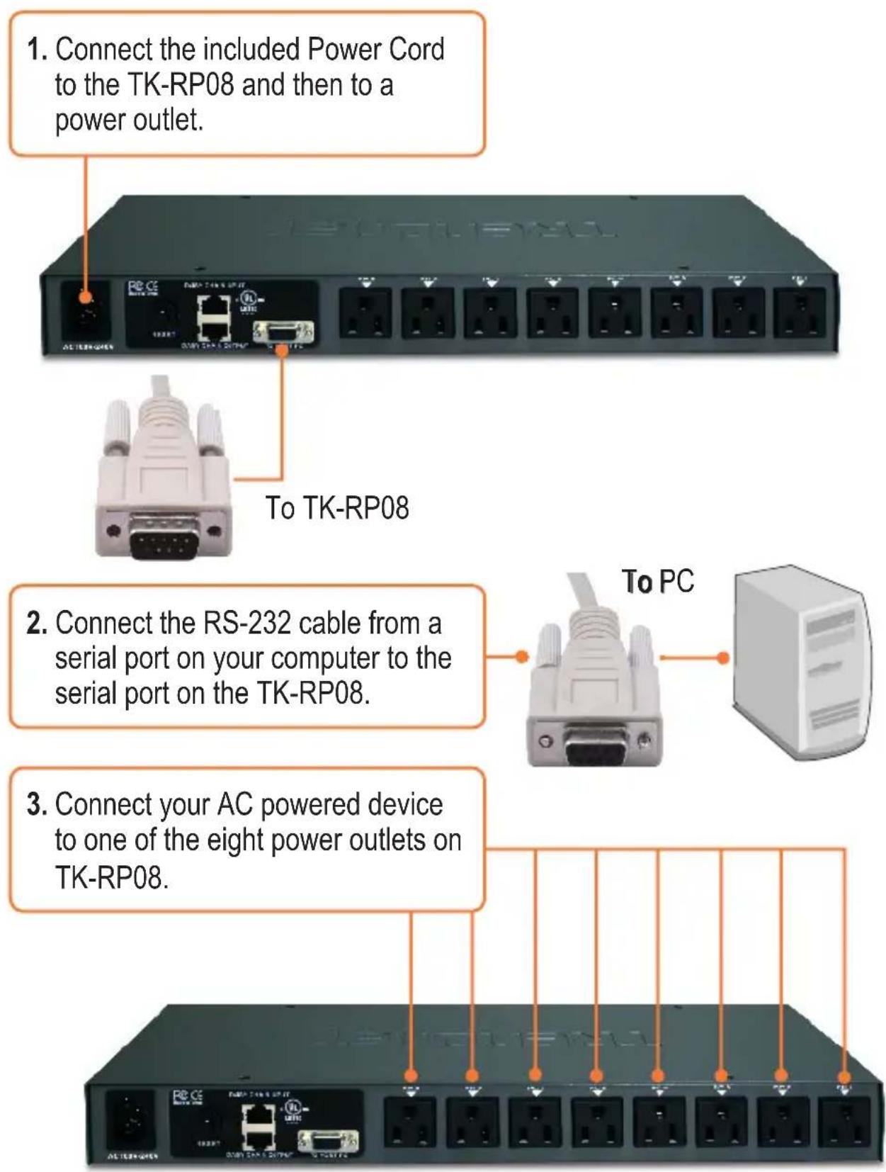
2. How to Install
Standalone
Daisy Chain
Note: You can daisy chain up to 16 TK-RP08 together, with a maximum of 128 AC powered devices.
- Connect one end of the provided RJ-45 Ethernet cable to the Daisy Chain Output port on the first TK-RP08 (master).
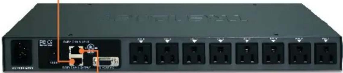
natural_image
Front view of a network switch device with ports and connectors (no readable text or symbols)-
Connect the opposite end of the RJ-45 Ethernet cable to the Daisy Chain Input port on the second TK-RP08 (slave).
-
If you have a third TK-RP08, connect one end of the provided RJ-45 Ethernet cable to the Daisy Chain Output port on the second KVM switch. Then connect the opposite end of the RJ-45 Ethernet cable to the Daisy Chain Input port on the third (slave) TK-RP08. Repeat for each additional TK-RP08.
Rack Mount
The KVM Switch can be mounted in an EIA standard-size, 19-inch rack, which can be placed in a wiring closet with other equipment.
Note: If you would like to mount the KVM switch to a EIA 19" equipment rack, install the included mounting brackets to the sides of the KVM switch, secure them with the screws provided, and then mount the KVM switch to the equipment rack with the hardware provided by the equipment rack manufacturer.
- Attach the mounting brackets to both sides of the KVM switch and secure them with the provided screws.
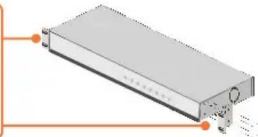
natural_image
3D diagram of a rectangular electronic component with internal structure and mounting holes (no text or symbols)- Carefully position the KVM switch onto the rack. Align the bracket to the screw holes on the rack, then use the screws provided with the equipment rack to mount the KVM switch.
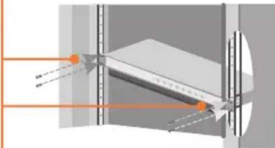
natural_image
Diagram of an optical system with light paths and focal points, no text or symbols presentYour installation is now complete.
Register Your Product
To ensure the highest level of customer service and support, please take a moment to register your product Online at: www.TRENDnet.com/register Thank you for choosing TRENDnet
3. Operation and Configuration
LEDs and Push Buttons
Current
Indicates the amount of current being used. The maximum allowable current is 15 amps. When exceeded, this LED will flash.
Push Buttons
Press the push buttons to power on and off the power outlet. Press on it for 2 seconds.
Bank Number
Indicates the sequence of the KVM switch when daisy-chained.
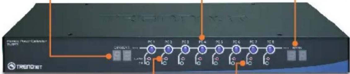
ALARM
When this LED is solid red, the power outlet is not working properly. When this LED is off, the power outlet is working fine. When this LED is flashing red, timer scheduled is enabled for that port or firmware is being upgraded.
ON
When this LED is green, the power outlet is powered on. When this LED is off, the power outlet is powered off.
Local Access and Management (Windows Users)
- Insert the Utility CD-ROM into your CD-ROM drive. Then click Install Utility.

- Follow the InstallShield Wizard instructions and then click Finish.
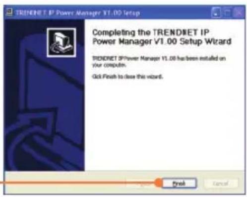
- Double click the TRENDnet IP Power Manager icon on your desktop.

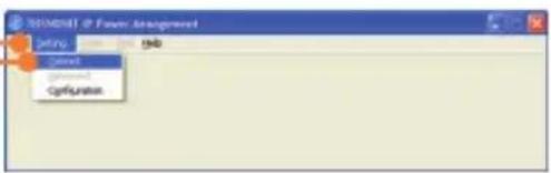
- Click on Setting, and then click Connect.
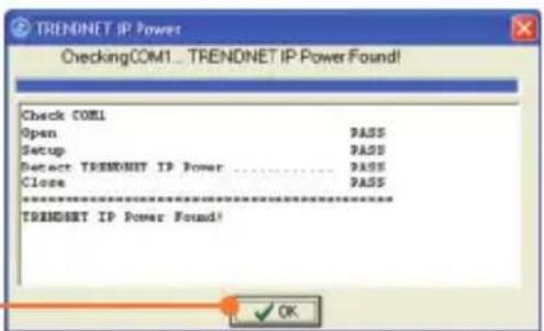
- Click OK.
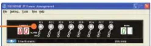
- Click the power button.
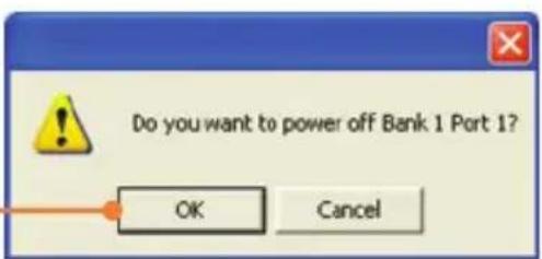
- Click OK.
Troubleshooting
Q1: My AC-powered device does not power on after I press on the power button for the power outlet on the TK-RP08. What should I do?
A1: First, make sure the provided power cord is plugged into the TK-RP08 and into the power outlet. Second, make sure the AC powered device is properly plugged into one of the power outlets on the TK-RP08. Third, make sure to press the power button for at least two seconds before releasing. Fourth, press the reset button on the TK-RP08.
Q2: I double click on the IP Power Manager icon, but I am unable to make a connection. What should I do?
A2: First, make sure the computer is connected to the serial port on the TS-RP08. Second, connect the RS-232 cable to a different serial port on the computer. Third, connect to a different computer.
Q3: The Alarm LED is red. What should I do?
A3: First, turn off and disconnect the device attached to the corresponding power outlet. Press the power button to the corresponding power outlet several times. Second, press on the reset button on the back.
Q4: The Current LED is flashing. What should I do?
A4: The maximum allowable current load – 15 amps – has been exceeded. Try shutting down some devices to keep the current below 15 amps.
Q5: Can I use HyperTerminal to configure the TK-RP08?
A5: Yes you can. The port settings must be configured as shown below:
Bits Per Second: 9600
Data bits: 8
Parity: None
Stop bits: 1
Flow Control: Hardware
Please refer to the User Guide on the Utility CD-ROM for list of commands. Make sure to exit out of the IP Power Management Utility first.
If you still encounter problems or have any questions regarding the TK-RP08, please contact Trendnet's Technical Support Department.
Certifications
This equipment has been tested and found to comply with FCC and CE Rules.
Operation is subject to the following two conditions:
(1) This device may not cause harmful interference.
(2) This device must accept any interference received. Including interference that may cause undesired operation.


Waste electrical and electronic products must not be disposed of with household waste. Please recycle where facilities exist. Check with you Local Authority or Retailer for recycling advice.

NOTE: THE MANUFACTURER IS NOT RESPONSIBLE FOR ANY RADIO OR TV INTERFERENCE CAUSED BY UNAUTHORIZED MODIFICATIONS TO THIS EQUIPMENT. SUCH MODIFICATIONS COULD VOID THE USER'S AUTHORITY TO OPERATE THE EQUIPMENT.
ADVERTENCIA
TRENDnet Technical Support
US · Canada
Toll Free Telephone: 1(866) 845-3673
24/7 Tech Support

Europe (Germany • France Italy Spain Switzerland UK)
Toll Free Telephone: +00800 60 76 76 67
English/Espanol - 24/7
Worldwide
Telephone: +(31) (0) 20 504 05 35
English/Espanol - 24/7
Product Warranty Registration
Please take a moment to register your product online.
Go to TRENDnet's website at http://www.trendnet.com/register
TRENDNET®
20675 Manhattan Place
Torrance, CA 90501
USA